EP1880787A1 - Process for repairing turbine engine components - Google Patents
Process for repairing turbine engine components Download PDFInfo
- Publication number
- EP1880787A1 EP1880787A1 EP07252471A EP07252471A EP1880787A1 EP 1880787 A1 EP1880787 A1 EP 1880787A1 EP 07252471 A EP07252471 A EP 07252471A EP 07252471 A EP07252471 A EP 07252471A EP 1880787 A1 EP1880787 A1 EP 1880787A1
- Authority
- EP
- European Patent Office
- Prior art keywords
- metal material
- refractory metal
- process according
- repair
- piece
- Prior art date
- Legal status (The legal status is an assumption and is not a legal conclusion. Google has not performed a legal analysis and makes no representation as to the accuracy of the status listed.)
- Ceased
Links
- 238000000034 method Methods 0.000 title claims abstract description 53
- 230000008569 process Effects 0.000 title claims abstract description 49
- 239000000463 material Substances 0.000 claims abstract description 108
- 239000003870 refractory metal Substances 0.000 claims abstract description 85
- 230000008439 repair process Effects 0.000 claims abstract description 64
- 239000000945 filler Substances 0.000 claims abstract description 48
- 238000003466 welding Methods 0.000 claims abstract description 31
- 238000010438 heat treatment Methods 0.000 claims abstract description 15
- 238000005266 casting Methods 0.000 claims abstract description 8
- 238000000151 deposition Methods 0.000 claims abstract description 8
- 229910052751 metal Inorganic materials 0.000 claims abstract description 8
- 239000002184 metal Substances 0.000 claims abstract description 8
- 239000007769 metal material Substances 0.000 claims description 36
- PXHVJJICTQNCMI-UHFFFAOYSA-N Nickel Chemical compound [Ni] PXHVJJICTQNCMI-UHFFFAOYSA-N 0.000 claims description 24
- 238000002844 melting Methods 0.000 claims description 16
- 230000008018 melting Effects 0.000 claims description 16
- 239000011888 foil Substances 0.000 claims description 12
- 229910052759 nickel Inorganic materials 0.000 claims description 12
- 239000011248 coating agent Substances 0.000 claims description 10
- 238000000576 coating method Methods 0.000 claims description 10
- ZOKXTWBITQBERF-UHFFFAOYSA-N Molybdenum Chemical compound [Mo] ZOKXTWBITQBERF-UHFFFAOYSA-N 0.000 claims description 8
- 229910052750 molybdenum Inorganic materials 0.000 claims description 8
- 239000011733 molybdenum Substances 0.000 claims description 8
- 229910045601 alloy Inorganic materials 0.000 claims description 7
- 239000000956 alloy Substances 0.000 claims description 7
- 238000005520 cutting process Methods 0.000 claims description 6
- WFKWXMTUELFFGS-UHFFFAOYSA-N tungsten Chemical compound [W] WFKWXMTUELFFGS-UHFFFAOYSA-N 0.000 claims description 6
- 239000010937 tungsten Substances 0.000 claims description 6
- 229910052721 tungsten Inorganic materials 0.000 claims description 6
- 239000010410 layer Substances 0.000 claims description 5
- VYZAMTAEIAYCRO-UHFFFAOYSA-N Chromium Chemical compound [Cr] VYZAMTAEIAYCRO-UHFFFAOYSA-N 0.000 claims description 4
- PNEYBMLMFCGWSK-UHFFFAOYSA-N aluminium oxide Inorganic materials [O-2].[O-2].[O-2].[Al+3].[Al+3] PNEYBMLMFCGWSK-UHFFFAOYSA-N 0.000 claims description 4
- 229910052804 chromium Inorganic materials 0.000 claims description 4
- 239000011651 chromium Substances 0.000 claims description 4
- KZHJGOXRZJKJNY-UHFFFAOYSA-N dioxosilane;oxo(oxoalumanyloxy)alumane Chemical compound O=[Si]=O.O=[Si]=O.O=[Al]O[Al]=O.O=[Al]O[Al]=O.O=[Al]O[Al]=O KZHJGOXRZJKJNY-UHFFFAOYSA-N 0.000 claims description 4
- 239000011261 inert gas Substances 0.000 claims description 4
- 229910052863 mullite Inorganic materials 0.000 claims description 4
- 229910052758 niobium Inorganic materials 0.000 claims description 4
- 239000010955 niobium Substances 0.000 claims description 4
- GUCVJGMIXFAOAE-UHFFFAOYSA-N niobium atom Chemical compound [Nb] GUCVJGMIXFAOAE-UHFFFAOYSA-N 0.000 claims description 4
- 230000001590 oxidative effect Effects 0.000 claims description 4
- 238000010926 purge Methods 0.000 claims description 4
- 229910000601 superalloy Inorganic materials 0.000 claims description 4
- 229910052715 tantalum Inorganic materials 0.000 claims description 4
- GUVRBAGPIYLISA-UHFFFAOYSA-N tantalum atom Chemical compound [Ta] GUVRBAGPIYLISA-UHFFFAOYSA-N 0.000 claims description 4
- 239000002253 acid Substances 0.000 claims description 3
- 238000005524 ceramic coating Methods 0.000 claims description 3
- 239000011247 coating layer Substances 0.000 claims description 3
- 239000011224 oxide ceramic Substances 0.000 claims description 3
- 229910052574 oxide ceramic Inorganic materials 0.000 claims description 3
- 229910021332 silicide Inorganic materials 0.000 claims description 3
- FVBUAEGBCNSCDD-UHFFFAOYSA-N silicide(4-) Chemical compound [Si-4] FVBUAEGBCNSCDD-UHFFFAOYSA-N 0.000 claims description 3
- 239000000126 substance Substances 0.000 claims description 3
- 230000004888 barrier function Effects 0.000 claims description 2
- 238000009792 diffusion process Methods 0.000 claims description 2
- 230000000694 effects Effects 0.000 claims description 2
- 238000007747 plating Methods 0.000 claims 3
- 238000005275 alloying Methods 0.000 description 6
- 239000011324 bead Substances 0.000 description 6
- 239000007789 gas Substances 0.000 description 4
- 239000000203 mixture Substances 0.000 description 3
- QAOWNCQODCNURD-UHFFFAOYSA-N Sulfuric acid Chemical compound OS(O)(=O)=O QAOWNCQODCNURD-UHFFFAOYSA-N 0.000 description 2
- 230000008021 deposition Effects 0.000 description 2
- -1 e.g. Substances 0.000 description 2
- 238000003754 machining Methods 0.000 description 2
- BASFCYQUMIYNBI-UHFFFAOYSA-N platinum Chemical compound [Pt] BASFCYQUMIYNBI-UHFFFAOYSA-N 0.000 description 2
- 239000000843 powder Substances 0.000 description 2
- XLYOFNOQVPJJNP-UHFFFAOYSA-N water Substances O XLYOFNOQVPJJNP-UHFFFAOYSA-N 0.000 description 2
- 229910000531 Co alloy Inorganic materials 0.000 description 1
- GRYLNZFGIOXLOG-UHFFFAOYSA-N Nitric acid Chemical compound O[N+]([O-])=O GRYLNZFGIOXLOG-UHFFFAOYSA-N 0.000 description 1
- NPXOKRUENSOPAO-UHFFFAOYSA-N Raney nickel Chemical compound [Al].[Ni] NPXOKRUENSOPAO-UHFFFAOYSA-N 0.000 description 1
- 239000000919 ceramic Substances 0.000 description 1
- 229910017052 cobalt Inorganic materials 0.000 description 1
- 239000010941 cobalt Substances 0.000 description 1
- GUTLYIVDDKVIGB-UHFFFAOYSA-N cobalt atom Chemical compound [Co] GUTLYIVDDKVIGB-UHFFFAOYSA-N 0.000 description 1
- 238000004891 communication Methods 0.000 description 1
- 238000001816 cooling Methods 0.000 description 1
- 238000004090 dissolution Methods 0.000 description 1
- 230000006698 induction Effects 0.000 description 1
- 238000005495 investment casting Methods 0.000 description 1
- NPURPEXKKDAKIH-UHFFFAOYSA-N iodoimino(oxo)methane Chemical compound IN=C=O NPURPEXKKDAKIH-UHFFFAOYSA-N 0.000 description 1
- 229910052741 iridium Inorganic materials 0.000 description 1
- GKOZUEZYRPOHIO-UHFFFAOYSA-N iridium atom Chemical compound [Ir] GKOZUEZYRPOHIO-UHFFFAOYSA-N 0.000 description 1
- 238000003698 laser cutting Methods 0.000 description 1
- 239000000155 melt Substances 0.000 description 1
- 150000002739 metals Chemical class 0.000 description 1
- 238000001000 micrograph Methods 0.000 description 1
- 238000012986 modification Methods 0.000 description 1
- 230000004048 modification Effects 0.000 description 1
- 229910000907 nickel aluminide Inorganic materials 0.000 description 1
- 229910017604 nitric acid Inorganic materials 0.000 description 1
- ZODDGFAZWTZOSI-UHFFFAOYSA-N nitric acid;sulfuric acid Chemical compound O[N+]([O-])=O.OS(O)(=O)=O ZODDGFAZWTZOSI-UHFFFAOYSA-N 0.000 description 1
- 230000003647 oxidation Effects 0.000 description 1
- 238000007254 oxidation reaction Methods 0.000 description 1
- 238000001259 photo etching Methods 0.000 description 1
- 229910052697 platinum Inorganic materials 0.000 description 1
- 230000002265 prevention Effects 0.000 description 1
- 239000010453 quartz Substances 0.000 description 1
- 239000011819 refractory material Substances 0.000 description 1
- 230000003252 repetitive effect Effects 0.000 description 1
- VYPSYNLAJGMNEJ-UHFFFAOYSA-N silicon dioxide Inorganic materials O=[Si]=O VYPSYNLAJGMNEJ-UHFFFAOYSA-N 0.000 description 1
- 238000009736 wetting Methods 0.000 description 1
Images

Classifications
-
- B—PERFORMING OPERATIONS; TRANSPORTING
- B23—MACHINE TOOLS; METAL-WORKING NOT OTHERWISE PROVIDED FOR
- B23P—METAL-WORKING NOT OTHERWISE PROVIDED FOR; COMBINED OPERATIONS; UNIVERSAL MACHINE TOOLS
- B23P6/00—Restoring or reconditioning objects
- B23P6/002—Repairing turbine components, e.g. moving or stationary blades, rotors
- B23P6/007—Repairing turbine components, e.g. moving or stationary blades, rotors using only additive methods, e.g. build-up welding
-
- F—MECHANICAL ENGINEERING; LIGHTING; HEATING; WEAPONS; BLASTING
- F01—MACHINES OR ENGINES IN GENERAL; ENGINE PLANTS IN GENERAL; STEAM ENGINES
- F01D—NON-POSITIVE DISPLACEMENT MACHINES OR ENGINES, e.g. STEAM TURBINES
- F01D5/00—Blades; Blade-carrying members; Heating, heat-insulating, cooling or antivibration means on the blades or the members
- F01D5/005—Repairing methods or devices
-
- B—PERFORMING OPERATIONS; TRANSPORTING
- B23—MACHINE TOOLS; METAL-WORKING NOT OTHERWISE PROVIDED FOR
- B23K—SOLDERING OR UNSOLDERING; WELDING; CLADDING OR PLATING BY SOLDERING OR WELDING; CUTTING BY APPLYING HEAT LOCALLY, e.g. FLAME CUTTING; WORKING BY LASER BEAM
- B23K2101/00—Articles made by soldering, welding or cutting
- B23K2101/001—Turbines
-
- F—MECHANICAL ENGINEERING; LIGHTING; HEATING; WEAPONS; BLASTING
- F05—INDEXING SCHEMES RELATING TO ENGINES OR PUMPS IN VARIOUS SUBCLASSES OF CLASSES F01-F04
- F05D—INDEXING SCHEME FOR ASPECTS RELATING TO NON-POSITIVE-DISPLACEMENT MACHINES OR ENGINES, GAS-TURBINES OR JET-PROPULSION PLANTS
- F05D2230/00—Manufacture
- F05D2230/20—Manufacture essentially without removing material
- F05D2230/21—Manufacture essentially without removing material by casting
-
- F—MECHANICAL ENGINEERING; LIGHTING; HEATING; WEAPONS; BLASTING
- F05—INDEXING SCHEMES RELATING TO ENGINES OR PUMPS IN VARIOUS SUBCLASSES OF CLASSES F01-F04
- F05D—INDEXING SCHEME FOR ASPECTS RELATING TO NON-POSITIVE-DISPLACEMENT MACHINES OR ENGINES, GAS-TURBINES OR JET-PROPULSION PLANTS
- F05D2230/00—Manufacture
- F05D2230/20—Manufacture essentially without removing material
- F05D2230/23—Manufacture essentially without removing material by permanently joining parts together
- F05D2230/232—Manufacture essentially without removing material by permanently joining parts together by welding
-
- F—MECHANICAL ENGINEERING; LIGHTING; HEATING; WEAPONS; BLASTING
- F05—INDEXING SCHEMES RELATING TO ENGINES OR PUMPS IN VARIOUS SUBCLASSES OF CLASSES F01-F04
- F05D—INDEXING SCHEME FOR ASPECTS RELATING TO NON-POSITIVE-DISPLACEMENT MACHINES OR ENGINES, GAS-TURBINES OR JET-PROPULSION PLANTS
- F05D2230/00—Manufacture
- F05D2230/30—Manufacture with deposition of material
-
- F—MECHANICAL ENGINEERING; LIGHTING; HEATING; WEAPONS; BLASTING
- F05—INDEXING SCHEMES RELATING TO ENGINES OR PUMPS IN VARIOUS SUBCLASSES OF CLASSES F01-F04
- F05D—INDEXING SCHEME FOR ASPECTS RELATING TO NON-POSITIVE-DISPLACEMENT MACHINES OR ENGINES, GAS-TURBINES OR JET-PROPULSION PLANTS
- F05D2240/00—Components
- F05D2240/10—Stators
- F05D2240/12—Fluid guiding means, e.g. vanes
- F05D2240/122—Fluid guiding means, e.g. vanes related to the trailing edge of a stator vane
-
- F—MECHANICAL ENGINEERING; LIGHTING; HEATING; WEAPONS; BLASTING
- F05—INDEXING SCHEMES RELATING TO ENGINES OR PUMPS IN VARIOUS SUBCLASSES OF CLASSES F01-F04
- F05D—INDEXING SCHEME FOR ASPECTS RELATING TO NON-POSITIVE-DISPLACEMENT MACHINES OR ENGINES, GAS-TURBINES OR JET-PROPULSION PLANTS
- F05D2240/00—Components
- F05D2240/20—Rotors
- F05D2240/30—Characteristics of rotor blades, i.e. of any element transforming dynamic fluid energy to or from rotational energy and being attached to a rotor
- F05D2240/304—Characteristics of rotor blades, i.e. of any element transforming dynamic fluid energy to or from rotational energy and being attached to a rotor related to the trailing edge of a rotor blade
-
- F—MECHANICAL ENGINEERING; LIGHTING; HEATING; WEAPONS; BLASTING
- F05—INDEXING SCHEMES RELATING TO ENGINES OR PUMPS IN VARIOUS SUBCLASSES OF CLASSES F01-F04
- F05D—INDEXING SCHEME FOR ASPECTS RELATING TO NON-POSITIVE-DISPLACEMENT MACHINES OR ENGINES, GAS-TURBINES OR JET-PROPULSION PLANTS
- F05D2260/00—Function
- F05D2260/20—Heat transfer, e.g. cooling
- F05D2260/202—Heat transfer, e.g. cooling by film cooling
Definitions
- the invention relates to a process for repairing turbine engine components and, more particularly, to repairing turbine engine turbine blades.
- gas turbine blade tips and trailing edge regions are repaired using a welding process such as gas tungsten arc welding with a backing material, e.g., refractory metal core.
- a welding process such as gas tungsten arc welding with a backing material, e.g., refractory metal core.
- the weld bead is used to build up cracked and worn surfaces.
- problems occur when the welding process heats and melts the backing material. If the backing material sustains such damage, the backing material will alloy with the weld metal thus causing an unacceptable repair. In this case, the backing material becomes distorted and results in a rejectable condition. For example, FIG.
- FIG. 1 depicts a cross section of a welded blade tip 2 in which a molybdenum refractory metal core 4 melted during the welding process and subsequently alloyed with the weld material.
- the dark grey area 6 is where excessive heat input caused the molybdenum to alloy with the weld material.
- the vertical line 8 indicates where the molybdenum refractory metal core 4 was originally placed. As a result, the molybdenum refractory metal core became distorted (See area 10) and resulted in a rejectable condition.
- a process for repairing a component broadly comprises placing a piece of refractory metal material over an area of a component to be repaired; depositing a repair filler metal material proximate to the piece of refractory metal material in an amount sufficient to repair the component; subjecting the repair filler material to a welding treatment without directly heating the piece of refractory metal material; flowing the repair filler material within the area; and casting the repair filler material.
- a process for repairing a tip portion of a turbine blade broadly comprises positioning a refractory metal material over an area to be repaired of a turbine blade; depositing a repair filler metal material proximate to the refractory metal material; welding the repair filler metal material without directly heating the refractory metal material; flowing the repair filler metal material within the area; and casting the repair filler metal material.
- a process for repairing a trailing edge of a turbine blade broadly comprises cutting a refractory metal material foil to conform to a trailing edge shape of a turbine blade; positioning the cut refractory metal material foil over a portion of the trailing edge to be repaired; applying a repair filler metal material over the refractory metal material foil; welding the repair filler metal material to effect the repair without directly heating the refractory metal material; flowing the repair filler metal material within the portion; and casting the repair filler metal material.
- a process for repairing a turbine engine component, such as a turbine blade or vane, formed from a superalloy material, such as a nickel-based or cobalt-based alloy, and used in a gas turbine engine.
- a disclosed process broadly comprises placing a piece of refractory metal material over the area of the component to be repaired and depositing a repair filler metal material proximate to and around the refractory metal material in an amount sufficient to fill in the space being repaired and welding same.
- the repair filler metal material beads and flows over the refractory metal material.
- Successive beading of the repair filler metal material i.e., repetitive heating via a welding operation, eventually covers the entire refractory metal material and allows the operator to rebuild the blade or vane walls and tip. Throughout the process the refractory metal material does not experience direct exposure to the heat from the successive welding operations.
- the blade tip 20 has an area 12 to be repaired.
- the blade tip 20 has an open internal cooling cavity 14 in the area to be repaired.
- the area 12 has been prepped in order to be repaired as known to one of ordinary skill in the art.
- the turbine blade may be mounted within a fixture (not shown) having a port. Once mounted, the internal cavity 14 of the turbine blade is in communication with the port. An inert gas may then be introduced to purge the internal cavity 14.
- a piece 16 of backing material formed from a refractory metal material may be positioned over the area 12 to be repaired.
- the refractory metal material preferably has a melting point in excess of 1455°C (2651°F) and most preferably a melting point in excess of 1650°C (3000°F).
- Suitable refractory metals for the backing material may include, niobium, tantalum, molybdenum, tungsten, metals having a melting point higher than the melting point of the aforementioned superalloy materials, such as platinum, iridium, and the like, and their alloys.
- the refractory metal backing material may be uncoated or coated.
- a repair filler metal material 18 is deposited over the backing material 16 and subjected to a welding operation.
- the repair filler metal material is preferably deposited in an amount sufficient to cover at least a portion of the refractory metal material, and preferably the entire piece 16 of refractory metal material.
- the repair filler metal material 18 may comprise a cobalt based material, such as MERL 72, or a nickel based material, such as INCO 625, Rene 142, PWA 1440, and PWA 36946.
- the repair filler metal material 18 may be a filler metal of the base alloy composition.
- the repair filler metal material 18 may be applied using any suitable low heat input welding technique known in the art such as laser powder deposition, laser wire deposition, plasma arc welding- wire and powder, automated gas tungsten arc welding, combinations comprising at least one of the foregoing techniques, and the like.
- the refractory metal material may be uncoated or coated. If heat input of the repair is high, a diffusion barrier coating can be applied to the refractory metal material.
- Candidates include, but are not limited to, oxide ceramics such as alumina or mullite. If an oxide ceramic coating is used, an intermediate coating layer such as a silicide may be used to help coating adherence. When coated with ceramic, it is preferred to nickel plate over the alumina or mullite to aid in wetting the repair filler metal.
- the coating system may also include a nickel aluminide layer left behind after repair to improve the oxidation resistance of the coating.
- the refractory metal material may just be nickel plated using electrolytic nickel on at least one side if heat input is low.
- the refractory metal material may be chromium plated on at least one side if heat input is low. The presence of the coating enhances the wettability of the refractory metal material during the welding process.
- the heat input may be kept low to prevent the refractory metal material from alloying with the repair filler metal material.
- the welding operation may precisely melt and bead the repair filler metal material such that the bead flows over and solidifies to cover the refractory metal material.
- the welding operation is repeated as necessary to rebuild the blade walls and tip 20.
- the heat source is not applied directly to the refractory metal material. This prevents the refractory metal material from melting and alloying with the repair filler metal material and/or becoming distorted.
- the blade tip cap (not shown) can be added in the same operation, thus eliminating the need for an additional welding operation.
- the refractory metal material may be removed by an acid chemical treatment using a nitric acid-sulfuric acid solution.
- the solution may have about 2 parts nitric acid and about 1 part sulfuric acid added to about 2 parts water.
- the mixture is preferably heated to a temperature up to about 65°C (150°F) to increase the dissolution rate.
- the refractory metal material may be removed using an oxidizing heat treatment in which air is flowed through the interior of the blade.
- the flowing air may be at a temperature in the range of about 760°C (1400°F) to about 900°C (1650°F) and may be flowed through the blade interior for a time in the range of from about 1 to about 4 hours.
- the oxidizing heat treatment may be performed, for example, either in a furnace, by direct resistant heating, by induction heating, or by a direct light source such as quartz lamps, lasers, infrared sources.
- a piece 32 of refractory metal material is first cut to conform to the shape of the blade trailing edge and any internal cavity 36 therein. Any suitable cutting technique known to one of ordinary skill in the art such as laser cutting, photo etching, stamping, or water jet cutting may be used to cut the refractory metal material.
- the refractory metal material may be one of the aforementioned materials and may be coated or uncoated as known to one of ordinary skill in the art.
- the piece 32 of refractory metal material preferably in foil form, may be placed over the area 34 to be repaired.
- One of the aforementioned repair filler metal materials 38 may then deposited proximate to the piece of refractory material 32 and subjected to a welding treatment.
- the heat input may be kept low to prevent the refractory metal material from alloying with the repair filler metal material 38.
- the welding operation may precisely melt and bead the repair filler metal material 38 such that the bead flows over and solidifies to cover the refractory metal material.
- the welding operation is repeated as necessary to re-establish the blade trailing edge including its internal cavity 36.
- the heat source is not applied directly to the refractory metal material. This prevents the refractory metal material from melting and alloying with the repair filler metal material and/or becoming distorted.
- the refractory metal backing material may be removed using either an acid chemical treatment, such as that described above, or an oxidizing heat treatment, such as that described above.
- the present invention is advantageous in that it eliminates the direct heating of the refractory metal material insert. This prevents alloying with the repair filler metal material and/or distortion of the refractory metal material. Due to the prevention of alloying and/or distortion, the refractory metal material can later be removed without the need for extensive post welding blend processing or machining such as EDM machining. This process also facilitates repairing the airfoil and replacing the blade tip cap can be performed in a single operation thus also increasing the turn time in repairing the component. Lastly, the process has particular utility in the repair of investment castings.
Landscapes
- Engineering & Computer Science (AREA)
- Mechanical Engineering (AREA)
- General Engineering & Computer Science (AREA)
- Turbine Rotor Nozzle Sealing (AREA)
Abstract
Description
- The invention relates to a process for repairing turbine engine components and, more particularly, to repairing turbine engine turbine blades.
- Currently, gas turbine blade tips and trailing edge regions are repaired using a welding process such as gas tungsten arc welding with a backing material, e.g., refractory metal core. The weld bead is used to build up cracked and worn surfaces. However, there is a risk of excessive heat input melting the backing material. Problems occur when the welding process heats and melts the backing material. If the backing material sustains such damage, the backing material will alloy with the weld metal thus causing an unacceptable repair. In this case, the backing material becomes distorted and results in a rejectable condition. For example, FIG. 1 depicts a cross section of a
welded blade tip 2 in which a molybdenum refractory metal core 4 melted during the welding process and subsequently alloyed with the weld material. The darkgrey area 6 is where excessive heat input caused the molybdenum to alloy with the weld material. The vertical line 8 indicates where the molybdenum refractory metal core 4 was originally placed. As a result, the molybdenum refractory metal core became distorted (See area 10) and resulted in a rejectable condition. - Consequently, there exists a need for a technique capable of repairing turbine engine blades while avoiding melting refractory metal cores and causing unacceptable repairs.
- In accordance with one aspect of the present invention, a process for repairing a component broadly comprises placing a piece of refractory metal material over an area of a component to be repaired; depositing a repair filler metal material proximate to the piece of refractory metal material in an amount sufficient to repair the component; subjecting the repair filler material to a welding treatment without directly heating the piece of refractory metal material; flowing the repair filler material within the area; and casting the repair filler material.
- In accordance with another aspect of the present invention, a process for repairing a tip portion of a turbine blade broadly comprises positioning a refractory metal material over an area to be repaired of a turbine blade; depositing a repair filler metal material proximate to the refractory metal material; welding the repair filler metal material without directly heating the refractory metal material; flowing the repair filler metal material within the area; and casting the repair filler metal material.
- In accordance with yet another aspect of the present invention, a process for repairing a trailing edge of a turbine blade broadly comprises cutting a refractory metal material foil to conform to a trailing edge shape of a turbine blade; positioning the cut refractory metal material foil over a portion of the trailing edge to be repaired; applying a repair filler metal material over the refractory metal material foil; welding the repair filler metal material to effect the repair without directly heating the refractory metal material; flowing the repair filler metal material within the portion; and casting the repair filler metal material.
- The details of one or more embodiments of the invention are set forth in the accompanying drawings and the description below. Other features and advantages of the invention will be apparent from the description and drawings, and from the claims.
-
- FIG. 1 is a microphotograph showing an unacceptable repair of a turbine engine blade and a distorted refractory metal core of the prior art;
- FIG. 2 is a representation of a prepared turbine engine blade with a refractory metal core inserted into a damaged area of the blade tip; and
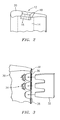
- FIG. 3 is a representation of a prepared turbine engine blade with a refractory metal core inserted into a damaged area of the trailing edge.
- Like reference numbers and designations in the various drawings indicate like elements.
- In accordance with the present invention, a process is provided for repairing a turbine engine component, such as a turbine blade or vane, formed from a superalloy material, such as a nickel-based or cobalt-based alloy, and used in a gas turbine engine. A disclosed process broadly comprises placing a piece of refractory metal material over the area of the component to be repaired and depositing a repair filler metal material proximate to and around the refractory metal material in an amount sufficient to fill in the space being repaired and welding same. The repair filler metal material beads and flows over the refractory metal material. Successive beading of the repair filler metal material, i.e., repetitive heating via a welding operation, eventually covers the entire refractory metal material and allows the operator to rebuild the blade or vane walls and tip. Throughout the process the refractory metal material does not experience direct exposure to the heat from the successive welding operations.
- Referring now to FIG. 2, a
tip 20 of a turbine blade to be repaired is illustrated. Theblade tip 20 has anarea 12 to be repaired. Theblade tip 20 has an openinternal cooling cavity 14 in the area to be repaired. Thearea 12 has been prepped in order to be repaired as known to one of ordinary skill in the art. The turbine blade may be mounted within a fixture (not shown) having a port. Once mounted, theinternal cavity 14 of the turbine blade is in communication with the port. An inert gas may then be introduced to purge theinternal cavity 14. - A
piece 16 of backing material formed from a refractory metal material may be positioned over thearea 12 to be repaired. The refractory metal material preferably has a melting point in excess of 1455°C (2651°F) and most preferably a melting point in excess of 1650°C (3000°F). Suitable refractory metals for the backing material may include, niobium, tantalum, molybdenum, tungsten, metals having a melting point higher than the melting point of the aforementioned superalloy materials, such as platinum, iridium, and the like, and their alloys. The refractory metal backing material may be uncoated or coated. - After the refractory metal material has been positioned in the
area 12, a repairfiller metal material 18 is deposited over thebacking material 16 and subjected to a welding operation. The repair filler metal material is preferably deposited in an amount sufficient to cover at least a portion of the refractory metal material, and preferably theentire piece 16 of refractory metal material. The repairfiller metal material 18 may comprise a cobalt based material, such as MERL 72, or a nickel based material, such as INCO 625, Rene 142, PWA 1440, and PWA 36946. Alternatively, the repairfiller metal material 18 may be a filler metal of the base alloy composition. The repairfiller metal material 18 may be applied using any suitable low heat input welding technique known in the art such as laser powder deposition, laser wire deposition, plasma arc welding- wire and powder, automated gas tungsten arc welding, combinations comprising at least one of the foregoing techniques, and the like. - Optionally, the refractory metal material may be uncoated or coated. If heat input of the repair is high, a diffusion barrier coating can be applied to the refractory metal material. Candidates include, but are not limited to, oxide ceramics such as alumina or mullite. If an oxide ceramic coating is used, an intermediate coating layer such as a silicide may be used to help coating adherence. When coated with ceramic, it is preferred to nickel plate over the alumina or mullite to aid in wetting the repair filler metal. The coating system may also include a nickel aluminide layer left behind after repair to improve the oxidation resistance of the coating. Alternatively, the refractory metal material may just be nickel plated using electrolytic nickel on at least one side if heat input is low. Alternatively, the refractory metal material may be chromium plated on at least one side if heat input is low. The presence of the coating enhances the wettability of the refractory metal material during the welding process.
- During the welding step, the heat input may be kept low to prevent the refractory metal material from alloying with the repair filler metal material. The welding operation may precisely melt and bead the repair filler metal material such that the bead flows over and solidifies to cover the refractory metal material. The welding operation is repeated as necessary to rebuild the blade walls and
tip 20. Throughout the welding process, the heat source is not applied directly to the refractory metal material. This prevents the refractory metal material from melting and alloying with the repair filler metal material and/or becoming distorted. Once the airfoil material is replaced, the blade tip cap (not shown) can be added in the same operation, thus eliminating the need for an additional welding operation. - Once the repair
filler metal material 18 has solidified, the refractory metal material may be removed by an acid chemical treatment using a nitric acid-sulfuric acid solution. For example, the solution may have about 2 parts nitric acid and about 1 part sulfuric acid added to about 2 parts water. The mixture is preferably heated to a temperature up to about 65°C (150°F) to increase the dissolution rate. - Alternatively, the refractory metal material may be removed using an oxidizing heat treatment in which air is flowed through the interior of the blade. The flowing air may be at a temperature in the range of about 760°C (1400°F) to about 900°C (1650°F) and may be flowed through the blade interior for a time in the range of from about 1 to about 4 hours. The oxidizing heat treatment may be performed, for example, either in a furnace, by direct resistant heating, by induction heating, or by a direct light source such as quartz lamps, lasers, infrared sources.
- Referring now to FIG. 3, a process for repairing a trailing
edge 30 of a turbine blade is illustrated. Apiece 32 of refractory metal material is first cut to conform to the shape of the blade trailing edge and anyinternal cavity 36 therein. Any suitable cutting technique known to one of ordinary skill in the art such as laser cutting, photo etching, stamping, or water jet cutting may be used to cut the refractory metal material. The refractory metal material may be one of the aforementioned materials and may be coated or uncoated as known to one of ordinary skill in the art. Thepiece 32 of refractory metal material, preferably in foil form, may be placed over thearea 34 to be repaired. One of the aforementioned repairfiller metal materials 38 may then deposited proximate to the piece ofrefractory material 32 and subjected to a welding treatment. - During the welding treatment, the heat input may be kept low to prevent the refractory metal material from alloying with the repair
filler metal material 38. The welding operation may precisely melt and bead the repairfiller metal material 38 such that the bead flows over and solidifies to cover the refractory metal material. The welding operation is repeated as necessary to re-establish the blade trailing edge including itsinternal cavity 36. Throughout the welding process, the heat source is not applied directly to the refractory metal material. This prevents the refractory metal material from melting and alloying with the repair filler metal material and/or becoming distorted. - After the repair filler metal material has solidified, the refractory metal backing material may be removed using either an acid chemical treatment, such as that described above, or an oxidizing heat treatment, such as that described above.
- The present invention is advantageous in that it eliminates the direct heating of the refractory metal material insert. This prevents alloying with the repair filler metal material and/or distortion of the refractory metal material. Due to the prevention of alloying and/or distortion, the refractory metal material can later be removed without the need for extensive post welding blend processing or machining such as EDM machining. This process also facilitates repairing the airfoil and replacing the blade tip cap can be performed in a single operation thus also increasing the turn time in repairing the component. Lastly, the process has particular utility in the repair of investment castings.
- One or more embodiments of the present invention have been described. Nevertheless, it will be understood that various modifications may be made without departing from the scope of the invention. Accordingly, other embodiments are within the scope of the following claims.
Claims (31)
- A process for repairing a component (20;30), comprising:placing a piece (16;32) of refractory metal material over an area (12;34) of a component to be repaired;depositing a repair filler metal material (18;38) proximate to said piece of refractory metal material (16;32) in an amount sufficient to repair said component;subjecting said repair filler material (18;38) to a welding treatment without directly heating said piece of refractory metal material (16;32);flowing said repair filler material (18;38) within said area (12;34); andcasting said repair filler material (18;38).
- The process according to claim 1, wherein said placing step comprises placing a piece of refractory metal material (16;32) formed from a refractory metal material selected from the group consisting of niobium, tantalum, molybdenum, tungsten, a metal having a melting point higher than the melting point of a superalloy, and alloys thereof over said area.
- The process according to claim 1 or 2, wherein said placing step comprises placing a piece of refractory metal material (16;32) having a melting point in excess of about 1650°C over said area.
- The process according to claim 3, wherein said refractory metal material (16;32) has a melting point in excess of about 1455°C.
- The process according to any preceding claim, wherein said component comprises a component for a turbine engine having at least one internal cavity (14;36).
- The process according to any preceding claim, wherein said refractory metal material is a cut foil (16; 32) which conforms to a shape of at least one internal cavity (14; 36) in said component (20).
- The process according to any preceding claim, wherein said placing step comprises placing said piece of refractory metal material (16;32) over an area (12;34) of an investment cast component to be repaired.
- The process according to any preceding claim, wherein said placing step comprises placing a piece of refractory metal material (16;32) having a nickel plating on at least one surface over said area (12;34).
- The process according to any of claims 1 to 7, wherein said placing step comprises placing a piece of refractory metal material (16;32) having a chromium coating on at least one surface over said area (12;34).
- The process according to any preceding claim, wherein said placing step comprises placing a piece of refractory metal material (16;32) having a diffusion barrier coating.
- The process according to claim 10, wherein said placing step comprises placing a piece of refractory metal material (16;32) having a coating comprising an alumina or mullite coating.
- The process according to claim 10, wherein said placing step comprises placing a piece of refractory metal material (16;32) having an alumina or mullite coating layer and an intermediate silicide layer.
- The process according to claim 12, wherein said refractory metal material (16;32) further has a nickel plating over said outer layer.
- The process according to any preceding claim, prior to said placing step further comprising the steps of:preparing said component for repair;mounting said component within a fixture;purging with an inert gas said fixture and at least one internal cavity of said component.
- The process according to any preceding claim, further comprising repeating said subjecting, flowing and casting steps until completion of the repair of said component.
- A process for repairing a tip portion (20) of a turbine blade, comprising:positioning a refractory metal material (16) over an area (12) to be repaired of said turbine blade;depositing a repair filler metal material (18) proximate to said refractory metal material (16);welding said repair filler metal material (18) without directly heating said refractory metal material (16);flowing said repair filler metal material (18) within said area (12); andcasting said repair filler metal material (18).
- The process according to claim 16, wherein said positioning step comprises positioning a piece of refractory metal material (16) selected from the group consisting of niobium, tantalum, molybdenum, tungsten, a metal having a melting point higher than the melting point of a superalloy, and alloys thereof over said area (12) to be repaired.
- The process according to claim 16 or 17, wherein said positioning step comprises positioning a piece of refractory metal material (16) plated with a nickel containing material over said area (12) to be repaired.
- The process according to claim 16 or 17, wherein said positioning step comprises positioning a piece of refractory metal material (16) coated with a chromium containing material over said area (12) to be repaired.
- The process according to any of claims 16 to 19, wherein said positioning step comprises positioning a piece of refractory metal material (16) having an oxide ceramic coating layer, an intermediate layer of silicide, and a plated nickel outer layer over said area (12) to be repaired.
- The process according to any of claims 16 to 20, prior to said placing step further comprising the steps of:preparing said turbine blade for repair;mounting said turbine blade within a fixture;purging with an inert gas said fixture and at least one internal cavity (14) of said turbine blade.
- The process according to any of claims 16 to 21, further comprising repeating said subjecting step until completion of the repair of said turbine blade.
- A process for repairing a trailing edge of a turbine blade, comprising:cutting a refractory metal material foil (32) to conform to a trailing edge shape of a turbine blade;positioning said cut refractory metal material foil (32) over a portion (34) of said trailing edge to be repaired;applying a repair filler metal material (38) over said refractory metal material foil (32);welding said repair filler metal material (38) to effect said repair without directly heating said refractory metal material (32);flowing said repair filler metal material (38) within said portion (34); andcasting said repair filler metal material (38).
- The process according to claim 23, wherein said cutting step comprises cutting a foil material (32) formed from a refractory metal selected from the group consisting of niobium, tantalum, molybdenum, tungsten, a metal having a melting point higher than the melting point of nickel, and alloys thereof.
- The process according to claim 24, wherein said foil (32) material has a nickel plating thereon.
- The process according to claim 24, wherein said foil (32) material has a chromium coating thereon.
- The process according to claim 24, wherein said foil (32) material has a nickel plated ceramic coating thereon.
- The process according to any preceding claim, further comprising removing said refractory metal material (16;32) after said welding step has been completed using an acid chemical treatment.
- The process according to any of claims 1 to 27, further comprising removing said refractory metal material (16;32) after said welding step has been completed using an oxidizing heat treatment.
- The process according to any of claims 23 to 29, prior to said placing step further comprising the steps of:preparing said turbine blade for repair;mounting said turbine blade within a fixture;purging with an inert gas said fixture and at least one internal cavity of said turbine blade.
- The process according to any of claims 23 to 30, further comprising repeating said subjecting step until completion of the repair of said trailing edge of said turbine blade.
Applications Claiming Priority (1)
| Application Number | Priority Date | Filing Date | Title |
|---|---|---|---|
| US11/489,154 US20080017280A1 (en) | 2006-07-18 | 2006-07-18 | Process for repairing turbine engine components |
Publications (1)
| Publication Number | Publication Date |
|---|---|
| EP1880787A1 true EP1880787A1 (en) | 2008-01-23 |
Family
ID=38564423
Family Applications (1)
| Application Number | Title | Priority Date | Filing Date |
|---|---|---|---|
| EP07252471A Ceased EP1880787A1 (en) | 2006-07-18 | 2007-06-18 | Process for repairing turbine engine components |
Country Status (5)
| Country | Link |
|---|---|
| US (1) | US20080017280A1 (en) |
| EP (1) | EP1880787A1 (en) |
| JP (1) | JP2008023598A (en) |
| CN (1) | CN101108453A (en) |
| SG (1) | SG139612A1 (en) |
Cited By (6)
| Publication number | Priority date | Publication date | Assignee | Title |
|---|---|---|---|---|
| EP2347850A1 (en) * | 2010-01-26 | 2011-07-27 | Rolls-Royce plc | A method of restoring a metallic component |
| DE102010005863A1 (en) * | 2010-01-26 | 2011-07-28 | Lufthansa Technik AG, 22335 | Method for beam welding an object and corresponding beam catching means |
| EP2085573A3 (en) * | 2008-02-04 | 2012-01-25 | General Electric Company | Method for forming a steam turbine bucket with erosion durability |
| EP2447470A1 (en) * | 2010-11-02 | 2012-05-02 | Siemens Aktiengesellschaft | Component monitoring and method for operating a machine |
| EP2781691A1 (en) * | 2013-03-19 | 2014-09-24 | Alstom Technology Ltd | Method for reconditioning a hot gas path part of a gas turbine |
| RU2667110C1 (en) * | 2017-08-31 | 2018-09-14 | Акционерное общество "Научно-производственный центр газотурбостроения "Салют" (АО НПЦ газотурбостроения "Салют") | Turbomachines blades shrouds from heat-resistant nickel alloys reconstruction method |
Families Citing this family (29)
| Publication number | Priority date | Publication date | Assignee | Title |
|---|---|---|---|---|
| EP2207642A1 (en) * | 2007-10-08 | 2010-07-21 | Siemens Aktiengesellschaft | Preheating temperature during remelting |
| EP2078578A1 (en) * | 2008-01-10 | 2009-07-15 | Siemens Aktiengesellschaft | Soldering of holes, method for coating and soldered rods |
| US20140271974A1 (en) * | 2013-03-14 | 2014-09-18 | Honda Motor Co., Ltd. | Conforming cooling method and mold |
| CN102728987A (en) * | 2011-04-06 | 2012-10-17 | 福建省长兴船舶重工有限公司 | Method for repairing screw propeller blades of ship |
| CN102728986A (en) * | 2011-04-06 | 2012-10-17 | 福建省长兴船舶重工有限公司 | Method for repairing abraded anchor jaw |
| US9174314B2 (en) * | 2011-11-03 | 2015-11-03 | Siemens Energy, Inc. | Isothermal structural repair of superalloy components including turbine blades |
| US9186757B2 (en) * | 2012-05-09 | 2015-11-17 | Siemens Energy, Inc. | Method of providing a turbine blade tip repair |
| US20140117007A1 (en) * | 2012-10-29 | 2014-05-01 | General Electric Company | Local Heat Treatment and Thermal Management System for Engine Components |
| CN105246644A (en) * | 2013-01-31 | 2016-01-13 | 西门子能源公司 | Localized repair of superalloy component |
| EP2964888B1 (en) * | 2013-03-04 | 2019-04-03 | Rolls-Royce North American Technologies, Inc. | Method for making gas turbine engine ceramic matrix composite airfoil |
| CN103386582A (en) * | 2013-07-31 | 2013-11-13 | 海门市柯成汽车零部件制造有限公司 | Defect repairing process for metal casting |
| ES2710226T3 (en) | 2013-10-30 | 2019-04-23 | United Technologies Corp | Reprocessing by welding by laser powder deposition for weldable nickel castings without fusion of the base metal belonging to gas turbine engines |
| US10328526B2 (en) | 2013-10-30 | 2019-06-25 | United Technologies Corporation | Laser powder deposition weld rework for gas turbine engine non-fusion weldable nickel castings |
| US10669867B2 (en) | 2013-12-10 | 2020-06-02 | Raytheon Technologies Corporation | Electrodeposited nickel-chromium alloy |
| WO2015088876A1 (en) | 2013-12-10 | 2015-06-18 | Lei Chen | Nickel-chromium-aluminum composite by electrodeposition |
| CN103831574B (en) * | 2013-12-10 | 2016-03-23 | 贵州黎阳航空动力有限公司 | Hollow turbine vane blade blanking cover renovation technique |
| US10378118B2 (en) | 2013-12-11 | 2019-08-13 | United Technologies Corporation | Electroformed nickel-chromium alloy |
| US20150165569A1 (en) * | 2013-12-18 | 2015-06-18 | Petya M. Georgieva | Repair of turbine engine components using waterjet ablation process |
| EP2949418B1 (en) | 2014-05-30 | 2017-02-01 | General Electric Technology GmbH | Method for repairing a turbine blade tip |
| CN105081671A (en) * | 2015-09-14 | 2015-11-25 | 沈阳飞机工业(集团)有限公司 | Local attaching piece repairing method for metal tool |
| CN106513958A (en) * | 2016-11-29 | 2017-03-22 | 沈阳黎明航空发动机(集团)有限责任公司 | Precise repairing method for inner ring of guide vane |
| US10767502B2 (en) | 2016-12-23 | 2020-09-08 | Rolls-Royce Corporation | Composite turbine vane with three-dimensional fiber reinforcements |
| CN108372387A (en) * | 2017-01-04 | 2018-08-07 | 中国航空制造技术研究院 | A kind of engine blade patching type restorative procedure |
| EP3584424B1 (en) * | 2017-05-30 | 2022-08-10 | Tpr Co., Ltd. | Method for manufacturing supercharger compressor housing |
| CN109570900A (en) * | 2018-11-23 | 2019-04-05 | 成都国营锦江机器厂 | The replacing options of straightener blade in engine |
| CN111172530A (en) * | 2020-01-17 | 2020-05-19 | 江苏理工学院 | Method for repairing silicide coating on surface of Mo alloy sheet |
| CN112122876A (en) * | 2020-08-31 | 2020-12-25 | 镇江同舟螺旋桨有限公司 | Surface corrosion repairing method for propeller blade of marine propeller |
| CN114367783A (en) * | 2022-01-10 | 2022-04-19 | 广东韶钢松山股份有限公司 | Maintenance method for fan vibration |
| KR102631599B1 (en) * | 2023-08-28 | 2024-02-01 | 터보파워텍(주) | Method of repairing wide gap cracks in hot gas path parts for gas turbine using brazing |
Citations (2)
| Publication number | Priority date | Publication date | Assignee | Title |
|---|---|---|---|---|
| US3986243A (en) * | 1975-09-22 | 1976-10-19 | Fansteel Inc. | Method of repairing chemical process equipment |
| EP1371439A1 (en) * | 2002-06-10 | 2003-12-17 | United Technologies Corporation | Method of weld repairing a component with a refractory metal backing material |
Family Cites Families (5)
| Publication number | Priority date | Publication date | Assignee | Title |
|---|---|---|---|---|
| US6158955A (en) * | 1999-06-03 | 2000-12-12 | General Electric Company | Welding method and assembly therefor |
| US7028881B2 (en) * | 2003-09-18 | 2006-04-18 | Siemens Power Generation, Inc. | Method for providing removable weld backing |
| US20060248718A1 (en) * | 2005-05-06 | 2006-11-09 | United Technologies Corporation | Superalloy repair methods and inserts |
| US20070044306A1 (en) * | 2005-08-29 | 2007-03-01 | United Technologies Corporation | Superalloy repair methods |
| SG134184A1 (en) * | 2006-01-16 | 2007-08-29 | United Technologies Corp | Chordwidth restoration of a trailing edge of a turbine airfoil by laser clad |
-
2006
- 2006-07-18 US US11/489,154 patent/US20080017280A1/en not_active Abandoned
-
2007
- 2007-03-14 SG SG200701911-0A patent/SG139612A1/en unknown
- 2007-06-18 EP EP07252471A patent/EP1880787A1/en not_active Ceased
- 2007-07-02 JP JP2007173632A patent/JP2008023598A/en active Pending
- 2007-07-18 CN CNA2007101366320A patent/CN101108453A/en active Pending
Patent Citations (2)
| Publication number | Priority date | Publication date | Assignee | Title |
|---|---|---|---|---|
| US3986243A (en) * | 1975-09-22 | 1976-10-19 | Fansteel Inc. | Method of repairing chemical process equipment |
| EP1371439A1 (en) * | 2002-06-10 | 2003-12-17 | United Technologies Corporation | Method of weld repairing a component with a refractory metal backing material |
Cited By (11)
| Publication number | Priority date | Publication date | Assignee | Title |
|---|---|---|---|---|
| EP2085573A3 (en) * | 2008-02-04 | 2012-01-25 | General Electric Company | Method for forming a steam turbine bucket with erosion durability |
| EP2347850A1 (en) * | 2010-01-26 | 2011-07-27 | Rolls-Royce plc | A method of restoring a metallic component |
| DE102010005863A1 (en) * | 2010-01-26 | 2011-07-28 | Lufthansa Technik AG, 22335 | Method for beam welding an object and corresponding beam catching means |
| US8387853B2 (en) | 2010-01-26 | 2013-03-05 | Rolls-Royce, Plc | Method of restoring a metallic component |
| DE102010005863B4 (en) * | 2010-01-26 | 2017-02-16 | Lufthansa Technik Ag | Method for beam welding an object and corresponding beam catching means |
| EP2447470A1 (en) * | 2010-11-02 | 2012-05-02 | Siemens Aktiengesellschaft | Component monitoring and method for operating a machine |
| WO2012059324A3 (en) * | 2010-11-02 | 2013-10-24 | Siemens Aktiengesellschaft | Method for component testing and for operating a machine |
| EP2781691A1 (en) * | 2013-03-19 | 2014-09-24 | Alstom Technology Ltd | Method for reconditioning a hot gas path part of a gas turbine |
| WO2014146829A1 (en) * | 2013-03-19 | 2014-09-25 | Alstom Technology Ltd | Method for reconditioning a hot gas path part of a gas turbine |
| US9926785B2 (en) | 2013-03-19 | 2018-03-27 | Ansaldo Energia Ip Uk Limited | Method for reconditioning a hot gas path part of a gas turbine |
| RU2667110C1 (en) * | 2017-08-31 | 2018-09-14 | Акционерное общество "Научно-производственный центр газотурбостроения "Салют" (АО НПЦ газотурбостроения "Салют") | Turbomachines blades shrouds from heat-resistant nickel alloys reconstruction method |
Also Published As
| Publication number | Publication date |
|---|---|
| SG139612A1 (en) | 2008-02-29 |
| JP2008023598A (en) | 2008-02-07 |
| CN101108453A (en) | 2008-01-23 |
| US20080017280A1 (en) | 2008-01-24 |
Similar Documents
| Publication | Publication Date | Title |
|---|---|---|
| US20080017280A1 (en) | Process for repairing turbine engine components | |
| EP1371439B1 (en) | Method of weld repairing a component for a turbine engine with a refractory metal backing material | |
| US8726501B2 (en) | Method of welding single crystal turbine blade tips with an oxidation-resistant filler material | |
| EP1721697B1 (en) | Superalloy repair methods and inserts | |
| TW527251B (en) | Weld repair of directionally solidified articles | |
| JP4375930B2 (en) | Laser cladding of turbine engine blade base plate | |
| CN100420537C (en) | Methods of Welding Repaired Parts | |
| US7250081B2 (en) | Methods for repair of single crystal superalloys by laser welding and products thereof | |
| EP3345718B1 (en) | Structure braze repair of hard-to-weld superalloy components using diffusion alloy insert | |
| JP3218567B2 (en) | Welding of high-strength nickel-base superalloys. | |
| JP2897803B2 (en) | Method for forming a coating on a superalloy part | |
| US7093335B2 (en) | Coated article and method for repairing a coated surface | |
| JP2003507614A (en) | How to Replace Airfoil on Turbine Blade | |
| JPH06210433A (en) | Method of initiating growth of a member from molten material, method of providing an extension at the end of a part, and repair of an airfoil shaped tip of a damaged part, and part | |
| JP2007062005A (en) | Superalloy repair method | |
| EP1788196B1 (en) | Methods for repairing gas turbine engine components | |
| Miglietti et al. | Repair process technology development and experience for w501f row 1 hot gas path blades |
Legal Events
| Date | Code | Title | Description |
|---|---|---|---|
| PUAI | Public reference made under article 153(3) epc to a published international application that has entered the european phase |
Free format text: ORIGINAL CODE: 0009012 |
|
| AK | Designated contracting states |
Kind code of ref document: A1 Designated state(s): AT BE BG CH CY CZ DE DK EE ES FI FR GB GR HU IE IS IT LI LT LU LV MC MT NL PL PT RO SE SI SK TR |
|
| AX | Request for extension of the european patent |
Extension state: AL BA HR MK YU |
|
| 17P | Request for examination filed |
Effective date: 20080617 |
|
| 17Q | First examination report despatched |
Effective date: 20080718 |
|
| AKX | Designation fees paid |
Designated state(s): DE GB |
|
| STAA | Information on the status of an ep patent application or granted ep patent |
Free format text: STATUS: THE APPLICATION HAS BEEN REFUSED |
|
| 18R | Application refused |
Effective date: 20160623 |
|
| RAP1 | Party data changed (applicant data changed or rights of an application transferred) |
Owner name: UNITED TECHNOLOGIES CORPORATION |