EP1880754B1 - Carbon dioxide capture system - Google Patents
Carbon dioxide capture system Download PDFInfo
- Publication number
- EP1880754B1 EP1880754B1 EP07112292A EP07112292A EP1880754B1 EP 1880754 B1 EP1880754 B1 EP 1880754B1 EP 07112292 A EP07112292 A EP 07112292A EP 07112292 A EP07112292 A EP 07112292A EP 1880754 B1 EP1880754 B1 EP 1880754B1
- Authority
- EP
- European Patent Office
- Prior art keywords
- carbon dioxide
- fluid
- separation system
- dioxide separation
- accordance
- Prior art date
- Legal status (The legal status is an assumption and is not a legal conclusion. Google has not performed a legal analysis and makes no representation as to the accuracy of the status listed.)
- Ceased
Links
- CURLTUGMZLYLDI-UHFFFAOYSA-N Carbon dioxide Chemical compound O=C=O CURLTUGMZLYLDI-UHFFFAOYSA-N 0.000 title claims description 140
- 229910002092 carbon dioxide Inorganic materials 0.000 title claims description 108
- 239000001569 carbon dioxide Substances 0.000 title claims description 96
- 239000012530 fluid Substances 0.000 claims description 32
- 238000000926 separation method Methods 0.000 claims description 28
- 239000012528 membrane Substances 0.000 claims description 18
- 239000000463 material Substances 0.000 claims description 17
- 229910052799 carbon Inorganic materials 0.000 claims description 10
- OKTJSMMVPCPJKN-UHFFFAOYSA-N Carbon Chemical compound [C] OKTJSMMVPCPJKN-UHFFFAOYSA-N 0.000 claims description 8
- 229910052751 metal Inorganic materials 0.000 claims description 6
- 239000002184 metal Substances 0.000 claims description 6
- -1 esthers Chemical class 0.000 claims description 5
- 238000004519 manufacturing process Methods 0.000 claims description 5
- VYPSYNLAJGMNEJ-UHFFFAOYSA-N Silicium dioxide Chemical compound O=[Si]=O VYPSYNLAJGMNEJ-UHFFFAOYSA-N 0.000 claims description 4
- 239000002608 ionic liquid Substances 0.000 claims description 4
- 229930195733 hydrocarbon Natural products 0.000 claims description 3
- 150000002430 hydrocarbons Chemical class 0.000 claims description 3
- 239000004941 mixed matrix membrane Substances 0.000 claims description 3
- 230000001737 promoting effect Effects 0.000 claims description 3
- 239000010457 zeolite Substances 0.000 claims description 3
- 150000001298 alcohols Chemical class 0.000 claims description 2
- 238000004891 communication Methods 0.000 claims description 2
- 150000002170 ethers Chemical class 0.000 claims description 2
- 150000002576 ketones Chemical class 0.000 claims description 2
- 230000035699 permeability Effects 0.000 claims description 2
- 239000003507 refrigerant Substances 0.000 claims description 2
- 239000000377 silicon dioxide Substances 0.000 claims description 2
- 150000002894 organic compounds Chemical class 0.000 claims 1
- 239000007800 oxidant agent Substances 0.000 claims 1
- 239000007789 gas Substances 0.000 description 31
- XLYOFNOQVPJJNP-UHFFFAOYSA-N water Substances O XLYOFNOQVPJJNP-UHFFFAOYSA-N 0.000 description 9
- 230000005611 electricity Effects 0.000 description 8
- 238000000034 method Methods 0.000 description 7
- GQPLMRYTRLFLPF-UHFFFAOYSA-N Nitrous Oxide Chemical compound [O-][N+]#N GQPLMRYTRLFLPF-UHFFFAOYSA-N 0.000 description 4
- 239000011148 porous material Substances 0.000 description 4
- 230000008569 process Effects 0.000 description 4
- QAOWNCQODCNURD-UHFFFAOYSA-N Sulfuric acid Chemical compound OS(O)(=O)=O QAOWNCQODCNURD-UHFFFAOYSA-N 0.000 description 3
- 238000005516 engineering process Methods 0.000 description 3
- 238000000605 extraction Methods 0.000 description 3
- 239000000446 fuel Substances 0.000 description 3
- 239000007788 liquid Substances 0.000 description 3
- 239000000126 substance Substances 0.000 description 3
- QGZKDVFQNNGYKY-UHFFFAOYSA-N Ammonia Chemical compound N QGZKDVFQNNGYKY-UHFFFAOYSA-N 0.000 description 2
- IJGRMHOSHXDMSA-UHFFFAOYSA-N Atomic nitrogen Chemical compound N#N IJGRMHOSHXDMSA-UHFFFAOYSA-N 0.000 description 2
- LFQSCWFLJHTTHZ-UHFFFAOYSA-N Ethanol Chemical compound CCO LFQSCWFLJHTTHZ-UHFFFAOYSA-N 0.000 description 2
- GWEVSGVZZGPLCZ-UHFFFAOYSA-N Titan oxide Chemical compound O=[Ti]=O GWEVSGVZZGPLCZ-UHFFFAOYSA-N 0.000 description 2
- PNEYBMLMFCGWSK-UHFFFAOYSA-N aluminium oxide Inorganic materials [O-2].[O-2].[O-2].[Al+3].[Al+3] PNEYBMLMFCGWSK-UHFFFAOYSA-N 0.000 description 2
- 230000006835 compression Effects 0.000 description 2
- 238000007906 compression Methods 0.000 description 2
- 238000009833 condensation Methods 0.000 description 2
- 230000005494 condensation Effects 0.000 description 2
- 239000000470 constituent Substances 0.000 description 2
- 238000009792 diffusion process Methods 0.000 description 2
- 239000011147 inorganic material Substances 0.000 description 2
- 239000010954 inorganic particle Substances 0.000 description 2
- 239000001272 nitrous oxide Substances 0.000 description 2
- 238000011084 recovery Methods 0.000 description 2
- 230000009919 sequestration Effects 0.000 description 2
- 238000001179 sorption measurement Methods 0.000 description 2
- RWSOTUBLDIXVET-UHFFFAOYSA-N Dihydrogen sulfide Chemical compound S RWSOTUBLDIXVET-UHFFFAOYSA-N 0.000 description 1
- 235000019738 Limestone Nutrition 0.000 description 1
- 229910021536 Zeolite Inorganic materials 0.000 description 1
- 239000006096 absorbing agent Substances 0.000 description 1
- 238000010521 absorption reaction Methods 0.000 description 1
- 239000002253 acid Substances 0.000 description 1
- 239000003463 adsorbent Substances 0.000 description 1
- 150000001412 amines Chemical class 0.000 description 1
- 229910021529 ammonia Inorganic materials 0.000 description 1
- QVGXLLKOCUKJST-UHFFFAOYSA-N atomic oxygen Chemical compound [O] QVGXLLKOCUKJST-UHFFFAOYSA-N 0.000 description 1
- 238000009835 boiling Methods 0.000 description 1
- 239000001273 butane Substances 0.000 description 1
- 239000006227 byproduct Substances 0.000 description 1
- 238000001354 calcination Methods 0.000 description 1
- 239000000919 ceramic Substances 0.000 description 1
- 230000008859 change Effects 0.000 description 1
- 230000002301 combined effect Effects 0.000 description 1
- 238000002485 combustion reaction Methods 0.000 description 1
- 229910052878 cordierite Inorganic materials 0.000 description 1
- GDVKFRBCXAPAQJ-UHFFFAOYSA-A dialuminum;hexamagnesium;carbonate;hexadecahydroxide Chemical compound [OH-].[OH-].[OH-].[OH-].[OH-].[OH-].[OH-].[OH-].[OH-].[OH-].[OH-].[OH-].[OH-].[OH-].[OH-].[OH-].[Mg+2].[Mg+2].[Mg+2].[Mg+2].[Mg+2].[Mg+2].[Al+3].[Al+3].[O-]C([O-])=O GDVKFRBCXAPAQJ-UHFFFAOYSA-A 0.000 description 1
- JSKIRARMQDRGJZ-UHFFFAOYSA-N dimagnesium dioxido-bis[(1-oxido-3-oxo-2,4,6,8,9-pentaoxa-1,3-disila-5,7-dialuminabicyclo[3.3.1]nonan-7-yl)oxy]silane Chemical compound [Mg++].[Mg++].[O-][Si]([O-])(O[Al]1O[Al]2O[Si](=O)O[Si]([O-])(O1)O2)O[Al]1O[Al]2O[Si](=O)O[Si]([O-])(O1)O2 JSKIRARMQDRGJZ-UHFFFAOYSA-N 0.000 description 1
- HNPSIPDUKPIQMN-UHFFFAOYSA-N dioxosilane;oxo(oxoalumanyloxy)alumane Chemical compound O=[Si]=O.O=[Al]O[Al]=O HNPSIPDUKPIQMN-UHFFFAOYSA-N 0.000 description 1
- 239000003344 environmental pollutant Substances 0.000 description 1
- IXCSERBJSXMMFS-UHFFFAOYSA-N hcl hcl Chemical compound Cl.Cl IXCSERBJSXMMFS-UHFFFAOYSA-N 0.000 description 1
- 239000001257 hydrogen Substances 0.000 description 1
- 229910052739 hydrogen Inorganic materials 0.000 description 1
- 125000004435 hydrogen atom Chemical class [H]* 0.000 description 1
- 229910001701 hydrotalcite Inorganic materials 0.000 description 1
- 229960001545 hydrotalcite Drugs 0.000 description 1
- 230000006872 improvement Effects 0.000 description 1
- 229910010272 inorganic material Inorganic materials 0.000 description 1
- 230000010354 integration Effects 0.000 description 1
- 238000002955 isolation Methods 0.000 description 1
- 239000006028 limestone Substances 0.000 description 1
- 230000014759 maintenance of location Effects 0.000 description 1
- 239000011159 matrix material Substances 0.000 description 1
- 230000007246 mechanism Effects 0.000 description 1
- 239000002923 metal particle Substances 0.000 description 1
- 150000002739 metals Chemical class 0.000 description 1
- 239000012229 microporous material Substances 0.000 description 1
- IJDNQMDRQITEOD-UHFFFAOYSA-N n-butane Chemical compound CCCC IJDNQMDRQITEOD-UHFFFAOYSA-N 0.000 description 1
- OFBQJSOFQDEBGM-UHFFFAOYSA-N n-pentane Natural products CCCCC OFBQJSOFQDEBGM-UHFFFAOYSA-N 0.000 description 1
- 229910052757 nitrogen Inorganic materials 0.000 description 1
- 239000001301 oxygen Substances 0.000 description 1
- 229910052760 oxygen Inorganic materials 0.000 description 1
- 231100000719 pollutant Toxicity 0.000 description 1
- 239000002861 polymer material Substances 0.000 description 1
- 230000009467 reduction Effects 0.000 description 1
- 239000000758 substrate Substances 0.000 description 1
- 239000003643 water by type Substances 0.000 description 1
Images


Classifications
-
- B—PERFORMING OPERATIONS; TRANSPORTING
- B01—PHYSICAL OR CHEMICAL PROCESSES OR APPARATUS IN GENERAL
- B01D—SEPARATION
- B01D53/00—Separation of gases or vapours; Recovering vapours of volatile solvents from gases; Chemical or biological purification of waste gases, e.g. engine exhaust gases, smoke, fumes, flue gases, aerosols
- B01D53/22—Separation of gases or vapours; Recovering vapours of volatile solvents from gases; Chemical or biological purification of waste gases, e.g. engine exhaust gases, smoke, fumes, flue gases, aerosols by diffusion
- B01D53/229—Integrated processes (Diffusion and at least one other process, e.g. adsorption, absorption)
-
- B—PERFORMING OPERATIONS; TRANSPORTING
- B01—PHYSICAL OR CHEMICAL PROCESSES OR APPARATUS IN GENERAL
- B01D—SEPARATION
- B01D53/00—Separation of gases or vapours; Recovering vapours of volatile solvents from gases; Chemical or biological purification of waste gases, e.g. engine exhaust gases, smoke, fumes, flue gases, aerosols
- B01D53/14—Separation of gases or vapours; Recovering vapours of volatile solvents from gases; Chemical or biological purification of waste gases, e.g. engine exhaust gases, smoke, fumes, flue gases, aerosols by absorption
- B01D53/1456—Removing acid components
- B01D53/1475—Removing carbon dioxide
-
- B—PERFORMING OPERATIONS; TRANSPORTING
- B01—PHYSICAL OR CHEMICAL PROCESSES OR APPARATUS IN GENERAL
- B01D—SEPARATION
- B01D53/00—Separation of gases or vapours; Recovering vapours of volatile solvents from gases; Chemical or biological purification of waste gases, e.g. engine exhaust gases, smoke, fumes, flue gases, aerosols
- B01D53/22—Separation of gases or vapours; Recovering vapours of volatile solvents from gases; Chemical or biological purification of waste gases, e.g. engine exhaust gases, smoke, fumes, flue gases, aerosols by diffusion
-
- B—PERFORMING OPERATIONS; TRANSPORTING
- B01—PHYSICAL OR CHEMICAL PROCESSES OR APPARATUS IN GENERAL
- B01D—SEPARATION
- B01D2257/00—Components to be removed
- B01D2257/50—Carbon oxides
- B01D2257/504—Carbon dioxide
-
- Y—GENERAL TAGGING OF NEW TECHNOLOGICAL DEVELOPMENTS; GENERAL TAGGING OF CROSS-SECTIONAL TECHNOLOGIES SPANNING OVER SEVERAL SECTIONS OF THE IPC; TECHNICAL SUBJECTS COVERED BY FORMER USPC CROSS-REFERENCE ART COLLECTIONS [XRACs] AND DIGESTS
- Y02—TECHNOLOGIES OR APPLICATIONS FOR MITIGATION OR ADAPTATION AGAINST CLIMATE CHANGE
- Y02C—CAPTURE, STORAGE, SEQUESTRATION OR DISPOSAL OF GREENHOUSE GASES [GHG]
- Y02C20/00—Capture or disposal of greenhouse gases
- Y02C20/40—Capture or disposal of greenhouse gases of CO2
-
- Y—GENERAL TAGGING OF NEW TECHNOLOGICAL DEVELOPMENTS; GENERAL TAGGING OF CROSS-SECTIONAL TECHNOLOGIES SPANNING OVER SEVERAL SECTIONS OF THE IPC; TECHNICAL SUBJECTS COVERED BY FORMER USPC CROSS-REFERENCE ART COLLECTIONS [XRACs] AND DIGESTS
- Y02—TECHNOLOGIES OR APPLICATIONS FOR MITIGATION OR ADAPTATION AGAINST CLIMATE CHANGE
- Y02P—CLIMATE CHANGE MITIGATION TECHNOLOGIES IN THE PRODUCTION OR PROCESSING OF GOODS
- Y02P20/00—Technologies relating to chemical industry
- Y02P20/10—Process efficiency
- Y02P20/129—Energy recovery, e.g. by cogeneration, H2recovery or pressure recovery turbines
Definitions
- This invention relates generally to carbon capture and more specifically to methods and systems for capturing carbon dioxide.
- CO 2 carbon dioxide
- H 2 hydrogen
- CO 2 is currently recovered from combustion exhaust by using, for example, amine absorbers and cryogenic coolers. Examples of the recovery of CO2 can be found ini WO 2004/069739 , EP 1733781 , WO98/13124 , WO02/074421 and WO03/00807
- the cost of CO 2 capture using current technology can be as high as $150 per ton - much too high for carbon emissions reduction applications.
- carbon dioxide capture is generally estimated to represent three fourths of the total cost of a carbon capture, storage, transport, and sequestration system.
- the invention is defined by claim 1.
- a carbon dioxide separation system 10 comprises a first flow path 12 for directing a fluid comprising carbon dioxide 14 therethrough and a second flow path 16 for directing a sweep fluid 18 therethrough, and a separator 20, for example a membrane, for separating the first and second flow paths (12, 16) and for promoting carbon dioxide transport therebetween (along the path of the arrows), as shown in FIG. 1 .
- Separator 20 comprises a material or structure that enables selective permeability of carbon dioxide. Any suitable material may be used for the separator 20 provided that that material is stable at the operating conditions and has the required permeance and selectivity at those conditions.
- Materials known to be selective for CO 2 include, for example, certain inorganic and polymer materials. Inorganic materials include microporous alumina, microporous carbon, microporous silica, microporous perovskite, zeolite and hydrotalcite materials.
- mechanisms for CO 2 selectivity in microporous materials include surface diffusion and capillary condensation.
- a material that has an affinity for CO 2 relative to other gases in a stream will show a preferred adsorption and surface diffusion of CO 2 .
- the presence of the adsorbed CO 2 molecules, through capillary condensation will effectively block the pore from the more weakly adsorbing gases, thereby hindering their transport.
- the performance properties of such inorganic membranes at a given operating condition can be improved by a person skilled in the art by modifying the surface, altering the pore size or changing the composition of the membrane.
- Hybrid membranes that incorporate inorganic particles within a polymeric matrix can show enhanced CO 2 selectivity properties at elevated operating conditions.
- Mixed matrix membranes that incorporate adsorbent inorganic particles such as zeolites or carbon within polymeric matrices also show enhanced properties at elevated operating conditions.
- the invention is not restricted to any particular membrane material or type and encompasses any membrane comprising any material that is capable of providing suitable levels of permeance and selectivity. That includes, for example, mixed matrix membranes, facilitated transport membranes, ionic liquid membranes, and polymerized ionic liquid membranes.
- separator 20 often comprises a separation layer that is disposed upon a support layer.
- the porous support can comprise a material that is different from the separation layer.
- Support materials for asymmetric inorganic membranes include porous alumina, titania, cordierite, carbon and metals.
- the support material is a porous metal and the separation layer is disposed within the pores of the metal, rather than upon the surface of the metal substrate.
- Most materials that are suitable as selective layers are inorganic, ceramic, polymeric or combinations thereof, which have low thermal transport properties.
- the structure effectively provides the combined function of heat and selective mass transfer, with the connected porous network of high conductivity metal particles providing effective heat transfer and the separation layer disposed within the pores providing the selective mass transport.
- Separator 20 physically separates first flow path 12 and second flow path 16 and promotes carbon dioxide transport therebetween.
- a carbon dioxide separation unit 22 is in flow communication with second flow path 16 and receives the sweep fluid 18 8 and CO 2 to isolate the carbon dioxide 26 contained therein.
- the carbon dioxide 26 can be sequestered, stored, recirculated, used for additional processes or otherwise utilized after isolation and removal.
- Fluid comprising carbon dioxide 14 is an exhaust gas, for example, an exhaust gas having a temperature in the range between about 30° C to about 700° C.
- this invention can be utilized with fluids containing carbon dioxide 14 over a wide range of temperatures.
- This system can be utilized over a wide range of systems for any exhaust gas, for example, furnace exhaust, thermal oxidizers, metal processing or any other industrial process.
- fluids containing carbon dioxide 14 can be treated at ambient temperature with a suitable separator 20 and sweep fluid 18 being selected.
- Sweep fluid 18 is a condensable fluid, like steam for example.
- sweep fluid 18 can be one or more of the following: refrigerants; alcohols, like ethanol; hydrocarbons like butane; fluorinated and non-fluorinated hydrocarbons, ketones, esthers, and ethers; and siloxanes.
- refrigerants alcohols, like ethanol
- hydrocarbons like butane
- fluorinated and non-fluorinated hydrocarbons ketones, esthers, and ethers
- siloxanes siloxanes.
- a material selective to other constituents within an exhaust gas steam for example, CO, nitrous oxide (NOx), or acid gases like hydrogen sulfide (H 2 S), sulfuric acid (H 2 SO 4 ) or hydrochloric acid (HCl) or other pollutants or species, may be utilized to capture the other constituents in a similar fashion.
- a material selective to Oxygen can be used in a similar manner as described herein to help
- an exhaust gas 14 containing CO 2 is directed along first flow path 12 and a sweep steam flow 18 is directed along second flow path 16.
- the separator 20 is selective to CO 2 and as the sweep steam flow 18 has a significantly lower CO 2 partial pressure than that of the exhaust gas 14 containing CO 2 , the CO 2 is drawn into the sweep steam flow 18 through separator 20. Accordingly, the stream flowing out of first flow path 12 is a low-CO 2 content flow 26 that can be recycled or released to the atmosphere and the stream flowing out of second flow path 16 is a high-CO 2 content flow 28 that is directed to carbon dioxide separation unit 22 to separate and isolate the CO 2 24.
- the separator 22 is selective to CO 2 through principles of, for example, boiling point, chemical absorption or adsorption, molecular size, density, or the like.
- the gas temperatures may be from 30°C to about 1500° C, as specified and discussed herein.
- System 100 further comprises a steam turbine 102 for generating electricity via generator 104 and for generating a low-pressure steam sweep flow 118 (for example, having a pressure in the range between about 0.03 bar to about 10 bar), as shown in FIG.2 .
- the stream flowing out of second flow path 16 is a high-CO 2 content steam flow 128 that is directed to carbon dioxide separation unit 22 to separate and isolate the CO 2 24.
- carbon dioxide separation unit 22 is a condenser 122 that condenses the steam and isolates the non-condensable CO 2 for easy separation.
- the condensed steam (now water) is then directed, often via pump 129, through a heat recovery steam generator (HIZSG) 130 to produce steam 132 (for example, having a pressure between about 20 to about 130 bar and at a temperature between about 300° C to about 700° C) that is introduced into steam turbine 102.
- the low-pressure steam sweep flow 118 (for example, having a temperature between about 20° C to about 200° C) can also be used to cool the fluid comprising carbon dioxide 14 introduced via first flow path 12, if for example, the fluid 14 is a high temperature exhaust gas.
- This embodiment is particularly advantageous because the large driving force required for CO 2 removal can be obtained by using the low pressures typically associated at the exit of steam turbines, thus providing more efficient CO 2 removal. Integration of the steam cycles and the CO 2 removal system are feasible because steam cycles are typically co-located adjacent to CO 2 containing exhaust streams.
- System 200 further comprises a second steam turbine 202 for generating additional electricity via generator 204, as shown in FIG. 3 .
- the CO 2 flows across the separator 20 and into sweep flow 118.
- the sweep flow 118 (for example, having a pressure between about 1 bar to about 40 bar and at a temperature between about 100° C to about 450° C, and often between about 15 bar to about 30 bar and at a temperature between about 200° C to about 350° C) therefore, increases in volume due to the addition of the CO 2 .
- the high-CO 2 content steam flow 128 exiting second flow path will also have an increased temperature (for example in the range between about 400° C to about 600° C).
- This higher volume, higher temperature high-CO 2 content steam flow 128 is directed into second steam turbine 202 for the generation of additional electricity via generator 204.
- a slipstream of low-pressure steam 240 can be directed from the HRSG 130 to the second steam turbine 202 to boost the flow of the high-CO 2 content steam flow 128 as it enters second steam turbine 202 and recovers heat more efficiently in HRSG 130.
- This particular embodiment is advantageous as it combines both a CO 2 removal process with a reheat stage within the steam cycle.
- System 200 may optionally include an additional CO 2 cleanup unit 242 to remove any dissolved CO 2 from the water flowing out of condenser 122 prior to the waters entry into the HRSG 130.
- An additional CO 2 cleanup unit 242 to remove any dissolved CO 2 from the water flowing out of condenser 122 prior to the waters entry into the HRSG 130.
- One option for removal of the dissolved CO 2 from the water is stripping, for example, bringing the water flowing out of condenser 122 into contact with a gaseous stream, for example steam or air (not shown). Additionally, further chemical treatment may also be applied to remove carbon ions down to a lower level than is practical with a stripping process.
- an organic rankine cycle 302 is combined with a steam rankine cycle 304 as shown in FIG 4 .
- an organic rankine cycle (ORC) turbine 306 receives an organic vapor 308 and expands the vapor to power generator 310 to generate electricity and produces an organic sweep stream 312 that is directed along second flow path 16.
- ORC organic rankine cycle
- CO 2 passes from the fluid comprising carbon dioxide 14, for example exhaust gas, to the organic sweep stream 312 through separator 20 to produce a high high-CO 2 content flow 314.
- the high-CO 2 content flow 314 is directed to an organic fluid condenser 316 where the organic fluid carrier is condensed to an organic liquid 318 (for example, at a pressure between about 0.03 to about 10 bar and a temperature of between about 15° C to about 40° C) and the non-condensable CO 2 320 is separated out.
- organic fluid condenser 316 where the organic fluid carrier is condensed to an organic liquid 318 (for example, at a pressure between about 0.03 to about 10 bar and a temperature of between about 15° C to about 40° C) and the non-condensable CO 2 320 is separated out.
- the organic fluid 318 is directed, typically via a pump 322, to an organic vapor generator 324 where heat is applied to the organic fluid 318, and the organic fluid 318 undergoes a phase change to organic vapor 308.
- the organic vapor 308 is then directed to ORC turbine 306.
- the heat applied to the organic fluid 318 (for example, at a pressure between about 5 bar to about 50 bar) in the organic vapor generator 324 can be applied by a low-pressure steam flow 326 (for example, at a pressure between about 0.5 to about 10 bar).
- the low-pressure steam flow 326 is directed to the organic vapor generator 324 and is condensed to produce a water flow 328 (for example, having a temperature between about 70 to about 170°C).
- the heat is transferred from the low-pressure steam flow 326 to the organic liquid 318 thereby producing the organic vapor 308 (for example, having a temperature between about 65° C to about 165° C) and a water flow 328, respectively, in the two interconnected systems.
- the water flow 328 is directed, typically via a pump 330, to an HRSG 332 where the water is converted to a high temperature steam flow 334 (for example, having a pressure between about 20 to about 150 bar and a temperature between about 300° C to about 700° C).
- the high temperature steam flow 334 is expanded in a steam turbine 336 to produce electricity via generator 338 and low-pressure steam flow 326.
- This embodiment does not need to have any additional water treatment as the correct organic fluid will not contain dissolved CO 2 within it as a liquid.
- a gas turbine system 403 is included as shown in FIG. 5 .
- Air 401 is compressed in the compression section 402 and then mixed with a fuel 404 and combusted in combustor 406.
- the resulting high temperature gases 408 are expanded in turbine section 410 to generate electricity via generator 412 and an exhaust gas 414.
- the exhaust gas 414 is directed to an HRSG 416 where the heat from the exhaust gas 414 is used to generate additional electricity in a steam cycle or other bottoming cycle (not shown) and a reduced temperature exhaust gas 418 (for example, having a temperature in the range between about 50° C to about 100° C).
- a first portion 420 of the reduced temperature exhaust gas 418 can optionally be recycled back to mix with the air 401 that is introduced into compressor section 402 to increase the overall CO 2 content in the reduced temperature exhaust gas 418 and to improve the extraction efficiency of the system 400.
- the CO 2 content of reduced temperature exhaust gas 418 should be in the range between about 8% by volume to about 15% by volume for improved extraction efficiency through a carbon dioxide extraction system. In order to achieve these levels of CO 2 such technologies as exhaust gas recirculation can be employed.
- a second portion 422 of the reduced temperature exhaust gas 418 is directed into a first flow path 424 of a carbon dioxide separation system 426.
- a sweep fluid 428 is directed along a second flow path 426.
- a separator 20, for example a membrane, is positioned between first and second flow paths 424, 426 for separating the first and second flow paths 424, 426 and for promoting carbon dioxide transport therebetween (along the path of the arrows).
- a low-CO 2 content flow 427 is directed out of first flow path 424 to be recycled or released to the atmosphere and a high-CO 2 content flow 430 is directed to a carbon dioxide separation unit 432 to separate and isolate the CO 2 434.
- the exhaust gas 414 is directed into first flow path 424 of a carbon dioxide separation system 426 rather than through an intermediate HRSG.
- the separator 20 is compatible with high temperatures, for example, temperatures exceeding 500C.
- a gas turbine system 502 is included as shown in FIG. 7 .
- Air 504 is compressed in the compression section 506 and then mixed with a fuel 508 and combusted in combustor 510 (for example, having a pressure in the range between about 10 to about 60 bar, and often between about 15 to about 45 bar).
- the resulting high temperature gases 512 (for example, having a temperature in the range between about 1000° C to about 1600° C) are expanded in turbine section 514 to generate electricity via generator 516 and an exhaust gas 518.
- the combustor 510 is at least partially defined by separator 20. As the air 504 and fuel 508 combust within the combustor 510, CO 2 is generated. Due to the high pressure within combustor 510 and the low partial pressure of CO 2 present in a sweep stream 520 adjacent separator 20 (external to the combustor 510), the CO 2 migrates across separator 20 into sweep stream 520 thereby generating a high-CO 2 content flow 522 that is directed to a carbon dioxide separation unit 524 to separate and isolate the CO 2 526. Accordingly, the exhaust gas 518 has significantly reduced CO 2 levels.
Landscapes
- Chemical & Material Sciences (AREA)
- Engineering & Computer Science (AREA)
- Analytical Chemistry (AREA)
- General Chemical & Material Sciences (AREA)
- Oil, Petroleum & Natural Gas (AREA)
- Chemical Kinetics & Catalysis (AREA)
- Separation Using Semi-Permeable Membranes (AREA)
- Treating Waste Gases (AREA)
- Carbon And Carbon Compounds (AREA)
Description
- This invention relates generally to carbon capture and more specifically to methods and systems for capturing carbon dioxide.
- Before carbon dioxide (CO2) gas can be sequestered from power plants and other point sources, it must be captured in a relatively pure form. On a mass basis, CO2 is the nineteenth largest commodity chemical in the United States, and CO2 is routinely separated and captured as a byproduct of industrial processes such as synthetic ammonia production, hydrogen (H2) production or limestone calcination.
- Existing CO2 capture technologies, however, are not cost-effective when considered in the context of sequestering CO2 from power plants. Most power plants and other large point sources use air-fired combustors, a process that exhausts CO2 diluted with nitrogen. For efficient carbon sequestration, the CO2 in these exhaust gases must be separated and concentrated.
- CO2 is currently recovered from combustion exhaust by using, for example, amine absorbers and cryogenic coolers. Examples of the recovery of CO2 can be found ini
WO 2004/069739 ,EP 1733781 ,WO98/13124 WO02/074421 WO03/00807 - Accordingly, there is a need for a new CO2 separation system and method to make CO2 separation and capture from power plants easier and more cost effective.
- The invention is defined by claim 1.
- These and other features, aspects, and advantages of the present invention will become better understood when the following detailed description of embodiments provided by way of example is read with reference to the accompanying drawings in which like characters represent like parts throughout the drawings, wherein:
-
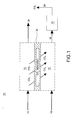
FIG. 1 . is a schematic depiction not according to the invention. -
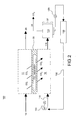
FIG. 2 . is another schematic depiction not according to the invention. -
FIG. 3 . is another schematic depiction not according to the invention. -
FIG. 4 . is another schematic depiction of not according to the instant invention. -
FIG. 5 is another schematic depiction not according to the invention. -
FIG. 6 is another schematic depiction not according to the invention. -
FIG. 7 is another schematic depiction not according to the invention. - A carbon
dioxide separation system 10 comprises afirst flow path 12 for directing a fluid comprisingcarbon dioxide 14 therethrough and asecond flow path 16 for directing asweep fluid 18 therethrough, and aseparator 20, for example a membrane, for separating the first and second flow paths (12, 16) and for promoting carbon dioxide transport therebetween (along the path of the arrows), as shown inFIG. 1 . -
Separator 20 comprises a material or structure that enables selective permeability of carbon dioxide. Any suitable material may be used for theseparator 20 provided that that material is stable at the operating conditions and has the required permeance and selectivity at those conditions. Materials known to be selective for CO2 include, for example, certain inorganic and polymer materials. Inorganic materials include microporous alumina, microporous carbon, microporous silica, microporous perovskite, zeolite and hydrotalcite materials. - While not to be limited by a particular theory, mechanisms for CO2 selectivity in microporous materials include surface diffusion and capillary condensation. A material that has an affinity for CO2 relative to other gases in a stream will show a preferred adsorption and surface diffusion of CO2. Furthermore, the presence of the adsorbed CO2 molecules, through capillary condensation, will effectively block the pore from the more weakly adsorbing gases, thereby hindering their transport. The performance properties of such inorganic membranes at a given operating condition can be improved by a person skilled in the art by modifying the surface, altering the pore size or changing the composition of the membrane. Hybrid membranes that incorporate inorganic particles within a polymeric matrix can show enhanced CO2 selectivity properties at elevated operating conditions. Mixed matrix membranes that incorporate adsorbent inorganic particles such as zeolites or carbon within polymeric matrices also show enhanced properties at elevated operating conditions. The invention is not restricted to any particular membrane material or type and encompasses any membrane comprising any material that is capable of providing suitable levels of permeance and selectivity. That includes, for example, mixed matrix membranes, facilitated transport membranes, ionic liquid membranes, and polymerized ionic liquid membranes. In practice,
separator 20 often comprises a separation layer that is disposed upon a support layer. - For asymmetric inorganic membranes, the porous support can comprise a material that is different from the separation layer. Support materials for asymmetric inorganic membranes include porous alumina, titania, cordierite, carbon and metals. In one embodiment the support material is a porous metal and the separation layer is disposed within the pores of the metal, rather than upon the surface of the metal substrate. Most materials that are suitable as selective layers are inorganic, ceramic, polymeric or combinations thereof, which have low thermal transport properties. In one embodiment, the structure effectively provides the combined function of heat and selective mass transfer, with the connected porous network of high conductivity metal particles providing effective heat transfer and the separation layer disposed within the pores providing the selective mass transport.
-
Separator 20 physically separatesfirst flow path 12 andsecond flow path 16 and promotes carbon dioxide transport therebetween. A carbondioxide separation unit 22 is in flow communication withsecond flow path 16 and receives thesweep fluid 18 8 and CO2 to isolate thecarbon dioxide 26 contained therein. Thecarbon dioxide 26 can be sequestered, stored, recirculated, used for additional processes or otherwise utilized after isolation and removal. - Fluid comprising
carbon dioxide 14 is an exhaust gas, for example, an exhaust gas having a temperature in the range between about 30° C to about 700° C. In addition, this invention can be utilized with fluids containingcarbon dioxide 14 over a wide range of temperatures. This system can be utilized over a wide range of systems for any exhaust gas, for example, furnace exhaust, thermal oxidizers, metal processing or any other industrial process. In fact, fluids containingcarbon dioxide 14 can be treated at ambient temperature with asuitable separator 20 and sweepfluid 18 being selected. - Sweep
fluid 18 is a condensable fluid, like steam for example. In another embodiment,sweep fluid 18 can be one or more of the following: refrigerants; alcohols, like ethanol; hydrocarbons like butane; fluorinated and non-fluorinated hydrocarbons, ketones, esthers, and ethers; and siloxanes. In addition, while this invention is discussed in relation to CO2 capture systems, a material selective to other constituents within an exhaust gas steam, for example, CO, nitrous oxide (NOx), or acid gases like hydrogen sulfide (H2S), sulfuric acid (H2SO4) or hydrochloric acid (HCl) or other pollutants or species, may be utilized to capture the other constituents in a similar fashion. In addition, a material selective to Oxygen can be used in a similar manner as described herein to help strip O2 in plants that require an Air Separation Unit (ASU). - Referring once again to
FIG. 1 , in one example, anexhaust gas 14 containing CO2 is directed alongfirst flow path 12 and asweep steam flow 18 is directed alongsecond flow path 16. Theseparator 20 is selective to CO2 and as thesweep steam flow 18 has a significantly lower CO2 partial pressure than that of theexhaust gas 14 containing CO2, the CO2 is drawn into thesweep steam flow 18 throughseparator 20. Accordingly, the stream flowing out offirst flow path 12 is a low-CO2 content flow 26 that can be recycled or released to the atmosphere and the stream flowing out ofsecond flow path 16 is a high-CO2 content flow 28 that is directed to carbondioxide separation unit 22 to separate and isolate theCO 2 24. Theseparator 22 is selective to CO2 through principles of, for example, boiling point, chemical absorption or adsorption, molecular size, density, or the like. Depending on the membrane material and configuration, the gas temperatures may be from 30°C to about 1500° C, as specified and discussed herein. -
System 100 further comprises asteam turbine 102 for generating electricity via generator 104 and for generating a low-pressure steam sweep flow 118 (for example, having a pressure in the range between about 0.03 bar to about 10 bar), as shown inFIG.2 . The stream flowing out ofsecond flow path 16 is a high-CO2content steam flow 128 that is directed to carbondioxide separation unit 22 to separate and isolate theCO 2 24. In one embodiment, carbondioxide separation unit 22 is acondenser 122 that condenses the steam and isolates the non-condensable CO2 for easy separation. The condensed steam (now water) is then directed, often viapump 129, through a heat recovery steam generator (HIZSG) 130 to produce steam 132 (for example, having a pressure between about 20 to about 130 bar and at a temperature between about 300° C to about 700° C) that is introduced intosteam turbine 102. The low-pressure steam sweep flow 118 (for example, having a temperature between about 20° C to about 200° C) can also be used to cool the fluid comprisingcarbon dioxide 14 introduced viafirst flow path 12, if for example, the fluid 14 is a high temperature exhaust gas. This embodiment is particularly advantageous because the large driving force required for CO2 removal can be obtained by using the low pressures typically associated at the exit of steam turbines, thus providing more efficient CO2 removal. Integration of the steam cycles and the CO2 removal system are feasible because steam cycles are typically co-located adjacent to CO2 containing exhaust streams. -
System 200 further comprises asecond steam turbine 202 for generating additional electricity viagenerator 204, as shown inFIG. 3 . As discussed above, the CO2 flows across theseparator 20 and intosweep flow 118. Thesweep flow 118, (for example, having a pressure between about 1 bar to about 40 bar and at a temperature between about 100° C to about 450° C, and often between about 15 bar to about 30 bar and at a temperature between about 200° C to about 350° C) therefore, increases in volume due to the addition of the CO2. Additionally, if thesweep flow 118 is also used to cool the fluid comprisingcarbon dioxide 14, for example exhaust gas, the high-CO2content steam flow 128 exiting second flow path, will also have an increased temperature (for example in the range between about 400° C to about 600° C). This higher volume, higher temperature high-CO2content steam flow 128 is directed intosecond steam turbine 202 for the generation of additional electricity viagenerator 204. Additionally, a slipstream of low-pressure steam 240 can be directed from theHRSG 130 to thesecond steam turbine 202 to boost the flow of the high-CO2content steam flow 128 as it enterssecond steam turbine 202 and recovers heat more efficiently inHRSG 130. This particular embodiment is advantageous as it combines both a CO2 removal process with a reheat stage within the steam cycle. Additionally, higher flow is achieved insecond steam turbine 202 due to the combined effect of the high-CO2content steam flow 128 and the slipstream of low-pressure steam 240. Furthermore, it should be noted that the effectiveness of the reheat stage will increase with increased size and so will the CO2 capture performance for a given membrane separation efficiency. From a power plant efficiency standpoint, improvement in efficiency as more CO2 is captured is unique to this invention and in fact in most CO2 capture methods the efficiency goes down (typically precipitously) as more CO2 is removed. -
System 200 may optionally include an additional CO2 cleanup unit 242 to remove any dissolved CO2 from the water flowing out ofcondenser 122 prior to the waters entry into theHRSG 130. One option for removal of the dissolved CO2 from the water is stripping, for example, bringing the water flowing out ofcondenser 122 into contact with a gaseous stream, for example steam or air (not shown). Additionally, further chemical treatment may also be applied to remove carbon ions down to a lower level than is practical with a stripping process. - In an embodiment of the
invention 300, anorganic rankine cycle 302 is combined with asteam rankine cycle 304 as shown inFIG 4 . In this embodiment, an organic rankine cycle (ORC)turbine 306 receives anorganic vapor 308 and expands the vapor topower generator 310 to generate electricity and produces anorganic sweep stream 312 that is directed alongsecond flow path 16. As described similarly above, CO2 passes from the fluid comprisingcarbon dioxide 14, for example exhaust gas, to theorganic sweep stream 312 throughseparator 20 to produce a high high-CO2 content flow 314. The high-CO2 content flow 314 is directed to anorganic fluid condenser 316 where the organic fluid carrier is condensed to an organic liquid 318 (for example, at a pressure between about 0.03 to about 10 bar and a temperature of between about 15° C to about 40° C) and thenon-condensable CO 2 320 is separated out. - The
organic fluid 318 is directed, typically via apump 322, to anorganic vapor generator 324 where heat is applied to theorganic fluid 318, and theorganic fluid 318 undergoes a phase change toorganic vapor 308. Theorganic vapor 308 is then directed toORC turbine 306. - In one embodiment, the heat applied to the organic fluid 318 (for example, at a pressure between about 5 bar to about 50 bar) in the
organic vapor generator 324 can be applied by a low-pressure steam flow 326 (for example, at a pressure between about 0.5 to about 10 bar). The low-pressure steam flow 326 is directed to theorganic vapor generator 324 and is condensed to produce a water flow 328 (for example, having a temperature between about 70 to about 170°C). The heat is transferred from the low-pressure steam flow 326 to theorganic liquid 318 thereby producing the organic vapor 308 (for example, having a temperature between about 65° C to about 165° C) and awater flow 328, respectively, in the two interconnected systems. - The
water flow 328 is directed, typically via apump 330, to anHRSG 332 where the water is converted to a high temperature steam flow 334 (for example, having a pressure between about 20 to about 150 bar and a temperature between about 300° C to about 700° C). The hightemperature steam flow 334 is expanded in asteam turbine 336 to produce electricity viagenerator 338 and low-pressure steam flow 326. This embodiment does not need to have any additional water treatment as the correct organic fluid will not contain dissolved CO2 within it as a liquid. - A
gas turbine system 403 is included as shown inFIG. 5 .Air 401 is compressed in thecompression section 402 and then mixed with afuel 404 and combusted incombustor 406. The resultinghigh temperature gases 408 are expanded inturbine section 410 to generate electricity viagenerator 412 and anexhaust gas 414. Theexhaust gas 414 is directed to anHRSG 416 where the heat from theexhaust gas 414 is used to generate additional electricity in a steam cycle or other bottoming cycle (not shown) and a reduced temperature exhaust gas 418 (for example, having a temperature in the range between about 50° C to about 100° C). Afirst portion 420 of the reducedtemperature exhaust gas 418 can optionally be recycled back to mix with theair 401 that is introduced intocompressor section 402 to increase the overall CO2 content in the reducedtemperature exhaust gas 418 and to improve the extraction efficiency of thesystem 400. Ideally, the CO2 content of reducedtemperature exhaust gas 418 should be in the range between about 8% by volume to about 15% by volume for improved extraction efficiency through a carbon dioxide extraction system. In order to achieve these levels of CO2 such technologies as exhaust gas recirculation can be employed. - A
second portion 422 of the reducedtemperature exhaust gas 418 is directed into afirst flow path 424 of a carbondioxide separation system 426. Asweep fluid 428 is directed along asecond flow path 426. Aseparator 20, for example a membrane, is positioned between first andsecond flow paths second flow paths first flow path 424 to be recycled or released to the atmosphere and a high-CO2 content flow 430 is directed to a carbondioxide separation unit 432 to separate and isolate theCO 2 434. - In
FIG. 6 , theexhaust gas 414 is directed intofirst flow path 424 of a carbondioxide separation system 426 rather than through an intermediate HRSG. In certain embodiments of the carbondioxide separation system 426, theseparator 20 is compatible with high temperatures, for example, temperatures exceeding 500C. - In 500, a
gas turbine system 502 is included as shown inFIG. 7 .Air 504 is compressed in thecompression section 506 and then mixed with afuel 508 and combusted in combustor 510 (for example, having a pressure in the range between about 10 to about 60 bar, and often between about 15 to about 45 bar). The resulting high temperature gases 512 (for example, having a temperature in the range between about 1000° C to about 1600° C) are expanded inturbine section 514 to generate electricity viagenerator 516 and anexhaust gas 518. - The
combustor 510 is at least partially defined byseparator 20. As theair 504 andfuel 508 combust within thecombustor 510, CO2 is generated. Due to the high pressure withincombustor 510 and the low partial pressure of CO2 present in asweep stream 520 adjacent separator 20 (external to the combustor 510), the CO2 migrates acrossseparator 20 intosweep stream 520 thereby generating a high-CO2 content flow 522 that is directed to a carbondioxide separation unit 524 to separate and isolate theCO 2 526. Accordingly, theexhaust gas 518 has significantly reduced CO2 levels.
Claims (8)
- A carbon dioxide separation system (10) comprising:a first flow path (12) for directing a fluid comprising carbon dioxide (14) therethrough;a second flow path (16) for directing a sweep fluid (18) therethrough;a separator (20) comprising a material with selective permeability of carbon dioxide for separating said first and said second flow paths (12, 16) and for promoting carbon dioxide transport therebetween;a carbon dioxide separation unit (22) in fluid communication with said second flow path (16) for separating the transported carbon dioxide (24) from the sweep fluid (18);characterised in that the system further comprises an organic rankine cycle (302) to generate the sweep fluid.
- The carbon dioxide separation system (10) in accordance with claim 1, wherein said fluid (14) is an exhaust gas.
- The carbon dioxide separation system (10) in accordance with claim 1, wherein said sweep fluid (18) is a condensable fluid.
- The carbon dioxide separation system (10) in accordance with claim 1, wherein said sweep fluid (18) is an organic compound.
- The carbon dioxide separation system in accordance with any one of the preceding claims, wherein said sweep fluid is selected from the group consisting of refrigerants; alcohols; fluorinated and non-fluorinated hydrocarbons, ketones, esthers, and ethers; siloxanes and combinations thereof.
- The carbon dioxide separation system (10) in accordance with claim 1, wherein said separator (20) comprises a material selected from the group of microporous carbon, microporous silica, microporous titanosilicate, microporous mixed oxide, and zeolite material, hybrid membranes, mixed matrix membranes, facilitaed transport membranes, ionic liquid membranes and polymerized ionic liquid membranes.
- The carbon dioxide separation system in accordance with claim 1, further comprising a steam condenser rejecting heat to said organic rankine cycle.
- The carbon dioxide separation system in accordance with claim 2, wherein said exhaust gas is produced from at least one of a gas turbine, a furnace, a thermal oxidizer, metal processing systems, or an industrial process.
Applications Claiming Priority (2)
| Application Number | Priority Date | Filing Date | Title |
|---|---|---|---|
| US11/457,840 US20080011160A1 (en) | 2006-07-17 | 2006-07-17 | Carbon dioxide capture systems and methods |
| US11/564,912 US20080011161A1 (en) | 2006-07-17 | 2006-11-30 | Carbon dioxide capture systems and methods |
Publications (2)
| Publication Number | Publication Date |
|---|---|
| EP1880754A1 EP1880754A1 (en) | 2008-01-23 |
| EP1880754B1 true EP1880754B1 (en) | 2011-06-15 |
Family
ID=38626603
Family Applications (1)
| Application Number | Title | Priority Date | Filing Date |
|---|---|---|---|
| EP07112292A Ceased EP1880754B1 (en) | 2006-07-17 | 2007-07-11 | Carbon dioxide capture system |
Country Status (4)
| Country | Link |
|---|---|
| US (1) | US20080011161A1 (en) |
| EP (1) | EP1880754B1 (en) |
| JP (1) | JP5312759B2 (en) |
| RU (1) | RU2442636C2 (en) |
Cited By (1)
| Publication number | Priority date | Publication date | Assignee | Title |
|---|---|---|---|---|
| KR101354104B1 (en) | 2012-05-31 | 2014-01-27 | 상명대학교서울산학협력단 | Facilitated carbon dioxide transport membrane |
Families Citing this family (60)
| Publication number | Priority date | Publication date | Assignee | Title |
|---|---|---|---|---|
| PL2296784T3 (en) * | 2008-05-12 | 2014-02-28 | Membrane Tech And Research Inc | Gas-separation process using membranes with permeate sweep to remove co2 from combustion gases |
| CA2728521A1 (en) * | 2008-06-20 | 2009-12-23 | Carbon Engineering Limited Partnership | Carbon dioxide capture |
| CN106621705A (en) | 2008-08-21 | 2017-05-10 | 碳工程合伙有限公司 | Carbon dioxide capture method and facility |
| JP2010069398A (en) * | 2008-09-17 | 2010-04-02 | Ngk Insulators Ltd | Co2 separating/recovering method |
| EP2210656A1 (en) * | 2009-01-27 | 2010-07-28 | General Electric Company | Hybrid carbon dioxide separation process and system |
| EP2228341B1 (en) * | 2009-03-05 | 2013-07-03 | General Electric Company | Adiabatic water gas shift - carbon dioxide removal system |
| US20100275777A1 (en) * | 2009-04-30 | 2010-11-04 | Hasse David J | Membrane-Based Process for CO2 Capture from Flue Gases Generated by Oxy-Combustion of Coal |
| US20100300114A1 (en) * | 2009-05-29 | 2010-12-02 | General Electric Company | Membrane separation |
| US20110020188A1 (en) * | 2009-07-24 | 2011-01-27 | General Electric Company | Igcc with constant pressure sulfur removal system for carbon capture with co2 selective membranes |
| US8434308B2 (en) * | 2009-09-15 | 2013-05-07 | General Electric Company | Heat pipes for transferring heat to an organic rankine cycle evaporator |
| US8341964B2 (en) * | 2009-10-27 | 2013-01-01 | General Electric Company | System and method of using a compressed air storage system with a gas turbine |
| US8647413B2 (en) * | 2009-10-30 | 2014-02-11 | General Electric Company | Spray process for the recovery of CO2 from a gas stream and a related apparatus |
| US8683809B2 (en) * | 2009-11-02 | 2014-04-01 | Siemens Aktiengesellschaft | Fossil-fueled power station comprising a carbon dioxide separation device and method for operating a fossil-fueled power station |
| RU2525996C2 (en) * | 2009-11-02 | 2014-08-20 | Сименс Акциенгезелльшафт | Retrofitting of power running on fossil fuel with carbon dioxide separator |
| EP2496797B1 (en) * | 2009-11-02 | 2016-01-13 | Siemens Aktiengesellschaft | Method for retrofitting a fossil-fueled power station with a carbon dioxide separation device |
| EP2496796A2 (en) * | 2009-11-02 | 2012-09-12 | Siemens Aktiengesellschaft | Fossil-fueled power station comprising a carbon dioxide separation device and method for operating a fossil-fueled power station |
| WO2011056895A1 (en) * | 2009-11-03 | 2011-05-12 | University Of Notre Dame Du Lac | Ionic liquids comprising heteraromatic anions |
| US8734569B2 (en) * | 2009-12-15 | 2014-05-27 | L'air Liquide, Societe Anonyme Pour L'etude Et L'exploitation Des Procedes Georges Claude | Method of obtaining carbon dioxide from carbon dioxide-containing gas mixture |
| US8663364B2 (en) * | 2009-12-15 | 2014-03-04 | L'Air Liquide, Société Anonyme pour l'Étude et l'Éxploitation des Procédés Georges Claude | Method of obtaining carbon dioxide from carbon dioxide-containing gas mixture |
| US8845784B2 (en) * | 2010-01-12 | 2014-09-30 | University Of South Carolina | Composite mixed carbonate ion and electron conducting membranes and reactant gas assisted chemical reactors for CO2 separation and capture |
| US20110223087A1 (en) * | 2010-03-12 | 2011-09-15 | E. I. Du Pont De Nemours And Company | Amino compounds for carbon dioxide and sulfur dioxide removal |
| US20110265445A1 (en) * | 2010-04-30 | 2011-11-03 | General Electric Company | Method for Reducing CO2 Emissions in a Combustion Stream and Industrial Plants Utilizing the Same |
| US8888993B2 (en) | 2010-07-30 | 2014-11-18 | Chevron U.S.A. Inc. | Treatment of a hydrocarbon feed |
| US9856769B2 (en) | 2010-09-13 | 2018-01-02 | Membrane Technology And Research, Inc. | Gas separation process using membranes with permeate sweep to remove CO2 from combustion exhaust |
| US8945496B2 (en) | 2010-11-30 | 2015-02-03 | General Electric Company | Carbon capture systems and methods with selective sulfur removal |
| US8506676B2 (en) * | 2011-02-11 | 2013-08-13 | General Electric Company | Waste heat recovery system and method of using waste heat |
| EP2535101A1 (en) * | 2011-06-13 | 2012-12-19 | Alstom Technology Ltd | Flue gas recirculation with CO2 enrichment membrane |
| EP2807427B1 (en) * | 2012-01-25 | 2016-07-27 | Robert Bosch GmbH | Heating device with controlled exhaust gas recirculation |
| KR102076603B1 (en) | 2012-10-17 | 2020-02-13 | 사우디 아라비안 오일 컴퍼니 | Method for removal of co2 from internal combustion exhaust gas using facilitated transport membranes and steam sweeping |
| TWI545257B (en) * | 2012-10-29 | 2016-08-11 | Atomic Energy Council | Multifunctional solar thermal symbiosis system |
| WO2014094139A1 (en) * | 2012-12-22 | 2014-06-26 | Dmf Medical Incorporated | An anesthetic circuit having a hollow fiber membrane |
| WO2015048765A1 (en) | 2013-09-30 | 2015-04-02 | University Of Notre Dame Du Lac | Compounds, complexes, compositions, methods and systems for heating and cooling |
| US10086331B2 (en) | 2013-11-05 | 2018-10-02 | University Of Notre Dame Du Lac | Carbon dioxide capture using phase change ionic liquids |
| US20160245126A1 (en) * | 2013-11-22 | 2016-08-25 | Eliot Gerber | Production of electric power from fossil fuel with almost zero pollution |
| US10473029B2 (en) | 2013-12-30 | 2019-11-12 | William M. Conlon | Liquid air power and storage |
| US9409120B2 (en) * | 2014-01-07 | 2016-08-09 | The University Of Kentucky Research Foundation | Hybrid process using a membrane to enrich flue gas CO2 with a solvent-based post-combustion CO2 capture system |
| JP6231975B2 (en) * | 2014-12-04 | 2017-11-15 | 三菱重工業株式会社 | Natural gas purification system |
| JP6199918B2 (en) | 2015-02-26 | 2017-09-20 | 三菱重工業株式会社 | System and method for separating carbon dioxide from natural gas |
| WO2016195968A1 (en) | 2015-06-01 | 2016-12-08 | Conlon William M | Part load operation of liquid air power and storage system |
| WO2016195999A1 (en) | 2015-06-03 | 2016-12-08 | Conlon William M | Liquid air power and storage with carbon capture |
| WO2016204893A1 (en) | 2015-06-16 | 2016-12-22 | Conlon William M | Cryogenic liquid energy storage |
| CN106552476A (en) * | 2015-09-24 | 2017-04-05 | 中国石油化工股份有限公司 | A kind of method of removing hydrogen sulfide in natural gas |
| WO2017069922A1 (en) | 2015-10-21 | 2017-04-27 | Conlon William M | High pressure liquid air power and storage |
| JP5942030B1 (en) * | 2015-10-29 | 2016-06-29 | 千代田化工建設株式会社 | Carbon dioxide separation method |
| US9546785B1 (en) | 2016-06-13 | 2017-01-17 | Membrane Technology And Research, Inc. | Sweep-based membrane separation process for removing carbon dioxide from exhaust gases generated by multiple combustion sources |
| US10421039B2 (en) | 2016-06-14 | 2019-09-24 | Carbon Engineering Ltd. | Capturing carbon dioxide |
| US9782718B1 (en) | 2016-11-16 | 2017-10-10 | Membrane Technology And Research, Inc. | Integrated gas separation-turbine CO2 capture processes |
| US10293300B2 (en) | 2017-03-31 | 2019-05-21 | Mitsubishi Heavy Industries, Ltd. | Natural-gas purification apparatus |
| US10246660B2 (en) | 2017-03-31 | 2019-04-02 | Mitsubishi Heavy Industries, Ltd. | Natural-gas purification apparatus |
| US10179310B2 (en) | 2017-03-31 | 2019-01-15 | Mitsubishi Heavy Industries, Ltd. | Natural-gas purification apparatus |
| US10118129B2 (en) | 2017-03-31 | 2018-11-06 | Mitsubishi Heavy Industries, Ltd. | Natural-gas purification apparatus |
| US10336956B2 (en) | 2017-03-31 | 2019-07-02 | Mitsubishi Heavy Industries, Ltd. | Natural-gas purification apparatus |
| US10563555B2 (en) * | 2017-10-19 | 2020-02-18 | Saudi Arabian Oil Company | Rotary contactor for vehicle carbon dioxide capture |
| US10632417B2 (en) * | 2018-01-23 | 2020-04-28 | Uop Llc | High hydrocarbon recovery membrane plus solvent based system |
| US12239936B2 (en) | 2018-04-17 | 2025-03-04 | Carbon Engineering Ulc | Hydration of gas streams |
| US11478745B2 (en) * | 2019-09-03 | 2022-10-25 | Arizona Board Of Regents On Behalf Of Arizona State University | Device and method for CO2 capture through circumscribed hollow membranes |
| JP7160062B2 (en) * | 2020-03-23 | 2022-10-25 | トヨタ自動車株式会社 | CO2 separation system |
| US12370492B2 (en) | 2020-04-24 | 2025-07-29 | Petroliam Nasional Berhad (Petronas) | Method and system for designing and assessing the performance of a hollow fibre membrane contactor (MBC) in a natural gas sweetening process |
| CN115768545A (en) * | 2020-07-06 | 2023-03-07 | 株式会社新生能源研究 | Gas separation method and apparatus |
| KR20260028671A (en) | 2023-04-21 | 2026-03-04 | 셰브런 유.에스.에이.인크. | Membrane pre-concentration of carbon dioxide from exhaust gas sources |
Family Cites Families (19)
| Publication number | Priority date | Publication date | Assignee | Title |
|---|---|---|---|---|
| US4834779A (en) * | 1986-10-27 | 1989-05-30 | Liquid Air Corporation | Process for membrane seperation of gas mixtures |
| US5507860A (en) * | 1989-11-14 | 1996-04-16 | Air Products And Chemicals, Inc. | Composite porous carbonaceous membranes |
| JPH047014A (en) * | 1990-04-26 | 1992-01-10 | Mitsubishi Heavy Ind Ltd | Device for separating polar gas |
| US5281254A (en) * | 1992-05-22 | 1994-01-25 | United Technologies Corporation | Continuous carbon dioxide and water removal system |
| US6165253A (en) * | 1994-05-23 | 2000-12-26 | New Jersey Institute Of Technology | Apparatus for removal of volatile organic compounds from gaseous mixtures |
| US5645891A (en) * | 1994-11-23 | 1997-07-08 | Battelle Memorial Institute | Ceramic porous material and method of making same |
| US5772735A (en) * | 1995-11-02 | 1998-06-30 | University Of New Mexico | Supported inorganic membranes |
| NO302454B1 (en) * | 1996-07-31 | 1998-03-09 | Kvaerner Asa | Method of Carbon Dioxide Removal from Gases |
| DE19704508A1 (en) | 1996-09-27 | 1998-08-13 | Gore W L & Ass Gmbh | Gas absorption with membrane contactors |
| JP4264194B2 (en) * | 1997-08-01 | 2009-05-13 | エクソンモービル リサーチ アンド エンジニアリング カンパニー | CO2 selective membrane process and system for reforming fuel to hydrogen for fuel cells |
| US6536604B1 (en) * | 1999-06-25 | 2003-03-25 | C. Jeffrey Brinker | Inorganic dual-layer microporous supported membranes |
| US6537514B1 (en) * | 1999-10-26 | 2003-03-25 | Praxair Technology, Inc. | Method and apparatus for producing carbon dioxide |
| US6793711B1 (en) * | 1999-12-07 | 2004-09-21 | Eltron Research, Inc. | Mixed conducting membrane for carbon dioxide separation and partial oxidation reactions |
| GB0106478D0 (en) | 2001-03-16 | 2001-05-02 | Univ Robert Gordon | Apparatus and method |
| US6635103B2 (en) | 2001-07-20 | 2003-10-21 | New Jersey Institute Of Technology | Membrane separation of carbon dioxide |
| WO2004069739A1 (en) | 2003-02-05 | 2004-08-19 | Siemens Aktiengesellschaft | Method and device for separating co2 contained in an h2-based gaseous mixture |
| RU2229335C1 (en) * | 2003-06-16 | 2004-05-27 | Институт катализа им. Г.К.Борескова СО РАН | Carbon dioxide absorber, method for preparation thereof, and a method for removing carbon dioxide from gas mixtures |
| WO2005021936A2 (en) * | 2003-08-27 | 2005-03-10 | Ttl Dynamics Ltd | Energy recovery system |
| JP2005262146A (en) | 2004-03-19 | 2005-09-29 | Japan Sewage Works Agency | Methane concentration device |
-
2006
- 2006-11-30 US US11/564,912 patent/US20080011161A1/en not_active Abandoned
-
2007
- 2007-07-11 EP EP07112292A patent/EP1880754B1/en not_active Ceased
- 2007-07-13 JP JP2007183861A patent/JP5312759B2/en not_active Expired - Fee Related
- 2007-07-16 RU RU2007127253/05A patent/RU2442636C2/en not_active IP Right Cessation
Cited By (1)
| Publication number | Priority date | Publication date | Assignee | Title |
|---|---|---|---|---|
| KR101354104B1 (en) | 2012-05-31 | 2014-01-27 | 상명대학교서울산학협력단 | Facilitated carbon dioxide transport membrane |
Also Published As
| Publication number | Publication date |
|---|---|
| RU2442636C2 (en) | 2012-02-20 |
| US20080011161A1 (en) | 2008-01-17 |
| RU2007127253A (en) | 2009-01-27 |
| JP2009113994A (en) | 2009-05-28 |
| EP1880754A1 (en) | 2008-01-23 |
| JP5312759B2 (en) | 2013-10-09 |
Similar Documents
| Publication | Publication Date | Title |
|---|---|---|
| EP1880754A1 (en) | Carbon dioxide capture system | |
| CN101143288B (en) | Carbon dioxide capture systems and methods | |
| US20080127632A1 (en) | Carbon dioxide capture systems and methods | |
| RU2489197C2 (en) | Method of gas cleaning by membranes with permeate blow for removal of carbon dioxide from combustion products | |
| CN103249466B (en) | Use the technique that membrance separation based on purging separates carbon dioxide with absorption step from flue gas | |
| Carapellucci et al. | Membrane systems for CO2 capture and their integration with gas turbine plants | |
| CN101201171B (en) | Method and system for reducing CO2 emissions in a combustion stream | |
| JP5745844B2 (en) | Process and apparatus for the separation of gas mixtures | |
| CN107708840B (en) | Methods for Separating CO2 from Gas Streams | |
| US8728201B2 (en) | Apparatus and method for removing carbon dioxide (CO2) from the flue gas of a furnace after the energy conversion | |
| US20110265512A1 (en) | Carbon dioxide capture from power or process plant gases | |
| JP2006509345A (en) | Exhaust gas treatment method for solid oxide fuel cell power plant | |
| US9140186B2 (en) | Sweep-based membrane gas separation integrated with gas-fired power production and CO2 recovery | |
| US20220233996A1 (en) | Bed regeneration using low value steam | |
| JP2010533119A (en) | Process and apparatus for the separation of gas mixtures | |
| EP2668994A1 (en) | Integrated CO2 phase changing absorbent for CO2 separation system | |
| CN104418303B (en) | The process of carbon dioxide in a kind of membrance separation removing conversion gas | |
| EP2916933B1 (en) | Sweep-based membrane gas separation integrated with gas-fired power production and co2 recovery | |
| Sahu et al. | A review of materials used for carbon dioxide capture | |
| JP7849036B2 (en) | Membrane-type CO2 separation process | |
| David et al. | Exhaust gas treatment technologies for pollutant emission abatement from fossil fuel power plants | |
| CN102481510A (en) | Method for purifying gas streams containing mercury | |
| KR20230054700A (en) | Membrane process for hydrogen recovery from sulfur recovery trail gas stream in sulfur recovery unit and process for more environmentally friendly vending gas | |
| US20250073634A1 (en) | Carbon dioxide separation device | |
| Basile et al. | Advanced membrane separation processes and technology for carbon dioxide (CO2) capture in power plants |
Legal Events
| Date | Code | Title | Description |
|---|---|---|---|
| PUAI | Public reference made under article 153(3) epc to a published international application that has entered the european phase |
Free format text: ORIGINAL CODE: 0009012 |
|
| AK | Designated contracting states |
Kind code of ref document: A1 Designated state(s): AT BE BG CH CY CZ DE DK EE ES FI FR GB GR HU IE IS IT LI LT LU LV MC MT NL PL PT RO SE SI SK TR |
|
| AX | Request for extension of the european patent |
Extension state: AL BA HR MK YU |
|
| 17P | Request for examination filed |
Effective date: 20080723 |
|
| 17Q | First examination report despatched |
Effective date: 20080825 |
|
| AKX | Designation fees paid |
Designated state(s): CH DE IT LI |
|
| GRAP | Despatch of communication of intention to grant a patent |
Free format text: ORIGINAL CODE: EPIDOSNIGR1 |
|
| GRAS | Grant fee paid |
Free format text: ORIGINAL CODE: EPIDOSNIGR3 |
|
| GRAA | (expected) grant |
Free format text: ORIGINAL CODE: 0009210 |
|
| AK | Designated contracting states |
Kind code of ref document: B1 Designated state(s): CH DE IT LI |
|
| REG | Reference to a national code |
Ref country code: CH Ref legal event code: EP |
|
| REG | Reference to a national code |
Ref country code: CH Ref legal event code: NV Representative=s name: SERVOPATENT GMBH |
|
| REG | Reference to a national code |
Ref country code: DE Ref legal event code: R096 Ref document number: 602007015181 Country of ref document: DE Effective date: 20110721 |
|
| PLBE | No opposition filed within time limit |
Free format text: ORIGINAL CODE: 0009261 |
|
| STAA | Information on the status of an ep patent application or granted ep patent |
Free format text: STATUS: NO OPPOSITION FILED WITHIN TIME LIMIT |
|
| 26N | No opposition filed |
Effective date: 20120316 |
|
| REG | Reference to a national code |
Ref country code: DE Ref legal event code: R097 Ref document number: 602007015181 Country of ref document: DE Effective date: 20120316 |
|
| PGFP | Annual fee paid to national office [announced via postgrant information from national office to epo] |
Ref country code: DE Payment date: 20160726 Year of fee payment: 10 Ref country code: CH Payment date: 20160727 Year of fee payment: 10 |
|
| PGFP | Annual fee paid to national office [announced via postgrant information from national office to epo] |
Ref country code: IT Payment date: 20170725 Year of fee payment: 11 |
|
| REG | Reference to a national code |
Ref country code: DE Ref legal event code: R119 Ref document number: 602007015181 Country of ref document: DE |
|
| REG | Reference to a national code |
Ref country code: CH Ref legal event code: PL |
|
| PG25 | Lapsed in a contracting state [announced via postgrant information from national office to epo] |
Ref country code: LI Free format text: LAPSE BECAUSE OF NON-PAYMENT OF DUE FEES Effective date: 20170731 Ref country code: DE Free format text: LAPSE BECAUSE OF NON-PAYMENT OF DUE FEES Effective date: 20180201 Ref country code: CH Free format text: LAPSE BECAUSE OF NON-PAYMENT OF DUE FEES Effective date: 20170731 |
|
| PG25 | Lapsed in a contracting state [announced via postgrant information from national office to epo] |
Ref country code: IT Free format text: LAPSE BECAUSE OF NON-PAYMENT OF DUE FEES Effective date: 20180711 |