EP1880693A1 - Twisted anchoring barb for stent of abdominal aortic aneurysm (AAA) device - Google Patents
Twisted anchoring barb for stent of abdominal aortic aneurysm (AAA) device Download PDFInfo
- Publication number
- EP1880693A1 EP1880693A1 EP07252732A EP07252732A EP1880693A1 EP 1880693 A1 EP1880693 A1 EP 1880693A1 EP 07252732 A EP07252732 A EP 07252732A EP 07252732 A EP07252732 A EP 07252732A EP 1880693 A1 EP1880693 A1 EP 1880693A1
- Authority
- EP
- European Patent Office
- Prior art keywords
- stent
- barb
- deployed configuration
- anchor
- anchor portion
- Prior art date
- Legal status (The legal status is an assumption and is not a legal conclusion. Google has not performed a legal analysis and makes no representation as to the accuracy of the status listed.)
- Granted
Links
Images




Classifications
-
- A—HUMAN NECESSITIES
- A61—MEDICAL OR VETERINARY SCIENCE; HYGIENE
- A61F—FILTERS IMPLANTABLE INTO BLOOD VESSELS; PROSTHESES; DEVICES PROVIDING PATENCY TO, OR PREVENTING COLLAPSING OF, TUBULAR STRUCTURES OF THE BODY, e.g. STENTS; ORTHOPAEDIC, NURSING OR CONTRACEPTIVE DEVICES; FOMENTATION; TREATMENT OR PROTECTION OF EYES OR EARS; BANDAGES, DRESSINGS OR ABSORBENT PADS; FIRST-AID KITS
- A61F2/00—Filters implantable into blood vessels; Prostheses, i.e. artificial substitutes or replacements for parts of the body; Appliances for connecting them with the body; Devices providing patency to, or preventing collapsing of, tubular structures of the body, e.g. stents
- A61F2/02—Prostheses implantable into the body
- A61F2/04—Hollow or tubular parts of organs, e.g. bladders, tracheae, bronchi or bile ducts
- A61F2/06—Blood vessels
- A61F2/07—Stent-grafts
-
- A—HUMAN NECESSITIES
- A61—MEDICAL OR VETERINARY SCIENCE; HYGIENE
- A61F—FILTERS IMPLANTABLE INTO BLOOD VESSELS; PROSTHESES; DEVICES PROVIDING PATENCY TO, OR PREVENTING COLLAPSING OF, TUBULAR STRUCTURES OF THE BODY, e.g. STENTS; ORTHOPAEDIC, NURSING OR CONTRACEPTIVE DEVICES; FOMENTATION; TREATMENT OR PROTECTION OF EYES OR EARS; BANDAGES, DRESSINGS OR ABSORBENT PADS; FIRST-AID KITS
- A61F2/00—Filters implantable into blood vessels; Prostheses, i.e. artificial substitutes or replacements for parts of the body; Appliances for connecting them with the body; Devices providing patency to, or preventing collapsing of, tubular structures of the body, e.g. stents
- A61F2/82—Devices providing patency to, or preventing collapsing of, tubular structures of the body, e.g. stents
- A61F2/848—Devices providing patency to, or preventing collapsing of, tubular structures of the body, e.g. stents having means for fixation to the vessel wall, e.g. barbs
-
- A—HUMAN NECESSITIES
- A61—MEDICAL OR VETERINARY SCIENCE; HYGIENE
- A61F—FILTERS IMPLANTABLE INTO BLOOD VESSELS; PROSTHESES; DEVICES PROVIDING PATENCY TO, OR PREVENTING COLLAPSING OF, TUBULAR STRUCTURES OF THE BODY, e.g. STENTS; ORTHOPAEDIC, NURSING OR CONTRACEPTIVE DEVICES; FOMENTATION; TREATMENT OR PROTECTION OF EYES OR EARS; BANDAGES, DRESSINGS OR ABSORBENT PADS; FIRST-AID KITS
- A61F2/00—Filters implantable into blood vessels; Prostheses, i.e. artificial substitutes or replacements for parts of the body; Appliances for connecting them with the body; Devices providing patency to, or preventing collapsing of, tubular structures of the body, e.g. stents
- A61F2/82—Devices providing patency to, or preventing collapsing of, tubular structures of the body, e.g. stents
- A61F2/86—Stents in a form characterised by the wire-like elements; Stents in the form characterised by a net-like or mesh-like structure
- A61F2/89—Stents in a form characterised by the wire-like elements; Stents in the form characterised by a net-like or mesh-like structure the wire-like elements comprising two or more adjacent rings flexibly connected by separate members
-
- A—HUMAN NECESSITIES
- A61—MEDICAL OR VETERINARY SCIENCE; HYGIENE
- A61F—FILTERS IMPLANTABLE INTO BLOOD VESSELS; PROSTHESES; DEVICES PROVIDING PATENCY TO, OR PREVENTING COLLAPSING OF, TUBULAR STRUCTURES OF THE BODY, e.g. STENTS; ORTHOPAEDIC, NURSING OR CONTRACEPTIVE DEVICES; FOMENTATION; TREATMENT OR PROTECTION OF EYES OR EARS; BANDAGES, DRESSINGS OR ABSORBENT PADS; FIRST-AID KITS
- A61F2/00—Filters implantable into blood vessels; Prostheses, i.e. artificial substitutes or replacements for parts of the body; Appliances for connecting them with the body; Devices providing patency to, or preventing collapsing of, tubular structures of the body, e.g. stents
- A61F2/02—Prostheses implantable into the body
- A61F2/04—Hollow or tubular parts of organs, e.g. bladders, tracheae, bronchi or bile ducts
- A61F2/06—Blood vessels
- A61F2/07—Stent-grafts
- A61F2002/075—Stent-grafts the stent being loosely attached to the graft material, e.g. by stitching
-
- A—HUMAN NECESSITIES
- A61—MEDICAL OR VETERINARY SCIENCE; HYGIENE
- A61F—FILTERS IMPLANTABLE INTO BLOOD VESSELS; PROSTHESES; DEVICES PROVIDING PATENCY TO, OR PREVENTING COLLAPSING OF, TUBULAR STRUCTURES OF THE BODY, e.g. STENTS; ORTHOPAEDIC, NURSING OR CONTRACEPTIVE DEVICES; FOMENTATION; TREATMENT OR PROTECTION OF EYES OR EARS; BANDAGES, DRESSINGS OR ABSORBENT PADS; FIRST-AID KITS
- A61F2/00—Filters implantable into blood vessels; Prostheses, i.e. artificial substitutes or replacements for parts of the body; Appliances for connecting them with the body; Devices providing patency to, or preventing collapsing of, tubular structures of the body, e.g. stents
- A61F2/82—Devices providing patency to, or preventing collapsing of, tubular structures of the body, e.g. stents
- A61F2/848—Devices providing patency to, or preventing collapsing of, tubular structures of the body, e.g. stents having means for fixation to the vessel wall, e.g. barbs
- A61F2002/8483—Barbs
-
- A—HUMAN NECESSITIES
- A61—MEDICAL OR VETERINARY SCIENCE; HYGIENE
- A61F—FILTERS IMPLANTABLE INTO BLOOD VESSELS; PROSTHESES; DEVICES PROVIDING PATENCY TO, OR PREVENTING COLLAPSING OF, TUBULAR STRUCTURES OF THE BODY, e.g. STENTS; ORTHOPAEDIC, NURSING OR CONTRACEPTIVE DEVICES; FOMENTATION; TREATMENT OR PROTECTION OF EYES OR EARS; BANDAGES, DRESSINGS OR ABSORBENT PADS; FIRST-AID KITS
- A61F2220/00—Fixations or connections for prostheses classified in groups A61F2/00 - A61F2/26 or A61F2/82 or A61F9/00 or A61F11/00 or subgroups thereof
- A61F2220/0008—Fixation appliances for connecting prostheses to the body
- A61F2220/0016—Fixation appliances for connecting prostheses to the body with sharp anchoring protrusions, e.g. barbs, pins, spikes
-
- A—HUMAN NECESSITIES
- A61—MEDICAL OR VETERINARY SCIENCE; HYGIENE
- A61F—FILTERS IMPLANTABLE INTO BLOOD VESSELS; PROSTHESES; DEVICES PROVIDING PATENCY TO, OR PREVENTING COLLAPSING OF, TUBULAR STRUCTURES OF THE BODY, e.g. STENTS; ORTHOPAEDIC, NURSING OR CONTRACEPTIVE DEVICES; FOMENTATION; TREATMENT OR PROTECTION OF EYES OR EARS; BANDAGES, DRESSINGS OR ABSORBENT PADS; FIRST-AID KITS
- A61F2230/00—Geometry of prostheses classified in groups A61F2/00 - A61F2/26 or A61F2/82 or A61F9/00 or A61F11/00 or subgroups thereof
- A61F2230/0002—Two-dimensional shapes, e.g. cross-sections
- A61F2230/0028—Shapes in the form of latin or greek characters
- A61F2230/005—Rosette-shaped, e.g. star-shaped
-
- A—HUMAN NECESSITIES
- A61—MEDICAL OR VETERINARY SCIENCE; HYGIENE
- A61F—FILTERS IMPLANTABLE INTO BLOOD VESSELS; PROSTHESES; DEVICES PROVIDING PATENCY TO, OR PREVENTING COLLAPSING OF, TUBULAR STRUCTURES OF THE BODY, e.g. STENTS; ORTHOPAEDIC, NURSING OR CONTRACEPTIVE DEVICES; FOMENTATION; TREATMENT OR PROTECTION OF EYES OR EARS; BANDAGES, DRESSINGS OR ABSORBENT PADS; FIRST-AID KITS
- A61F2230/00—Geometry of prostheses classified in groups A61F2/00 - A61F2/26 or A61F2/82 or A61F9/00 or A61F11/00 or subgroups thereof
- A61F2230/0063—Three-dimensional shapes
- A61F2230/0073—Quadric-shaped
- A61F2230/0078—Quadric-shaped hyperboloidal
-
- A—HUMAN NECESSITIES
- A61—MEDICAL OR VETERINARY SCIENCE; HYGIENE
- A61F—FILTERS IMPLANTABLE INTO BLOOD VESSELS; PROSTHESES; DEVICES PROVIDING PATENCY TO, OR PREVENTING COLLAPSING OF, TUBULAR STRUCTURES OF THE BODY, e.g. STENTS; ORTHOPAEDIC, NURSING OR CONTRACEPTIVE DEVICES; FOMENTATION; TREATMENT OR PROTECTION OF EYES OR EARS; BANDAGES, DRESSINGS OR ABSORBENT PADS; FIRST-AID KITS
- A61F2250/00—Special features of prostheses classified in groups A61F2/00 - A61F2/26 or A61F2/82 or A61F9/00 or A61F11/00 or subgroups thereof
- A61F2250/0014—Special features of prostheses classified in groups A61F2/00 - A61F2/26 or A61F2/82 or A61F9/00 or A61F11/00 or subgroups thereof having different values of a given property or geometrical feature, e.g. mechanical property or material property, at different locations within the same prosthesis
- A61F2250/0039—Special features of prostheses classified in groups A61F2/00 - A61F2/26 or A61F2/82 or A61F9/00 or A61F11/00 or subgroups thereof having different values of a given property or geometrical feature, e.g. mechanical property or material property, at different locations within the same prosthesis differing in diameter
Definitions
- This invention relates broadly to surgical implants. More particularly, this invention relates to an anchoring portion of a stent particularly useful in synthetic grafts, although it is not limited thereto.
- An aneurysm is an abnormal dilation of a layer or layers of an arterial wall, usually caused by a systemic collagen or structural defect.
- An abdominal aortic aneurysm (AAA) is an aneurysm in the abdominal portion of the aorta, usually located in or near one or both of the two iliac arteries or near the renal arteries. The aneurysm often arises in the infrarenal portion of the diseased aorta, for example, below the kidneys.
- a thoracic aortic aneurysm is an aneurysm in the thoracic portion of the aorta. When left untreated, the aneurysm may rupture, usually causing rapid fatal hemorrhaging.
- Aneurysms may be classified or typed by their position as well as by the number of aneurysms in a cluster. Typically, abdominal aortic aneurysms may be classified into five types.
- a Type I aneurysm is a single dilation located between the renal arteries and the iliac arteries. Typically, in a Type I aneurysm, the aorta is healthy between the renal arteries and the aneurysm and between the aneurysm and the iliac arteries.
- a Type II A aneurysm is a single dilation located between the renal arteries and the iliac arteries.
- the aorta is healthy between the renal arteries and the aneurysm, but not healthy between the aneurysm and the iliac arteries.
- the dilation extends to the aortic bifurcation.
- a Type II B aneurysm comprises three dilations. One dilation is located between the renal arteries and the iliac arteries.
- the aorta is healthy between the aneurysm and the renal arteries, but not healthy between the aneurysm and the iliac arteries.
- the other two dilations are located in the iliac arteries between the aortic bifurcation and the bifurcations between the external iliacs and the internal iliacs.
- the iliac arteries are healthy between the iliac bifurcation and the aneurysms.
- a Type II C aneurysm also comprises three dilations. However, in a Type II C aneurysm, the dilations in the iliac arteries extend to the iliac bifurcation.
- a Type III aneurysm is a single dilation located between the renal arteries and the iliac arteries.
- the aorta is not healthy between the renal arteries and the aneurysm. In other words, the dilation extends to the renal arteries.
- a ruptured abdominal aortic aneurysm is presently the thirteenth leading cause of death in the United States.
- the routine management of abdominal aortic aneurysms has been surgical bypass, with the placement of a graft in the involved or dilated segment.
- resection with a synthetic graft via a transperitoneal or retroperitoneal procedure has been the standard treatment, it is associated with significant risk.
- complications include perioperative myocardial ischemia, renal failure, erectile impotence, intestinal ischemia, infection, lower limb ischemia, spinal cord injury with paralysis, aorta-enteric fistula, and death.
- Surgical treatment of abdominal aortic aneurysms is associated with an overall mortality rate of five percent in asymptomatic patients, sixteen to nineteen percent in symptomatic patients, and is as high as fifty percent in patients with ruptured abdominal aortic aneurysms.
- Disadvantages associated with conventional surgery include an extended recovery period associated with the large surgical incision and the opening of the abdominal cavity, difficulties in suturing the graft to the aorta, the loss of the existing thrombosis to support and reinforce the graft, the unsuitability of the surgery for many patients having abdominal aortic aneurysms, and the problems associated with performing the surgery on an emergency basis after the aneurysm has ruptured.
- the typical recovery period is from one to two weeks in the hospital and a convalescence period, at home, ranging from two to three months or more, if complications ensue. Since many patients having abdominal aortic aneurysms have other chronic illnesses, such as heart, lung, liver and/or kidney disease, coupled with the fact that many of these patients are older, they are less than ideal candidates for surgery.
- aneurysms The occurrence of aneurysms is not confined to the abdominal region. While abdominal aortic aneurysms are generally the most common, aneurysms in other regions of the aorta or one of its branches are possible. For example, aneurysms may occur in the thoracic aorta. As is the case with abdominal aortic aneurysms, the widely accepted approach to treating an aneurysm in the thoracic aorta is surgical repair, involving replacing the aneurysmal segment with a prosthetic device. This surgery, as described above, is a major undertaking, with associated high risks and with significant mortality and morbidity.
- Stent-grafts or endoprostheses are now Food and Drug Administration (FDA) approved and commercially available.
- FDA Food and Drug Administration
- Their delivery procedure typically involves advanced angiographic techniques performed through vascular accesses gained via surgical cut down of a remote artery, which may include the common femoral or brachial arteries.
- a remote artery which may include the common femoral or brachial arteries.
- the appropriate size introducer Over a guidewire, the appropriate size introducer will be placed. The catheter and guidewire are passed through the aneurysm. Through the introducer, the stent-graft will be advanced to the appropriate position.
- Typical deployment of the stent-graft device requires withdrawal of an outer sheath while maintaining the position of the stent-graft with an inner-stabilizing device.
- stent-grafts are self-expanding; however, an additional angioplasty procedure, e.g., balloon angioplasty, may be required to secure the position of the stent-graft. Following the placement of the stent-graft, standard angiographic views may be obtained.
- additional angioplasty procedure e.g., balloon angioplasty
- arteriotomy closure typically requires open surgical repair.
- Some procedures may require additional surgical techniques, such as hypogastric artery embolization, vessel ligation, or surgical bypass in order to adequately treat the aneurysm or to maintain blood flow to both lower extremities.
- additional surgical techniques such as hypogastric artery embolization, vessel ligation, or surgical bypass in order to adequately treat the aneurysm or to maintain blood flow to both lower extremities.
- additional advanced catheter directed techniques such as angioplasty, stent placement and embolization, in order to successfully exclude the aneurysm and efficiently manage leaks.
- endoprostheses represent a significant improvement over conventional surgical techniques
- One concern with the use of endoprostheses is the prevention of endo-leaks and the disruption of the normal fluid dynamics of the vasculature.
- Devices using any technology should preferably be simple to position and reposition as necessary, should preferably provide an acute, fluid tight seal, and should preferably be anchored to prevent migration without interfering with normal blood flow in both the aneurysmal vessel as well as branching vessels.
- devices using the technology should preferably be able to be anchored, sealed, and maintained in bifurcated vessels, tortuous vessels, highly angulated vessels, partially diseased vessels, calcified vessels, odd shaped vessels, short vessels, and long vessels.
- the endoprostheses should preferably be highly durable, extendable and re-configurable while maintaining acute and long-term fluid tight seals and anchoring positions.
- the endoprostheses should also preferably be able to be delivered percutaneously utilizing catheters, guidewires and other devices which substantially eliminate the need for open surgical intervention. Accordingly, the diameter of the endoprostheses in the catheter is an important factor. This is especially true for aneurysms in the larger vessels, such as the thoracic aorta.
- the endoprostheses should preferably be percutaneously delivered and deployed such that surgical cut down is unnecessary.
- a typical percutaneously delivered endoprosthesis for treating an abdominal aortic aneurism is a bifurcated device having a main body and two legs. Ideally, the device lines the aorta and extends from just below the lowest renal artery into both iliac arteries up to the juncture with the hypogastric arteries. It is generally comprised of a fabric material with an outer metallic stent structure. The stent supports the graft and holds it open within the vessels.
- the endoprosthesis is delivered to the aneurysm in the aorta by way of a delivery catheter.
- the delivery catheter containing the endoprosthesis is inserted through a small incision in the groin where it is threaded through the femoral artery and advanced to the location of the aneurysm.
- the surgeon uses fluoroscopy to guide the endoprosthesis and the endoprosthesis has several markers to help the surgeon visualize the graft during placement of the endoprosthesis. It is desirable that there be at least 10 mm of overlap between the endoprosthesis and a healthy vessel portion. Otherwise, an opening between the two can develop that can lead to leakage.
- visualization and surgical technique is good enough to permit the end of the endoprosthesis to be placed within two millimeters of the intended target site to ensure the desired overlap.
- a barb 910 of the stent 912 is generally a longitudinally bent portion at the end of the stent which is coupled at 914 so as to spring outward relative to the longitudinal axis of the stent by sweeping an angle about the X-axis.
- the strength of the barb is dependent on the geometry of the coupling point 914.
- coupling point 914 stiffness is compromised to permit the barb 910 to spring open to the desired angle once the end of the stent is released from the delivery catheter due to strain limitations.
- this weakness allows the barb to be deformed from a naturally open angle of a 1 (e.g., approximately 45°) to a more perpendicular orientation of angle a 1 + a 2 (e.g., approximately 90°) when the stent is subject to the forces F of blood flow.
- a 1 e.g., approximately 45°
- a 2 e.g., approximately 90°
- the manner in which the barb opens compromises the strength of the barb.
- the deformed configuration of such barbs may create stress risers and relatively high strain in the barb structure which results in barb fatigue.
- the angle a 1 at which the barb 910 naturally initially opens to engage tissue is typically acute.
- the tissue of the aortic wall must move along the barb until seated against the outer surface of the stent.
- Such relative movement between the tissue and barb can cause the endoprosthesis to migrate relative to the aortic wall. Even migration of a few millimeters may result in undesirable leakage if there is less than desirable endoprosthesis/vessel overlap.
- an endoprosthesis particularly adapted as an abdominal aortic aneurysm (AAA) device, is bifurcated including a main body portion and two leg portions coupled thereto.
- Each portion includes a graft and a self-expanding stent formed from a superelastic material coupled relative to the graft.
- the apexes of the stent are provided with barbs.
- Each barb is twisted and shaped set to point radially outward.
- each barb, as formed also points substantially perpendicular to the longitudinal axis of the stent, even when in a non-deployed configuration.
- the motion to move the barb from a non-deployed configuration (within a delivery catheter) into a deployed configuration (for gripping tissue) is a twisting motion which moves the barb from being substantially aligned with the circumference of the stent to extending radially outwards from the stent.
- the present invention can be used in method of delivering a stent, comprising:
- said barb may be substantially perpendicular relative to a longitudinal axis of the stent.
- said barb may be substantially perpendicular relative to the longitudinal axis of the stent.
- Said providing may include providing a stent coupled to a graft.
- Said providing may include providing said stent as a portion of a bifurcated abdominal aortic aneurism device. Prior to deploying, the delivery tube may be located at an abdominal aortic aneurism.
- a vascular endoprosthesis 10 suitable for treatment of an abdominal aortic aneurysm includes a main body portion 12 and two smaller leg portions 14, 16 coupled thereto in a generally inverted Y-configuration. Each portion includes a preferably artificial graft 18 and a self-expanding stent 20 coupled relative to the graft.
- the stent 20 is preferably formed from a superelastic, shape memory material such as Nitinol or other nickel-titanium alloy.
- the struts 21 of the stent 20 define apexes 22 that are provided with barbs 24 for coupling the main body portion to the abdominal aortic wall.
- the barbs 24a may alternatively or additionally be provided between the struts 21 at one or more intermediate locations along the length of the stent 20 between its ends.
- each barb 24 includes a twisted neck 26 shape set via shape memory effect metallurgy principals.
- Several axes can be defined relative to each barb 24: an X-axis extending tangential to the circumference of the stent, a Y-axis extending radially outward from the circumference of the stent, and a Z-axis extending through the neck 26 of the barb 24.
- the shape set biases the neck 26 to rotate about the Z-axis and point an anchor portion 28 of the barb radially outward relative to the longitudinal axis A 1. of the stent 20 of the main body portion 12 such that the barb extends in alignment with the Y-axis.
- each anchor portion 28, as formed is also oriented substantially perpendicular (e.g., 90° ⁇ 15°) relative to the Z-axis, even when in the non-deployed configurations of Figs. 6 and 7.
- the motion to move each barb 22 into a deployed configuration for gripping the abdominal aortic wall is a twisting motion about the Z-axis which twists each barb 22 about its neck 24 into its stress free shape.
- Such motion moves the anchor portion 28 of each barb 22 from being substantially aligned with the circumference of the stent 20 when the stent is in a compressed non-deployed state within the delivery catheter 30 (Fig. 6) to extending radially outwards from the stent when in an expanded deployed state (from Figs. 7 to 8, and eventually to the configuration shown back in Fig. 5).
- This motion causes the anchor to penetrate the tissue substantially perpendicularly, eliminating any acute tissue migration. It is appreciated that the exact angle of penetration can be designed to optimize migration resistance and downward movement of the endoprosthesis 10 under load of blood flow through the graft 18.
- An important aspect of the invention is that the opening motion of the barb (deployed by the shaped set twist) is decoupled from the strength of the barb, thereby allowing a much stronger barb.
- Finite element analysis models indicate that designs according to the invention are substantially stronger than conventional designs.
- the stress and strain are distributed over a wider area and have much lower values than in conventional designs and the barb deflects a smaller angular displacement a 3 relative to conventional designs (as seen by comparing a 3 relative to a 2 in Prior Art Fig. 2).
- Beam theory provides that the strength of a beam is primarily affected by its thickness rather than its width. Because the neck 26 of the barb 24 is twisted, the width of the neck becomes its thickness in the radial direction, which provides great advantage for design flexibility. For a given wall thickness of starting stent tubing, by changing the width to which the barbs are cut, the stiffness of the barbs are easily changed.
- Fig. 10 shows a laser cut pattern 110 for cutting a series of apexes and barbs on a shape memory alloy tube (or flat which can be bent into a tube) for creating the stent 20 for use in the endoprosthesis according to the invention.
- the barb angle b can be modified to optimize the anchoring force and the stress/strain distribution.
- the radius r of the barb can be modified to accommodate more barbs and to change the stiffness of the barbs.
- the width w of the barbs can be modified to change the stiffness of the barbs and to lower the strain during forming.
- the barb angle b can be 103°
- the radius r can be 0.38 mm (0.0150 inch)
- the width w can be 0.25 mm (0.0100 inch).
- the anchors of the barbs may include reverse barbs which increase pullout force.
- Fig. 11 shows as laser cut pattern for a reverse barb 212 that is recessed relative to the anchor 28a of the barb 24a
- Fig. 12 shows laser cut pattern for reverse barbs 214, 216 that extend outward from the anchor 28a of barb 24b.
- barb design for a stent there have been described and illustrated herein embodiments of barb design for a stent. While particular embodiments of the invention have been described with reference to an endoluminal prosthesis, particularly suitable for an AAA device, it is not intended that the invention be limited thereto, as it is intended that the invention be as broad in scope as the art will allow and that the specification be read likewise. Thus, the barb design of the invention may be used on stents intended for other purposes.
- shape memory alloys, and preferably Nitinol have been disclosed as preferred materials for use in practicing the invention, it will be understood that other shape memory alloys and other shape set materials including biocompatible plastics may be used as well.
Landscapes
- Health & Medical Sciences (AREA)
- Engineering & Computer Science (AREA)
- Biomedical Technology (AREA)
- Cardiology (AREA)
- Oral & Maxillofacial Surgery (AREA)
- Transplantation (AREA)
- Heart & Thoracic Surgery (AREA)
- Vascular Medicine (AREA)
- Life Sciences & Earth Sciences (AREA)
- Animal Behavior & Ethology (AREA)
- General Health & Medical Sciences (AREA)
- Public Health (AREA)
- Veterinary Medicine (AREA)
- Gastroenterology & Hepatology (AREA)
- Pulmonology (AREA)
- Prostheses (AREA)
- Media Introduction/Drainage Providing Device (AREA)
- Materials For Medical Uses (AREA)
Abstract
Description
- This invention relates broadly to surgical implants. More particularly, this invention relates to an anchoring portion of a stent particularly useful in synthetic grafts, although it is not limited thereto.
- An aneurysm is an abnormal dilation of a layer or layers of an arterial wall, usually caused by a systemic collagen or structural defect. An abdominal aortic aneurysm (AAA) is an aneurysm in the abdominal portion of the aorta, usually located in or near one or both of the two iliac arteries or near the renal arteries. The aneurysm often arises in the infrarenal portion of the diseased aorta, for example, below the kidneys. A thoracic aortic aneurysm is an aneurysm in the thoracic portion of the aorta. When left untreated, the aneurysm may rupture, usually causing rapid fatal hemorrhaging.
- Aneurysms may be classified or typed by their position as well as by the number of aneurysms in a cluster. Typically, abdominal aortic aneurysms may be classified into five types. A Type I aneurysm is a single dilation located between the renal arteries and the iliac arteries. Typically, in a Type I aneurysm, the aorta is healthy between the renal arteries and the aneurysm and between the aneurysm and the iliac arteries.
- A Type II A aneurysm is a single dilation located between the renal arteries and the iliac arteries. In a Type II A aneurysm, the aorta is healthy between the renal arteries and the aneurysm, but not healthy between the aneurysm and the iliac arteries. In other words, the dilation extends to the aortic bifurcation. A Type II B aneurysm comprises three dilations. One dilation is located between the renal arteries and the iliac arteries. Like a Type II A aneurysm, the aorta is healthy between the aneurysm and the renal arteries, but not healthy between the aneurysm and the iliac arteries. The other two dilations are located in the iliac arteries between the aortic bifurcation and the bifurcations between the external iliacs and the internal iliacs. The iliac arteries are healthy between the iliac bifurcation and the aneurysms. A Type II C aneurysm also comprises three dilations. However, in a Type II C aneurysm, the dilations in the iliac arteries extend to the iliac bifurcation.
- A Type III aneurysm is a single dilation located between the renal arteries and the iliac arteries. In a Type III aneurysm, the aorta is not healthy between the renal arteries and the aneurysm. In other words, the dilation extends to the renal arteries.
- A ruptured abdominal aortic aneurysm is presently the thirteenth leading cause of death in the United States. The routine management of abdominal aortic aneurysms has been surgical bypass, with the placement of a graft in the involved or dilated segment. Although resection with a synthetic graft via a transperitoneal or retroperitoneal procedure has been the standard treatment, it is associated with significant risk. For example, complications include perioperative myocardial ischemia, renal failure, erectile impotence, intestinal ischemia, infection, lower limb ischemia, spinal cord injury with paralysis, aorta-enteric fistula, and death. Surgical treatment of abdominal aortic aneurysms is associated with an overall mortality rate of five percent in asymptomatic patients, sixteen to nineteen percent in symptomatic patients, and is as high as fifty percent in patients with ruptured abdominal aortic aneurysms.
- Disadvantages associated with conventional surgery, in addition to the high mortality rate, include an extended recovery period associated with the large surgical incision and the opening of the abdominal cavity, difficulties in suturing the graft to the aorta, the loss of the existing thrombosis to support and reinforce the graft, the unsuitability of the surgery for many patients having abdominal aortic aneurysms, and the problems associated with performing the surgery on an emergency basis after the aneurysm has ruptured. Further, the typical recovery period is from one to two weeks in the hospital and a convalescence period, at home, ranging from two to three months or more, if complications ensue. Since many patients having abdominal aortic aneurysms have other chronic illnesses, such as heart, lung, liver and/or kidney disease, coupled with the fact that many of these patients are older, they are less than ideal candidates for surgery.
- The occurrence of aneurysms is not confined to the abdominal region. While abdominal aortic aneurysms are generally the most common, aneurysms in other regions of the aorta or one of its branches are possible. For example, aneurysms may occur in the thoracic aorta. As is the case with abdominal aortic aneurysms, the widely accepted approach to treating an aneurysm in the thoracic aorta is surgical repair, involving replacing the aneurysmal segment with a prosthetic device. This surgery, as described above, is a major undertaking, with associated high risks and with significant mortality and morbidity.
- Over the past five years, there has been a great deal of research directed at developing less invasive, endovascular, i.e., catheter directed, techniques for the treatment of aneurysms, specifically abdominal aortic aneurysms. This has been facilitated by the development of vascular stents, which can and have been used in conjunction with standard or thin-wall graft material in order to create a stent-graft or endograft. The potential advantages of less invasive treatments have included reduced surgical morbidity and mortality along with shorter hospital and intensive care unit stays.
- Stent-grafts or endoprostheses are now Food and Drug Administration (FDA) approved and commercially available. Their delivery procedure typically involves advanced angiographic techniques performed through vascular accesses gained via surgical cut down of a remote artery, which may include the common femoral or brachial arteries. Over a guidewire, the appropriate size introducer will be placed. The catheter and guidewire are passed through the aneurysm. Through the introducer, the stent-graft will be advanced to the appropriate position. Typical deployment of the stent-graft device requires withdrawal of an outer sheath while maintaining the position of the stent-graft with an inner-stabilizing device. Most stent-grafts are self-expanding; however, an additional angioplasty procedure, e.g., balloon angioplasty, may be required to secure the position of the stent-graft. Following the placement of the stent-graft, standard angiographic views may be obtained.
- Due to the large diameter of the above-described devices, typically greater than twenty French (3F=1 mm), arteriotomy closure typically requires open surgical repair. Some procedures may require additional surgical techniques, such as hypogastric artery embolization, vessel ligation, or surgical bypass in order to adequately treat the aneurysm or to maintain blood flow to both lower extremities. Likewise, some procedures will require additional advanced catheter directed techniques, such as angioplasty, stent placement and embolization, in order to successfully exclude the aneurysm and efficiently manage leaks.
- While the above-described endoprostheses represent a significant improvement over conventional surgical techniques, there is a need to improve the endoprostheses, their method of use and their applicability to varied biological conditions. Accordingly, in order to provide a safe and effective alternate means for treating aneurysms, including abdominal aortic aneurysms and thoracic aortic aneurysms, a number of difficulties associated with currently known endoprostheses and their delivery systems must be overcome. One concern with the use of endoprostheses is the prevention of endo-leaks and the disruption of the normal fluid dynamics of the vasculature. Devices using any technology should preferably be simple to position and reposition as necessary, should preferably provide an acute, fluid tight seal, and should preferably be anchored to prevent migration without interfering with normal blood flow in both the aneurysmal vessel as well as branching vessels. In addition, devices using the technology should preferably be able to be anchored, sealed, and maintained in bifurcated vessels, tortuous vessels, highly angulated vessels, partially diseased vessels, calcified vessels, odd shaped vessels, short vessels, and long vessels. In order to accomplish this, the endoprostheses should preferably be highly durable, extendable and re-configurable while maintaining acute and long-term fluid tight seals and anchoring positions.
- The endoprostheses should also preferably be able to be delivered percutaneously utilizing catheters, guidewires and other devices which substantially eliminate the need for open surgical intervention. Accordingly, the diameter of the endoprostheses in the catheter is an important factor. This is especially true for aneurysms in the larger vessels, such as the thoracic aorta. In addition, the endoprostheses should preferably be percutaneously delivered and deployed such that surgical cut down is unnecessary.
- A typical percutaneously delivered endoprosthesis for treating an abdominal aortic aneurism is a bifurcated device having a main body and two legs. Ideally, the device lines the aorta and extends from just below the lowest renal artery into both iliac arteries up to the juncture with the hypogastric arteries. It is generally comprised of a fabric material with an outer metallic stent structure. The stent supports the graft and holds it open within the vessels.
- The endoprosthesis is delivered to the aneurysm in the aorta by way of a delivery catheter. The delivery catheter containing the endoprosthesis is inserted through a small incision in the groin where it is threaded through the femoral artery and advanced to the location of the aneurysm. The surgeon uses fluoroscopy to guide the endoprosthesis and the endoprosthesis has several markers to help the surgeon visualize the graft during placement of the endoprosthesis. It is desirable that there be at least 10 mm of overlap between the endoprosthesis and a healthy vessel portion. Otherwise, an opening between the two can develop that can lead to leakage. Generally, visualization and surgical technique is good enough to permit the end of the endoprosthesis to be placed within two millimeters of the intended target site to ensure the desired overlap.
- Once the endoprosthesis is secured within the abdominal aorta, blood flow can continue through the aorta, passing through the endoprosthesis without filling the aneurysm. This is intended to prevent further ballooning and possible rupture of the aneurysm.
- The vis attached to the wall of the aorta by the outward pressure of the stent against the aortic wall and by barbs which extend outward from the stent and penetrate into the aortic wall. Referring to Prior Art Fig. 1, several axes can be defined with respect to a barb of a stent: an X-axis extending tangential to the circumference of the stent, a Y-axis extending radially outward from the circumference of the stent, and a Z-axis extending parallel to a central longitudinal axis of the stent and through the stent wall. In the prior art, a
barb 910 of thestent 912 is generally a longitudinally bent portion at the end of the stent which is coupled at 914 so as to spring outward relative to the longitudinal axis of the stent by sweeping an angle about the X-axis. The strength of the barb is dependent on the geometry of thecoupling point 914. However,such coupling point 914 stiffness is compromised to permit thebarb 910 to spring open to the desired angle once the end of the stent is released from the delivery catheter due to strain limitations. Referring to Prior Art Fig. 2, this weakness allows the barb to be deformed from a naturally open angle of a1 (e.g., approximately 45°) to a more perpendicular orientation of angle a1 + a2 (e.g., approximately 90°) when the stent is subject to the forces F of blood flow. Thus, the manner in which the barb opens compromises the strength of the barb. Furthermore, the deformed configuration of such barbs may create stress risers and relatively high strain in the barb structure which results in barb fatigue. - In addition, referring to Prior Art Fig. 2, the angle a1 at which the
barb 910 naturally initially opens to engage tissue is typically acute. Thus, to fully engage the aortic tissue with no further movement, the tissue of the aortic wall must move along the barb until seated against the outer surface of the stent. Such relative movement between the tissue and barb can cause the endoprosthesis to migrate relative to the aortic wall. Even migration of a few millimeters may result in undesirable leakage if there is less than desirable endoprosthesis/vessel overlap. - It is therefore an object of the invention to provide an anchoring barb structure for a stent.
- It is also an object of the invention to provide a barb structure for a stent that decouples the barb open force from the strength of the barb.
- It is another object of the invention to provide an endoprosthesis that will not migrate once placed within the target vessel.
- It is a further object of the invention to provide a barb for a stent that has improved fatigue resistance.
- It is also an object of the invention to provide a stent having an anchoring barb structure that can be compressed to a very small profile.
- It is yet another object of the invention to provide a stent for that will not damage its delivery sheath.
- It is yet another object of the invention to provide stent that meets the above objects and which is integrated into a stent graft, and particularly an abdominal aortic aneurysm stent graft.
- In accord with these objects, which will be discussed in detail below, an endoprosthesis, particularly adapted as an abdominal aortic aneurysm (AAA) device, is bifurcated including a main body portion and two leg portions coupled thereto. Each portion includes a graft and a self-expanding stent formed from a superelastic material coupled relative to the graft. At one end of the main body portion, the apexes of the stent are provided with barbs. Each barb is twisted and shaped set to point radially outward. Preferably, each barb, as formed, also points substantially perpendicular to the longitudinal axis of the stent, even when in a non-deployed configuration. Thus, the motion to move the barb from a non-deployed configuration (within a delivery catheter) into a deployed configuration (for gripping tissue) is a twisting motion which moves the barb from being substantially aligned with the circumference of the stent to extending radially outwards from the stent.
- The present invention can be used in method of delivering a stent, comprising:
- a) providing a stent having a longitudinal axis, a circumference, and at least one barb having a neck portion and an anchor portion;
- b) inserting the stent into a delivery tube such that the barb is located substantially aligned with the circumference of the stent; and
- c) deploying the stent from the delivery tube such that the anchor portion of the barb rotates about an axis extending in alignment through the neck portion of the barb.
- Upon deploying, said barb may be substantially perpendicular relative to a longitudinal axis of the stent. Upon inserting, said barb may be substantially perpendicular relative to the longitudinal axis of the stent. Said providing may include providing a stent coupled to a graft. Said providing may include providing said stent as a portion of a bifurcated abdominal aortic aneurism device. Prior to deploying, the delivery tube may be located at an abdominal aortic aneurism.
- Additional objects and advantages of the invention will become apparent to those skilled in the art upon reference to the detailed description taken in conjunction with the provided figures.
- Embodiments of the invention will now be described by way of example with reference to the accompanying drawings, in which:
- Prior Art Fig. 1 is a perspective view of a exemplar conventional barb for a stent in an AAA device; and
- Prior Art Fig. 2 shows the reaction of the Prior Art barb of Fig. 1 under deformational loading.
- Fig. 3 is a side elevation of an AAA device according to the invention, shown in an expanded state;
- Fig. 4 is a perspective view of a barb according to the invention;
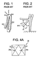
- Fig. 4A is a broken side elevation of an alternative embodiment of an AAA device according to the invention, shown in an expanded state;
- Fig. 5 is a end view of the AAA device according to the invention, shown in an expanded state;
- Fig. 6 is a perspective view of the AAA of the invention shown completely within a delivery catheter;
- Figs. 7 and 8 are perspective views of the AAA of the invention shown partially deployed from a delivery catheter;
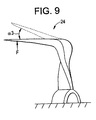
- Fig. 9 is a diagram showing the reaction of the barb of the invention under deformational loading;
- Fig. 10 is a laser pattern for cutting barbs on the stent according to the invention; and
- Figs. 11 and 12 are laser pattern for cutting alternate embodiments of barbs according to the invention.
- Turning now to Figs. 3 through 5, a
vascular endoprosthesis 10 suitable for treatment of an abdominal aortic aneurysm (AAA) includes amain body portion 12 and twosmaller leg portions artificial graft 18 and a self-expandingstent 20 coupled relative to the graft. Thestent 20 is preferably formed from a superelastic, shape memory material such as Nitinol or other nickel-titanium alloy. At an upper end of themain body portion 12, thestruts 21 of thestent 20 defineapexes 22 that are provided withbarbs 24 for coupling the main body portion to the abdominal aortic wall. Referring to Fig. 4A, thebarbs 24a may alternatively or additionally be provided between thestruts 21 at one or more intermediate locations along the length of thestent 20 between its ends. - Referring to Figs. 4 and 5, each
barb 24 includes atwisted neck 26 shape set via shape memory effect metallurgy principals. Several axes can be defined relative to each barb 24: an X-axis extending tangential to the circumference of the stent, a Y-axis extending radially outward from the circumference of the stent, and a Z-axis extending through theneck 26 of thebarb 24. The shape set biases theneck 26 to rotate about the Z-axis and point ananchor portion 28 of the barb radially outward relative to the longitudinal axis A1. of thestent 20 of themain body portion 12 such that the barb extends in alignment with the Y-axis. In a preferred embodiment, eachanchor portion 28, as formed, is also oriented substantially perpendicular (e.g., 90°±15°) relative to the Z-axis, even when in the non-deployed configurations of Figs. 6 and 7. - Referring to Figs. 6 through 8, the motion to move each
barb 22 into a deployed configuration for gripping the abdominal aortic wall is a twisting motion about the Z-axis which twists eachbarb 22 about itsneck 24 into its stress free shape. Such motion moves theanchor portion 28 of eachbarb 22 from being substantially aligned with the circumference of thestent 20 when the stent is in a compressed non-deployed state within the delivery catheter 30 (Fig. 6) to extending radially outwards from the stent when in an expanded deployed state (from Figs. 7 to 8, and eventually to the configuration shown back in Fig. 5). This motion causes the anchor to penetrate the tissue substantially perpendicularly, eliminating any acute tissue migration. It is appreciated that the exact angle of penetration can be designed to optimize migration resistance and downward movement of theendoprosthesis 10 under load of blood flow through thegraft 18. - An important aspect of the invention is that the opening motion of the barb (deployed by the shaped set twist) is decoupled from the strength of the barb, thereby allowing a much stronger barb. Finite element analysis models indicate that designs according to the invention are substantially stronger than conventional designs. In addition, referring to Fig. 9, under a bending load of suitable force F to cause migration if the barb were not sufficiently strong, the stress and strain are distributed over a wider area and have much lower values than in conventional designs and the barb deflects a smaller angular displacement a3 relative to conventional designs (as seen by comparing a3 relative to a2 in Prior Art Fig. 2). While conventional designs have inherent weaknesses to allow the barb to open, it is possible to stiffen and strengthen the barb in the present design, as discussed below, to minimize a3 (to approach zero) without any loss of opening function. Thus, the present design has a relatively an increased resistance to fatigue.
- Beam theory provides that the strength of a beam is primarily affected by its thickness rather than its width. Because the
neck 26 of thebarb 24 is twisted, the width of the neck becomes its thickness in the radial direction, which provides great advantage for design flexibility. For a given wall thickness of starting stent tubing, by changing the width to which the barbs are cut, the stiffness of the barbs are easily changed. - Fig. 10 shows a
laser cut pattern 110 for cutting a series of apexes and barbs on a shape memory alloy tube (or flat which can be bent into a tube) for creating thestent 20 for use in the endoprosthesis according to the invention. The barb angle b can be modified to optimize the anchoring force and the stress/strain distribution. The radius r of the barb can be modified to accommodate more barbs and to change the stiffness of the barbs. As discussed above, the width w of the barbs can be modified to change the stiffness of the barbs and to lower the strain during forming. By way of one example, and not by limitation, the barb angle b can be 103°, the radius r can be 0.38 mm (0.0150 inch) and the width w can be 0.25 mm (0.0100 inch). - The anchors of the barbs may include reverse barbs which increase pullout force. Fig. 11 shows as laser cut pattern for a
reverse barb 212 that is recessed relative to theanchor 28a of thebarb 24a, while Fig. 12 shows laser cut pattern forreverse barbs anchor 28a ofbarb 24b. - There have been described and illustrated herein embodiments of barb design for a stent. While particular embodiments of the invention have been described with reference to an endoluminal prosthesis, particularly suitable for an AAA device, it is not intended that the invention be limited thereto, as it is intended that the invention be as broad in scope as the art will allow and that the specification be read likewise. Thus, the barb design of the invention may be used on stents intended for other purposes. In addition, shape memory alloys, and preferably Nitinol have been disclosed as preferred materials for use in practicing the invention, it will be understood that other shape memory alloys and other shape set materials including biocompatible plastics may be used as well.
Claims (17)
- An endoluminal prosthesis device, comprising:a) a graft that operates as a conduit for blood; andb) a stent coupled to said graft, said stent including at least one barb, each barb including an anchor portion and a twisted neck shape set to bias said anchor portion to rotate about an axis extending in alignment through the neck portion of the barb.
- A device according to claim 1, wherein:each said anchor portion, as formed, is oriented substantially perpendicular relative to the longitudinal axis of said stent.
- A device according to claim 1, wherein:when in a collapsed non-deployed configuration, said anchor portions of said barbs are substantially oriented about a circumference of said stent.
- A device according to claim 1, wherein:when in an expanded deployed configuration, said anchor portions of said barbs are oriented substantially radially relative to the longitudinal axis of said stent.
- A device according to claim 1, wherein:said neck rotates said anchor portions of said barbs into orientation during expansion in said deployed configuration.
- A device according to claim 1, wherein:said graft includes a main body and first and second leg portions coupled relative to said main body portions.
- A device according to claim 1, wherein:said graft is bifurcated.
- A device according to claim 1, wherein:said device is an abdominal aortic aneurism treatment device.
- A stent, comprising:a plurality of struts coupled together to define a tubular stent; andat least one barb coupled to said struts, said barb including an anchor portion and a neck portion shape set to bias said anchor portion to rotate about an axis extending in alignment through the neck portion of the barb.
- A stent according to claim 1 or 9, wherein:said stent and barb together defining three axes, an X-axis extending tangential to a circumference of said stent, a Y-axis extending radially outward from said stent, and a Z-axis extending through said neck portion of said barb,wherein said neck portion is shape set biased to rotate said anchor portion about said Z-axis.
- A stent according to claim 9, wherein:said anchor portion, as formed, is oriented substantially perpendicular relative to said Z-axis.
- A stent according to claim 9, wherein:said stent is movable between a collapsed non-deployed configuration and an expanded deployed configuration, and when said stent is in said non-deployed configuration said anchor portion is substantially oriented about said circumference of said stent.
- A stent according to claim 13, wherein:when said stent is in said deployed configuration, said anchor portion is oriented substantially radially relative to Z-axis.
- A stent according to claim 13, wherein:said neck portion rotates said anchor portion of said barb into orientation during expansion into said deployed configuration.
- A stent according to claim 1 or 9, wherein:said stent is a self-expanding stent.
- A device according to claim 1, wherein:said stent is made of a shape memory alloy, preferably a nickel-titanium alloy.
- An endoluminal prosthesis, comprising:a) a main body including a graft and a stent having a longitudinal axis; andb) first and second leg portions coupled relative to said main body portions,wherein said stent includes at least one barb for coupling the main body portion relative to an abdominal aortic wall, each said barb including an anchor portion and a neck portion shape,
said stent and barb together defining three axes, an X-axis extending tangential to a circumference of said stent, a Y-axis extending radially outward from said stent, and a Z-axis extending through said neck portion of said barb, and
said neck portion is shape set biased to rotate said anchor portion about said Z-axis.
Applications Claiming Priority (1)
| Application Number | Priority Date | Filing Date | Title |
|---|---|---|---|
| US11/488,198 US8298281B2 (en) | 2006-07-18 | 2006-07-18 | Twisted anchoring barb for stent of abdominal aortic aneurysm (AAA) device |
Publications (2)
| Publication Number | Publication Date |
|---|---|
| EP1880693A1 true EP1880693A1 (en) | 2008-01-23 |
| EP1880693B1 EP1880693B1 (en) | 2011-04-13 |
Family
ID=38468528
Family Applications (1)
| Application Number | Title | Priority Date | Filing Date |
|---|---|---|---|
| EP07252732A Active EP1880693B1 (en) | 2006-07-18 | 2007-07-06 | Twisted anchoring barb for stent of abdominal aortic aneurysm (AAA) device |
Country Status (6)
| Country | Link |
|---|---|
| US (4) | US8298281B2 (en) |
| EP (1) | EP1880693B1 (en) |
| JP (1) | JP5340565B2 (en) |
| AT (1) | ATE505159T1 (en) |
| CA (1) | CA2593945C (en) |
| DE (1) | DE602007013841D1 (en) |
Cited By (6)
| Publication number | Priority date | Publication date | Assignee | Title |
|---|---|---|---|---|
| WO2010123665A1 (en) * | 2009-04-24 | 2010-10-28 | Medtronic Vascular, Inc. | Self-flaring active fixation element for a stent graft |
| WO2010147669A1 (en) * | 2009-06-17 | 2010-12-23 | Gore Enterprise Holdings, Inc. | Medical device fixation anchor having improved compaction and delivery properties |
| EP2382945A3 (en) * | 2010-04-29 | 2011-11-23 | Rex Medical, L.P. | Vein filter |
| WO2014025957A1 (en) * | 2012-08-10 | 2014-02-13 | W.L. Gore & Associates, Inc. | Devices and methods for limiting depth of penetration of an anchor within an anatomy |
| US9763766B2 (en) | 2004-01-22 | 2017-09-19 | Argon Medical Devices, Inc. | Vein filter |
| US9814609B2 (en) | 2009-06-17 | 2017-11-14 | W. L. Gore & Associates, Inc. | Medical device fixation anchor suited for balloon expandable stents |
Families Citing this family (32)
| Publication number | Priority date | Publication date | Assignee | Title |
|---|---|---|---|---|
| US20100318181A1 (en) * | 1998-12-11 | 2010-12-16 | Endologix, Inc. | Implantable vascular graft |
| AU2002230661A1 (en) * | 2000-11-15 | 2002-05-27 | Endologix, Inc. | Implantable vascular graft |
| US8211140B2 (en) | 2004-01-22 | 2012-07-03 | Rex Medical, L.P. | Vein filter |
| US7976562B2 (en) | 2004-01-22 | 2011-07-12 | Rex Medical, L.P. | Method of removing a vein filter |
| EP2298318A1 (en) * | 2005-04-04 | 2011-03-23 | Sinexus, Inc. | Device and methods for treating paranasal sinus conditions |
| US8123768B2 (en) * | 2005-10-24 | 2012-02-28 | Gil Vardi | Method and system to restrict stomach size |
| US8070802B2 (en) * | 2007-02-23 | 2011-12-06 | The Trustees Of The University Of Pennsylvania | Mitral valve system |
| US7655037B2 (en) * | 2008-04-17 | 2010-02-02 | Cordis Corporation | Combination barb restraint and stent attachment deployment mechanism |
| US8696739B2 (en) * | 2008-08-29 | 2014-04-15 | Cook Medical Technologies Llc | Barbed anchor |
| US8394139B2 (en) * | 2008-08-29 | 2013-03-12 | Cook Medical Technologies Llc | Barbed anchors for wire stent |
| US8641753B2 (en) * | 2009-01-31 | 2014-02-04 | Cook Medical Technologies Llc | Preform for and an endoluminal prosthesis |
| US8701670B2 (en) * | 2009-04-29 | 2014-04-22 | Bayer Essure Inc. | Trackable occlusion device and catheter system |
| US20140046347A1 (en) * | 2012-08-10 | 2014-02-13 | W. L. Gore & Associates, Inc. | Devices, systems and methods for engaging tissue |
| US9415137B2 (en) | 2012-08-22 | 2016-08-16 | Biomet Manufacturing, Llc. | Directional porous coating |
| US9849006B2 (en) | 2013-03-15 | 2017-12-26 | Children's Medical Center Corporation | Methods and apparatuses for treating vessels |
| JP5960909B2 (en) | 2013-04-01 | 2016-08-02 | テルモ株式会社 | Stent |
| CN105813689B (en) | 2013-11-25 | 2019-06-25 | 定制医学应用有限公司 | Anchoring elements, medical devices including one or more anchoring elements, and related assemblies and methods |
| US10182903B2 (en) | 2014-12-22 | 2019-01-22 | Depuy Mitek, Llc | Whip-stitching with reinforcement material |
| US10130497B2 (en) | 2015-02-20 | 2018-11-20 | Boston Scientific Scimed, Inc. | Stent with retractable anchors |
| WO2017048992A1 (en) | 2015-09-15 | 2017-03-23 | Racz N Sandor | Deployment devices and related assemblies and methods |
| US10420661B2 (en) | 2015-12-17 | 2019-09-24 | Covidien Lp | Stents and stent deployment devices |
| WO2017196909A1 (en) * | 2016-05-12 | 2017-11-16 | St. Jude Medical, Cardiology Division, Inc. | Mitral heart valve replacement |
| US11135050B2 (en) | 2016-10-04 | 2021-10-05 | Boston Scientific Scimed, Inc. | Stent including anchoring members |
| CN110167492B (en) | 2016-11-09 | 2021-10-12 | 波士顿科学国际有限公司 | Stent anchoring system |
| CN110101486B (en) * | 2018-02-01 | 2024-02-27 | 上海微创心通医疗科技有限公司 | Heart valve prosthesis and conveyor thereof |
| WO2019190948A1 (en) | 2018-03-29 | 2019-10-03 | Boston Scientific Scimed, Inc. | Occlusive medical device with fixation members |
| EP3820412B1 (en) | 2018-07-11 | 2024-02-14 | Boston Scientific Scimed, Inc. | Motorized telescoping medical device delivery system with mechanical bailout feature |
| PL3941392T3 (en) | 2019-03-20 | 2025-08-25 | inQB8 Medical Technologies, LLC | Aortic dissection implant |
| US12427018B2 (en) * | 2020-05-11 | 2025-09-30 | St. Jude Medical, Cardiology Division, Inc. | Transcatheter mitral valve fixation concepts |
| KR20230073286A (en) * | 2020-09-22 | 2023-05-25 | 엔도론 메디컬 엘티디. | tissue fixation device |
| CA3195219A1 (en) * | 2020-09-29 | 2022-04-07 | Boston Scientific Scimed, Inc. | Stent with anti-migration features |
| US12558100B2 (en) | 2023-06-02 | 2026-02-24 | Endoron Medical Ltd. | Intravascular device for anchoring a graft to tissue |
Citations (4)
| Publication number | Priority date | Publication date | Assignee | Title |
|---|---|---|---|---|
| EP0712614A1 (en) * | 1994-11-15 | 1996-05-22 | Advanced Cardiovascular Systems, Inc. | Intraluminal stent for attaching a graft |
| WO2002100297A2 (en) | 2001-06-08 | 2002-12-19 | Rex Medical, L.P. | Vascular device with valve for approximating vessel wall |
| US20030220683A1 (en) * | 2002-05-22 | 2003-11-27 | Zarouhi Minasian | Endoluminal device having barb assembly and method of using same |
| WO2004006983A2 (en) * | 2002-07-11 | 2004-01-22 | University Of Virginia Patent Foundation | Expandable body having deployable microstructures and related methods |
Family Cites Families (21)
| Publication number | Priority date | Publication date | Assignee | Title |
|---|---|---|---|---|
| US5720776A (en) * | 1991-10-25 | 1998-02-24 | Cook Incorporated | Barb and expandable transluminal graft prosthesis for repair of aneurysm |
| US5843167A (en) * | 1993-04-22 | 1998-12-01 | C. R. Bard, Inc. | Method and apparatus for recapture of hooked endoprosthesis |
| EP0657147B1 (en) * | 1993-11-04 | 1999-08-04 | C.R. Bard, Inc. | Non-migrating vascular prosthesis |
| AU708360B2 (en) | 1994-09-15 | 1999-08-05 | C.R. Bard Inc. | Hooked endoprosthesis |
| US6814748B1 (en) * | 1995-06-07 | 2004-11-09 | Endovascular Technologies, Inc. | Intraluminal grafting system |
| US5976178A (en) * | 1996-11-07 | 1999-11-02 | Vascular Science Inc. | Medical grafting methods |
| US6036702A (en) * | 1997-04-23 | 2000-03-14 | Vascular Science Inc. | Medical grafting connectors and fasteners |
| US6120432A (en) * | 1997-04-23 | 2000-09-19 | Vascular Science Inc. | Medical grafting methods and apparatus |
| US5860998A (en) * | 1996-11-25 | 1999-01-19 | C. R. Bard, Inc. | Deployment device for tubular expandable prosthesis |
| US6517573B1 (en) * | 2000-04-11 | 2003-02-11 | Endovascular Technologies, Inc. | Hook for attaching to a corporeal lumen and method of manufacturing |
| US6695878B2 (en) | 2000-06-26 | 2004-02-24 | Rex Medical, L.P. | Vascular device for valve leaflet apposition |
| WO2002010297A2 (en) | 2000-08-02 | 2002-02-07 | Eastman Chemical Company | Stable aqueous polymer dispersions and formulations with latex polymers to form waterborne coatings |
| US6736133B2 (en) * | 2002-04-09 | 2004-05-18 | Hon Technology Inc. | Air filtration and sterilization system for a fireplace |
| US20040117004A1 (en) * | 2002-05-16 | 2004-06-17 | Osborne Thomas A. | Stent and method of forming a stent with integral barbs |
| US7828839B2 (en) * | 2002-05-16 | 2010-11-09 | Cook Incorporated | Flexible barb for anchoring a prosthesis |
| US9060844B2 (en) * | 2002-11-01 | 2015-06-23 | Valentx, Inc. | Apparatus and methods for treatment of morbid obesity |
| US7404824B1 (en) * | 2002-11-15 | 2008-07-29 | Advanced Cardiovascular Systems, Inc. | Valve aptation assist device |
| US7704266B2 (en) * | 2004-01-22 | 2010-04-27 | Rex Medical, L.P. | Vein filter |
| JP4651625B2 (en) * | 2004-01-27 | 2011-03-16 | メッド・インスティテュート・インコーポレイテッド | Fixed barbs for attachment to medical prostheses |
| DK1737384T3 (en) * | 2004-04-16 | 2010-03-08 | Cook Inc | Removable vena cava filter with inwardly directed anchoring hooks in collapsed condition |
| US7905915B2 (en) * | 2007-12-27 | 2011-03-15 | Cook Incorporated | Z-stent with incorporated barbs |
-
2006
- 2006-07-18 US US11/488,198 patent/US8298281B2/en not_active Expired - Fee Related
-
2007
- 2007-07-06 DE DE602007013841T patent/DE602007013841D1/en active Active
- 2007-07-06 EP EP07252732A patent/EP1880693B1/en active Active
- 2007-07-06 AT AT07252732T patent/ATE505159T1/en not_active IP Right Cessation
- 2007-07-17 JP JP2007186016A patent/JP5340565B2/en active Active
- 2007-07-17 CA CA2593945A patent/CA2593945C/en active Active
-
2010
- 2010-08-19 US US12/859,433 patent/US8372143B2/en active Active
- 2010-08-19 US US12/859,382 patent/US8372141B2/en active Active
- 2010-08-19 US US12/859,412 patent/US8372142B2/en active Active
Patent Citations (4)
| Publication number | Priority date | Publication date | Assignee | Title |
|---|---|---|---|---|
| EP0712614A1 (en) * | 1994-11-15 | 1996-05-22 | Advanced Cardiovascular Systems, Inc. | Intraluminal stent for attaching a graft |
| WO2002100297A2 (en) | 2001-06-08 | 2002-12-19 | Rex Medical, L.P. | Vascular device with valve for approximating vessel wall |
| US20030220683A1 (en) * | 2002-05-22 | 2003-11-27 | Zarouhi Minasian | Endoluminal device having barb assembly and method of using same |
| WO2004006983A2 (en) * | 2002-07-11 | 2004-01-22 | University Of Virginia Patent Foundation | Expandable body having deployable microstructures and related methods |
Cited By (15)
| Publication number | Priority date | Publication date | Assignee | Title |
|---|---|---|---|---|
| US10639139B2 (en) | 2004-01-22 | 2020-05-05 | Argon Medical Devices, Inc. | Vein filter |
| US9763766B2 (en) | 2004-01-22 | 2017-09-19 | Argon Medical Devices, Inc. | Vein filter |
| WO2010123665A1 (en) * | 2009-04-24 | 2010-10-28 | Medtronic Vascular, Inc. | Self-flaring active fixation element for a stent graft |
| US8876883B2 (en) | 2009-04-24 | 2014-11-04 | Medtronic Vascular, Inc. | Self-flaring active fixation element for a stent graft |
| RU2516555C2 (en) * | 2009-06-17 | 2014-05-20 | Гор Энтерпрайз Холдингс, Инк. | Fixator of medical device with improved compression and delivery characteristics |
| AU2010260459B2 (en) * | 2009-06-17 | 2013-11-07 | W. L. Gore & Associates, Inc. | Medical device fixation anchor having improved compaction and delivery properties |
| CN102458313A (en) * | 2009-06-17 | 2012-05-16 | 戈尔企业控股股份有限公司 | Medical device anchors with improved retraction and delivery properties |
| US9808361B2 (en) | 2009-06-17 | 2017-11-07 | W. L. Gore & Associates, Inc. | Medical device fixation anchor having improved compaction and delivery |
| US9814609B2 (en) | 2009-06-17 | 2017-11-14 | W. L. Gore & Associates, Inc. | Medical device fixation anchor suited for balloon expandable stents |
| US10492934B2 (en) | 2009-06-17 | 2019-12-03 | W. L. Gore & Associates, Inc. | Medical device fixation anchor having improved compaction and delivery |
| WO2010147669A1 (en) * | 2009-06-17 | 2010-12-23 | Gore Enterprise Holdings, Inc. | Medical device fixation anchor having improved compaction and delivery properties |
| US11202717B2 (en) | 2009-06-17 | 2021-12-21 | W. L. Gore & Associates, Inc. | Medical device fixation anchor having improved compaction and delivery |
| EP2382945A3 (en) * | 2010-04-29 | 2011-11-23 | Rex Medical, L.P. | Vein filter |
| WO2014025957A1 (en) * | 2012-08-10 | 2014-02-13 | W.L. Gore & Associates, Inc. | Devices and methods for limiting depth of penetration of an anchor within an anatomy |
| US11458007B2 (en) | 2012-08-10 | 2022-10-04 | W. L. Gore & Associates, Inc. | Devices and methods for limiting a depth of penetration for an anchor within an anatomy |
Also Published As
| Publication number | Publication date |
|---|---|
| JP5340565B2 (en) | 2013-11-13 |
| US20080021544A1 (en) | 2008-01-24 |
| US20100312323A1 (en) | 2010-12-09 |
| EP1880693B1 (en) | 2011-04-13 |
| US8372141B2 (en) | 2013-02-12 |
| CA2593945A1 (en) | 2008-01-18 |
| DE602007013841D1 (en) | 2011-05-26 |
| CA2593945C (en) | 2013-12-17 |
| ATE505159T1 (en) | 2011-04-15 |
| US8372143B2 (en) | 2013-02-12 |
| US8298281B2 (en) | 2012-10-30 |
| JP2008029839A (en) | 2008-02-14 |
| US8372142B2 (en) | 2013-02-12 |
| US20100312330A1 (en) | 2010-12-09 |
| US20100318177A1 (en) | 2010-12-16 |
Similar Documents
| Publication | Publication Date | Title |
|---|---|---|
| EP1880693B1 (en) | Twisted anchoring barb for stent of abdominal aortic aneurysm (AAA) device | |
| EP2030592B1 (en) | Stent graft sealing zone connecting structure | |
| EP1621160B1 (en) | Low deployment force delivery device | |
| EP1878392B1 (en) | AAA repair device with aneurysm sac access port | |
| EP1771128B1 (en) | Reduced profile aaa device | |
| EP1771129B1 (en) | Aaa device having connected bifurcated legs | |
| EP2548532B1 (en) | Stent-graft or graft with durability or stiffness enhancing elements | |
| CA2944014C (en) | Method and device for attaching a stent structure to aaa graft material | |
| US7344562B2 (en) | AAA low profile support structure | |
| EP1621159A1 (en) | Abdominal aortic aneurism (AAA) low profile support structure |
Legal Events
| Date | Code | Title | Description |
|---|---|---|---|
| PUAI | Public reference made under article 153(3) epc to a published international application that has entered the european phase |
Free format text: ORIGINAL CODE: 0009012 |
|
| AK | Designated contracting states |
Kind code of ref document: A1 Designated state(s): AT BE BG CH CY CZ DE DK EE ES FI FR GB GR HU IE IS IT LI LT LU LV MC MT NL PL PT RO SE SI SK TR |
|
| AX | Request for extension of the european patent |
Extension state: AL BA HR MK YU |
|
| 17P | Request for examination filed |
Effective date: 20080624 |
|
| 17Q | First examination report despatched |
Effective date: 20080811 |
|
| AKX | Designation fees paid |
Designated state(s): AT BE BG CH CY CZ DE DK EE ES FI FR GB GR HU IE IS IT LI LT LU LV MC MT NL PL PT RO SE SI SK TR |
|
| GRAP | Despatch of communication of intention to grant a patent |
Free format text: ORIGINAL CODE: EPIDOSNIGR1 |
|
| RIC1 | Information provided on ipc code assigned before grant |
Ipc: A61F 2/90 20060101AFI20101130BHEP Ipc: A61F 2/06 20060101ALI20101130BHEP |
|
| GRAS | Grant fee paid |
Free format text: ORIGINAL CODE: EPIDOSNIGR3 |
|
| GRAA | (expected) grant |
Free format text: ORIGINAL CODE: 0009210 |
|
| AK | Designated contracting states |
Kind code of ref document: B1 Designated state(s): AT BE BG CH CY CZ DE DK EE ES FI FR GB GR HU IE IS IT LI LT LU LV MC MT NL PL PT RO SE SI SK TR |
|
| REG | Reference to a national code |
Ref country code: GB Ref legal event code: FG4D |
|
| REG | Reference to a national code |
Ref country code: CH Ref legal event code: EP |
|
| REG | Reference to a national code |
Ref country code: IE Ref legal event code: FG4D |
|
| REF | Corresponds to: |
Ref document number: 602007013841 Country of ref document: DE Date of ref document: 20110526 Kind code of ref document: P |
|
| REG | Reference to a national code |
Ref country code: DE Ref legal event code: R096 Ref document number: 602007013841 Country of ref document: DE Effective date: 20110526 |
|
| REG | Reference to a national code |
Ref country code: NL Ref legal event code: T3 |
|
| LTIE | Lt: invalidation of european patent or patent extension |
Effective date: 20110413 |
|
| PG25 | Lapsed in a contracting state [announced via postgrant information from national office to epo] |
Ref country code: PT Free format text: LAPSE BECAUSE OF FAILURE TO SUBMIT A TRANSLATION OF THE DESCRIPTION OR TO PAY THE FEE WITHIN THE PRESCRIBED TIME-LIMIT Effective date: 20110816 Ref country code: SE Free format text: LAPSE BECAUSE OF FAILURE TO SUBMIT A TRANSLATION OF THE DESCRIPTION OR TO PAY THE FEE WITHIN THE PRESCRIBED TIME-LIMIT Effective date: 20110413 Ref country code: LT Free format text: LAPSE BECAUSE OF FAILURE TO SUBMIT A TRANSLATION OF THE DESCRIPTION OR TO PAY THE FEE WITHIN THE PRESCRIBED TIME-LIMIT Effective date: 20110413 |
|
| PG25 | Lapsed in a contracting state [announced via postgrant information from national office to epo] |
Ref country code: GR Free format text: LAPSE BECAUSE OF FAILURE TO SUBMIT A TRANSLATION OF THE DESCRIPTION OR TO PAY THE FEE WITHIN THE PRESCRIBED TIME-LIMIT Effective date: 20110714 Ref country code: BE Free format text: LAPSE BECAUSE OF FAILURE TO SUBMIT A TRANSLATION OF THE DESCRIPTION OR TO PAY THE FEE WITHIN THE PRESCRIBED TIME-LIMIT Effective date: 20110413 Ref country code: IS Free format text: LAPSE BECAUSE OF FAILURE TO SUBMIT A TRANSLATION OF THE DESCRIPTION OR TO PAY THE FEE WITHIN THE PRESCRIBED TIME-LIMIT Effective date: 20110813 Ref country code: FI Free format text: LAPSE BECAUSE OF FAILURE TO SUBMIT A TRANSLATION OF THE DESCRIPTION OR TO PAY THE FEE WITHIN THE PRESCRIBED TIME-LIMIT Effective date: 20110413 Ref country code: SI Free format text: LAPSE BECAUSE OF FAILURE TO SUBMIT A TRANSLATION OF THE DESCRIPTION OR TO PAY THE FEE WITHIN THE PRESCRIBED TIME-LIMIT Effective date: 20110413 Ref country code: AT Free format text: LAPSE BECAUSE OF FAILURE TO SUBMIT A TRANSLATION OF THE DESCRIPTION OR TO PAY THE FEE WITHIN THE PRESCRIBED TIME-LIMIT Effective date: 20110413 Ref country code: LV Free format text: LAPSE BECAUSE OF FAILURE TO SUBMIT A TRANSLATION OF THE DESCRIPTION OR TO PAY THE FEE WITHIN THE PRESCRIBED TIME-LIMIT Effective date: 20110413 Ref country code: CY Free format text: LAPSE BECAUSE OF FAILURE TO SUBMIT A TRANSLATION OF THE DESCRIPTION OR TO PAY THE FEE WITHIN THE PRESCRIBED TIME-LIMIT Effective date: 20110413 Ref country code: ES Free format text: LAPSE BECAUSE OF FAILURE TO SUBMIT A TRANSLATION OF THE DESCRIPTION OR TO PAY THE FEE WITHIN THE PRESCRIBED TIME-LIMIT Effective date: 20110724 |
|
| PG25 | Lapsed in a contracting state [announced via postgrant information from national office to epo] |
Ref country code: MT Free format text: LAPSE BECAUSE OF FAILURE TO SUBMIT A TRANSLATION OF THE DESCRIPTION OR TO PAY THE FEE WITHIN THE PRESCRIBED TIME-LIMIT Effective date: 20110413 |
|
| PG25 | Lapsed in a contracting state [announced via postgrant information from national office to epo] |
Ref country code: CZ Free format text: LAPSE BECAUSE OF FAILURE TO SUBMIT A TRANSLATION OF THE DESCRIPTION OR TO PAY THE FEE WITHIN THE PRESCRIBED TIME-LIMIT Effective date: 20110413 Ref country code: EE Free format text: LAPSE BECAUSE OF FAILURE TO SUBMIT A TRANSLATION OF THE DESCRIPTION OR TO PAY THE FEE WITHIN THE PRESCRIBED TIME-LIMIT Effective date: 20110413 |
|
| PLBE | No opposition filed within time limit |
Free format text: ORIGINAL CODE: 0009261 |
|
| STAA | Information on the status of an ep patent application or granted ep patent |
Free format text: STATUS: NO OPPOSITION FILED WITHIN TIME LIMIT |
|
| PG25 | Lapsed in a contracting state [announced via postgrant information from national office to epo] |
Ref country code: DK Free format text: LAPSE BECAUSE OF FAILURE TO SUBMIT A TRANSLATION OF THE DESCRIPTION OR TO PAY THE FEE WITHIN THE PRESCRIBED TIME-LIMIT Effective date: 20110413 Ref country code: MC Free format text: LAPSE BECAUSE OF NON-PAYMENT OF DUE FEES Effective date: 20110731 Ref country code: SK Free format text: LAPSE BECAUSE OF FAILURE TO SUBMIT A TRANSLATION OF THE DESCRIPTION OR TO PAY THE FEE WITHIN THE PRESCRIBED TIME-LIMIT Effective date: 20110413 Ref country code: RO Free format text: LAPSE BECAUSE OF FAILURE TO SUBMIT A TRANSLATION OF THE DESCRIPTION OR TO PAY THE FEE WITHIN THE PRESCRIBED TIME-LIMIT Effective date: 20110413 Ref country code: PL Free format text: LAPSE BECAUSE OF FAILURE TO SUBMIT A TRANSLATION OF THE DESCRIPTION OR TO PAY THE FEE WITHIN THE PRESCRIBED TIME-LIMIT Effective date: 20110413 |
|
| REG | Reference to a national code |
Ref country code: CH Ref legal event code: PL |
|
| 26N | No opposition filed |
Effective date: 20120116 |
|
| PG25 | Lapsed in a contracting state [announced via postgrant information from national office to epo] |
Ref country code: LI Free format text: LAPSE BECAUSE OF NON-PAYMENT OF DUE FEES Effective date: 20110731 Ref country code: CH Free format text: LAPSE BECAUSE OF NON-PAYMENT OF DUE FEES Effective date: 20110731 |
|
| REG | Reference to a national code |
Ref country code: DE Ref legal event code: R097 Ref document number: 602007013841 Country of ref document: DE Effective date: 20120116 |
|
| PG25 | Lapsed in a contracting state [announced via postgrant information from national office to epo] |
Ref country code: LU Free format text: LAPSE BECAUSE OF NON-PAYMENT OF DUE FEES Effective date: 20110706 |
|
| PG25 | Lapsed in a contracting state [announced via postgrant information from national office to epo] |
Ref country code: BG Free format text: LAPSE BECAUSE OF FAILURE TO SUBMIT A TRANSLATION OF THE DESCRIPTION OR TO PAY THE FEE WITHIN THE PRESCRIBED TIME-LIMIT Effective date: 20110713 |
|
| PG25 | Lapsed in a contracting state [announced via postgrant information from national office to epo] |
Ref country code: TR Free format text: LAPSE BECAUSE OF FAILURE TO SUBMIT A TRANSLATION OF THE DESCRIPTION OR TO PAY THE FEE WITHIN THE PRESCRIBED TIME-LIMIT Effective date: 20110413 |
|
| PG25 | Lapsed in a contracting state [announced via postgrant information from national office to epo] |
Ref country code: HU Free format text: LAPSE BECAUSE OF FAILURE TO SUBMIT A TRANSLATION OF THE DESCRIPTION OR TO PAY THE FEE WITHIN THE PRESCRIBED TIME-LIMIT Effective date: 20110413 |
|
| REG | Reference to a national code |
Ref country code: FR Ref legal event code: PLFP Year of fee payment: 10 |
|
| REG | Reference to a national code |
Ref country code: FR Ref legal event code: PLFP Year of fee payment: 11 |
|
| REG | Reference to a national code |
Ref country code: GB Ref legal event code: 732E Free format text: REGISTERED BETWEEN 20180614 AND 20180620 |
|
| REG | Reference to a national code |
Ref country code: FR Ref legal event code: PLFP Year of fee payment: 12 |
|
| REG | Reference to a national code |
Ref country code: DE Ref legal event code: R082 Ref document number: 602007013841 Country of ref document: DE Representative=s name: PROCK, THOMAS, DR., GB |
|
| REG | Reference to a national code |
Ref country code: NL Ref legal event code: PD Owner name: CARDINAL HEALTH SWITZERLAND 515 GMBH; CH Free format text: DETAILS ASSIGNMENT: CHANGE OF OWNER(S), ASSIGNMENT; FORMER OWNER NAME: CORDIS CORPORATION Effective date: 20200708 |
|
| REG | Reference to a national code |
Ref country code: GB Ref legal event code: 732E Free format text: REGISTERED BETWEEN 20201126 AND 20201202 |
|
| REG | Reference to a national code |
Ref country code: DE Ref legal event code: R082 Ref document number: 602007013841 Country of ref document: DE Representative=s name: PROCK, THOMAS, DR., GB Ref country code: DE Ref legal event code: R081 Ref document number: 602007013841 Country of ref document: DE Owner name: CARDINAL HEALTH SWITZERLAND 515 GMBH, CH Free format text: FORMER OWNER: CORDIS CORP., MIAMI LAKES, FLA., US |
|
| PGFP | Annual fee paid to national office [announced via postgrant information from national office to epo] |
Ref country code: NL Payment date: 20240726 Year of fee payment: 18 |
|
| PGFP | Annual fee paid to national office [announced via postgrant information from national office to epo] |
Ref country code: DE Payment date: 20240729 Year of fee payment: 18 Ref country code: IE Payment date: 20240729 Year of fee payment: 18 |
|
| PGFP | Annual fee paid to national office [announced via postgrant information from national office to epo] |
Ref country code: GB Payment date: 20240729 Year of fee payment: 18 |
|
| PGFP | Annual fee paid to national office [announced via postgrant information from national office to epo] |
Ref country code: FR Payment date: 20240725 Year of fee payment: 18 |
|
| PGFP | Annual fee paid to national office [announced via postgrant information from national office to epo] |
Ref country code: IT Payment date: 20240719 Year of fee payment: 18 |
|
| REG | Reference to a national code |
Ref country code: DE Ref legal event code: R119 Ref document number: 602007013841 Country of ref document: DE |
|
| REG | Reference to a national code |
Ref country code: NL Ref legal event code: MM Effective date: 20250801 |
|
| GBPC | Gb: european patent ceased through non-payment of renewal fee |
Effective date: 20250706 |
|
| PG25 | Lapsed in a contracting state [announced via postgrant information from national office to epo] |
Ref country code: GB Free format text: LAPSE BECAUSE OF NON-PAYMENT OF DUE FEES Effective date: 20250706 |
|
| PG25 | Lapsed in a contracting state [announced via postgrant information from national office to epo] |
Ref country code: DE Free format text: LAPSE BECAUSE OF NON-PAYMENT OF DUE FEES Effective date: 20260203 |
|
| PG25 | Lapsed in a contracting state [announced via postgrant information from national office to epo] |
Ref country code: NL Free format text: LAPSE BECAUSE OF NON-PAYMENT OF DUE FEES Effective date: 20250801 |
|
| PG25 | Lapsed in a contracting state [announced via postgrant information from national office to epo] |
Ref country code: FR Free format text: LAPSE BECAUSE OF NON-PAYMENT OF DUE FEES Effective date: 20250731 |