EP1879275A1 - Distribution switchgear - Google Patents
Distribution switchgear Download PDFInfo
- Publication number
- EP1879275A1 EP1879275A1 EP07012820A EP07012820A EP1879275A1 EP 1879275 A1 EP1879275 A1 EP 1879275A1 EP 07012820 A EP07012820 A EP 07012820A EP 07012820 A EP07012820 A EP 07012820A EP 1879275 A1 EP1879275 A1 EP 1879275A1
- Authority
- EP
- European Patent Office
- Prior art keywords
- busbar
- solid
- circuit breaker
- insulated
- equipment
- Prior art date
- Legal status (The legal status is an assumption and is not a legal conclusion. Google has not performed a legal analysis and makes no representation as to the accuracy of the status listed.)
- Granted
Links
- 238000000819 phase cycle Methods 0.000 claims abstract description 26
- 238000000638 solvent extraction Methods 0.000 claims abstract description 7
- 238000007789 sealing Methods 0.000 claims description 7
- 230000001012 protector Effects 0.000 claims description 5
- 230000001050 lubricating effect Effects 0.000 claims description 4
- 239000007787 solid Substances 0.000 claims description 4
- 230000001681 protective effect Effects 0.000 claims description 3
- 238000012423 maintenance Methods 0.000 description 11
- 238000005192 partition Methods 0.000 description 10
- 238000010586 diagram Methods 0.000 description 9
- 230000000694 effects Effects 0.000 description 4
- 238000009434 installation Methods 0.000 description 4
- 238000009413 insulation Methods 0.000 description 4
- 239000006096 absorbing agent Substances 0.000 description 3
- 230000005494 condensation Effects 0.000 description 2
- 238000009833 condensation Methods 0.000 description 2
- 238000010276 construction Methods 0.000 description 2
- 239000000428 dust Substances 0.000 description 2
- 239000012212 insulator Substances 0.000 description 2
- 230000002265 prevention Effects 0.000 description 2
- 238000010926 purge Methods 0.000 description 2
- 230000009466 transformation Effects 0.000 description 2
- 238000004140 cleaning Methods 0.000 description 1
- 229920001971 elastomer Polymers 0.000 description 1
- 230000007613 environmental effect Effects 0.000 description 1
- 239000003822 epoxy resin Substances 0.000 description 1
- 239000000463 material Substances 0.000 description 1
- 229920000647 polyepoxide Polymers 0.000 description 1
- 150000003839 salts Chemical class 0.000 description 1
- 229920002379 silicone rubber Polymers 0.000 description 1
Images






Classifications
-
- H—ELECTRICITY
- H02—GENERATION; CONVERSION OR DISTRIBUTION OF ELECTRIC POWER
- H02B—BOARDS, SUBSTATIONS OR SWITCHING ARRANGEMENTS FOR THE SUPPLY OR DISTRIBUTION OF ELECTRIC POWER
- H02B1/00—Frameworks, boards, panels, desks, casings; Details of substations or switching arrangements
- H02B1/015—Boards, panels, desks; Parts thereof or accessories therefor
- H02B1/03—Boards, panels, desks; Parts thereof or accessories therefor for energy meters
-
- H—ELECTRICITY
- H02—GENERATION; CONVERSION OR DISTRIBUTION OF ELECTRIC POWER
- H02B—BOARDS, SUBSTATIONS OR SWITCHING ARRANGEMENTS FOR THE SUPPLY OR DISTRIBUTION OF ELECTRIC POWER
- H02B13/00—Arrangement of switchgear in which switches are enclosed in, or structurally associated with, a casing, e.g. cubicle
- H02B13/01—Arrangement of switchgear in which switches are enclosed in, or structurally associated with, a casing, e.g. cubicle with resin casing
-
- H—ELECTRICITY
- H02—GENERATION; CONVERSION OR DISTRIBUTION OF ELECTRIC POWER
- H02B—BOARDS, SUBSTATIONS OR SWITCHING ARRANGEMENTS FOR THE SUPPLY OR DISTRIBUTION OF ELECTRIC POWER
- H02B1/00—Frameworks, boards, panels, desks, casings; Details of substations or switching arrangements
- H02B1/20—Bus-bar or other wiring layouts, e.g. in cubicles, in switchyards
-
- H—ELECTRICITY
- H02—GENERATION; CONVERSION OR DISTRIBUTION OF ELECTRIC POWER
- H02B—BOARDS, SUBSTATIONS OR SWITCHING ARRANGEMENTS FOR THE SUPPLY OR DISTRIBUTION OF ELECTRIC POWER
- H02B11/00—Switchgear having carriage withdrawable for isolation
- H02B11/02—Details
-
- H—ELECTRICITY
- H02—GENERATION; CONVERSION OR DISTRIBUTION OF ELECTRIC POWER
- H02B—BOARDS, SUBSTATIONS OR SWITCHING ARRANGEMENTS FOR THE SUPPLY OR DISTRIBUTION OF ELECTRIC POWER
- H02B13/00—Arrangement of switchgear in which switches are enclosed in, or structurally associated with, a casing, e.g. cubicle
- H02B13/02—Arrangement of switchgear in which switches are enclosed in, or structurally associated with, a casing, e.g. cubicle with metal casing
- H02B13/025—Safety arrangements, e.g. in case of excessive pressure or fire due to electrical defect
Definitions
- the present invention relates to distribution switchgear, and more particularly to distribution switchgear in which a circuit breaker, a current transformer, a zero-phase-sequence current transformer and so on are disposed in series.
- distribution switchgear is a unit comprised of a circuit breaker, a current transformer (CT) and a zero-phase-sequence current transformer which are connected in series, where the unit moves on a rail or the unit placed on a carriage is housed in a power distribution panel in a way that it can be drawn out from the power distribution panel (for example, see Patent Documents 1 and 2).
- the conventional distribution switchgear Since the conventional distribution switchgear is compact and features good maintainability as a unit constituting distribution switchgear, it has been used in various systems. It has been found from its use in various systems that the distribution switchgear has to be improved in several points.
- the first point to be improved is as follows: in the conventional distribution switchgear, although a zero-phase-sequence current transformer is located on the load side of the circuit breaker to detect a ground fault on the load side of the circuit breaker, there is no means for ground fault protection of the whole load side including a circuit breaker located on the power supply side of the zero-phase-sequence current transformer.
- the present invention has been made based on the above circumstances and its object is to provide a distribution switchgear which not only protects the whole load side including a circuit breaker against ground faults to widen the protection range and thus increases reliability but also can achieve labor saving in maintenance and a longer service life.
- an equipment room 4 and a main busbar room 5 are formed in a distribution panel housing 1 on its front side and on its back side respectively by partitioning; in the equipment room 4, equipment units 14, each comprised of a vacuum circuit breaker 10, a current transformer 11 on the load side of the vacuum circuit breaker 10 and a zero-phase-sequence current transformer 12 on the power supply side of the vacuum circuit breaker 10, are vertically disposed; and in the main busbar room 5, a solid-insulated main busbar 20 disposed along the housing 1's width direction, a solid-insulated link busbar 21 connected with the main busbar and connected with one side of each of the equipment units 14 and solid-insulated branch busbars 29, 30 connected with the other side of the equipment units 14 are disposed.
- distribution switchgear is characterized in that an equipment room and a main busbar room are formed in a distribution panel housing on its front side and on its back side respectively by partitioning; in the equipment room, equipment units, each comprised of a circuit breaker, a current transformer on a load side of the circuit breaker and a zero-phase-sequence current transformer on a power supply side of the circuit breaker, are vertically disposed; and in the main busbar room, a solid-insulated main busbar disposed along the housing's width direction, a solid-insulated link busbar connected with the main busbar and connected with one side of each of the equipment units and a solid-insulated branch busbar connected with the other side of each of the equipment unit are disposed, or characterized by comprising an array of panels disposed side by side in a housing which are a first panel in which two equipment units each comprised of a circuit breaker, a current transformer on a load side of the circuit breaker and a zero-phase-se
- An equipment room 4 and a main busbar room 5 are formed in a distribution panel housing 1 on its front side and on its back side respectively by partitioning; in the equipment room 4, equipment units 14 , each comprised of a vacuum circuit breaker 10, a current transformer 11 on the load side of the vacuum circuit breaker 10 and a zero-phase-sequence current transformer 12 on the power supply side of the vacuum circuit breaker 10, are vertically disposed; and in the main busbar room 5, a solid-insulated main busbar 20 disposed along the housing 1's width direction, a solid-insulated link busbar 21 connected with the main busbar and connected with one side of each of the equipment units 14 and solid-insulated branch busbars 29, 30 connected with the other side of the equipment units 14 are disposed.
- a zero-phase-sequence current transformer is located on the power supply side of a circuit breaker constituting an equipment unit, the whole load side including the circuit breaker can be protected against ground faults to widen the protection range and thereby increase reliability, and also since a solid-insulated main busbar is housed in a main busbar room separate from an equipment room housing equipment units, labor saving in maintenance and longer service life can be achieved.
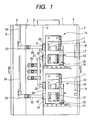
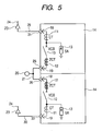
- Figs. 1 to 5 show distribution switchgear according to a first embodiment of the present invention, in which Fig. 1 is a longitudinal sectional view of distribution switchgear according to an embodiment of the invention, Fig. 2 is a front view of it, Fig. 3 is a partially sectional perspective view of the distribution switchgear shown in Fig.1 according to an embodiment of the invention, Fig. 4 is an enlarged perspective view showing a main busbar of the distribution switchgear shown in Fig. 1 according to an embodiment of the invention, and Fig. 5 is a general connection diagram of distribution switchgear according to an embodiment of the invention.
- a front door 7 is provided on the front of the housing 1 in an openable/closable manner.
- a digital protective control unit 8 is mounted on the door 7.
- a back door 9 is provided on the back of the housing 1 in an openable/closable manner as shown in Fig. 1.
- equipment units 14 are disposed vertically, where they are comprised of vacuum circuit breakers (VCB) 10 arranged side by side along the width direction of the housing 1 (orthogonal to the paper surface of Fig.1), current transformers (CT) 11 provided respectively on the load side of the vacuum circuit breakers 10, zero-phase-sequence current transformers (ZCT) 12 provided respectively on the power supply side of the vacuum circuit breakers 10, and surge absorbers (SA) 13 for protection against external lightning surge (see Fig. 5).
- VVB vacuum circuit breakers
- CT current transformers
- ZCT zero-phase-sequence current transformers
- SA surge absorbers
- These equipment units 14 can be drawn out toward the front of the housing 1 (right in Fig. 1) by means of carriages 15 at their bottom and guides 16 which guide the carriages 15.
- These equipment units 14 are usually fixed by lock devices (not shown) and when drawing them frontward, they can be drawn frontward by unlocking the lock devices (not shown) and pulling handles 17 on the front of the equipment units 14. This means that in the worst case, the equipment can be replaced easily with minimized replacement time.
- the vacuum circuit breaker 10, current transformer 11, and zero-phase-sequence current transformer 12 which constitute an equipment unit 14 as mentioned above are connected in series as shown in Fig. 5.
- the zero-phase-sequence current transformer 12 is located on the power supply side of the vacuum circuit breaker 10 and the current transformer 11 is located on the load side of the vacuum circuit breaker 10 and the surge absorber 13 for protection against external lightning surge is connected on the load side of the vacuum circuit breaker 10.
- the current transformer is of the multi current ratio type which can cope with plural rated currents, contributing to increased reliability.
- the opening/closing mechanism of the above vacuum circuit breaker 10 is an electromagnetic operating device which combines an electromagnet and a permanent magnet and uses a solid lubricating bearing in the sliding part of the mechanism, permitting easy greaseless maintenance.
- a terminal 18 connected with the fixed electrode side of a vacuum circuit breaker 10 and a terminal 19 connected with the movable electrode side of the vacuum circuit breaker are disposed in the back of each equipment unit 14 ; more particularly in each of the upper and lower equipment units 14 , the terminal 18 is in an upper position and the terminal 19 is below it.
- These terminals 18, 19 are connected with a link busbar 21 connected with the main busbar 20 in the main busbar room 5 (stated later), and branch busbars 29, 30 through air bushing in a connectable/disconnectable manner.
- reference numeral 23 represents a cable sealing end and reference numeral 24 represents a cable.
- the solid-insulated main busbar 20 is disposed midway in the height direction of the housing 1 along the width direction of the housing 1 in the main busbar room 5.
- One end of the solid-insulated link busbar 21 is connected with the main busbar 20.
- the other end of the link busbar 21 is bifurcated and one connecting terminal 25 of it is led into the equipment room 4 in a way that it can be connected to, or disconnected from, the above upper equipment unit 14, and the other terminal 26 is led into the equipment room 4 in a way that it can be connected to, or disconnected from, the above lower equipment unit 14.
- These connecting terminals 25, 26 are fixed on the partition plate 2 through air disconnection bushings 27, 28, respectively.
- the solid-insulated branch busbars 29, 30 are disposed in the upper and lower portions of the main busbar room 5, respectively.
- One connecting terminal 31 of the upper branch busbar 29 is led into the equipment room 4 in a way that it can be connected to, or disconnected from, the terminal 18 of the above upper equipment unit 14, and fixed on the partition plate 2 through an air disconnection bushing 32.
- the other end of the upper branch busbar 29 is connected with a cable sealing end 23 fixed on the partition plate 3.
- One connecting terminal 33 of the lower branch busbar 30 is led into the equipment room 4 in a way that it can be connected to, or disconnected from, the terminal 19 of the above lower equipment unit 14, and fixed on the partition plate 2 through an air disconnection bushing 34.
- the other end of the lower branch busbar 30 is connected with a cable sealing end 23 fixed on the partition plate 3.
- the cable sealing ends 23 in the cable room 6 are each connected with a solid-insulated cable 24.
- Fig. 4 shows details of connections of the main busbar 20, link busbar 21, and branch busbars 29, 30.
- the partition plates 2, 3 are omitted.
- those designated by the same reference numerals as in Fig. 1 are the same elements and detailed descriptions thereof are omitted; however, it should be noted that the main busbar 20 and link busbar 21 are connected, for example, by a connecting busbar 35 which has one end connected with the link busbar 21 and the other end clamped to the main busbar 20.
- the main busbar 20, link busbar 21, branch busbars 29, 30 and so on have earthed layers as a safety measure against electric shock, etc. and they are maintenance-free, or labor-saving in maintenance.
- Insulators on the main busbar 20, link busbar 21, branch busbars 29, 30 and so on are made of epoxy resin, silicon rubber, EP rubber or the like, and are formed by injecting such material into a die.
- the current transformer 11 located on the load side of the vacuum circuit breaker 10 and the zero-phase-sequence current transformer 12 located on the power supply side of the vacuum circuit breaker 10 detect a problem in the system such as a ground fault and open the vacuum circuit breaker 10, the whole load side including the vacuum circuit breaker 10 is protected against ground faults to widen the protection range and thereby increase reliability.
- main busbar 20, link busbar 21, branch busbars 29, 30 and so on are solid-insulated, maintenance such as cleaning for prevention of short-circuit accidents due to dust adhesion is not needed, which saves labor in maintenance.
- main busbar 20, link busbar 21, branch busbars 29, 30 and so on are solid-insulated, air purging for prevention of dew condensation is required only in the equipment room 4. Therefore, air purging equipment as incidental equipment can be small and the equipment cost and maintenance cost thereof can be reduced.
- the whole load side including a vacuum circuit breaker can be protected against ground faults to widen the protection range and thereby increase reliability and also thanks to the solid-insulated busbars, the insulation performance is less influenced by such factors as atmosphere, environmental condition, and altitude and the risk that the insulators contaminated by dust, salt damage, dew condensation and the like may deteriorate the insulation performance is low, ensuring good safety.
- the insulation distance to ground or between phases can be reduced, which offers an advantage that layout for the busbars can be done easily to save space and makes it possible to provide almost ideal distribution switchgear which meets customer needs.
- Fig. 6 is a longitudinal sectional view showing distribution switchgear according to a second embodiment of the present invention and in Fig. 6, those designated by the same reference numerals as in Fig. 1 are the same parts.
- a common room 36 replaces the main busbar room and cable room in the first embodiment and this common room 36 is located behind the equipment room 4, and in this common room 36, main busbars 20, link busbars 21, branch busbars 29, 30, cable sealing ends 23 and cables 24 are disposed.
- Fig. 7 is a longitudinal sectional view showing distribution switchgear according to a third embodiment of the present invention and in the figure, those designated by the same reference numerals as in Fig. 1 are the same parts.
- the cable room 6 in the first embodiment is eliminated and the cables 24 are exposed outside the housing 1.
- the rest of the structure is the same as in the embodiment shown in Fig. 1.
- the same effect as in the above embodiments can be achieved and due to the absence of the cable room 6, the installation space is smaller, which is helpful for installation in a confined space.
- Fig. 8 is a general connection diagram showing distribution switchgear according to a fourth embodiment of the present invention and in the figure, those designated by the same reference numerals as in Figs. 1 to 5 are the same or equivalent parts.
- disconnecting parts 80 are provided on the fixed electrode side and movable electrode side of a vacuum circuit breaker 10. Like the operating mechanism of the vacuum circuit breaker 10 as mentioned above, the disconnecting part 80 is operated for disconnection through an electromagnetic operating device which combines an electromagnet and a permanent magnet. A solid lubricating bearing is used in the sliding part of the electromagnetic operating device, permitting easy greaseless maintenance.
- Figs. 9 and 10 show an example of an array of panels which embodies distribution switchgear as mentioned above according to the present invention, in which Fig. 9 is a general connection diagram thereof and Fig. 10 is a perspective view of the back thereof.
- Fig. 9 is a general connection diagram thereof
- Fig. 10 is a perspective view of the back thereof.
- those designated by the same reference numerals as in Figs. 1 to 5 are the same or equivalent parts.
- an upper and a lower equipment unit 14 each including a vacuum circuit breaker (VCB) 10, disconnecting parts 80 on the fixed electrode and movable electrode sides of the vacuum circuit breaker 10, a current transformer (CT) 11 on the load side of the vacuum circuit breaker 10 and a zero-phase-sequence current transformer (ZCT) 12 on the power supply side of the vacuum circuit breaker 10, constitute a first panel A1 for distribution switchgear; and another first panel A2 with the same structure is placed on the left of the first panel A1; a second panel B is placed on the left of the other first panel A2; and a third panel C is placed on the left of the second panel B, thus constituting an array of panels.
- VBC vacuum circuit breaker
- CT current transformer
- ZCT zero-phase-sequence current transformer
- the second panel B includes: an equipment unit 14, located in its lower portion, which is comprised of a vacuum circuit breaker (VCB) 10, disconnecting parts 80 on the fixed electrode and movable electrode sides of the vacuum circuit breaker 10, a current transformer (CT) 11 on the power supply side of the vacuum circuit breaker 10 and a zero-phase-sequence current transformer (ZCT) 12 on the load side of the vacuum circuit breaker 10; and a voltage transformer unit, located above the equipment unit 14, which is comprised of a voltage transformer (VT) 81 and a disconnecting part 80.
- VBC vacuum circuit breaker
- CT current transformer
- ZCT zero-phase-sequence current transformer
- the third panel C includes a voltage transformer unit, located in its lower portion, which is comprised of a voltage transformer (VT) 81, a disconnecting part 80 and a lightning protector 82 and a disconnecting unit, located above the voltage transformer unit, which is comprised of a disconnecting part 80.
- VT voltage transformer
- these first to third panels A1 to C are interconnected by main busbars 20, link busbars 2i connected with the main busbars 20, branch busbars 29, 30 connected with individual pieces of equipment, and auxiliary link busbars 84, at the back of the housing 1 through an opening 83 in a side face of the housing 1.
- Fig. 11 is a general connection diagram showing distribution switchgear according to a sixth embodiment of the present invention and in the figure, those designated by the same reference numerals as in Figs. 1 to 5 are the same or equivalent parts.
- a current transformer (CT) 11 and a zero-phase-sequence current transformer (ZCT) 12 are located between the fixed electrode side of a vacuum circuit breaker 10 and a disconnecting part 80 and between its movable electrode side and a disconnecting part 80.
- CT current transformer
- ZCT zero-phase-sequence current transformer
- the disconnecting parts 80 are also operated for disconnection through an electromagnetic operating device which combines an electromagnet and a permanent magnet.
- a solid lubricating bearing is used in the sliding part of the electromagnetic operating device, permitting easy greaseless maintenance.
- Fig. 12 shows an example of an array of panels which embodies distribution switchgear as mentioned above according to the present invention, which is a variation of the one shown in Fig. 9.
- those designated by the same reference numerals as in Figs. 1 to 5 are the same or equivalent parts.
- an upper and a lower equipment unit 14 which each include a vacuum circuit breaker (VCB) 10, disconnecting parts 80 on the fixed electrode and movable electrode sides of the vacuum circuit breaker 10, a current transformer (CT) 11 on the load side of the vacuum circuit breaker 10 and a zero-phase-sequence current transformer (ZCT) 12 on the power supply side of the vacuum circuit breaker 10, both between the vacuum circuit breaker 10 and a disconnecting part 80, constitute a first panel A1 for distribution switchgear; and another first panel As with the same structure is placed on the left of the first panel A1; a second panel B is placed on the left of the other first panel A2; and a third panel C is placed on the left of the second panel B, thus constituting an array of panels.
- VBC vacuum circuit breaker
- CT current transformer
- ZCT zero-phase-sequence current transformer
- the second panel B includes: an equipment unit 14, located in its lower portion, which is comprised of a vacuum circuit breaker (VCB) 10, disconnecting parts 80 on the fixed electrode and movable electrode sides of the vacuum circuit breaker 10, a current transformer (CT) 11 on the power supply side of the vacuum circuit breaker 10 and a zero-phase-sequence current transformer (ZCT) 12 on the load side of the vacuum circuit breaker 10, both between the vacuum circuit breaker 10 and a disconnecting part 80; and a voltage transformer unit, located above the equipment unit 14 , which is comprised of a voltage transformer (VT) 81 and a disconnecting part 80.
- VBC vacuum circuit breaker
- CT current transformer
- ZCT zero-phase-sequence current transformer
- the third panel C includes a voltage transformer unit, located in its lower portion, which is comprised of a voltage transformer (VT) 81, a disconnecting part 80 and a lightning protector 82, and a disconnector unit, located above the voltage transformer unit, which is comprised of a vacuum circuit breaker 90 and disconnectors 80a on the fixed electrode and movable electrode sides of the vacuum circuit breaker 90.
- VT voltage transformer
- disconnector unit located above the voltage transformer unit, which is comprised of a vacuum circuit breaker 90 and disconnectors 80a on the fixed electrode and movable electrode sides of the vacuum circuit breaker 90.
- these first to third panels A1 to C are interconnected by main busbars 20, link busbars 21 connected with the main busbars 20, branch busbars 29, 30 connected with individual pieces of equipment, and auxiliary link busbars 84, at the back of the housing 1 through an opening 83 in a side face of the housing 1.
Landscapes
- Engineering & Computer Science (AREA)
- Power Engineering (AREA)
- Patch Boards (AREA)
- Gas-Insulated Switchgears (AREA)
Abstract
an equipment room and a main busbar room, which are formed in a distribution panel housing on its front side and on its back side respectively by partitioning;
equipment units disposed in the equipment room, each comprising a circuit breaker, a current transformer on a load side of the circuit breaker and a zero-phase-sequence current transformer on a power supply side of the circuit breaker, the, equipment units being vertically arranged; and
a solid-insulated main busbar, a solid-insulated link busbar connected with the main busbar and connected with one side of each of the equipment units and a solid-insulated branch busbar connected with the other side of each of the equipment units, the solid-insulated busbar, a solid-insulated link busbar and the solid-insulated branch busbar being disposed along the width direction of the housing.
Description
- The present invention relates to distribution switchgear, and more particularly to distribution switchgear in which a circuit breaker, a current transformer, a zero-phase-sequence current transformer and so on are disposed in series.
- One example of distribution switchgear is a unit comprised of a circuit breaker, a current transformer (CT) and a zero-phase-sequence current transformer which are connected in series, where the unit moves on a rail or the unit placed on a carriage is housed in a power distribution panel in a way that it can be drawn out from the power distribution panel (for example, see
Patent Documents 1 and 2). - [Patent Document 1]
JP-U No.H7-11813 - [Patent Document 2]
JP-A No. 2003-189422 - Since the conventional distribution switchgear is compact and features good maintainability as a unit constituting distribution switchgear, it has been used in various systems. It has been found from its use in various systems that the distribution switchgear has to be improved in several points.
- The first point to be improved is as follows: in the conventional distribution switchgear, although a zero-phase-sequence current transformer is located on the load side of the circuit breaker to detect a ground fault on the load side of the circuit breaker, there is no means for ground fault protection of the whole load side including a circuit breaker located on the power supply side of the zero-phase-sequence current transformer.
- Besides, there is room for improvement to assure maintainability of a busbar connected with the distribution switchgear and extended service life of the distribution switchgear; therefore, it is not ideal for its user as the case stands now.
- The present invention has been made based on the above circumstances and its object is to provide a distribution switchgear which not only protects the whole load side including a circuit breaker against ground faults to widen the protection range and thus increases reliability but also can achieve labor saving in maintenance and a longer service life.
- To provide a distribution switchgear which protects the whole load side including a circuit breaker against ground faults to widen the protection range and thereby increases its reliability and can achieve labor saving in maintenance and longer service life.
-
- Fig. 1 is a longitudinal sectional view of a distribution switchgear according to a first embodiment of the present invention.
- Fig. 2 is a front view showing the distribution switchgear shown in Fig.1 according to the present invention.
- [Fig. 3] is a partially sectional perspective view showing the distribution switchgear shown in Fig. 1 according to the present invention.
- Fig. 4 is an enlarged perspective view showing amain busbar part constituting the distribution switchgear shown in Fig.1 according to the present invention.
- Fig. 5 is a general connection diagram of the distribution switchgear shown in Fig. 1 according to the first embodiment of the present invention.
- Fig. 6 is a longitudinal sectional view of distribution switchgear according to a second embodiment of the present invention.
- Fig. 7 is a longitudinal sectional view of a distribution switchgear according to a third embodiment of the present invention.
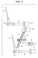
- Fig. 8 is a general connection diagram of a distribution switchgear according to a fourth embodiment of the present invention.
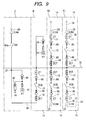
- Fig. 9 is a general connection diagram of an array of panels as distribution switchgear according to a fifth embodiment of the present invention.
- Fig. 10 is a perspective back view of an array of panels as the distribution switchgear shown in Fig. 9 according to an embodiment of the present invention.
- Fig. 11 is a general connection diagram of a distribution switchgear according to a sixth embodiment of the present invention.
- Fig. 12 is a general connection diagram of an array of panels as distribution switchgear according to a seventh embodiment of the present invention.
-
- 1...Housing, 2...Partition plate, 3...Partition plate, 4...Equipment room, 5...Main busbar room, 6...Cable room, 8...Protective control unit, 10...Vacuum circuit breaker, 11...Current transformer, 12...Zero-phase-sequence current transformer, 13...Surge absorber, 14...Equipment unit, 20...Main busbar, 21...Link busbar, 22...Branch busbar, 23...Cable sealing end, 24...Cable, 25... Connecting terminal, 26...Connecting termina1,27...Air disconnection bushing, 28...Air disconnection bushing, 29...Branch busbar, 30...Branch busbar, 31...Connecting terminal, 32...Air disconnection bushing, 33...Connecting terminal, 34...Air disconnection bushing, 35...Connecting busbar, 36...Common room, 80...Disconnecting part, 81a...Disconnector, 81...Voltage transformer, 82...Lightning protector, 84...Auxiliary link busbar.
- In an example of the switchgear of the present invention, an
equipment room 4 and amain busbar room 5 are formed in adistribution panel housing 1 on its front side and on its back side respectively by partitioning; in theequipment room 4,equipment units 14, each comprised of avacuum circuit breaker 10, acurrent transformer 11 on the load side of thevacuum circuit breaker 10 and a zero-phase-sequence current transformer 12 on the power supply side of thevacuum circuit breaker 10, are vertically disposed; and in themain busbar room 5, a solid-insulatedmain busbar 20 disposed along thehousing 1's width direction, a solid-insulatedlink busbar 21 connected with the main busbar and connected with one side of each of theequipment units 14 and solid-insulatedbranch busbars equipment units 14 are disposed. - In order to achieve the above object, distribution switchgear according to the present invention is characterized in that an equipment room and a main busbar room are formed in a distribution panel housing on its front side and on its back side respectively by partitioning; in the equipment room, equipment units, each comprised of a circuit breaker, a current transformer on a load side of the circuit breaker and a zero-phase-sequence current transformer on a power supply side of the circuit breaker, are vertically disposed; and in the main busbar room, a solid-insulated main busbar disposed along the housing's width direction, a solid-insulated link busbar connected with the main busbar and connected with one side of each of the equipment units and a solid-insulated branch busbar connected with the other side of each of the equipment unit are disposed, or characterized by comprising an array of panels disposed side by side in a housing which are a first panel in which two equipment units each comprised of a circuit breaker, a current transformer on a load side of the circuit breaker and a zero-phase-sequence current transformer on a power supply side of the circuit breaker are vertically disposed, a second panel in which an equipment unit comprised of a circuit breaker, a current transformer on a load side of the circuit breaker and a zero-phase-sequence current transformer on a power supply side of the circuit breaker, and a voltage transformer unit having a voltage transformer are vertically disposed, and a third panel in which a voltage transformer unit having a voltage transformer and a lightning protector and a disconnector unit having a disconnector are vertically disposed, wherein these panels are interconnected by a solid-insulated main busbar disposed along the housing's width direction, a solid-insulated link busbar connected with one side of each of the units and a branch busbar connected with the other side of each of the units.
- To provide distribution switchgear which protects the whole load side including a circuit breaker against ground faults to widen the protection range and thereby increases its reliability and can achieve labor saving in maintenance and longer service life.
- An
equipment room 4 and amain busbar room 5 are formed in adistribution panel housing 1 on its front side and on its back side respectively by partitioning; in theequipment room 4,equipment units 14 , each comprised of avacuum circuit breaker 10, acurrent transformer 11 on the load side of thevacuum circuit breaker 10 and a zero-phase-sequence current transformer 12 on the power supply side of thevacuum circuit breaker 10, are vertically disposed; and in themain busbar room 5, a solid-insulatedmain busbar 20 disposed along thehousing 1's width direction, a solid-insulatedlink busbar 21 connected with the main busbar and connected with one side of each of theequipment units 14 and solid-insulatedbranch busbars equipment units 14 are disposed. - According to distribution switchgear in the present invention, since a zero-phase-sequence current transformer is located on the power supply side of a circuit breaker constituting an equipment unit, the whole load side including the circuit breaker can be protected against ground faults to widen the protection range and thereby increase reliability, and also since a solid-insulated main busbar is housed in a main busbar room separate from an equipment room housing equipment units, labor saving in maintenance and longer service life can be achieved.
- Next, distribution switchgear according to embodiments of the present invention will be described referring to drawings.
- Figs. 1 to 5 show distribution switchgear according to a first embodiment of the present invention, in which Fig. 1 is a longitudinal sectional view of distribution switchgear according to an embodiment of the invention, Fig. 2 is a front view of it, Fig. 3 is a partially sectional perspective view of the distribution switchgear shown in Fig.1 according to an embodiment of the invention, Fig. 4 is an enlarged perspective view showing a main busbar of the distribution switchgear shown in Fig. 1 according to an embodiment of the invention, and Fig. 5 is a general connection diagram of distribution switchgear according to an embodiment of the invention.
- In Figs. 1 to 3, the inside of a
housing 1 of the distribution switchgear is partitioned bypartition plates equipment room 4, amain busbar room 5 and acable room 6 are formed in order from the front side (right in the figure). As shown in Figs. 1 and 2, afront door 7 is provided on the front of thehousing 1 in an openable/closable manner. A digitalprotective control unit 8 is mounted on thedoor 7. Aback door 9 is provided on the back of thehousing 1 in an openable/closable manner as shown in Fig. 1. - Inside the
equipment room 4,equipment units 14 are disposed vertically, where they are comprised of vacuum circuit breakers (VCB) 10 arranged side by side along the width direction of the housing 1 (orthogonal to the paper surface of Fig.1), current transformers (CT) 11 provided respectively on the load side of thevacuum circuit breakers 10, zero-phase-sequence current transformers (ZCT) 12 provided respectively on the power supply side of thevacuum circuit breakers 10, and surge absorbers (SA) 13 for protection against external lightning surge (see Fig. 5). - These
equipment units 14 can be drawn out toward the front of the housing 1 (right in Fig. 1) by means ofcarriages 15 at their bottom andguides 16 which guide thecarriages 15. Theseequipment units 14 are usually fixed by lock devices (not shown) and when drawing them frontward, they can be drawn frontward by unlocking the lock devices (not shown) and pullinghandles 17 on the front of theequipment units 14. This means that in the worst case, the equipment can be replaced easily with minimized replacement time. - The
vacuum circuit breaker 10,current transformer 11, and zero-phase-sequencecurrent transformer 12 which constitute anequipment unit 14 as mentioned above are connected in series as shown in Fig. 5. The zero-phase-sequence current transformer 12 is located on the power supply side of thevacuum circuit breaker 10 and thecurrent transformer 11 is located on the load side of thevacuum circuit breaker 10 and the surge absorber 13 for protection against external lightning surge is connected on the load side of thevacuum circuit breaker 10. The current transformer is of the multi current ratio type which can cope with plural rated currents, contributing to increased reliability. - The opening/closing mechanism of the above
vacuum circuit breaker 10 is an electromagnetic operating device which combines an electromagnet and a permanent magnet and uses a solid lubricating bearing in the sliding part of the mechanism, permitting easy greaseless maintenance. - As shown in Fig. 5, a
terminal 18 connected with the fixed electrode side of avacuum circuit breaker 10 and aterminal 19 connected with the movable electrode side of the vacuum circuit breaker are disposed in the back of eachequipment unit 14 ; more particularly in each of the upper andlower equipment units 14 , theterminal 18 is in an upper position and theterminal 19 is below it. Theseterminals link busbar 21 connected with themain busbar 20 in the main busbar room 5 (stated later), andbranch busbars reference numeral 23 represents a cable sealing end andreference numeral 24 represents a cable. - Looking back to Figs. 1 and 3, the solid-insulated
main busbar 20 is disposed midway in the height direction of thehousing 1 along the width direction of thehousing 1 in themain busbar room 5. One end of the solid-insulatedlink busbar 21 is connected with themain busbar 20. The other end of thelink busbar 21 is bifurcated and one connectingterminal 25 of it is led into theequipment room 4 in a way that it can be connected to, or disconnected from, the aboveupper equipment unit 14, and theother terminal 26 is led into theequipment room 4 in a way that it can be connected to, or disconnected from, the abovelower equipment unit 14. These connectingterminals partition plate 2 through air disconnection bushings 27, 28, respectively. - The solid-insulated
branch busbars main busbar room 5, respectively. One connectingterminal 31 of theupper branch busbar 29 is led into theequipment room 4 in a way that it can be connected to, or disconnected from, theterminal 18 of the aboveupper equipment unit 14, and fixed on thepartition plate 2 through an air disconnection bushing 32. The other end of theupper branch busbar 29 is connected with acable sealing end 23 fixed on thepartition plate 3. - One connecting
terminal 33 of thelower branch busbar 30 is led into theequipment room 4 in a way that it can be connected to, or disconnected from, theterminal 19 of the abovelower equipment unit 14, and fixed on thepartition plate 2 through an air disconnection bushing 34. The other end of thelower branch busbar 30 is connected with acable sealing end 23 fixed on thepartition plate 3. The cable sealing ends 23 in thecable room 6 are each connected with a solid-insulatedcable 24. - Fig. 4 shows details of connections of the
main busbar 20,link busbar 21, andbranch busbars partition plates main busbar 20 andlink busbar 21 are connected, for example, by a connectingbusbar 35 which has one end connected with thelink busbar 21 and the other end clamped to themain busbar 20. This arrangement is made taking into assembly and disassembly of these into consideration. Themain busbar 20,link busbar 21,branch busbars main busbar 20,link busbar 21,branch busbars - Next, how the above distribution switchgear according to the first embodiment of the present invention works will be described.
- In this embodiment, since the
current transformer 11 located on the load side of thevacuum circuit breaker 10 and the zero-phase-sequencecurrent transformer 12 located on the power supply side of thevacuum circuit breaker 10 detect a problem in the system such as a ground fault and open thevacuum circuit breaker 10, the whole load side including thevacuum circuit breaker 10 is protected against ground faults to widen the protection range and thereby increase reliability. - In addition, since the solid-insulated
main busbar 20,link busbar 21 andbranch busbars main busbar room 5 behind theequipment room 4 to reduce the insulation distance between the busbars, the housing space is smaller and the whole switchgear can be small. - Furthermore, since the
main busbar 20,link busbar 21,branch busbars - Furthermore, since the
main busbar 20,link busbar 21,branch busbars equipment room 4. Therefore, air purging equipment as incidental equipment can be small and the equipment cost and maintenance cost thereof can be reduced. - As mentioned so far, according to an embodiment of the present invention, the whole load side including a vacuum circuit breaker can be protected against ground faults to widen the protection range and thereby increase reliability and also thanks to the solid-insulated busbars, the insulation performance is less influenced by such factors as atmosphere, environmental condition, and altitude and the risk that the insulators contaminated by dust, salt damage, dew condensation and the like may deteriorate the insulation performance is low, ensuring good safety. In addition, the insulation distance to ground or between phases can be reduced, which offers an advantage that layout for the busbars can be done easily to save space and makes it possible to provide almost ideal distribution switchgear which meets customer needs.
- Fig. 6 is a longitudinal sectional view showing distribution switchgear according to a second embodiment of the present invention and in Fig. 6, those designated by the same reference numerals as in Fig. 1 are the same parts.
- In this embodiment, a
common room 36 replaces the main busbar room and cable room in the first embodiment and thiscommon room 36 is located behind theequipment room 4, and in thiscommon room 36,main busbars 20,link busbars 21,branch busbars cables 24 are disposed. - According to this embodiment, the same effect as in the first embodiment can be achieved and also due to the absence of the
partition plate 3 as shown in Fig. 3, maintainability and assemblability for busbars and the like are improved. - Fig. 7 is a longitudinal sectional view showing distribution switchgear according to a third embodiment of the present invention and in the figure, those designated by the same reference numerals as in Fig. 1 are the same parts.
- In this embodiment, the
cable room 6 in the first embodiment is eliminated and thecables 24 are exposed outside thehousing 1. The rest of the structure is the same as in the embodiment shown in Fig. 1. - According to this embodiment, the same effect as in the above embodiments can be achieved and due to the absence of the
cable room 6, the installation space is smaller, which is helpful for installation in a confined space. - Fig. 8 is a general connection diagram showing distribution switchgear according to a fourth embodiment of the present invention and in the figure, those designated by the same reference numerals as in Figs. 1 to 5 are the same or equivalent parts.
- In this embodiment, disconnecting
parts 80 are provided on the fixed electrode side and movable electrode side of avacuum circuit breaker 10. Like the operating mechanism of thevacuum circuit breaker 10 as mentioned above, the disconnectingpart 80 is operated for disconnection through an electromagnetic operating device which combines an electromagnet and a permanent magnet. A solid lubricating bearing is used in the sliding part of the electromagnetic operating device, permitting easy greaseless maintenance. - In this embodiment, the same effect as in the above embodiments can be achieved as well.
- Figs. 9 and 10 show an example of an array of panels which embodies distribution switchgear as mentioned above according to the present invention, in which Fig. 9 is a general connection diagram thereof and Fig. 10 is a perspective view of the back thereof. In these figures, those designated by the same reference numerals as in Figs. 1 to 5 are the same or equivalent parts.
- In Fig. 9, on the right in the figure, an upper and a
lower equipment unit 14 , each including a vacuum circuit breaker (VCB) 10, disconnectingparts 80 on the fixed electrode and movable electrode sides of thevacuum circuit breaker 10, a current transformer (CT) 11 on the load side of thevacuum circuit breaker 10 and a zero-phase-sequence current transformer (ZCT) 12 on the power supply side of thevacuum circuit breaker 10, constitute a first panel A1 for distribution switchgear; and another first panel A2 with the same structure is placed on the left of the first panel A1; a second panel B is placed on the left of the other first panel A2; and a third panel C is placed on the left of the second panel B, thus constituting an array of panels. - The second panel B includes: an
equipment unit 14, located in its lower portion, which is comprised of a vacuum circuit breaker (VCB) 10, disconnectingparts 80 on the fixed electrode and movable electrode sides of thevacuum circuit breaker 10, a current transformer (CT) 11 on the power supply side of thevacuum circuit breaker 10 and a zero-phase-sequence current transformer (ZCT) 12 on the load side of thevacuum circuit breaker 10; and a voltage transformer unit, located above theequipment unit 14, which is comprised of a voltage transformer (VT) 81 and a disconnectingpart 80. The third panel C includes a voltage transformer unit, located in its lower portion, which is comprised of a voltage transformer (VT) 81, a disconnectingpart 80 and alightning protector 82 and a disconnecting unit, located above the voltage transformer unit, which is comprised of a disconnectingpart 80. - As shown in Fig. 10, these first to third panels A1 to C are interconnected by
main busbars 20, link busbars 2i connected with themain busbars 20,branch busbars auxiliary link busbars 84, at the back of thehousing 1 through anopening 83 in a side face of thehousing 1. - According to this embodiment, it is possible to shorten the construction period for transformation equipment and also substantially reduce the number of on-site man-hours for a new installation or an extension of existing equipment.
- Fig. 11 is a general connection diagram showing distribution switchgear according to a sixth embodiment of the present invention and in the figure, those designated by the same reference numerals as in Figs. 1 to 5 are the same or equivalent parts.
- In this embodiment, a current transformer (CT) 11 and a zero-phase-sequence current transformer (ZCT) 12 are located between the fixed electrode side of a
vacuum circuit breaker 10 and a disconnectingpart 80 and between its movable electrode side and a disconnectingpart 80. Like the operating mechanism of thevacuum breaker 10 as mentioned above, the disconnectingparts 80 are also operated for disconnection through an electromagnetic operating device which combines an electromagnet and a permanent magnet. A solid lubricating bearing is used in the sliding part of the electromagnetic operating device, permitting easy greaseless maintenance. - In this embodiment, the same effect as in the above embodiments can be achieved as well.
- Fig. 12 shows an example of an array of panels which embodies distribution switchgear as mentioned above according to the present invention, which is a variation of the one shown in Fig. 9. In the figure, those designated by the same reference numerals as in Figs. 1 to 5 are the same or equivalent parts.
- In Fig. 12, on the right in the figure, an upper and a
lower equipment unit 14 which each include a vacuum circuit breaker (VCB) 10, disconnectingparts 80 on the fixed electrode and movable electrode sides of thevacuum circuit breaker 10, a current transformer (CT) 11 on the load side of thevacuum circuit breaker 10 and a zero-phase-sequence current transformer (ZCT) 12 on the power supply side of thevacuum circuit breaker 10, both between thevacuum circuit breaker 10 and a disconnectingpart 80, constitute a first panel A1 for distribution switchgear; and another first panel As with the same structure is placed on the left of the first panel A1; a second panel B is placed on the left of the other first panel A2; and a third panel C is placed on the left of the second panel B, thus constituting an array of panels. - The second panel B includes: an
equipment unit 14, located in its lower portion, which is comprised of a vacuum circuit breaker (VCB) 10, disconnectingparts 80 on the fixed electrode and movable electrode sides of thevacuum circuit breaker 10, a current transformer (CT) 11 on the power supply side of thevacuum circuit breaker 10 and a zero-phase-sequence current transformer (ZCT) 12 on the load side of thevacuum circuit breaker 10, both between thevacuum circuit breaker 10 and a disconnectingpart 80; and a voltage transformer unit, located above theequipment unit 14 , which is comprised of a voltage transformer (VT) 81 and a disconnectingpart 80. The third panel C includes a voltage transformer unit, located in its lower portion, which is comprised of a voltage transformer (VT) 81, a disconnectingpart 80 and alightning protector 82, and a disconnector unit, located above the voltage transformer unit, which is comprised of avacuum circuit breaker 90 anddisconnectors 80a on the fixed electrode and movable electrode sides of thevacuum circuit breaker 90. - Like those shown above in Fig. 10, these first to third panels A1 to C are interconnected by
main busbars 20,link busbars 21 connected with themain busbars 20,branch busbars auxiliary link busbars 84, at the back of thehousing 1 through anopening 83 in a side face of thehousing 1. - According to this embodiment, it is possible to shorten the construction period for transformation equipment and also substantially reduce the number of on-site man-hours for a new installation or an extension of existing equipment.
Claims (12)
- A distribution switchgear comprising:an equipment room and a main busbar room, which are formed in a distribution panel housing on its front side and on its back side respectively by partitioning;equipment units disposed in the equipment room, each comprising a circuit breaker, a current transformer on a load side of the circuit breaker and a zero-phase-sequence current transformer on a power supply side of the circuit breaker, the equipment units being vertically arranged; anda solid-insulated main busbar, a solid-insulated link busbar connected with the main busbar and connected with one side of each of the equipment units and a solid-insulated branch busbar connected with the other side of each of the equipment units, the solid-insulated busbar, a solid-insulated link busbar and the solid-insulated branch busbar being disposed along the width direction of the housing.
- A distribution switchgear comprising:an equipment room and a main busbar room and further a cable room are formed in a distribution panel housing on its front side of and on its back side and behind the main busbar room respectively by partitioning;equipment units, each comprising a circuit breaker, a current transformer on a load side of the circuit breaker and a zero-phase-sequence current transformer on a power supply side of the circuit breaker, the equipment units being arranged vertically in the equipment room;a solid-insulated main busbar, a solid-insulated link busbar connected with the main busbar and connected with one side of each of the equipment units and a solid-insulated branch busbar with one end connected with the other side of each of the equipment units and the other end led into the cable room, the solid-insulated main busbar, the solid-insulated link busbar and the solid-insulated branch busbar being disposed in the main busbar room; anda solid-insulated cable connected with the other end of the branch busbar through a cable sealing end in the cable room, is disposed.
- The distribution switchgear as described in claim 1 or 2, wherein the equipment unit further includes a disconnecting part on the power supply side of the circuit breaker.
- A distribution switchgear comprising:an equipment room and a main busbar room are formed in a distribution panel housing on its front side of and on its back side respectively by partitioning;an equipment unit comprising a circuit breaker, a current transformer on a load side of the circuit breaker, a zero-phase-sequence current transformer on a power supply side of the circuit breaker and a disconnecting part,a voltage transformer unit having a voltage transformer and a disconnecting part;wherein the equipment unit and the voltage transformer unit are vertically arranged in the equipment room; anda solid-insulated main busbar, a solid-insulated link busbar connected with the main busbar and connected with one side of the equipment unit and with the voltage transformer unit, and a solid-insulated branch busbar connected with the other side of the equipment unit in the main busbar room, the solid-insulated main busbar, the solid-insulated link busbar and the solid-insulated branch busbar being disposed along the width direction of the housing.
- The distribution switchgear as described in one of claims 1 to 4, wherein the surface of the main busbar, the link busbar, the branch busbar and/or a cable is covered by an earthed layer.
- The distribution switchgear as defined in one of claims 1 to 3, wherein the equipment unit can be connected to, or disconnected from, the main busbar through an air bushing and is housed in the housing on the front side of the housing in a way that it can be drawn out.
- The distribution switchgear as described in one of claims 1 to 3, wherein a protective control unit is mounted on a front door of the housing.
- The distribution switchgear as described in one of claims 1 to 3, wherein the current transformer is of the multi current ratio type which can cope with plural rated currents.
- The distribution switchgear as described in one of claims 1 to 3, wherein an opening/closing mechanism in the equipment unit or the voltage transformer unit is an electromagnetic operating device comprised of an electromagnet and a permanent magnet and a solid lubricating bearing is used for the electromagnetic operating device's sliding part.
- A distribution switchgear characterized by comprising an array of panels disposed side by side in a housing which are:a first panel in which two equipment units each comprised of a circuit breaker, a current transformer on a load side of the circuit breaker and a zero-phase-sequence current transformer on a power supply side of the circuit breaker are vertically disposed;a second panel in which an equipment unit comprised of a circuit breaker, a current transformer on a load side of the circuit breaker and a zero-phase-sequence current transformer on a power supply side of the circuit breaker, and a voltage transformer unit having a voltage transformer are vertically disposed; anda third panel in which a voltage transformer unit having a voltage transformer and a lightning protector and a disconnector unit having a disconnector are vertically disposed,wherein these panels are interconnected by a solid-insulated main busbar disposed along the housing's width direction, a solid-insulated link busbar connected with one side of each of the units and a branch busbar connected with the other side of each of the units.
- The distribution switchgear as described in claim 10, wherein the disconnector of the third panel is a vacuum disconnector.
- The distribution switchgear as described in one of claims 1, 2, 3 or 10, wherein the circuit breaker is a vacuum circuit breaker.
Applications Claiming Priority (1)
| Application Number | Priority Date | Filing Date | Title |
|---|---|---|---|
| JP2006189159 | 2006-07-10 |
Publications (2)
| Publication Number | Publication Date |
|---|---|
| EP1879275A1 true EP1879275A1 (en) | 2008-01-16 |
| EP1879275B1 EP1879275B1 (en) | 2014-02-12 |
Family
ID=38610692
Family Applications (1)
| Application Number | Title | Priority Date | Filing Date |
|---|---|---|---|
| EP07012820.2A Not-in-force EP1879275B1 (en) | 2006-07-10 | 2007-06-29 | Distribution switchgear |
Country Status (6)
| Country | Link |
|---|---|
| US (1) | US7518851B2 (en) |
| EP (1) | EP1879275B1 (en) |
| KR (1) | KR20080005869A (en) |
| CN (1) | CN101119013A (en) |
| SG (1) | SG139639A1 (en) |
| TW (1) | TW200814480A (en) |
Cited By (1)
| Publication number | Priority date | Publication date | Assignee | Title |
|---|---|---|---|---|
| EP2144343A3 (en) * | 2008-07-07 | 2012-08-15 | Hitachi Ltd. | Solid insulated bus switchgear |
Families Citing this family (25)
| Publication number | Priority date | Publication date | Assignee | Title |
|---|---|---|---|---|
| US7786384B2 (en) * | 2008-08-29 | 2010-08-31 | Mauricio Diaz | Efficient high-ampacity bowl-shaped tubular conductors |
| JP4727736B2 (en) * | 2009-02-19 | 2011-07-20 | 株式会社日立製作所 | Switchgear |
| KR101270869B1 (en) * | 2009-02-23 | 2013-06-05 | 미쓰비시덴키 가부시키가이샤 | Method and device for diagnosing remaining lifetime of switchgear |
| JP4866949B2 (en) * | 2009-09-07 | 2012-02-01 | 株式会社日立製作所 | Vacuum insulated switchgear |
| JP5026537B2 (en) * | 2010-02-03 | 2012-09-12 | 株式会社日立製作所 | Switchgear |
| US8237535B2 (en) | 2010-04-16 | 2012-08-07 | World Properties, Inc. | Integral planar transformer and busbar |
| JP5471925B2 (en) * | 2010-07-16 | 2014-04-16 | 株式会社日立製作所 | Disconnector with earthing switch |
| KR101013582B1 (en) * | 2010-09-24 | 2011-02-14 | 보국전기공업 주식회사 | Switchgear with door opener and shock absorber |
| KR101013587B1 (en) * | 2010-09-24 | 2011-02-14 | 보국전기공업 주식회사 | Switchgear with insulated terminal socket and insulated terminal socket |
| KR101013580B1 (en) * | 2010-09-24 | 2011-02-14 | 보국전기공업 주식회사 | Switchboard with sensor |
| KR101013585B1 (en) * | 2010-09-24 | 2011-02-14 | 보국전기공업 주식회사 | Switchgear with insulated bus and insulated bus |
| EP2495833A1 (en) * | 2011-03-02 | 2012-09-05 | ABB Technology AG | Solid insulated busbar arrangement, especially for medium voltage switchgear |
| EP2738893B1 (en) | 2011-07-29 | 2017-02-01 | Mitsubishi Electric Corporation | Closed distribution panel |
| JP5921269B2 (en) * | 2012-03-14 | 2016-05-24 | 株式会社日立製作所 | Switchgear |
| KR101279894B1 (en) * | 2012-04-03 | 2013-06-28 | 엘에스산전 주식회사 | Switch for solid insulated switchgear |
| KR20140123007A (en) | 2013-04-11 | 2014-10-21 | 주식회사 엘지화학 | Battery Cell Having Round Corner |
| JP2015043656A (en) * | 2013-08-26 | 2015-03-05 | 株式会社東芝 | Circuit breaker |
| WO2015064118A1 (en) * | 2013-10-30 | 2015-05-07 | 三菱電機株式会社 | Current transformer support device, and switchgear using said current transformer support device |
| US9306351B2 (en) * | 2014-02-14 | 2016-04-05 | Huawei Technologies Co., Ltd. | Power distribution connection apparatus |
| US9577412B2 (en) * | 2014-06-24 | 2017-02-21 | General Electric Company | Switchgear housing including a floating exhaust flap assembly |
| US10965105B2 (en) | 2019-03-07 | 2021-03-30 | Consolidated Edison Company Of New York, Inc. | Partition covers for electric distribution equipment enclosures |
| KR102623588B1 (en) * | 2023-03-14 | 2024-01-10 | 주식회사 다온이엔지 | Earthquake-resistant switchgear system |
| PL4443462T3 (en) * | 2023-04-03 | 2026-04-07 | Eaton Intelligent Power Limited | Compact switching device |
| CN220190140U (en) * | 2023-07-03 | 2023-12-15 | 广东维能电气有限公司 | Combined type longitudinal rotary cabinet with side overhead wire inlet and outlet modes |
| CN118920320A (en) * | 2024-07-30 | 2024-11-08 | 广东维能电气有限公司 | Longitudinally-rotating movable indoor alternating-current metal closed switch equipment |
Citations (3)
| Publication number | Priority date | Publication date | Assignee | Title |
|---|---|---|---|---|
| JPH0711813U (en) | 1993-07-14 | 1995-02-21 | 株式会社高岳製作所 | Metal closed switchgear |
| JP2003189422A (en) | 2001-12-21 | 2003-07-04 | Mitsubishi Electric Corp | Switchgear unit for switchboard |
| US20060034025A1 (en) | 2004-08-10 | 2006-02-16 | Hideki Masuhara | Switching device for power distribution |
Family Cites Families (13)
| Publication number | Priority date | Publication date | Assignee | Title |
|---|---|---|---|---|
| US3967165A (en) * | 1975-03-25 | 1976-06-29 | General Electric Company | Switchboard apparatus having control wiring passageways |
| AU3060977A (en) * | 1976-12-14 | 1979-05-24 | Tokyo Shibaura Electric Co | Enclosure for electrical apparatus |
| US4136374A (en) * | 1976-12-30 | 1979-01-23 | Westinghouse Electric Corp. | Electrical switchboard apparatus including double-flanged vertical riser conductors |
| JPS58186303A (en) * | 1982-04-23 | 1983-10-31 | 株式会社日立製作所 | switchboard |
| JPS60102803A (en) * | 1983-11-08 | 1985-06-07 | 株式会社東芝 | Enclosed switchboard |
| JPS61112503A (en) * | 1984-11-06 | 1986-05-30 | 株式会社東芝 | Closed switchboard |
| FR2573570B1 (en) * | 1984-11-22 | 1988-05-27 | Merlin Gerin | POLARIZED ELECTROMAGNETIC RELAY WITH MAGNETIC LOCKING FOR A TRIGGER OF AN ELECTRIC CIRCUIT BREAKER |
| US4713642A (en) * | 1986-05-07 | 1987-12-15 | Westinghouse Electric Corp. | Face connected instrument transformer |
| JPH0711813A (en) | 1993-06-16 | 1995-01-13 | Japan Hardware Kk | Joint lock |
| US5539614A (en) * | 1993-09-29 | 1996-07-23 | Mitsubishi Denki Kabushiki Kaisha | Control unit, plug-in unit, transformer, zero-phase current transformer, and frequency measuring circuit applied to control center |
| US5450280A (en) * | 1994-01-18 | 1995-09-12 | Powell Electrical Manufacturing Company | Voltage transformer disconnect grounding system |
| US5648888A (en) * | 1995-12-27 | 1997-07-15 | Hydro-Quebec | Power distribution substation |
| JP3063720B2 (en) * | 1997-12-12 | 2000-07-12 | 日本電気株式会社 | Busbar structure with noise filter function |
-
2007
- 2007-05-22 TW TW096118162A patent/TW200814480A/en not_active IP Right Cessation
- 2007-06-28 SG SG200704864-8A patent/SG139639A1/en unknown
- 2007-06-29 EP EP07012820.2A patent/EP1879275B1/en not_active Not-in-force
- 2007-07-05 CN CNA2007101282378A patent/CN101119013A/en active Pending
- 2007-07-09 US US11/774,786 patent/US7518851B2/en not_active Expired - Fee Related
- 2007-07-09 KR KR1020070068706A patent/KR20080005869A/en not_active Ceased
Patent Citations (3)
| Publication number | Priority date | Publication date | Assignee | Title |
|---|---|---|---|---|
| JPH0711813U (en) | 1993-07-14 | 1995-02-21 | 株式会社高岳製作所 | Metal closed switchgear |
| JP2003189422A (en) | 2001-12-21 | 2003-07-04 | Mitsubishi Electric Corp | Switchgear unit for switchboard |
| US20060034025A1 (en) | 2004-08-10 | 2006-02-16 | Hideki Masuhara | Switching device for power distribution |
Cited By (1)
| Publication number | Priority date | Publication date | Assignee | Title |
|---|---|---|---|---|
| EP2144343A3 (en) * | 2008-07-07 | 2012-08-15 | Hitachi Ltd. | Solid insulated bus switchgear |
Also Published As
| Publication number | Publication date |
|---|---|
| TWI354421B (en) | 2011-12-11 |
| SG139639A1 (en) | 2008-02-29 |
| TW200814480A (en) | 2008-03-16 |
| US20080007896A1 (en) | 2008-01-10 |
| US7518851B2 (en) | 2009-04-14 |
| EP1879275B1 (en) | 2014-02-12 |
| CN101119013A (en) | 2008-02-06 |
| KR20080005869A (en) | 2008-01-15 |
Similar Documents
| Publication | Publication Date | Title |
|---|---|---|
| EP1879275B1 (en) | Distribution switchgear | |
| US8008594B2 (en) | Vacuum insulated switchgear | |
| EP1903592B1 (en) | Vacuum insulated switchgear | |
| JP4268991B2 (en) | Vacuum insulated switchgear | |
| KR101030290B1 (en) | Solid insulated busbar switchgear | |
| KR101051113B1 (en) | Vacuum insulated switchgear | |
| EP2104127B1 (en) | Switchgear | |
| CN102570340A (en) | Switchgear | |
| US11637414B2 (en) | Three phase switchgear using single phase equipment in single casing | |
| UA63961C2 (en) | Multiterminal breaker cell; method of constructing the switchgear system of a primary substation containing at least one multiterminal breaker cell; switchgear system of a primary substation | |
| JP5275263B2 (en) | Switchgear system | |
| JP4333774B2 (en) | Switchgear for power distribution | |
| JP5026537B2 (en) | Switchgear | |
| CN103329376B (en) | Vacuum insulation switchgear and method for replacing mold switch | |
| WO2023235505A1 (en) | Isolated load electrical distribution enclosure | |
| JPH0556520A (en) | Power receiving/transforming system | |
| EP2144342B1 (en) | Drawout door interface for circuit breaker | |
| HK1117946A (en) | Distribution switchgear | |
| Bode | Switchgear for 2000 and beyond |
Legal Events
| Date | Code | Title | Description |
|---|---|---|---|
| PUAI | Public reference made under article 153(3) epc to a published international application that has entered the european phase |
Free format text: ORIGINAL CODE: 0009012 |
|
| AK | Designated contracting states |
Kind code of ref document: A1 Designated state(s): AT BE BG CH CY CZ DE DK EE ES FI FR GB GR HU IE IS IT LI LT LU LV MC MT NL PL PT RO SE SI SK TR |
|
| AX | Request for extension of the european patent |
Extension state: AL BA HR MK YU |
|
| 17P | Request for examination filed |
Effective date: 20080331 |
|
| AKX | Designation fees paid |
Designated state(s): DE FR |
|
| 17Q | First examination report despatched |
Effective date: 20121212 |
|
| GRAP | Despatch of communication of intention to grant a patent |
Free format text: ORIGINAL CODE: EPIDOSNIGR1 |
|
| INTG | Intention to grant announced |
Effective date: 20130724 |
|
| GRAS | Grant fee paid |
Free format text: ORIGINAL CODE: EPIDOSNIGR3 |
|
| GRAP | Despatch of communication of intention to grant a patent |
Free format text: ORIGINAL CODE: EPIDOSNIGR1 |
|
| GRAA | (expected) grant |
Free format text: ORIGINAL CODE: 0009210 |
|
| INTG | Intention to grant announced |
Effective date: 20131216 |
|
| RIN1 | Information on inventor provided before grant (corrected) |
Inventor name: KAJIYAMA, YUKO, HITACHI, LTD. Inventor name: NISHIZAWA, YOSHINORI, HITACHI, LTD. Inventor name: TSUCHIYA, KENJI, HITACHI, LTD. |
|
| AK | Designated contracting states |
Kind code of ref document: B1 Designated state(s): DE FR |
|
| REG | Reference to a national code |
Ref country code: DE Ref legal event code: R096 Ref document number: 602007035036 Country of ref document: DE Effective date: 20140327 |
|
| REG | Reference to a national code |
Ref country code: DE Ref legal event code: R097 Ref document number: 602007035036 Country of ref document: DE |
|
| PLBE | No opposition filed within time limit |
Free format text: ORIGINAL CODE: 0009261 |
|
| STAA | Information on the status of an ep patent application or granted ep patent |
Free format text: STATUS: NO OPPOSITION FILED WITHIN TIME LIMIT |
|
| 26N | No opposition filed |
Effective date: 20141113 |
|
| REG | Reference to a national code |
Ref country code: DE Ref legal event code: R097 Ref document number: 602007035036 Country of ref document: DE Effective date: 20141113 |
|
| REG | Reference to a national code |
Ref country code: FR Ref legal event code: PLFP Year of fee payment: 10 |
|
| PGFP | Annual fee paid to national office [announced via postgrant information from national office to epo] |
Ref country code: DE Payment date: 20160622 Year of fee payment: 10 |
|
| PGFP | Annual fee paid to national office [announced via postgrant information from national office to epo] |
Ref country code: FR Payment date: 20160516 Year of fee payment: 10 |
|
| REG | Reference to a national code |
Ref country code: DE Ref legal event code: R119 Ref document number: 602007035036 Country of ref document: DE |
|
| REG | Reference to a national code |
Ref country code: FR Ref legal event code: ST Effective date: 20180228 |
|
| PG25 | Lapsed in a contracting state [announced via postgrant information from national office to epo] |
Ref country code: DE Free format text: LAPSE BECAUSE OF NON-PAYMENT OF DUE FEES Effective date: 20180103 |
|
| PG25 | Lapsed in a contracting state [announced via postgrant information from national office to epo] |
Ref country code: FR Free format text: LAPSE BECAUSE OF NON-PAYMENT OF DUE FEES Effective date: 20170630 |