EP1879007A2 - Leak detection sensor system and method for double carcass hose - Google Patents
Leak detection sensor system and method for double carcass hose Download PDFInfo
- Publication number
- EP1879007A2 EP1879007A2 EP07013803A EP07013803A EP1879007A2 EP 1879007 A2 EP1879007 A2 EP 1879007A2 EP 07013803 A EP07013803 A EP 07013803A EP 07013803 A EP07013803 A EP 07013803A EP 1879007 A2 EP1879007 A2 EP 1879007A2
- Authority
- EP
- European Patent Office
- Prior art keywords
- sensor
- assembly
- sensor casing
- axial bore
- housing
- Prior art date
- Legal status (The legal status is an assumption and is not a legal conclusion. Google has not performed a legal analysis and makes no representation as to the accuracy of the status listed.)
- Granted
Links
- 238000001514 detection method Methods 0.000 title claims abstract description 38
- 238000000034 method Methods 0.000 title claims description 6
- 239000012530 fluid Substances 0.000 claims abstract description 63
- 238000007789 sealing Methods 0.000 claims abstract description 30
- 230000008878 coupling Effects 0.000 claims abstract description 27
- 238000010168 coupling process Methods 0.000 claims abstract description 27
- 238000005859 coupling reaction Methods 0.000 claims abstract description 27
- 238000004891 communication Methods 0.000 claims abstract description 15
- 230000000712 assembly Effects 0.000 claims description 7
- 238000000429 assembly Methods 0.000 claims description 7
- 230000003287 optical effect Effects 0.000 description 20
- 239000000835 fiber Substances 0.000 description 10
- 238000012544 monitoring process Methods 0.000 description 10
- 239000013307 optical fiber Substances 0.000 description 9
- 230000005540 biological transmission Effects 0.000 description 8
- 238000010276 construction Methods 0.000 description 8
- XLYOFNOQVPJJNP-UHFFFAOYSA-N water Substances O XLYOFNOQVPJJNP-UHFFFAOYSA-N 0.000 description 8
- 230000008859 change Effects 0.000 description 7
- 239000013535 sea water Substances 0.000 description 6
- 238000007667 floating Methods 0.000 description 5
- 210000003128 head Anatomy 0.000 description 4
- 210000002445 nipple Anatomy 0.000 description 4
- 230000006835 compression Effects 0.000 description 3
- 238000007906 compression Methods 0.000 description 3
- 238000013500 data storage Methods 0.000 description 3
- 230000014759 maintenance of location Effects 0.000 description 3
- 230000007257 malfunction Effects 0.000 description 3
- 238000004519 manufacturing process Methods 0.000 description 3
- 230000008439 repair process Effects 0.000 description 3
- 238000013022 venting Methods 0.000 description 3
- 239000003795 chemical substances by application Substances 0.000 description 2
- 238000013480 data collection Methods 0.000 description 2
- 230000000694 effects Effects 0.000 description 2
- 238000007689 inspection Methods 0.000 description 2
- 239000000463 material Substances 0.000 description 2
- 230000008054 signal transmission Effects 0.000 description 2
- 230000011664 signaling Effects 0.000 description 2
- 238000003860 storage Methods 0.000 description 2
- 239000012815 thermoplastic material Substances 0.000 description 2
- 230000000007 visual effect Effects 0.000 description 2
- 229910000831 Steel Inorganic materials 0.000 description 1
- 230000009471 action Effects 0.000 description 1
- 230000004913 activation Effects 0.000 description 1
- 238000004873 anchoring Methods 0.000 description 1
- 210000002159 anterior chamber Anatomy 0.000 description 1
- 238000013473 artificial intelligence Methods 0.000 description 1
- 239000011324 bead Substances 0.000 description 1
- 230000000903 blocking effect Effects 0.000 description 1
- 230000003139 buffering effect Effects 0.000 description 1
- 239000011248 coating agent Substances 0.000 description 1
- 238000000576 coating method Methods 0.000 description 1
- 230000001010 compromised effect Effects 0.000 description 1
- 230000007547 defect Effects 0.000 description 1
- 230000007812 deficiency Effects 0.000 description 1
- 230000001419 dependent effect Effects 0.000 description 1
- 238000013461 design Methods 0.000 description 1
- 238000010586 diagram Methods 0.000 description 1
- 238000009826 distribution Methods 0.000 description 1
- 230000007613 environmental effect Effects 0.000 description 1
- 238000004880 explosion Methods 0.000 description 1
- 238000011065 in-situ storage Methods 0.000 description 1
- 238000003780 insertion Methods 0.000 description 1
- 230000037431 insertion Effects 0.000 description 1
- 125000006850 spacer group Chemical group 0.000 description 1
- 239000010959 steel Substances 0.000 description 1
- 238000006467 substitution reaction Methods 0.000 description 1
- 230000009897 systematic effect Effects 0.000 description 1
- 229920001169 thermoplastic Polymers 0.000 description 1
- 239000004416 thermosoftening plastic Substances 0.000 description 1
- 238000012546 transfer Methods 0.000 description 1
- 210000000707 wrist Anatomy 0.000 description 1
Images




Classifications
-
- G—PHYSICS
- G01—MEASURING; TESTING
- G01M—TESTING STATIC OR DYNAMIC BALANCE OF MACHINES OR STRUCTURES; TESTING OF STRUCTURES OR APPARATUS, NOT OTHERWISE PROVIDED FOR
- G01M3/00—Investigating fluid-tightness of structures
- G01M3/02—Investigating fluid-tightness of structures by using fluid or vacuum
- G01M3/26—Investigating fluid-tightness of structures by using fluid or vacuum by measuring rate of loss or gain of fluid, e.g. by pressure-responsive devices, by flow detectors
- G01M3/28—Investigating fluid-tightness of structures by using fluid or vacuum by measuring rate of loss or gain of fluid, e.g. by pressure-responsive devices, by flow detectors for pipes, cables or tubes; for pipe joints or seals; for valves ; for welds
- G01M3/2807—Investigating fluid-tightness of structures by using fluid or vacuum by measuring rate of loss or gain of fluid, e.g. by pressure-responsive devices, by flow detectors for pipes, cables or tubes; for pipe joints or seals; for valves ; for welds for pipes
- G01M3/283—Investigating fluid-tightness of structures by using fluid or vacuum by measuring rate of loss or gain of fluid, e.g. by pressure-responsive devices, by flow detectors for pipes, cables or tubes; for pipe joints or seals; for valves ; for welds for pipes for double-walled pipes
-
- G—PHYSICS
- G01—MEASURING; TESTING
- G01M—TESTING STATIC OR DYNAMIC BALANCE OF MACHINES OR STRUCTURES; TESTING OF STRUCTURES OR APPARATUS, NOT OTHERWISE PROVIDED FOR
- G01M3/00—Investigating fluid-tightness of structures
- G01M3/02—Investigating fluid-tightness of structures by using fluid or vacuum
- G01M3/04—Investigating fluid-tightness of structures by using fluid or vacuum by detecting the presence of fluid at the leakage point
- G01M3/042—Investigating fluid-tightness of structures by using fluid or vacuum by detecting the presence of fluid at the leakage point by using materials which expand, contract, disintegrate, or decompose in contact with a fluid
- G01M3/045—Investigating fluid-tightness of structures by using fluid or vacuum by detecting the presence of fluid at the leakage point by using materials which expand, contract, disintegrate, or decompose in contact with a fluid with electrical detection means
- G01M3/047—Investigating fluid-tightness of structures by using fluid or vacuum by detecting the presence of fluid at the leakage point by using materials which expand, contract, disintegrate, or decompose in contact with a fluid with electrical detection means with photo-electrical detection means, e.g. using optical fibres
-
- G—PHYSICS
- G01—MEASURING; TESTING
- G01M—TESTING STATIC OR DYNAMIC BALANCE OF MACHINES OR STRUCTURES; TESTING OF STRUCTURES OR APPARATUS, NOT OTHERWISE PROVIDED FOR
- G01M3/00—Investigating fluid-tightness of structures
- G01M3/38—Investigating fluid-tightness of structures by using light
-
- F—MECHANICAL ENGINEERING; LIGHTING; HEATING; WEAPONS; BLASTING
- F16—ENGINEERING ELEMENTS AND UNITS; GENERAL MEASURES FOR PRODUCING AND MAINTAINING EFFECTIVE FUNCTIONING OF MACHINES OR INSTALLATIONS; THERMAL INSULATION IN GENERAL
- F16L—PIPES; JOINTS OR FITTINGS FOR PIPES; SUPPORTS FOR PIPES, CABLES OR PROTECTIVE TUBING; MEANS FOR THERMAL INSULATION IN GENERAL
- F16L33/00—Arrangements for connecting hoses to rigid members; Rigid hose-connectors, i.e. single members engaging both hoses
- F16L33/01—Arrangements for connecting hoses to rigid members; Rigid hose-connectors, i.e. single members engaging both hoses specially adapted for hoses having a multi-layer wall
Definitions
- the invention relates generally to offshore oil load and discharge terminals and, more specifically, to hose leak detection systems deployed within the context of such oil load and discharge terminals.
- a "single carcass hose” is a hose construction comprising only one carcass layer. Leakage from a single carcass hose may occur from a precipitous hose failure or a failure that materializes over time. Hose failure may result from overpressure of the system, a puncture from outside, sudden tensile break of the hose body, defects in the manufacture, construction or design of the hose, etc. In a single carcass hose construction, hose failure results in immediate oil leakage to the environment surrounding the hose. Such leakage is highly undesirable for obvious environmental and economic reasons.
- a double carcass hose construction utilizes an outer hose carcass confining an inner hose carcass as an added safeguard.
- the outer hose functions to hold any oil or fluid that leaks through the inner hose carcass for a certain designed period of time.
- a hose includes a main pressure cord or carcass layer as a primary confinement and an outer, or auxiliary, pressure cord layer formed so as to sheathe the inner carcass.
- a buffering space is defined between the carcass layers to retain fluid that leaks from the inner carcass.
- US-A- 5,244, 016 discloses a hose representative of the state of the art double carcass construction.
- a double carcass hose is generally produced and utilized in two different types: submarine or floating configurations, depending on the type of application and offshore oil load and discharge system.
- Submarine applications require that a hose extend in submerged fashion between two points whereas a floating application requires that the hose extend across the water surface. In either application, leakage from the hose results in the aforementioned undesirable consequences.
- Existing leak monitoring systems and devices may fail to provide accurate monitored data under certain other conditions.
- the leak detection devices themselves may be electrically unsafe in that they have active or power components within the oil collection space, creating a fire or explosion risk.
- the communication systems in existing systems provide, at times, unreliable communication between the sensing elements and remote receivers or visual observers.
- the positioning of the sensors may also be affected by the floating hose line torsion when deploying the hose line into the water.
- the sensors may also be positioned incorrectly during hose line segment assembly.
- hose lines move as a result of seawater and weather conditions and such movement can cause sensor position change/failure, or cause erroneous data collection by the monitoring agent.
- Additional deficiencies in existing art sensing systems are that they are relatively large, expensive to manufacture, cumbersome to deploy, and provide a less than satisfactory degree of reliability and flexibility.
- Available systems typically provide one means of communicating the leak status of a hose segment or coupling.
- a mechanical sensor is used in some available systems but such sensors require constant physical checking by inspectors. The sensors communicate visually, such as by means of a flashing LED. Such systems require on-site inspections which can be expensive and dangerous under certain conditions.
- the leak detectors in the industry communicate by signal transmission to a remote receiver. However, the efficacy of signal transmission may be compromised, depending on operating conditions, interference, and whether the sensor is above or below the water. The use of one form of communication or another is dependent on the needs and preferences of the user.
- No existing system provides a leak detection sensor assembly that can readily adapt to preferences of the user as to leak detection communication.
- existing leak detection systems readily facilitate a replacement of faulty or malfunctioning sensor components should the need arise.
- some of existing sensor assemblies in available leak detection systems may be integrally incorporated into a hose segment or the nipple at the end of the hose. As such, the sensor assemblies may be inaccessible for replacement service, or repair.
- removal of existing sensor assemblies from a host hose segment may compromise the integrity of the hose segment or make the hose segment vulnerable to incursion of seawater while the sensor assembly is detached for repairs.
- the industry is in need of a flexible leak detector and system that is reliable, safe, efficient, and cost effective to manufacture, deploy, and maintain.
- a desired system will accurately provide leak detection data despite rough operational conditions and minimize data collection and transmission failures.
- the system will provide a sensor assembly that can readily adapt to communication preferences of the user.
- the needs of the industry are additionally for a sensor assembly that is accessible and that may be readily replaced in the case of a malfunction or type changeover preferred by the end user.
- Such a sensor assembly should further be capable of temporary or permanent removal from a host hose segment without compromising the integrity of the hose segment or leaving the hose segment vulnerable to incursion of seawater.
- the subject invention includes a housing defined by sidewalls externally mountable to a hose line segment and having an internal housing chamber in fluid communication with a hose line segment collection space.
- a sensor casing having an axial bore mounts through a sensor housing sidewall, and includes an external sensor casing portion positioned outside of the sensor housing and an internal sensor casing portion positioned inside of the sensor housing.
- a valve assembly within the sensor casing opens and closes responsive to coupling and decoupling a sensor assembly to the external sensor casing portion, the sensor assembly including fluid detection means for detecting the presence of fluid within the sensor casing axial bore.
- a first sealing unit of the valve assembly is positioned at a remote end of the axial bore, the first sealing unit opening from a closed position at or above a preset threshold pressure whereby admitting external fluid into the axial bore and closing at a pressure below the preset threshold pressure.
- a second sealing unit of the valve assembly positioned inwardly along the axial bore, opens responsive to coupling engagement between the sensor assembly and the external sensor casing portion and closes responsive to disengagement of the sensor assembly from the external sensor casing portion.
- a biasing spring is provided for biasing the first and second sealing units into respective closed positions.
- valve assembly admits fluid at or above a preset threshold pressure into the axial bore.
- valve assembly includes biasing means for biasing the valve assembly into the closed position.
- the sensor assembly in coupled engagement with the external sensor casing portion places the valve assembly into the open position.
- the sensor assembly fluid detection means may comprise at least one optical fiber positioned to contact fluid within the axial bore.
- the valve assembly comprises a second sealing unit positioned at an inward location within the axial bore, the second sealing unit opening from a closed position to admit fluid passage along the axial bore when the sensor assembly is coupled with the external sensor casing portion and closing to block fluid passage along the axial bore when the sensor assembly is uncoupled from the external sensor casing portion.
- the valve assembly may further include biasing means for biasing the first and second sealing units into respective closed positions.
- the valve assembly biasing means may comprise a spring positioned axially within the axial bore.
- the first and second sealing units comprise first and second balls positioned within the axial bore on opposite respective ends of the spring, the first ball sealing against a forward annular shoulder defining a forward end of the axial bore and the second ball sealing against a rearward annular shoulder defining an internal portion of the axial bore, the spring in compression between the first and second balls biasing the first and second balls against respective annular shoulders.
- a method for detecting leaks in a hose line segment including: mounting a housing externally to the hose line segment, the housing defined by sidewalls and having an internal housing chamber in fluid communication with a collection space between inner and outer hose layers; mounting an elongate sensor casing through at least one sensor housing sidewall, the sensor casing having an axial bore and including an external sensor casing portion positioned outside the sensor housing and an internal sensor casing portion positioned inside of the sensor housing; locating a valve assembly within the sensor casing, the valve assembly closing to prohibiting fluid passage through the axial bore and opening to allow fluid passage through the axial bore; coupling a sensor assembly with the external sensor casing portion, the sensor assembly including a fluid detector.
- the sensor assembly opens the valve assembly upon coupling engagement with the external sensor casing portion and closes the valve assembly upon uncoupling from the external sensor casing portion.
- the valve assembly may include a first sealing unit positioned at a remote end of the axial bore, the first sealing unit opening from a closed position at or above a preset threshold pressure into the axial bore and closing at a pressure below the preset threshold pressure.
- the valve assembly may include a second sealing unit positioned at an inward location within the axial bore, the second sealing unit opening responsive to coupling engagement between the sensor assembly and the external sensor casing portion and closing responsive to disengagement of the sensor assembly from the external sensor casing portion; and the valve assembly may include a biasing spring for biasing the first and second sealing units into respective closed positions.
- an offshore oil loading and discharge terminal is depicted by way of example incorporating a double carcass hose with built-in electronic remote oil leak detection system 10 configured pursuant to the subject invention.
- the offshore oil loading and discharge terminal of FIG. 7 is but one of many applications for the invention and the invention is not intended to be limited thereto. Any application in which a double carcass hose is utilized for the transportation of a fluid can utilize the subject leak detection system and the teachings herein set forth.
- FIG. 7 schematically represents a tanker or platform 12. Extending from the tanker 12 is a network of submerged hose lines 14 comprising end to end connected hose segments 16 joined together by a coupling 18. Hose lines 14, while illustrated as submersible, may also be configured as floating lines if desired for an intended application.
- the submerged lines 14 extend to a buoy 20 and connect thereto by a coupling 21.
- Submarine hose lines 22 depend from buoy 20 and comprise hose segments 24 connected end to end by couplings 26.
- Submarine hose lines 22 terminate at a pump station 28. Oil is pumped from station 28 upward through hose lines 22 to the lines 14 and therein to the tanker 12.
- leak detection sensors are disposed within the hose lines 14 and 22 to detect fluid leakage and prevent the fluid from escaping into the sea.
- each hose segment is provided with two sensors, one at each end. More or fewer sensors per hose line or hose line segment may be deployed if desired.
- a transmitter 30 may be mounted to the buoy 20 and coupled to the sensors in each hose segment 24. Data indicating the leak status of each hose segment is communicated to the transmitter and transmitted via satellite 32 to a central data processor/receiver 36 connected to antenna 34. The receiver 34 distributes the data to one or more decentralized remote terminal locations 38 so that the status of the hose lines 14, 22 may be monitored. Alternatively, or in conjunction with the data distribution to terminals 38, data relating to leaks may be downloaded into a main computer storage and website access provided thereto as will be explained.
- leak detectors suitable for use in the subject system are illustrated.
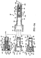
- the system may utilize alternatively configured leak detectors 42, 44, 46 in conjunction with a common casing assembly 40.
- Mechanical leak detector assembly 42; optical leak detector assembly 44; and telemetry leak detector assembly 46 interchangeably couple with the casing assembly 40 to provide a flexible system that, depending on a customer's choice, different ways of monitoring oil leak through the first carcass of a double carcass hose may be achieved.
- three optional configurations for detecting leaks, assemblies 42, 44, 46, other types of leak detection devices may be employed (not shown) with the casing assembly 40 in addition thereto without departing from the invention.
- a forward pressure valve assembly 48 is disposed within a tubular rigid casing 50 of the casing assembly 40.
- the valve assembly 48 denies leaking fluid from the hose segment admittance into the casing 50 unless a prescribed pressure threshold is exceeded.
- the valve assembly 48 also prevents external water from migrating through the casing 50 and into the hose from the opposite direction.
- the casing 50 readily interchangeably couples with each variety of leak detection assembly 42, 44, 46 to meet the needs of the user as well as to facilitate replacement of malfunctioning detector components should the need arise.
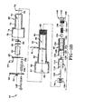
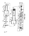
- FIGS. 3B and 3C illustrate in exploded view the optical version of the leak detection assembly 44.
- the assembly forms a generally cylindrical device combining the leak detection assembly 44 and the casing assembly 40.
- An end plate 52 has an LED housing 54 projecting rearwardly therefrom.
- An LED circuit board 56 of a type available to the industry drives an LED 58 that fits within the housing 54.
- a long cycle battery 60 is disposed forward of the board 56 and rearward of transmitter circuit board 64.
- An O-ring seal 62 is disposed between the battery 60 and the board 64.
- the circuit board 64 is of a type commonly available and includes a micro-radio frequency transmitter and a micro-ultrasonic transmitter (in the telemetry version depicted by FIGS. 2A and 2B) as well as an optical signal generating circuitry in the optical version.
- the detection system is encapsulated into a casing 69, preferably although not necessarily formed of thermoplastic material.
- the casing 69 is generally cylindrical having a smaller diameter forward nose portion 70 and a larger diameter rearward head portion 74.
- a center axial passageway 72 projects through the casing 69 from end to end, beginning at an access orifice 76 at a forward end.
- An O-ring seal 78 is disposed forward and surrounds a forward end of the detector housing 69.
- the detector assembly 44 as well as the other two detector assembly versions 42, 46, are interchangeable, each being configured for insertion into the casing 50.
- Casing 50 is formed of a rigid material, preferably steel.
- the casing 50 is generally tubular and elongate, and includes a forward smaller diameter forward nose portion 80, an intermediate external screw threaded portion 82, a transverse assembly bore 84 adjacent the threaded portion 82, and a rearward enlarged head portion 86.
- the head portion 86 is formed to provide LED portals 88 sized to admit and retain an LED 58 as best seen in FIG. 3A.
- the casing 50 has an axial passageway 90 therethrough from end to end and an internally threaded forward end 92.
- a cylindrical optics support 94 formed of preferably thermoplastic material having a pair of rearwardly directed optics connector sockets 96, 98 and a transverse assembly bore extending therethrough.
- a pair of optics receiving passageways 102, 104 extend from a forward end of the support 94, through the support to respective sockets 96, 98.
- the passageways 102, 104 are sized to receive respective legs 108, 110 of optic fiber loop 106.
- the legs 108, 110 project through the support 94 to the sockets 96, 98. So located, the loop 106 projects forward from the support 94.
- An actuator member 112 is formed as cylindrical body 114 having central body cavity 115.
- a pair of tines 116 project rearward from the periphery of the body 114.
- a pin projection 118 is axially disposed on the central axis of body 114 and projects rearward.
- the pressure valve assembly 48 includes a generally tubular elongate body 120 formed of suitable material such as thermoplastic.
- the body 120 has a rearward enlarged cavity 122 dimensioned to receive the actuator body 114 therein.
- a forward elongate valve cavity 124 extends to an anterior chamber 126 at the forward end of the body 120.
- the valve cavity 124 communicates with the enlarged cavity 122 by means of relatively narrow passageway 128.
- External threaded portion 130 is located about the medial portion of body 120 and internal threaded surface 132 surrounds the anterior cavity 126.
- the cavity 124 is sized to seat first and second valve balls 134, 136 and a spring member 138 situated between the balls.
- An end retention screw 140 is provided and screws into the forward end of the body 120.
- the retention screw 140 has a small bore axial passageway 142 that extends into screw head 146, along the body of the screw to the cavity 124.
- the ball 136 seats against the internal opening of the passageway 142 and the ball 134 seats against the internal opening of the passageway 128.
- Spring 138 in compression nominally biases the balls 134, 136 against their respective openings with a preset level of force as will be explained below.
- An assembly pin 148 is further provided with a spacer sleeve 150 and a pin retainer 152.
- the casing 69 receives the circuit board 64 therein until optical fiber sockets 66 protrude from opening 76.
- O-ring 78 mounts and seats over the forward end of the casing 69.
- Battery 60 inserts within the nose portion 70 of the body 69 followed by the LED electronics board 56.
- One or more signaling LEDs project out of board 56 and are aligned to reside within opening 75 of the casing 69.
- the end plate 52 encloses the rearward end of the body 69 and is secured by means of pin 148 extending through sleeve 150 to the retention cap 152.
- the assembly 44 is upon completion of assembly in condition for detachable coupling to the casing assembly 50.
- Casing assembly 40 is assembled by positioning the optical support body 94 within passageway 90, and securing the body 94 into position by the extension of pin 81 through the body transverse passage 100.
- the optical loop ends extend through passages 102, 104 respectively of the support body 94 to the sockets 96, 98.
- the actuation member 112 is inserted within the passage 90 and tines 114,116 of the member 112 are positioned within the passageway 90 to abut body 94.
- the body 112 is received within chamber 122 of the pressure valve body 120 and pin projection 118 extends through passageway 128 to abut ball 134.
- the assembled optical detector assembly 44 couples to the casing assembly 40 by screw threaded attachment.
- optical connectors 66, 68 align with and enter into sockets 96, 98 respectively of the optics support body 94.
- an optical signal may be generated by electronic circuitry of board 64 and transmitted through the optical fiber loop 106.
- the forward end of the casing nose portion 70 upon reaching the terminal location within casing 80, will contact the support body 94 and push the body 94 forward, Such forward movement will cause pin projection 118 to move forward and move valve ball 134 forward. Ball 134 will thus be unseated, opening the passageway 128 between chambers 122, 124. Valve ball 136 remains seated against the passageway 142 through screw 140.
- the pressure valve by appropriate selection of screw 138, may be set to open at a low pressure, for example 90 psi. If the oil force exceeds the threshold, the oil will force ball 136 away from the internal opening of passageway 142 into an open position. Oil may then travel inside the cavity 124 through passageway 128 and cavity 122 to the internal chamber 115 of the body 112 wherein the optical loop 106 resides. Upon reaching the optical loop 106, the oil modifies the optical transmission properties of fiber. The electronic analysis of the optical transmission through the loop 106 determines an oil leak has occurred and the sensor starts the LED(s) 58.
- the occurrence and detection of a leak may further be stored as data within a passive RFID chip located on the board 56.
- Passive RFID chips that is requiring no energy source to function, are commonly available electronic devices. At the appropriate time, data stored inside the RFID chip may be retrieved as explained below.
- the sensor assembly 44 may be disconnected from the casing assembly 40 by threaded detachment. Upon disassociation of the sensor assembly 44 from the casing assembly 40, the spring 138 will release from compression to force ball 134 into sealing engagement with passageway 128. If the sensor assembly is in an underwater environment, water from outside of the sensor will thus be prevented from entering passageway 124 and proceeding therefrom out the forward end of passageway 142.
- the pressure valve assembly 48 accordingly operates to open to allow leaking oil to access the optical fiber 106 when a leak occur and to close whenever the leak detection assembly (42, 44, 46) is uncoupled from the casing assembly 40.
- FIGS. 3A and FIG. 5 show alternative mechanical versions of a leak detection assembly.
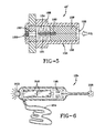
- the mechanical sensor assembly 154 of FIG. 5 includes a cylindrical body 156 having a sliding piston member 158 within an axial passageway 161.
- the piston 158 moves within the passageway between forward and rearward positions.
- a magneto 160 Secured to the piston is a magneto 160 that moves with the piston between the forward and rearward positions.
- a forward opening 162 extends through the forward end of body 156 and communicates with axial passage 161.
- a coil spring 164 surrounds the piston 158 within the body 156 and biases the sliding piston to the forward side of the passageway 161.
- the body 156 has external screw threads for coupling with the casing assembly 40 and a rubber end cap 168 that includes an axial air venting passageway that extends to chamber 161. If an oil leak occurs through the first carcass of a hose, the oil will move between the two carcasses until it reaches the forward end of the assembly 154. The oil forces the sliding piston 158 rearward and the magneto 160 moves rearward with the piston.
- the location of the magneto 160 may be externally determined by a reader and from the location of the magneto 160 a determination may be made that a leak has occurred. As described above with reference to the optical leak detection assembly 44, the occurrence and detection of a leak may further be stored as data within a passive RFID chip (not shown). Passive RFID chips, that is, requiring no energy source to function, are commonly available electronic devices. At the appropriate time, data stored inside the RFID chip may be retrieved as explained below.
- FIG. 3A shows an alternative configuration for a mechanical leak detector 42.
- the detector 42 includes a tubular body 170 having an axial passage 171.
- a piston 172 is slideably housed within passage 171 and moves between forward and rearward positions.
- a magneto 174 is secured to the piston 172 and moves therewith.
- An end plug 176 is located within a forward portion of passage 171 and includes a passageway 178.
- a sealing O-ring 180 is affixed about the plug 176 to seal off the passage 171.
- a coil spring 182 is situated within the passage 171 between a piston head 183 and end plate 52.
- a venting passageway 184 branches from passage 171 to a venting orifice 188 in the end plate 52.
- a valve ball 190 is positioned to seat against a lower segment 191 of the passageway 184 and is biased into a closed engagement by biasing spring 192.
- a sensor reader and data storage device 194 is shown schematically.
- the reader includes a read head 196 that is electrically connected to circuit board electronics 198 powered by batteries 200.
- the detection of movement rearward of the magneto 174 will be detected by head 196 and the electronic circuitry will cause an activation of LED indicator light 202.
- data indicative of the detection of a leak, an identification of the particular leak detection assembly detecting the leak may be stored in the device 194.
- the sensor reader and data storage device 194 provides a waterproof case, magnetic read head, electronic processor and data storage chip, long life battery and indicator LED.
- a wrist strap 204 may be provided for safely holding the unit.
- the inspector approximates the read head to the leak detector and the reader checks the RFID chip.
- the unit then reads and records the data stored in the RFID chip.
- the LED may be wired to flash to show the reading is completed.
- the data recorded in the reader may be downloaded into a computer system as part of the offshore hose line monitoring system. Such data may then be available through an internet or intranet website.
- the telemetry leak detection assembly 46 may likewise be used in conjunction with the casing assembly 40 as will be appreciated from FIG. 3A.
- Assembly 46 is constructed similar to assembly 44 in that optical fiber connectors 66, 68 protrude forward from optics circuit board 64.
- An O-ring seal 62 renders a storage compartment waterproof for a battery 60.
- Electronics board 56 controls the operation of micro-ultrasonic transmitter 57 and micro-radio transmitter 59.
- Sensing the presence of a leak with the telemetry assembly unit 46 is a described above with regard to the optical assembly 44.
- the presence of oil surrounding fiber 106 will cause optical properties of the fiber 106 to change. The change is detected and interpreted as evidencing a leak.
- the transmitters 57, 59 may then transmit data to a remote receiver identifying by means of a passive RFID chip within the assembly 46 the location of the leak, hose identification data, etc.
- a double carcass hose 204 is depicted consisting of an inner carcass 206, an outer carcass 208 extending to a carcass forward end 210, and a collection space 212 between the carcass layers 206,208.
- a connector 214 is affixed to each end of the hose 204 and includes a nipple or sleeve 218 that is positioned along the axial inner surface of the inner carcass 206.
- An elongate fluid collection housing 218 is positioned to extend along the outside of the connector sleeve 216 parallel with the axis of the hose 204.
- the housing 218 includes annular anchoring beads 220 that mechanically connects the duct into the outer carcass layer 208 proximate forward end 210.
- the housing 218 is shown to include a top wall 222 and a forward end wall 224.
- a sensor assembly 42, 44, 46 coupled to casing assembly 40 mounts preferably although not necessarily in the end wall 224 of the housing 218.
- the senor (42, 44, or 46) within casing assembly 40 is intended to protrude through the wall 224 of the housing 218.
- the sensor head portion 86 remains outside of the housing 218 as the sensor is affixed by means of screw threads 82 into a threaded aperture within wall 224. So positioned the transmission elements 57, 59 are outside of the mounting wall 224.
- the sensing element 42, 44, or 46 projects into the housing 224 and the optical fiber (or plural fibers) 106, within the casing assembly 40 resides within the housing 224. While one housing 224 and one sensor assembly 42, 44, 46/casing assembly 40 is shown in FIG. 4, a plurality of sensors may be positioned about the periphery of the hose, each coupling with a respective housing 224.
- fluid leakage from the inner carcass 206 or water entering the hose as a result of a breach in the outer carcass 208, will migrate into the collection space 212, eventually reaching and entering the forward end of the sensor 42, 44, 46/casing assembly 40.
- the pressure valve assembly 48 will open when the pressure of the fluid against the valve assembly exceeds a pressure threshold.
- the pressure valve assembly 48 opens fluid will enter into the axial passageway through the casing assembly 40 until reaching the optical fiber loop(s) 106.
- the escaping oil, or water will contact the fiber 106.
- Contact between the fiber outer coating and the fluid will alter the transmission properties carried by the fiber 106 and be interpreted by the optical electronics circuitry mounted on board 64 as a leak.
- the electronics will then initiate a change in communication signal to indicate a breach by means of the ultrasonic transmitter 57 and/or the RF transmitter 59.
- a visual indicator change at signaling LED 58 will occur.
- the mechanical leak detector 42 is deployed, the mechanical detector will change position and indicate the existence of a leak to the sensor reader 194.
- the optical sensing element 106 is passive, and does not have or need an active energy supply, making the element 106 intrinsically safer when contacting oil than other forms of sensing devices.
- the wall 224 through which the sensor 42, 44, or 46 mounts thus functionally isolates the passive sensing element 106 from the battery powered analysis element 56 and transmission elements 57, 59.
- the system is relatively light and occupies minimal space. The replacement of a malfunctioning sensor is readily facilitated by removing the end plate of the sensing unit. Substitution of one sensor type (42, 44, 46) for a different sensor type is also readily facilitated in like manner should a malfunction occur or the needs of the user change.
- the optical fiber operates as a contacting medium for detecting the presence of fluid and is a reliable means for detecting the presence and identity of fluid in the space 212.
- the analysis element 56 is powered by durable long duration battery 60.
- the element 56 operates continuously without need for a timer and functions preferably using artificial intelligence or neural network software.
- the transmission elements 57, 59 include built-in replaceable batteries and ID chips. When data is collected and transmitted, the identity of the sensor/hose segment is provided with the data to a remote receiver. Corrective action to repair the leaking hose can then be taken.
- the transmission elements 57, 59 work under magnetic principle with no electrical contacts.
- the subject embodiment presents a housing 218 defined by sidewalls 222, 224 that externally mounts to the hose line segment 204.
- the internal housing chamber is in fluid communication with the hose line segment collection space 212.
- the sensor casing 40 mounts through the sensor housing endwall 224, and includes the external sensor casing portion 86 positioned outside of the sensor housing 218 and the internal sensor casing portion 50 positioned inside of the sensor housing 218.
- the pressure valve assembly within the sensor casing portion 50 opens and closes responsive to coupling and decoupling the sensor assembly (42, 44, or 46) to the external sensor casing portion 86.
- the fiber optic loop 106 detects the presence of fluid within the sensor casing axial bore as described previously.
- the first sealing unit, ball 136, of the pressure valve assembly is positioned at a remote end of the axial bore chamber 124, and opens from a closed position at or above a preset threshold pressure whereby admitting external fluid into the axial bore chamber 124 and closing at a pressure below the preset threshold pressure.
- the second sealing unit, ball 134, of the valve assembly is positioned inwardly along the axial bore chamber 124, and opens responsive to coupling engagement between the sensor assembly (42, 44, or 46) and the external sensor casing portion 50 and closes responsive to disengagement of the sensor assembly from the external sensor casing portion.
- the biasing spring 138 biases the first and second sealing ball units 134,136 in opposite directions into their respective closed positions.
- a method for detecting leaks in a hose line segment including: mounting the housing 218 externally to the hose line segment 204, with the housing internal chamber in fluid communication with the hose collection space 212; mounting the elongate sensor casing 40 through a housing endwall 224 such that an external sensor casing portion 86 is positioned outside the sensor housing and an internal sensor casing portion 50 is positioned inside of the sensor housing; locating the pressure valve assembly within the sensor casing 80, the valve assembly closing to prohibiting fluid passage through the axial bore, chamber 124, and opening to allow fluid passage through the axial bore chamber 124; coupling a sensor assembly (42, 44, or 46) with the external sensor casing portion 50, the sensor assembly including the fluid detector 106.
- the sensor assembly (42, 44, 46) opens the valve assembly upon coupling engagement with the external sensor casing portion 50 and closes the valve assembly upon uncoupling from the external sensor casing portion 50.
- the valve assembly first sealing ball unit 136 is positioned at a remote end of the axial bore chamber 124 and opens the chamber 124 at or above a preset threshold pressure and closes the chamber 124 at a pressure below the preset threshold pressure.
- the second sealing ball unit 134 is positioned at an inward location within the axial bore chamber 124 and opens responsive to coupling engagement between the sensor assembly and the external sensor casing portion and closes responsive to disengagement of the sensor assembly from the external sensor casing portion.
- the ball 134 prevents external seawater from passing through the chamber 124 into the collection housing 218 and therefrom into the hose 204.
- Ball 136 seals against the internal forward end of the chamber 124 and assists in blocking external fluid from passing through the chamber 124 and into the hose 204.
- the biasing spring 138 maintains the balls 134, 136 in their respective closed positions.
- the assembly thus allows for replacement of the sensor units 42, 44, 46 by decoupling the sensor unit from the casing.
- the system provides a sensor assembly that can readily adapt to communication preferences of the user by interchanging sensor units 42, 44, 46 into a universal casing assembly.
- the sensor assembly (42, 44, 46) is accessible and may be readily replaced in the case of a malfunction.
- the sensor assembly (42,44,46) is further be capable of temporary or permanent removal from a host hose segment 204 without compromising the integrity of the hose segment 204 or leaving the hose segment vulnerable to incursion of seawater.
- the pressure valve assembly thus controls the passage of external seawater into the hose and controls the admittance of fluid leaking from the hose into the sensing unit unless the pressure threshold is exceeded.
Landscapes
- Physics & Mathematics (AREA)
- General Physics & Mathematics (AREA)
- Examining Or Testing Airtightness (AREA)
- Rigid Pipes And Flexible Pipes (AREA)
Abstract
Description
- The invention relates generally to offshore oil load and discharge terminals and, more specifically, to hose leak detection systems deployed within the context of such oil load and discharge terminals.
- In offshore oil load and discharge operations, there is a systematic risk of oil leakage to the sea from damage to single carcass submarine or floating oil suction and discharge hoses. As used herein, a "single carcass hose" is a hose construction comprising only one carcass layer. Leakage from a single carcass hose may occur from a precipitous hose failure or a failure that materializes over time. Hose failure may result from overpressure of the system, a puncture from outside, sudden tensile break of the hose body, defects in the manufacture, construction or design of the hose, etc. In a single carcass hose construction, hose failure results in immediate oil leakage to the environment surrounding the hose. Such leakage is highly undesirable for obvious environmental and economic reasons.
- Because of the risk of failure inherent in single carcass hose construction, a "double carcass" hose construction has been proposed and developed by those in the industry. A double carcass hose construction utilizes an outer hose carcass confining an inner hose carcass as an added safeguard. The outer hose functions to hold any oil or fluid that leaks through the inner hose carcass for a certain designed period of time. In a typical double carcass construction, a hose includes a main pressure cord or carcass layer as a primary confinement and an outer, or auxiliary, pressure cord layer formed so as to sheathe the inner carcass. A buffering space is defined between the carcass layers to retain fluid that leaks from the inner carcass. In use, it is common to connect hoses end-to-end to form a hose line for transporting oil or other fluid under pressure.
US-A- 5,244, 016 discloses a hose representative of the state of the art double carcass construction. - A double carcass hose is generally produced and utilized in two different types: submarine or floating configurations, depending on the type of application and offshore oil load and discharge system. Submarine applications require that a hose extend in submerged fashion between two points whereas a floating application requires that the hose extend across the water surface. In either application, leakage from the hose results in the aforementioned undesirable consequences.
- In order to minimize the damage resulting from an undetected leak, various leak detection systems have been proposed and adopted. Such systems generally employ leak detectors of various configurations, operable under varying principles, mounted at the nipple region of an underwater hose connection.
US-A- 5,654,499 teaches a detector mounted to an end of a hose for detecting fluid upon contact between a sensing medium and the fluid.US-A-4,465,105 teaches a pressure sensitive switch for detecting by means of measuring the pressure of leakage fluid between carcass layers.US-A-5,714,681 discloses an electro-optical sensor that utilizes an infrared beam that senses fluid levels when the beam is deflected. - In general, in offshore oil transfer hose lines using double carcass hoses, there is a constant physical check of hose and leak detectors required because most leak detectors are mechanical devices. The existence of an oil leak must be manually or visually confirmed by checking each leak detector. Consequently, a constant monitoring of each hose line is required. Such monitoring activities may be done by the oil company itself or a contract service provider. The monitoring entity keeps records and files detailing monitoring activity and typically hand-writes such records "in-situ". However, local conditions may make it difficult for the monitoring entity to annotate data observed. Operational conditions may further be such (e.g. high seas) that there is substantial danger to operational personnel and also a risk that incorrect data will be observed and collected by the monitoring agent.
- Existing leak monitoring systems and devices, therefore, while working well under benign conditions, may fail to provide accurate monitored data under certain other conditions. The leak detection devices themselves may be electrically unsafe in that they have active or power components within the oil collection space, creating a fire or explosion risk. Secondly, the communication systems in existing systems provide, at times, unreliable communication between the sensing elements and remote receivers or visual observers. The positioning of the sensors may also be affected by the floating hose line torsion when deploying the hose line into the water. The sensors may also be positioned incorrectly during hose line segment assembly. Finally hose lines move as a result of seawater and weather conditions and such movement can cause sensor position change/failure, or cause erroneous data collection by the monitoring agent.
- Additional deficiencies in existing art sensing systems are that they are relatively large, expensive to manufacture, cumbersome to deploy, and provide a less than satisfactory degree of reliability and flexibility. Available systems typically provide one means of communicating the leak status of a hose segment or coupling. A mechanical sensor is used in some available systems but such sensors require constant physical checking by inspectors. The sensors communicate visually, such as by means of a flashing LED. Such systems require on-site inspections which can be expensive and dangerous under certain conditions. Alternatively, the leak detectors in the industry communicate by signal transmission to a remote receiver. However, the efficacy of signal transmission may be compromised, depending on operating conditions, interference, and whether the sensor is above or below the water. The use of one form of communication or another is dependent on the needs and preferences of the user. No existing system provides a leak detection sensor assembly that can readily adapt to preferences of the user as to leak detection communication. Nor can existing leak detection systems readily facilitate a replacement of faulty or malfunctioning sensor components should the need arise. Finally, some of existing sensor assemblies in available leak detection systems may be integrally incorporated into a hose segment or the nipple at the end of the hose. As such, the sensor assemblies may be inaccessible for replacement service, or repair. Moreover, removal of existing sensor assemblies from a host hose segment may compromise the integrity of the hose segment or make the hose segment vulnerable to incursion of seawater while the sensor assembly is detached for repairs.
- Accordingly, the industry is in need of a flexible leak detector and system that is reliable, safe, efficient, and cost effective to manufacture, deploy, and maintain. A desired system will accurately provide leak detection data despite rough operational conditions and minimize data collection and transmission failures. Ideally, the system will provide a sensor assembly that can readily adapt to communication preferences of the user. The needs of the industry are additionally for a sensor assembly that is accessible and that may be readily replaced in the case of a malfunction or type changeover preferred by the end user. Such a sensor assembly should further be capable of temporary or permanent removal from a host hose segment without compromising the integrity of the hose segment or leaving the hose segment vulnerable to incursion of seawater.
- The subject invention according to one aspect includes a housing defined by sidewalls externally mountable to a hose line segment and having an internal housing chamber in fluid communication with a hose line segment collection space. A sensor casing having an axial bore mounts through a sensor housing sidewall, and includes an external sensor casing portion positioned outside of the sensor housing and an internal sensor casing portion positioned inside of the sensor housing. A valve assembly within the sensor casing opens and closes responsive to coupling and decoupling a sensor assembly to the external sensor casing portion, the sensor assembly including fluid detection means for detecting the presence of fluid within the sensor casing axial bore.
- Pursuant to a further aspect of the invention, a first sealing unit of the valve assembly is positioned at a remote end of the axial bore, the first sealing unit opening from a closed position at or above a preset threshold pressure whereby admitting external fluid into the axial bore and closing at a pressure below the preset threshold pressure. A second sealing unit of the valve assembly, positioned inwardly along the axial bore, opens responsive to coupling engagement between the sensor assembly and the external sensor casing portion and closes responsive to disengagement of the sensor assembly from the external sensor casing portion. A biasing spring is provided for biasing the first and second sealing units into respective closed positions.
- According to a further aspect of the invention, the valve assembly admits fluid at or above a preset threshold pressure into the axial bore.
- In a preferred embodiment, the valve assembly includes biasing means for biasing the valve assembly into the closed position.
- In yet a further preferred embodiment, the sensor assembly in coupled engagement with the external sensor casing portion places the valve assembly into the open position.
- The sensor assembly fluid detection means may comprise at least one optical fiber positioned to contact fluid within the axial bore.
- According to a further aspect of the invention, the valve assembly comprises a second sealing unit positioned at an inward location within the axial bore, the second sealing unit opening from a closed position to admit fluid passage along the axial bore when the sensor assembly is coupled with the external sensor casing portion and closing to block fluid passage along the axial bore when the sensor assembly is uncoupled from the external sensor casing portion.
- The valve assembly may further include biasing means for biasing the first and second sealing units into respective closed positions.
- The valve assembly biasing means may comprise a spring positioned axially within the axial bore.
- In a preferred embodiment, the first and second sealing units comprise first and second balls positioned within the axial bore on opposite respective ends of the spring, the first ball sealing against a forward annular shoulder defining a forward end of the axial bore and the second ball sealing against a rearward annular shoulder defining an internal portion of the axial bore, the spring in compression between the first and second balls biasing the first and second balls against respective annular shoulders.
- According to another aspect of the invention, a method for detecting leaks in a hose line segment is provided, the method including: mounting a housing externally to the hose line segment, the housing defined by sidewalls and having an internal housing chamber in fluid communication with a collection space between inner and outer hose layers; mounting an elongate sensor casing through at least one sensor housing sidewall, the sensor casing having an axial bore and including an external sensor casing portion positioned outside the sensor housing and an internal sensor casing portion positioned inside of the sensor housing; locating a valve assembly within the sensor casing, the valve assembly closing to prohibiting fluid passage through the axial bore and opening to allow fluid passage through the axial bore; coupling a sensor assembly with the external sensor casing portion, the sensor assembly including a fluid detector. The sensor assembly opens the valve assembly upon coupling engagement with the external sensor casing portion and closes the valve assembly upon uncoupling from the external sensor casing portion. The valve assembly may include a first sealing unit positioned at a remote end of the axial bore, the first sealing unit opening from a closed position at or above a preset threshold pressure into the axial bore and closing at a pressure below the preset threshold pressure. The valve assembly may include a second sealing unit positioned at an inward location within the axial bore, the second sealing unit opening responsive to coupling engagement between the sensor assembly and the external sensor casing portion and closing responsive to disengagement of the sensor assembly from the external sensor casing portion; and the valve assembly may include a biasing spring for biasing the first and second sealing units into respective closed positions.
- The invention will be described by way of example and with reference to the accompanying drawings in which:
- FIG. 1 is an assembled perspective view of a leak detector constructed pursuant to the invention;
- FIG. 2A is a longitudinal sectional view through the leak detector of FIG. 1 taken along the
line 2A-2A; - FIG. 2B is a longitudinal sectional view through the leak detector of FIG. 1 taken along the
line 2B-2B; - FIG. 3A is a longitudinal exploded sectional view of the casing assembly and representative three sensor assemblies compatible therewith pursuant to the invention;
- FIG. 3B is an exploded sectional view of the LED sensor assembly;
- FIG. 3C is an exploded perspective view of the LED sensor assembly rotated ninety degrees from the position depicted in FIG. 3B;
- FIG. 4 is a longitudinal side elevation view shown in partial section of a house and nipple section having a leak detector attached thereto pursuant to the invention;
- FIG. 5 is a longitudinal sectional view through a mechanical sensor assembly configured pursuant to the invention;
- FIG. 6 is a plan view of a representative reader unit pursuant to the invention; and
- FIG. 7 is a representation of one leak detection system diagram configured pursuant to the invention.
- Referring initially to FIG. 7, an offshore oil loading and discharge terminal is depicted by way of example incorporating a double carcass hose with built-in electronic remote oil
leak detection system 10 configured pursuant to the subject invention. The offshore oil loading and discharge terminal of FIG. 7 is but one of many applications for the invention and the invention is not intended to be limited thereto. Any application in which a double carcass hose is utilized for the transportation of a fluid can utilize the subject leak detection system and the teachings herein set forth. - FIG. 7 schematically represents a tanker or
platform 12. Extending from thetanker 12 is a network of submerged hose lines 14 comprising end to end connected hose segments 16 joined together by acoupling 18. Hose lines 14, while illustrated as submersible, may also be configured as floating lines if desired for an intended application. The submerged lines 14 extend to abuoy 20 and connect thereto by acoupling 21.Submarine hose lines 22 depend frombuoy 20 and comprisehose segments 24 connected end to end bycouplings 26.Submarine hose lines 22 terminate at apump station 28. Oil is pumped fromstation 28 upward throughhose lines 22 to the lines 14 and therein to thetanker 12. Pursuant to the invention, as explained in detail below, leak detection sensors are disposed within thehose lines 14 and 22 to detect fluid leakage and prevent the fluid from escaping into the sea. Preferably, although not necessarily, each hose segment is provided with two sensors, one at each end. More or fewer sensors per hose line or hose line segment may be deployed if desired. - A
transmitter 30 may be mounted to thebuoy 20 and coupled to the sensors in eachhose segment 24. Data indicating the leak status of each hose segment is communicated to the transmitter and transmitted viasatellite 32 to a central data processor/receiver 36 connected toantenna 34. Thereceiver 34 distributes the data to one or more decentralized remoteterminal locations 38 so that the status of the hose lines 14, 22 may be monitored. Alternatively, or in conjunction with the data distribution toterminals 38, data relating to leaks may be downloaded into a main computer storage and website access provided thereto as will be explained. - With reference to FIGS. 1 and 3A, leak detectors suitable for use in the subject system are illustrated. The system may utilize alternatively configured
leak detectors common casing assembly 40. Mechanicalleak detector assembly 42; opticalleak detector assembly 44; and telemetryleak detector assembly 46 interchangeably couple with thecasing assembly 40 to provide a flexible system that, depending on a customer's choice, different ways of monitoring oil leak through the first carcass of a double carcass hose may be achieved. While three optional configurations for detecting leaks,assemblies casing assembly 40 in addition thereto without departing from the invention. - A forward
pressure valve assembly 48 is disposed within a tubularrigid casing 50 of thecasing assembly 40. Thevalve assembly 48 denies leaking fluid from the hose segment admittance into thecasing 50 unless a prescribed pressure threshold is exceeded. Thevalve assembly 48 also prevents external water from migrating through thecasing 50 and into the hose from the opposite direction. Thecasing 50 readily interchangeably couples with each variety ofleak detection assembly - With reference to FIGS. 1, 2A, 2B, 3A, 3B, and 3C, the component assembly of the
leak detector assemblies leak detection assembly 44. The assembly forms a generally cylindrical device combining theleak detection assembly 44 and thecasing assembly 40. Anend plate 52 has an LEDhousing 54 projecting rearwardly therefrom. AnLED circuit board 56 of a type available to the industry drives anLED 58 that fits within thehousing 54. Along cycle battery 60 is disposed forward of theboard 56 and rearward oftransmitter circuit board 64. An O-ring seal 62 is disposed between thebattery 60 and theboard 64. - Extending forward from the
board 64 are a pair ofoptical fiber connectors circuit board 64 is of a type commonly available and includes a micro-radio frequency transmitter and a micro-ultrasonic transmitter (in the telemetry version depicted by FIGS. 2A and 2B) as well as an optical signal generating circuitry in the optical version. The detection system is encapsulated into acasing 69, preferably although not necessarily formed of thermoplastic material. Thecasing 69 is generally cylindrical having a smaller diameter forwardnose portion 70 and a larger diameter rearwardhead portion 74. A centeraxial passageway 72 projects through thecasing 69 from end to end, beginning at anaccess orifice 76 at a forward end. An O-ring seal 78 is disposed forward and surrounds a forward end of thedetector housing 69. - The
detector assembly 44, as well as the other twodetector assembly versions casing 50.Casing 50 is formed of a rigid material, preferably steel. Thecasing 50 is generally tubular and elongate, and includes a forward smaller diameter forwardnose portion 80, an intermediate external screw threadedportion 82, a transverse assembly bore 84 adjacent the threadedportion 82, and a rearwardenlarged head portion 86. Thehead portion 86 is formed to provideLED portals 88 sized to admit and retain anLED 58 as best seen in FIG. 3A. Thecasing 50 has anaxial passageway 90 therethrough from end to end and an internally threadedforward end 92. - A
cylindrical optics support 94 formed of preferably thermoplastic material is provided having a pair of rearwardly directedoptics connector sockets optics receiving passageways support 94, through the support torespective sockets passageways respective legs optic fiber loop 106. Thelegs support 94 to thesockets loop 106 projects forward from thesupport 94. - An
actuator member 112 is formed ascylindrical body 114 havingcentral body cavity 115. A pair oftines 116 project rearward from the periphery of thebody 114. Apin projection 118 is axially disposed on the central axis ofbody 114 and projects rearward. - The
pressure valve assembly 48 includes a generally tubularelongate body 120 formed of suitable material such as thermoplastic. Thebody 120 has a rearwardenlarged cavity 122 dimensioned to receive theactuator body 114 therein. A forwardelongate valve cavity 124 extends to an anterior chamber 126 at the forward end of thebody 120. Thevalve cavity 124 communicates with theenlarged cavity 122 by means of relativelynarrow passageway 128. External threadedportion 130 is located about the medial portion ofbody 120 and internal threadedsurface 132 surrounds the anterior cavity 126. Thecavity 124 is sized to seat first andsecond valve balls spring member 138 situated between the balls. Anend retention screw 140 is provided and screws into the forward end of thebody 120. Theretention screw 140 has a small boreaxial passageway 142 that extends intoscrew head 146, along the body of the screw to thecavity 124. Theball 136 seats against the internal opening of thepassageway 142 and theball 134 seats against the internal opening of thepassageway 128.Spring 138 in compression nominally biases theballs assembly pin 148 is further provided with aspacer sleeve 150 and apin retainer 152. - Assembly of the
optical version 44 of the leak detection assembly will be readily appreciated from FIGS. 3B, 3C. Thecasing 69 receives thecircuit board 64 therein untiloptical fiber sockets 66 protrude from opening 76. O-ring 78 mounts and seats over the forward end of thecasing 69.Battery 60 inserts within thenose portion 70 of thebody 69 followed by theLED electronics board 56. One or more signaling LEDs project out ofboard 56 and are aligned to reside within opening 75 of thecasing 69. Theend plate 52 encloses the rearward end of thebody 69 and is secured by means ofpin 148 extending throughsleeve 150 to theretention cap 152. Theassembly 44 is upon completion of assembly in condition for detachable coupling to thecasing assembly 50. -
Casing assembly 40 is assembled by positioning theoptical support body 94 withinpassageway 90, and securing thebody 94 into position by the extension ofpin 81 through the bodytransverse passage 100. The optical loop ends extend throughpassages support body 94 to thesockets actuation member 112 is inserted within thepassage 90 and tines 114,116 of themember 112 are positioned within thepassageway 90 toabut body 94. Thebody 112 is received withinchamber 122 of thepressure valve body 120 andpin projection 118 extends throughpassageway 128 toabut ball 134. - The assembled
optical detector assembly 44 couples to thecasing assembly 40 by screw threaded attachment. As forward end of thecasing nose portion 70 reaches a terminal location within thecasing 80,optical connectors sockets body 94. So situated, an optical signal may be generated by electronic circuitry ofboard 64 and transmitted through theoptical fiber loop 106. The forward end of thecasing nose portion 70, upon reaching the terminal location within casing 80, will contact thesupport body 94 and push thebody 94 forward, Such forward movement will causepin projection 118 to move forward and movevalve ball 134 forward.Ball 134 will thus be unseated, opening thepassageway 128 betweenchambers Valve ball 136 remains seated against thepassageway 142 throughscrew 140. - If an oil leak occurs through a hose carcass, oil will move between the two carcasses until it reaches the
assembly spring 140 and thepressure valve assembly 48. The pressure valve, by appropriate selection ofscrew 138, may be set to open at a low pressure, for example 90 psi. If the oil force exceeds the threshold, the oil will forceball 136 away from the internal opening ofpassageway 142 into an open position. Oil may then travel inside thecavity 124 throughpassageway 128 andcavity 122 to theinternal chamber 115 of thebody 112 wherein theoptical loop 106 resides. Upon reaching theoptical loop 106, the oil modifies the optical transmission properties of fiber. The electronic analysis of the optical transmission through theloop 106 determines an oil leak has occurred and the sensor starts the LED(s) 58. The occurrence and detection of a leak may further be stored as data within a passive RFID chip located on theboard 56. Passive RFID chips, that is requiring no energy source to function, are commonly available electronic devices. At the appropriate time, data stored inside the RFID chip may be retrieved as explained below. - It will be appreciated that the
sensor assembly 44 may be disconnected from thecasing assembly 40 by threaded detachment. Upon disassociation of thesensor assembly 44 from thecasing assembly 40, thespring 138 will release from compression to forceball 134 into sealing engagement withpassageway 128. If the sensor assembly is in an underwater environment, water from outside of the sensor will thus be prevented from enteringpassageway 124 and proceeding therefrom out the forward end ofpassageway 142. Thepressure valve assembly 48 accordingly operates to open to allow leaking oil to access theoptical fiber 106 when a leak occur and to close whenever the leak detection assembly (42, 44, 46) is uncoupled from thecasing assembly 40. - FIGS. 3A and FIG. 5 show alternative mechanical versions of a leak detection assembly. The
mechanical sensor assembly 154 of FIG. 5 includes acylindrical body 156 having a slidingpiston member 158 within anaxial passageway 161. Thepiston 158 moves within the passageway between forward and rearward positions. Secured to the piston is amagneto 160 that moves with the piston between the forward and rearward positions. Aforward opening 162 extends through the forward end ofbody 156 and communicates withaxial passage 161. Acoil spring 164 surrounds thepiston 158 within thebody 156 and biases the sliding piston to the forward side of thepassageway 161. Thebody 156 has external screw threads for coupling with thecasing assembly 40 and arubber end cap 168 that includes an axial air venting passageway that extends tochamber 161. If an oil leak occurs through the first carcass of a hose, the oil will move between the two carcasses until it reaches the forward end of theassembly 154. The oil forces the slidingpiston 158 rearward and themagneto 160 moves rearward with the piston. The location of themagneto 160 may be externally determined by a reader and from the location of the magneto 160 a determination may be made that a leak has occurred. As described above with reference to the opticalleak detection assembly 44, the occurrence and detection of a leak may further be stored as data within a passive RFID chip (not shown). Passive RFID chips, that is, requiring no energy source to function, are commonly available electronic devices. At the appropriate time, data stored inside the RFID chip may be retrieved as explained below. - FIG. 3A shows an alternative configuration for a
mechanical leak detector 42. Thedetector 42 includes atubular body 170 having anaxial passage 171. Apiston 172 is slideably housed withinpassage 171 and moves between forward and rearward positions. Amagneto 174 is secured to thepiston 172 and moves therewith. Anend plug 176 is located within a forward portion ofpassage 171 and includes apassageway 178. A sealing O-ring 180 is affixed about theplug 176 to seal off thepassage 171. Acoil spring 182 is situated within thepassage 171 between apiston head 183 andend plate 52. A ventingpassageway 184 branches frompassage 171 to aventing orifice 188 in theend plate 52. Avalve ball 190 is positioned to seat against alower segment 191 of thepassageway 184 and is biased into a closed engagement by biasingspring 192. - Operation of
mechanical leak detector 42 proceeds similarly as withassembly 154 of FIG. 5. Oil from a leaking hose will move up thecasing assembly 40 frompassage 142 until reachingpassage 178. The oil forces the sliding piston rearward when the force of the oil exceeds the preset calibrated resistance ofspring 192. Forcingpiston 172 rearward moves themagneto 174 rearward and movement of the magneto may be read by a reader. Air is vented frompassage 171 throughpassageway 184, forcingball 191 into an open position. In the absence of oil leakage causing thepiston 172 to move rearward,ball 190 seats againstvent passageway 191 and closes off the internal passageway of thedetector 171. Outside water cannot therefore invade the interior of the leak detection assembly because thepressure valve ball 190 seals off thevent passageway 184. - With reference to FIG, 6, a sensor reader and
data storage device 194 is shown schematically. The reader includes a readhead 196 that is electrically connected tocircuit board electronics 198 powered bybatteries 200. The detection of movement rearward of themagneto 174 will be detected byhead 196 and the electronic circuitry will cause an activation ofLED indicator light 202. In addition, data indicative of the detection of a leak, an identification of the particular leak detection assembly detecting the leak, may be stored in thedevice 194. Thus, the sensor reader anddata storage device 194 provides a waterproof case, magnetic read head, electronic processor and data storage chip, long life battery and indicator LED. Awrist strap 204 may be provided for safely holding the unit. - During a hose line inspection, the inspector approximates the read head to the leak detector and the reader checks the RFID chip. The unit then reads and records the data stored in the RFID chip. The LED may be wired to flash to show the reading is completed. After the inspector finishes checking all sensors the data recorded in the reader may be downloaded into a computer system as part of the offshore hose line monitoring system. Such data may then be available through an internet or intranet website.
- The telemetry
leak detection assembly 46 may likewise be used in conjunction with thecasing assembly 40 as will be appreciated from FIG. 3A.Assembly 46 is constructed similar toassembly 44 in thatoptical fiber connectors optics circuit board 64. An O-ring seal 62 renders a storage compartment waterproof for abattery 60.Electronics board 56 controls the operation ofmicro-ultrasonic transmitter 57 andmicro-radio transmitter 59. Sensing the presence of a leak with thetelemetry assembly unit 46 is a described above with regard to theoptical assembly 44. The presence ofoil surrounding fiber 106 will cause optical properties of thefiber 106 to change. The change is detected and interpreted as evidencing a leak. Thetransmitters assembly 46 the location of the leak, hose identification data, etc. - With reference to FIG. 4 and FIGS. 2A, 2B, 3A, a
double carcass hose 204 is depicted consisting of aninner carcass 206, anouter carcass 208 extending to a carcassforward end 210, and acollection space 212 between the carcass layers 206,208. Aconnector 214 is affixed to each end of thehose 204 and includes a nipple orsleeve 218 that is positioned along the axial inner surface of theinner carcass 206. An elongatefluid collection housing 218 is positioned to extend along the outside of theconnector sleeve 216 parallel with the axis of thehose 204. Thehousing 218 includes annular anchoringbeads 220 that mechanically connects the duct into theouter carcass layer 208 proximateforward end 210. Thehousing 218 is shown to include atop wall 222 and aforward end wall 224. As will be appreciated from a consideration of FIGS. 3A and 4, asensor assembly assembly 40 mounts preferably although not necessarily in theend wall 224 of thehousing 218. - It will be noted that the sensor (42, 44, or 46) within
casing assembly 40 is intended to protrude through thewall 224 of thehousing 218. Thesensor head portion 86 remains outside of thehousing 218 as the sensor is affixed by means ofscrew threads 82 into a threaded aperture withinwall 224. So positioned thetransmission elements wall 224. Thesensing element housing 224 and the optical fiber (or plural fibers) 106, within thecasing assembly 40 resides within thehousing 224. While onehousing 224 and onesensor assembly casing assembly 40 is shown in FIG. 4, a plurality of sensors may be positioned about the periphery of the hose, each coupling with arespective housing 224. - Functionally, fluid leakage from the
inner carcass 206 or water entering the hose as a result of a breach in theouter carcass 208, will migrate into thecollection space 212, eventually reaching and entering the forward end of thesensor casing assembly 40. Thepressure valve assembly 48 will open when the pressure of the fluid against the valve assembly exceeds a pressure threshold. When thepressure valve assembly 48 opens, fluid will enter into the axial passageway through thecasing assembly 40 until reaching the optical fiber loop(s) 106. At this location, the escaping oil, or water, will contact thefiber 106. Contact between the fiber outer coating and the fluid will alter the transmission properties carried by thefiber 106 and be interpreted by the optical electronics circuitry mounted onboard 64 as a leak. In the event that a telemetry version of theleak detection sensor 46 is employed, the electronics will then initiate a change in communication signal to indicate a breach by means of theultrasonic transmitter 57 and/or theRF transmitter 59. In the event that theoptical leak detector 44 is employed, a visual indicator change at signalingLED 58 will occur. In the event that themechanical leak detector 42 is deployed, the mechanical detector will change position and indicate the existence of a leak to thesensor reader 194. - It will be noted that the
optical sensing element 106 is passive, and does not have or need an active energy supply, making theelement 106 intrinsically safer when contacting oil than other forms of sensing devices. Thewall 224 through which thesensor passive sensing element 106 from the battery poweredanalysis element 56 andtransmission elements space 212. Theanalysis element 56 is powered by durablelong duration battery 60. Theelement 56 operates continuously without need for a timer and functions preferably using artificial intelligence or neural network software. Thetransmission elements transmission elements - From the foregoing, it will be appreciated that the subject embodiment presents a
housing 218 defined by sidewalls 222, 224 that externally mounts to thehose line segment 204. The internal housing chamber is in fluid communication with the hose linesegment collection space 212. Thesensor casing 40 mounts through thesensor housing endwall 224, and includes the externalsensor casing portion 86 positioned outside of thesensor housing 218 and the internalsensor casing portion 50 positioned inside of thesensor housing 218. The pressure valve assembly within thesensor casing portion 50 opens and closes responsive to coupling and decoupling the sensor assembly (42, 44, or 46) to the externalsensor casing portion 86. Thefiber optic loop 106 detects the presence of fluid within the sensor casing axial bore as described previously. - The first sealing unit,
ball 136, of the pressure valve assembly is positioned at a remote end of theaxial bore chamber 124, and opens from a closed position at or above a preset threshold pressure whereby admitting external fluid into theaxial bore chamber 124 and closing at a pressure below the preset threshold pressure. The second sealing unit,ball 134, of the valve assembly, is positioned inwardly along theaxial bore chamber 124, and opens responsive to coupling engagement between the sensor assembly (42, 44, or 46) and the externalsensor casing portion 50 and closes responsive to disengagement of the sensor assembly from the external sensor casing portion. The biasingspring 138 biases the first and second sealing ball units 134,136 in opposite directions into their respective closed positions. - A method for detecting leaks in a hose line segment is thus provided, including: mounting the
housing 218 externally to thehose line segment 204, with the housing internal chamber in fluid communication with thehose collection space 212; mounting theelongate sensor casing 40 through ahousing endwall 224 such that an externalsensor casing portion 86 is positioned outside the sensor housing and an internalsensor casing portion 50 is positioned inside of the sensor housing; locating the pressure valve assembly within thesensor casing 80, the valve assembly closing to prohibiting fluid passage through the axial bore,chamber 124, and opening to allow fluid passage through theaxial bore chamber 124; coupling a sensor assembly (42, 44, or 46) with the externalsensor casing portion 50, the sensor assembly including thefluid detector 106. The sensor assembly (42, 44, 46) opens the valve assembly upon coupling engagement with the externalsensor casing portion 50 and closes the valve assembly upon uncoupling from the externalsensor casing portion 50. The valve assembly first sealingball unit 136 is positioned at a remote end of theaxial bore chamber 124 and opens thechamber 124 at or above a preset threshold pressure and closes thechamber 124 at a pressure below the preset threshold pressure. The secondsealing ball unit 134 is positioned at an inward location within theaxial bore chamber 124 and opens responsive to coupling engagement between the sensor assembly and the external sensor casing portion and closes responsive to disengagement of the sensor assembly from the external sensor casing portion. - With the sensor assembly (42, 44, 46) disengaged, the
ball 134 prevents external seawater from passing through thechamber 124 into thecollection housing 218 and therefrom into thehose 204.Ball 136 seals against the internal forward end of thechamber 124 and assists in blocking external fluid from passing through thechamber 124 and into thehose 204. The biasingspring 138 maintains theballs ball 134 is moved forward into the open position. Should fluid leaking from thehose 204 exceed the pressure threshold established byspring 138, theforward ball 136 will move rearward into the open position, overcoming the bias ofspring 138. In the open position, the leakage fluid will pass throughchamber 124 and proceed into contact with thefiber loop 106. The assembly thus allows for replacement of thesensor units sensor units host hose segment 204 without compromising the integrity of thehose segment 204 or leaving the hose segment vulnerable to incursion of seawater. The pressure valve assembly thus controls the passage of external seawater into the hose and controls the admittance of fluid leaking from the hose into the sensing unit unless the pressure threshold is exceeded.
Claims (10)
- A fluid leak detection sensor and hose assembly comprising:a hose comprising at least an inner carcass and an outer containment carcass separated from the inner carcass by a collection space;a housing defined by sidewalls externally mountable to the hose line segment and having an internal housing chamber in fluid communication with the collection space;an elongate sensor casing having an axial bore and mounting through at least one sensor housing sidewall, the sensor casing including an external sensor casing portion positioned outside of the sensor housing and an internal sensor casing portion positioned inside of the sensor housing; the sensor casing having a valve assembly within the axial bore operatively moveable between a closed position prohibiting fluid passage through the axial bore and an open position allowing fluid passage through an axial bore portion inside of the sensor housing;a sensor assembly coupling with the external sensor casing portion, the sensor assembly including fluid detection means for detecting the presence of fluid within the sensor casing axial bore.
- The assembly according to claim 1, wherein the sensor assembly is one of a plurality of alternatively configured sensor assemblies, each assembly interchangeably coupling with the external sensor casing portion.
- The assembly according to claim 1 or 2, wherein the sensor casing valve assembly moves into the open position responsive to a coupling engagement of the sensor assembly with the external sensor casing portion.
- The assembly according to claim 3, wherein the sensor assembly selectively uncouples from the external sensor casing portion and the sensor casing valve assembly moves into the closed position responsive to an uncoupling of the sensor assembly from the external sensor casing portion.
- The assembly according to at least one of the previous claims, wherein the valve assembly includes biasing means for biasing the valve assembly into the closed position.
- The assembly according to at least one of the previous claims, wherein the sensor assembly in coupled engagement with the external sensor casing portion places the valve assembly into the open position.
- The assembly according to at least one of the previous claims, wherein the valve assembly comprises a first sealing unit positioned at an internal end of the axial bore, the first sealing unit opening from a closed position to admit fluid at or above a preset threshold pressure into the axial bore and closing to block fluid below the preset threshold pressure from admittance into the axial bore.
- A fluid leak detection sensor and hose assembly comprising:a hose comprising at least an inner carcass and an outer containment carcass separated from the inner carcass by a collection space;a housing defined by sidewalls externally mountable to the hose line segment and having an internal housing chamber in fluid communication with the collection space;an elongate sensor casing having an axial bore and mounting through at least one sensor housing sidewall, the sensor casing including an external sensor casing portion positioned outside of the sensor housing and an internal sensor casing portion positioned inside of the sensor housing; the sensor casing having a valve assembly within the axial bore operatively moveable between a closed position prohibiting fluid passage through the axial bore and an open position allowing fluid passage through an axial bore portion inside of the sensor housing;a sensor assembly coupling with the external sensor casing portion, the sensor assembly including fluid detection means for detecting the presence of fluid within the sensor casing axial bore;wherein the sensor casing valve assembly is movable into the open position responsive to coupling engagement between the sensor assembly and the external sensor casing portion and is movable into the closed position responsive to an uncoupling of the sensor assembly from the external sensor casing portion.
- The assembly according to claim 8, wherein the valve assembly comprises a first sealing unit positioned at a remote end of the axial bore, the first sealing unit opening from a closed position at or above a preset threshold pressure into the axial bore and closing at a pressure below the preset threshold pressure; and the valve assembly comprises a second sealing unit positioned at an inward location within the axial bore, the second sealing unit opening responsive to coupling engagement between the sensor assembly and the external sensor casing portion and closing responsive to disengagement of the sensor assembly from the external sensor casing portion.
- A method for detecting leaks in a hose line segment of the hose type comprising at least an inner carcass and an outer containment carcass separated from the inner carcass by a collection space; the method comprisingmounting a housing externally to the hose line segment, the housing defined by sidewalls and having an internal housing chamber in fluid communication with the collection space;mounting an elongate sensor casing through at least one sensor housing sidewall, the sensor casing having an axial bore and including an external sensor casing portion positioned outside the sensor housing and an internal sensor casing portion positioned inside of the sensor housing;locating a valve assembly within the sensor casing, the valve assembly operatively moving between a closed position prohibiting fluid passage through the axial bore and an open position allowing fluid passage through the axial bore;coupling a sensor assembly with the external sensor casing portion, the sensor assembly including fluid detection means for detecting the presence of fluid within the sensor casing axial bore and means for moving the valve assembly into the open position responsive to coupling engagement between the sensor assembly and the external sensor casing portion and means for moving the valve assembly into the closed position responsive to an uncoupling of the sensor assembly from the external sensor casing portion.
Applications Claiming Priority (1)
| Application Number | Priority Date | Filing Date | Title |
|---|---|---|---|
| US11/486,740 US7387012B2 (en) | 2006-07-14 | 2006-07-14 | Leak detection sensor system and method for double carcass hose |
Publications (3)
| Publication Number | Publication Date |
|---|---|
| EP1879007A2 true EP1879007A2 (en) | 2008-01-16 |
| EP1879007A3 EP1879007A3 (en) | 2008-05-21 |
| EP1879007B1 EP1879007B1 (en) | 2009-08-26 |
Family
ID=38617406
Family Applications (1)
| Application Number | Title | Priority Date | Filing Date |
|---|---|---|---|
| EP07013803A Not-in-force EP1879007B1 (en) | 2006-07-14 | 2007-07-13 | Leak detection sensor system and method for double carcass hose |
Country Status (6)
| Country | Link |
|---|---|
| US (1) | US7387012B2 (en) |
| EP (1) | EP1879007B1 (en) |
| CN (1) | CN101105262B (en) |
| AT (1) | ATE441096T1 (en) |
| BR (1) | BRPI0703295A (en) |
| DE (1) | DE602007002125D1 (en) |
Cited By (4)
| Publication number | Priority date | Publication date | Assignee | Title |
|---|---|---|---|---|
| CN104913887A (en) * | 2015-06-19 | 2015-09-16 | 山东理工大学 | Inner tube detection device and inner tube detection method |
| CN111323174A (en) * | 2020-03-30 | 2020-06-23 | 缪心怡 | System and method for detecting tire after manufacturing and molding |
| EP3795974A1 (en) * | 2019-09-20 | 2021-03-24 | The Yokohama Rubber Co., Ltd. | Marine hose fluid leakage detection system |
| WO2023079819A1 (en) * | 2021-11-05 | 2023-05-11 | 横浜ゴム株式会社 | Marine hose fluid leakage detection system and method for manufacturing same |
Families Citing this family (54)
| Publication number | Priority date | Publication date | Assignee | Title |
|---|---|---|---|---|
| US7461541B2 (en) * | 2006-09-27 | 2008-12-09 | C.G.R.S., Inc | Leak detection method for a primary containment system |
| US8104327B1 (en) * | 2006-09-27 | 2012-01-31 | C.G.R.S. Inc. | Leak detection method for a primary containment system |
| EP1953517B1 (en) * | 2007-02-05 | 2016-07-13 | Nexans | Assembly for monitoring the permeability of an evacuated area |
| NO328496B1 (en) * | 2007-07-06 | 2010-03-01 | Inge Knotten | Device by hose |
| US7918126B2 (en) * | 2007-09-26 | 2011-04-05 | Fmc Technologies, Inc. | Intelligent underwater leak detection system |
| US8985217B2 (en) * | 2008-09-24 | 2015-03-24 | Schlumberger Technology Corporation | Method, device, and system for determining water or liquid in the annulus of a flexible riser or flowline |
| CA2763467C (en) * | 2009-05-26 | 2016-12-13 | Fluid-Quip, Inc. | Methods for producing a high protein corn meal from a whole stillage byproduct and system therefore |
| CA2804182A1 (en) * | 2009-06-30 | 2011-01-06 | Nvb International Uk Ltd | Measuring and reading the size of a parameter of a remotely positioned device |
| US8289173B2 (en) * | 2010-02-22 | 2012-10-16 | King Fahd University Of Petroleum And Minerals | Leak detection band |
| US9291521B2 (en) | 2010-12-30 | 2016-03-22 | Eaton Corporation | Leak detection system |
| US8528385B2 (en) | 2010-12-30 | 2013-09-10 | Eaton Corporation | Leak detection system |
| BR112013027409B8 (en) * | 2011-04-29 | 2022-11-22 | Danfoss Power Solutions Ii Technology As | HOSE DEGRADATION MONITORING SYSTEM AND HOSE DEGRADATION MONITORING METHOD |
| USD694140S1 (en) * | 2012-04-27 | 2013-11-26 | Eaton Corporation | Hose and sensor assembly |
| USD680453S1 (en) * | 2012-05-21 | 2013-04-23 | Photonix Technologies, Inc. | Optical leak detection instrument |
| USD712769S1 (en) * | 2012-08-22 | 2014-09-09 | Eaton Corporation | Sensor housing for hydraulic hose |
| GB2518674B (en) * | 2013-09-30 | 2015-08-19 | Cejn Ab | Tube with tag and method for servicing the tube |
| CN104006919B (en) * | 2014-06-09 | 2016-02-03 | 淮南矿业(集团)有限责任公司 | Sensor connector and Hydraulic Station |
| FR3022972B1 (en) * | 2014-06-25 | 2017-08-25 | Air Liquide | DEVICE AND METHOD FOR SUPPLYING FLUID UNDER PRESSURE. |
| USD739506S1 (en) | 2014-06-27 | 2015-09-22 | Eaton Corporation | Sensor enclosure assembly for a hose |
| USD755938S1 (en) | 2014-06-27 | 2016-05-10 | Eaton Corporation | Sensor enclosure assembly for a hose |
| DE102015223362A1 (en) * | 2015-11-25 | 2017-06-01 | Minimax Gmbh & Co. Kg | Explosion-proof housing for means for transmitting and receiving electromagnetic radiation |
| CN107990060B (en) * | 2017-11-22 | 2024-07-05 | 张文兵 | Stainless steel metal hose with explosion-proof structure |
| FR3074095B1 (en) * | 2017-11-30 | 2020-12-11 | Ateq | APPARATUS FOR TESTING A CALIBRATED LEAK OF GAS ON A PNEUMATIC VALVE, PLUG FOR SUCH AN APPARATUS, AND ASSOCIATED PROCEDURE FOR CHECKING FOR LEAK DETECTION. |
| KR102006409B1 (en) * | 2018-01-03 | 2019-08-01 | 오토센서코리아(주) | Liquid leakage sensor with sensitivity adjustment function |
| US10969296B2 (en) * | 2018-11-19 | 2021-04-06 | General Electric Company | Leak-detection systems including inspection vehicles and leak-detection devices |
| CA3125200A1 (en) | 2019-01-04 | 2020-07-09 | Canadian Pressure Control Inc. | Pipeline-leak-containment apparatus |
| CN109916559B (en) * | 2019-02-20 | 2021-06-08 | 嘉兴福可吉精密机械有限公司 | Hub bearing shock-resistant sealing testing device |
| CN109931446A (en) * | 2019-04-03 | 2019-06-25 | 辽宁维航基业科技有限公司 | Deep-sea oil delivery hose with break alarm device |
| US11578710B2 (en) | 2019-05-02 | 2023-02-14 | Kerr Machine Co. | Fracturing pump with in-line fluid end |
| US11739748B2 (en) | 2019-05-14 | 2023-08-29 | Halliburton Energy Services, Inc. | Pump fluid end with easy access suction valve |
| US11261863B2 (en) | 2019-05-14 | 2022-03-01 | Halliburton Energy Services, Inc. | Flexible manifold for reciprocating pump |
| US10808846B1 (en) | 2019-05-14 | 2020-10-20 | Halliburton Energy Services, Inc. | Pump plunger with wrench features |
| US11965503B2 (en) | 2019-05-14 | 2024-04-23 | Halliburton Energy Services, Inc. | Flexible manifold for reciprocating pump |
| US11105327B2 (en) | 2019-05-14 | 2021-08-31 | Halliburton Energy Services, Inc. | Valve assembly for a fluid end with limited access |
| US11441687B2 (en) | 2019-05-14 | 2022-09-13 | Halliburton Energy Services, Inc. | Pump fluid end with positional indifference for maintenance |
| US11560888B2 (en) | 2019-05-14 | 2023-01-24 | Halliburton Energy Services, Inc. | Easy change pump plunger |
| US11231111B2 (en) | 2019-05-14 | 2022-01-25 | Halliburton Energy Services, Inc. | Pump valve seat with supplemental retention |
| US10941766B2 (en) | 2019-06-10 | 2021-03-09 | Halliburton Energy Sendees, Inc. | Multi-layer coating for plunger and/or packing sleeve |
| US11280326B2 (en) | 2019-06-10 | 2022-03-22 | Halliburton Energy Services, Inc. | Pump fluid end with suction valve closure assist |
| US10808851B1 (en) | 2019-06-10 | 2020-10-20 | Halliburton Energy Services, Inc. | Multi-material frac valve poppet |
| US10989188B2 (en) | 2019-07-26 | 2021-04-27 | Halliburton Energy Services, Inc. | Oil field pumps with reduced maintenance |
| US10677380B1 (en) * | 2019-07-26 | 2020-06-09 | Halliburton Energy Services, Inc. | Fail safe suction hose for significantly moving suction port |
| FR3101929B1 (en) * | 2019-10-10 | 2021-09-10 | A Raymond Et Cie | BLOCKING DEVICE FOR A DUCT EQUIPPED WITH A MEASURING DEVICE INCLUDING A TRANSMITTER |
| ES2886581A1 (en) * | 2020-06-17 | 2021-12-20 | Cebi Electromechanical Components Spain S A | PRESSURE AND TEMPERATURE MEASURING DEVICE |
| US11788918B2 (en) | 2020-06-18 | 2023-10-17 | Trevillyan Labs, Llc | Fluid detection fabric |
| EP4080183B1 (en) * | 2021-04-19 | 2023-10-25 | Sartorius Stedim Fmt Sas | Sealing device and method for detecting a possible gas leak at a fitting connection for biopharmaceutical product |
| CN113959570A (en) * | 2021-09-30 | 2022-01-21 | 东风商用车有限公司 | Leakage-proof device for quickly replacing liquid temperature measurement sensor and mounting structure and using method thereof |
| KR102984861B1 (en) * | 2021-09-30 | 2026-07-02 | 삼성중공업 주식회사 | Transport system for water-soluble fluid |
| US12655755B2 (en) | 2022-05-12 | 2026-06-16 | Baker Hughes Energy Technology UK Limited | System and method for subsea well leak detection and containment |
| JP2024001434A (en) * | 2022-06-22 | 2024-01-10 | 横浜ゴム株式会社 | Marine hose fluid leak detection system and method |
| CN116045104B (en) * | 2023-01-10 | 2024-05-10 | 浙江伟众科技有限公司 | Air conditioner soft and hard pipe connection sealing device and method thereof |
| US12487151B2 (en) * | 2023-02-17 | 2025-12-02 | Torc Robotics, Inc. | Whole vehicle fault detection using centrally located gas analysis |
| CN116296639B (en) * | 2023-05-23 | 2023-08-01 | 天津圆通燃气有限公司 | Gas leakage detection device |
| CN119983045B (en) * | 2025-04-16 | 2025-06-24 | 四川佳宝科技有限公司 | Basalt fiber intelligent pipeline based on optical fiber sensing |
Citations (2)
| Publication number | Priority date | Publication date | Assignee | Title |
|---|---|---|---|---|
| US5244016A (en) | 1992-01-29 | 1993-09-14 | The Yokohama Rubber Co., Ltd. | Pressure endurable hose |
| EP1460408A1 (en) | 2003-03-11 | 2004-09-22 | The Goodyear Tire & Rubber Company | Leak detection system and method for offshore hose lines |
Family Cites Families (84)
| Publication number | Priority date | Publication date | Assignee | Title |
|---|---|---|---|---|
| US2250496A (en) * | 1937-06-22 | 1941-07-29 | Hartford Nat Bank & Trust Co | Pressure measuring device |
| US2759175A (en) | 1954-03-12 | 1956-08-14 | Thomas R Spalding | Leak detector for pipe joint |
| GB1039515A (en) | 1962-07-24 | 1966-08-17 | Power Aux Ies Ltd | Improvements in or relating to flexible pressure tubes and ducts |
| US3800217A (en) | 1971-09-23 | 1974-03-26 | Lowrance Electronics Mfg | Pipeline including means of indicating the existence of and location of a leak |
| US3834235A (en) | 1971-12-17 | 1974-09-10 | M Bouton | Liquid and solid sensing device |
| IT989115B (en) * | 1973-06-13 | 1975-05-20 | Treg Spa | FLOATING SYSTEM FOR LOADING AND UNLOADING OIL AND SIMILAR PRODUCTS |
| GB1503502A (en) | 1974-04-19 | 1978-03-15 | Dunlop Ltd | Flexible hose lines |
| US4270049A (en) | 1978-06-12 | 1981-05-26 | Ishikawajima-Harima Jukogyo Kabushiki Kaisha | Liquid leakage detection system |
| NL7904597A (en) | 1978-06-14 | 1979-12-18 | Bridgestone Tire Co Ltd | FLUID TRANSFER HOSE. |
| JPS54163423A (en) | 1978-06-14 | 1979-12-26 | Bridgestone Tire Co Ltd | Reinforced rubber hose |
| US4446892A (en) | 1979-09-05 | 1984-05-08 | Maxwell Ag | Method and apparatus for monitoring lengths of hose |
| DK148638B (en) | 1979-11-15 | 1985-08-19 | Avon Rubber Co Ltd | BODY PIPE LETTER DETECTION BODY |
| US4286464A (en) | 1980-01-14 | 1981-09-01 | Technical Development Company | Optical fluid level monitor |
| GB2117480B (en) | 1982-03-23 | 1985-07-03 | Dunlop Ltd | Improvements in or relating to flexible hose |
| GB2117479B (en) | 1982-03-23 | 1985-07-17 | Dunlop Ltd | Improvements in or relating to flexible hose |
| GB2138917B (en) * | 1983-04-27 | 1986-09-17 | Dunlop Ltd | Flexible hose |
| US4689484A (en) * | 1985-05-17 | 1987-08-25 | Mcmahon Robert L | Photoelectric leak detection system for double-walled tanks and the like |
| JPS61280541A (en) | 1985-06-05 | 1986-12-11 | Power Reactor & Nuclear Fuel Dev Corp | Method for detecting leakage of liquid |
| US4630490A (en) * | 1985-07-12 | 1986-12-23 | Carron & Company | Compression strain gauge transducer assembly |
| US5022045A (en) | 1985-08-06 | 1991-06-04 | Elliott Stanley B | Optical-type, phase transition humidity-responsive devices |
| US4638132A (en) * | 1985-10-28 | 1987-01-20 | Lectron Products, Inc. | Electrical pressure switch |
| GB8603364D0 (en) | 1986-02-11 | 1986-03-19 | Dunlop Ltd | Hose leak detectors |
| US4851817A (en) * | 1986-03-10 | 1989-07-25 | Brossia Charles E | Fiber optic probe system |
| US5005005A (en) | 1986-03-10 | 1991-04-02 | Brossia Charles E | Fiber optic probe system |
| US4764671A (en) | 1986-10-03 | 1988-08-16 | Kollmorgen Corporation | Fiber optic fluid sensor using coated sensor tip |
| US4834497A (en) | 1987-02-27 | 1989-05-30 | The United States Of American As Represented By The United States Department Of Energy | Fiber optic fluid detector |
| LU86877A1 (en) | 1987-05-13 | 1988-06-13 | Euratom | MARINE BUOY USING A TWO-WAY RELAY BETWEEN AN UNDERWATER CAPSULE TRANSMITTING AND RECEIVING ULTRASONIC SIGNALS AND A LAND BASE |
| US4932257A (en) | 1987-10-01 | 1990-06-12 | Webb Michael C | Double wall piping system |
| WO1990000698A1 (en) | 1988-07-08 | 1990-01-25 | Rib Loc Group Limited | Means for and method of detecting and controlling pipeline leakages |
| US4922232A (en) | 1988-10-21 | 1990-05-01 | Bosich Joseph F | Leakage containment and detection systems |
| US4961069A (en) | 1988-12-07 | 1990-10-02 | Aeroquip Corporation | Dual optical level monitor |
| US5553971A (en) | 1988-12-20 | 1996-09-10 | Intelpro Corporation | Double-containment underground piping system |
| US5172730A (en) | 1989-07-03 | 1992-12-22 | Insituform Of North American, Inc. | Two-wall leakage detection system for a pipe |
| US5129428A (en) | 1989-09-11 | 1992-07-14 | Dayco Products, Inc. | Flexible hose constuction |
| US6000434A (en) | 1989-09-11 | 1999-12-14 | Dayco Products, Inc. | Flexible hose construction and method of making the same |
| JPH03148028A (en) * | 1989-11-02 | 1991-06-24 | Matsushita Electric Ind Co Ltd | Piezoelectric pressure sensor |
| US5265465A (en) | 1990-04-16 | 1993-11-30 | Coretank, Inc. | Secondary containment and dual leak detection system |
| US5058420A (en) | 1990-04-20 | 1991-10-22 | Hughes Aircraft Company | Fiber optic liquid leak detector |
| US5102012A (en) | 1990-08-31 | 1992-04-07 | Dayco Products, Inc. | Fuel dispensing system having a flexible hose with a static dissipater and a fuel leak detector |
| US5267670A (en) | 1990-08-31 | 1993-12-07 | Dayco Products, Inc. | Fuel dispensing system having a flexible hose with a static dissipator and a fuel leak detector and method of making the same |
| US5090871A (en) | 1991-02-12 | 1992-02-25 | Systems Chemistry, Inc. | Junction assembly with leak detection means |
| US5176025A (en) | 1991-02-19 | 1993-01-05 | E. O. Butts Consultants Ltd. | Pipeline secondary containment system and method |
| US5200615A (en) | 1991-06-25 | 1993-04-06 | Joram Hopenfeld | Method and apparatus for detecting the presence of fluids |
| US5187366A (en) | 1991-06-25 | 1993-02-16 | Joram Hopenfeld | Sensors for detecting leaks |
| US5323142A (en) * | 1991-07-17 | 1994-06-21 | Dresser Industries, Inc. | Accessory for detecting leaking of safety valves |
| US5291032A (en) | 1991-08-21 | 1994-03-01 | Hughes Aircraft Company | Fiber optic evanescent wave fuel gauge and leak detector using eccentric core fibers |
| JP3380567B2 (en) | 1991-10-04 | 2003-02-24 | 株式会社ブリヂストン | Leak detection hose |
| US5343736A (en) | 1992-06-15 | 1994-09-06 | Systems Chemistry, Inc. | Optical leak sensor and position detector |
| US5279157A (en) | 1992-08-03 | 1994-01-18 | Casco Products Corporation | Liquid level monitor |
| JP3170656B2 (en) | 1992-11-09 | 2001-05-28 | 横浜ゴム株式会社 | hose |
| GB2274498B (en) | 1993-01-26 | 1996-10-02 | Dunlop Ltd | Improvements in and relating to floatable flexible hose |
| US5452076A (en) | 1993-09-29 | 1995-09-19 | Optiguard, Inc. | Fluid detection system |
| US5399876A (en) | 1994-03-03 | 1995-03-21 | Simmonds Precision Products, Inc. | Optical point level sensor with lens |
| IT1266168B1 (en) | 1994-07-15 | 1996-12-23 | Manuli Rubber Ind Srl | DOUBLE CASE FLEXIBLE HOSE |
| US5551484A (en) | 1994-08-19 | 1996-09-03 | Charboneau; Kenneth R. | Pipe liner and monitoring system |
| JPH08261861A (en) | 1995-03-27 | 1996-10-11 | Mitsubishi Heavy Ind Ltd | Flexible tube for oil piping |
| US5650564A (en) * | 1995-06-08 | 1997-07-22 | Wodeslavsky; Josef | Fluid drip detection system |
| DE19604821C1 (en) | 1996-02-10 | 1997-10-02 | Michael Hesky Gmbh | Device for leak detection in pipelines |
| DE29608551U1 (en) | 1996-05-12 | 1996-07-25 | Sailer, Josef, 87474 Buchenberg | Measuring device with a lowerable measuring probe, especially for groundwater measurements |
| US5714681A (en) | 1996-05-14 | 1998-02-03 | Furness; Robert L. | Double carcass hose failure detection system |
| JPH1061900A (en) | 1996-08-12 | 1998-03-06 | Tamada Kogyo Kk | Buried pipe leak detection structure |
| US5828798A (en) * | 1996-09-09 | 1998-10-27 | Hopenfeld; Joram | Looped fiber-optic sensor for the detection of substances |
| US6026862A (en) | 1997-02-14 | 2000-02-22 | Ameron International Corporation | Double containment pipe sections |
| US6032699A (en) | 1997-05-19 | 2000-03-07 | Furon Company | Fluid delivery pipe with leak detection |
| US6082392A (en) | 1997-09-30 | 2000-07-04 | General Transervice, Inc. | Dual hose assembly and control system for truck-to-truck fuel transfer |
| EP0974022A1 (en) | 1997-11-13 | 2000-01-26 | Petrotechnik Limited | Improved pipe for conveying fluids such as petroleum products |
| US5905194A (en) | 1997-11-21 | 1999-05-18 | Strong; Thomas P. | Pipe line with integral fault detection |
| EP0952378B1 (en) | 1998-04-23 | 2006-05-31 | The Yokohama Rubber Co., Ltd. | Liquid transfer hose |
| JP3982908B2 (en) | 1998-05-18 | 2007-09-26 | 横浜ゴム株式会社 | Damage detection device for marine hose damage detection |
| DE19848015A1 (en) * | 1998-10-17 | 2000-04-20 | Ion Secara | Automatic decompression valve for IC engines consists of back pressure valve with two openings and of different sizes and second valve, to ease starting phase |
| US6129107A (en) | 1999-03-16 | 2000-10-10 | Jackson; Robert W. | Fluid-containment hose |
| US6386237B1 (en) | 1999-04-12 | 2002-05-14 | The Goodyear Tire & Rubber Company | Abrasive material transport hose with wear detecting sensors |
| US6149032A (en) | 1999-04-16 | 2000-11-21 | Tokheim Corporation | Electro-mechanical piston meter |
| US6498991B1 (en) | 1999-10-01 | 2002-12-24 | The Goodyear Tire & Rubber Company | Process and apparatus for monitoring a physical condition of a hose |
| US6305427B1 (en) | 1999-11-19 | 2001-10-23 | Kenway Corporation | Double walled apparatus and methods |
| HU222954B1 (en) | 1999-11-23 | 2004-01-28 | Phoenix Ag. | Double walled tube with leak display device |
| US6374852B1 (en) * | 2000-08-09 | 2002-04-23 | Brightvalve, Llc | Leak arresting valve |
| GB0110223D0 (en) | 2001-04-26 | 2001-06-20 | Sensor Highway Ltd | Method and apparatus for leak detection and location |
| US6688338B2 (en) | 2001-12-26 | 2004-02-10 | Paul Meli | Secondary containment system for pipelines |
| US6550499B1 (en) | 2002-02-08 | 2003-04-22 | Taiwan Semiconductor Manufacturing Co., Ltd | Detectable liquid leakage conduit |
| DE10231135A1 (en) * | 2002-07-10 | 2004-01-29 | Robert Bosch Gmbh | Pressure relief valve |
| JP2004239612A (en) | 2003-02-03 | 2004-08-26 | Bridgestone Corp | Liquid leakage detection hose |
| US8565959B2 (en) | 2004-12-03 | 2013-10-22 | The Goodyear Tire & Rubber Company | Method for detection of low leak rates in a tire |
| US7213611B2 (en) * | 2004-12-15 | 2007-05-08 | Eaton Corporation | Valve assembly |
-
2006
- 2006-07-14 US US11/486,740 patent/US7387012B2/en not_active Expired - Lifetime
-
2007
- 2007-07-11 BR BRPI0703295-1A patent/BRPI0703295A/en not_active IP Right Cessation
- 2007-07-13 DE DE602007002125T patent/DE602007002125D1/en active Active
- 2007-07-13 AT AT07013803T patent/ATE441096T1/en not_active IP Right Cessation
- 2007-07-13 EP EP07013803A patent/EP1879007B1/en not_active Not-in-force
- 2007-07-16 CN CN2007101364594A patent/CN101105262B/en not_active Expired - Fee Related
Patent Citations (2)
| Publication number | Priority date | Publication date | Assignee | Title |
|---|---|---|---|---|
| US5244016A (en) | 1992-01-29 | 1993-09-14 | The Yokohama Rubber Co., Ltd. | Pressure endurable hose |
| EP1460408A1 (en) | 2003-03-11 | 2004-09-22 | The Goodyear Tire & Rubber Company | Leak detection system and method for offshore hose lines |
Cited By (7)
| Publication number | Priority date | Publication date | Assignee | Title |
|---|---|---|---|---|
| CN104913887A (en) * | 2015-06-19 | 2015-09-16 | 山东理工大学 | Inner tube detection device and inner tube detection method |
| EP3795974A1 (en) * | 2019-09-20 | 2021-03-24 | The Yokohama Rubber Co., Ltd. | Marine hose fluid leakage detection system |
| CN111323174A (en) * | 2020-03-30 | 2020-06-23 | 缪心怡 | System and method for detecting tire after manufacturing and molding |
| CN111323174B (en) * | 2020-03-30 | 2022-01-28 | 山东省振泰集团股份有限公司 | System and method for detecting tire after manufacturing and molding |
| WO2023079819A1 (en) * | 2021-11-05 | 2023-05-11 | 横浜ゴム株式会社 | Marine hose fluid leakage detection system and method for manufacturing same |
| JP2023069398A (en) * | 2021-11-05 | 2023-05-18 | 横浜ゴム株式会社 | Fluid leakage detection system for marine hose and manufacturing method thereof |
| JP7807637B2 (en) | 2021-11-05 | 2026-01-28 | 横浜ゴム株式会社 | Marine hose fluid leak detection system and method of manufacturing same |
Also Published As
| Publication number | Publication date |
|---|---|
| CN101105262B (en) | 2011-08-10 |
| US20080011057A1 (en) | 2008-01-17 |
| BRPI0703295A (en) | 2008-02-26 |
| ATE441096T1 (en) | 2009-09-15 |
| CN101105262A (en) | 2008-01-16 |
| DE602007002125D1 (en) | 2009-10-08 |
| EP1879007A3 (en) | 2008-05-21 |
| US7387012B2 (en) | 2008-06-17 |
| EP1879007B1 (en) | 2009-08-26 |
Similar Documents
| Publication | Publication Date | Title |
|---|---|---|
| EP1879007B1 (en) | Leak detection sensor system and method for double carcass hose | |
| EP1879008B1 (en) | Flexible leak detection system and method for double carcass hose | |
| US7453367B2 (en) | Leak detection system and method for offshore hose lines | |
| US9404346B2 (en) | Latch position indicator system and method | |
| US4775855A (en) | Hose leak detectors | |
| JP7389327B2 (en) | Marine hose fluid leak detection system | |
| US7938179B2 (en) | Method of using a charged chamber pressure transmitter for subterranean tools | |
| EP4012182A1 (en) | Pump with quick connect pump head and pump monitoring and control systems | |
| US10794137B2 (en) | Remote operator interface and control unit for fluid connections | |
| EP1460408A1 (en) | Leak detection system and method for offshore hose lines | |
| CN107810332A (en) | Use the accumulator volume detector of optical measurement | |
| US4576037A (en) | Leak detectors | |
| CN112509290A (en) | High-sensitivity intelligent gas leakage alarm control system | |
| GB2599008A (en) | Marine breakaway couplings | |
| EP0100069A2 (en) | Connector device for checking leakage in an airtight endoscope | |
| CN219348853U (en) | Methane sensor | |
| CN119497799B (en) | Assembly of housing and top cover for fluid leakage sensor of marine hose, and fluid leakage sensing system of marine hose | |
| US20260036160A1 (en) | Preload verification for critical fasteners | |
| CN216771492U (en) | Single-hole laser monitoring sensor for gas extraction | |
| GB2138956A (en) | Improvements in or relating to leak detectors | |
| IT202100000062U1 (en) | MEASURING AND MONITORING DEVICE FOR CYLINDERS OR PIPES CONTAINING FLUIDS UNDER PRESSURE | |
| GB2613167A (en) | A valve sensor for a subterranean water pipe valve operated by a key | |
| WO2006036113A1 (en) | Pressure indicator for breathing equipment, breathing equipment and method for pressure indication at a breathing equipment |
Legal Events
| Date | Code | Title | Description |
|---|---|---|---|
| PUAI | Public reference made under article 153(3) epc to a published international application that has entered the european phase |
Free format text: ORIGINAL CODE: 0009012 |
|
| AK | Designated contracting states |
Kind code of ref document: A2 Designated state(s): AT BE BG CH CY CZ DE DK EE ES FI FR GB GR HU IE IS IT LI LT LU LV MC MT NL PL PT RO SE SI SK TR |
|
| AX | Request for extension of the european patent |
Extension state: AL BA HR MK YU |
|
| PUAL | Search report despatched |
Free format text: ORIGINAL CODE: 0009013 |
|
| AK | Designated contracting states |
Kind code of ref document: A3 Designated state(s): AT BE BG CH CY CZ DE DK EE ES FI FR GB GR HU IE IS IT LI LT LU LV MC MT NL PL PT RO SE SI SK TR |
|
| AX | Request for extension of the european patent |
Extension state: AL BA HR MK RS |
|
| RIC1 | Information provided on ipc code assigned before grant |
Ipc: G01M 3/38 20060101AFI20071031BHEP |
|
| RAP1 | Party data changed (applicant data changed or rights of an application transferred) |
Owner name: VEYANCE TECHNOLOGIES, INC. |
|
| 17P | Request for examination filed |
Effective date: 20080819 |
|
| 17Q | First examination report despatched |
Effective date: 20080924 |
|
| AKX | Designation fees paid |
Designated state(s): AT BE BG CH CY CZ DE DK EE ES FI FR GB GR HU IE IS IT LI LT LU LV MC MT NL PL PT RO SE SI SK TR |
|
| GRAP | Despatch of communication of intention to grant a patent |
Free format text: ORIGINAL CODE: EPIDOSNIGR1 |
|
| GRAS | Grant fee paid |
Free format text: ORIGINAL CODE: EPIDOSNIGR3 |
|
| GRAA | (expected) grant |
Free format text: ORIGINAL CODE: 0009210 |
|
| AK | Designated contracting states |
Kind code of ref document: B1 Designated state(s): AT BE BG CH CY CZ DE DK EE ES FI FR GB GR HU IE IS IT LI LT LU LV MC MT NL PL PT RO SE SI SK TR |
|
| REG | Reference to a national code |
Ref country code: GB Ref legal event code: FG4D |
|
| REG | Reference to a national code |
Ref country code: CH Ref legal event code: EP |
|
| REG | Reference to a national code |
Ref country code: IE Ref legal event code: FG4D |
|
| REF | Corresponds to: |
Ref document number: 602007002125 Country of ref document: DE Date of ref document: 20091008 Kind code of ref document: P |
|
| LTIE | Lt: invalidation of european patent or patent extension |
Effective date: 20090826 |
|
| PG25 | Lapsed in a contracting state [announced via postgrant information from national office to epo] |
Ref country code: SE Free format text: LAPSE BECAUSE OF FAILURE TO SUBMIT A TRANSLATION OF THE DESCRIPTION OR TO PAY THE FEE WITHIN THE PRESCRIBED TIME-LIMIT Effective date: 20090826 Ref country code: LT Free format text: LAPSE BECAUSE OF FAILURE TO SUBMIT A TRANSLATION OF THE DESCRIPTION OR TO PAY THE FEE WITHIN THE PRESCRIBED TIME-LIMIT Effective date: 20090826 Ref country code: IS Free format text: LAPSE BECAUSE OF FAILURE TO SUBMIT A TRANSLATION OF THE DESCRIPTION OR TO PAY THE FEE WITHIN THE PRESCRIBED TIME-LIMIT Effective date: 20091226 Ref country code: FI Free format text: LAPSE BECAUSE OF FAILURE TO SUBMIT A TRANSLATION OF THE DESCRIPTION OR TO PAY THE FEE WITHIN THE PRESCRIBED TIME-LIMIT Effective date: 20090826 Ref country code: AT Free format text: LAPSE BECAUSE OF FAILURE TO SUBMIT A TRANSLATION OF THE DESCRIPTION OR TO PAY THE FEE WITHIN THE PRESCRIBED TIME-LIMIT Effective date: 20090826 |
|
| NLV1 | Nl: lapsed or annulled due to failure to fulfill the requirements of art. 29p and 29m of the patents act | ||
| PG25 | Lapsed in a contracting state [announced via postgrant information from national office to epo] |
Ref country code: SI Free format text: LAPSE BECAUSE OF FAILURE TO SUBMIT A TRANSLATION OF THE DESCRIPTION OR TO PAY THE FEE WITHIN THE PRESCRIBED TIME-LIMIT Effective date: 20090826 Ref country code: PL Free format text: LAPSE BECAUSE OF FAILURE TO SUBMIT A TRANSLATION OF THE DESCRIPTION OR TO PAY THE FEE WITHIN THE PRESCRIBED TIME-LIMIT Effective date: 20090826 Ref country code: NL Free format text: LAPSE BECAUSE OF FAILURE TO SUBMIT A TRANSLATION OF THE DESCRIPTION OR TO PAY THE FEE WITHIN THE PRESCRIBED TIME-LIMIT Effective date: 20090826 Ref country code: LV Free format text: LAPSE BECAUSE OF FAILURE TO SUBMIT A TRANSLATION OF THE DESCRIPTION OR TO PAY THE FEE WITHIN THE PRESCRIBED TIME-LIMIT Effective date: 20090826 |
|
| PG25 | Lapsed in a contracting state [announced via postgrant information from national office to epo] |
Ref country code: BG Free format text: LAPSE BECAUSE OF FAILURE TO SUBMIT A TRANSLATION OF THE DESCRIPTION OR TO PAY THE FEE WITHIN THE PRESCRIBED TIME-LIMIT Effective date: 20091126 Ref country code: PT Free format text: LAPSE BECAUSE OF FAILURE TO SUBMIT A TRANSLATION OF THE DESCRIPTION OR TO PAY THE FEE WITHIN THE PRESCRIBED TIME-LIMIT Effective date: 20091228 Ref country code: CY Free format text: LAPSE BECAUSE OF FAILURE TO SUBMIT A TRANSLATION OF THE DESCRIPTION OR TO PAY THE FEE WITHIN THE PRESCRIBED TIME-LIMIT Effective date: 20090826 |
|
| PG25 | Lapsed in a contracting state [announced via postgrant information from national office to epo] |
Ref country code: EE Free format text: LAPSE BECAUSE OF FAILURE TO SUBMIT A TRANSLATION OF THE DESCRIPTION OR TO PAY THE FEE WITHIN THE PRESCRIBED TIME-LIMIT Effective date: 20090826 Ref country code: RO Free format text: LAPSE BECAUSE OF FAILURE TO SUBMIT A TRANSLATION OF THE DESCRIPTION OR TO PAY THE FEE WITHIN THE PRESCRIBED TIME-LIMIT Effective date: 20090826 Ref country code: ES Free format text: LAPSE BECAUSE OF FAILURE TO SUBMIT A TRANSLATION OF THE DESCRIPTION OR TO PAY THE FEE WITHIN THE PRESCRIBED TIME-LIMIT Effective date: 20091207 Ref country code: CZ Free format text: LAPSE BECAUSE OF FAILURE TO SUBMIT A TRANSLATION OF THE DESCRIPTION OR TO PAY THE FEE WITHIN THE PRESCRIBED TIME-LIMIT Effective date: 20090826 Ref country code: DK Free format text: LAPSE BECAUSE OF FAILURE TO SUBMIT A TRANSLATION OF THE DESCRIPTION OR TO PAY THE FEE WITHIN THE PRESCRIBED TIME-LIMIT Effective date: 20090826 |
|
| PG25 | Lapsed in a contracting state [announced via postgrant information from national office to epo] |
Ref country code: SK Free format text: LAPSE BECAUSE OF FAILURE TO SUBMIT A TRANSLATION OF THE DESCRIPTION OR TO PAY THE FEE WITHIN THE PRESCRIBED TIME-LIMIT Effective date: 20090826 |
|
| PG25 | Lapsed in a contracting state [announced via postgrant information from national office to epo] |
Ref country code: BE Free format text: LAPSE BECAUSE OF FAILURE TO SUBMIT A TRANSLATION OF THE DESCRIPTION OR TO PAY THE FEE WITHIN THE PRESCRIBED TIME-LIMIT Effective date: 20090826 |
|
| PLBE | No opposition filed within time limit |
Free format text: ORIGINAL CODE: 0009261 |
|
| STAA | Information on the status of an ep patent application or granted ep patent |
Free format text: STATUS: NO OPPOSITION FILED WITHIN TIME LIMIT |
|
| 26N | No opposition filed |
Effective date: 20100527 |
|
| PG25 | Lapsed in a contracting state [announced via postgrant information from national office to epo] |
Ref country code: GR Free format text: LAPSE BECAUSE OF FAILURE TO SUBMIT A TRANSLATION OF THE DESCRIPTION OR TO PAY THE FEE WITHIN THE PRESCRIBED TIME-LIMIT Effective date: 20091127 |
|
| PG25 | Lapsed in a contracting state [announced via postgrant information from national office to epo] |
Ref country code: MC Free format text: LAPSE BECAUSE OF NON-PAYMENT OF DUE FEES Effective date: 20100731 |
|
| PG25 | Lapsed in a contracting state [announced via postgrant information from national office to epo] |
Ref country code: MT Free format text: LAPSE BECAUSE OF FAILURE TO SUBMIT A TRANSLATION OF THE DESCRIPTION OR TO PAY THE FEE WITHIN THE PRESCRIBED TIME-LIMIT Effective date: 20090826 |
|
| PG25 | Lapsed in a contracting state [announced via postgrant information from national office to epo] |
Ref country code: IE Free format text: LAPSE BECAUSE OF NON-PAYMENT OF DUE FEES Effective date: 20100713 |
|
| REG | Reference to a national code |
Ref country code: GB Ref legal event code: 732E Free format text: REGISTERED BETWEEN 20111006 AND 20111012 |
|
| REG | Reference to a national code |
Ref country code: DE Ref legal event code: R082 Ref document number: 602007002125 Country of ref document: DE Representative=s name: DREISS PATENTANWAELTE, DE |
|
| REG | Reference to a national code |
Ref country code: CH Ref legal event code: PL |
|
| REG | Reference to a national code |
Ref country code: DE Ref legal event code: R081 Ref document number: 602007002125 Country of ref document: DE Owner name: TRELLEBORG INDUSTRI AB, SE Free format text: FORMER OWNER: VEYANCE TECHNOLOGIES, INC., FAIRLAWN, OHIO, US Effective date: 20120125 Ref country code: DE Ref legal event code: R082 Ref document number: 602007002125 Country of ref document: DE Representative=s name: DREISS PATENTANWAELTE PARTG MBB, DE Effective date: 20120125 |
|
| PG25 | Lapsed in a contracting state [announced via postgrant information from national office to epo] |
Ref country code: CH Free format text: LAPSE BECAUSE OF NON-PAYMENT OF DUE FEES Effective date: 20110731 Ref country code: LI Free format text: LAPSE BECAUSE OF NON-PAYMENT OF DUE FEES Effective date: 20110731 |
|
| REG | Reference to a national code |
Ref country code: FR Ref legal event code: TP Owner name: TRELLEBORG INDUSTRI AB, SE Effective date: 20120731 |
|
| PG25 | Lapsed in a contracting state [announced via postgrant information from national office to epo] |
Ref country code: HU Free format text: LAPSE BECAUSE OF FAILURE TO SUBMIT A TRANSLATION OF THE DESCRIPTION OR TO PAY THE FEE WITHIN THE PRESCRIBED TIME-LIMIT Effective date: 20100227 Ref country code: LU Free format text: LAPSE BECAUSE OF NON-PAYMENT OF DUE FEES Effective date: 20100713 |
|
| PG25 | Lapsed in a contracting state [announced via postgrant information from national office to epo] |
Ref country code: TR Free format text: LAPSE BECAUSE OF FAILURE TO SUBMIT A TRANSLATION OF THE DESCRIPTION OR TO PAY THE FEE WITHIN THE PRESCRIBED TIME-LIMIT Effective date: 20090826 |
|
| PGFP | Annual fee paid to national office [announced via postgrant information from national office to epo] |
Ref country code: DE Payment date: 20130703 Year of fee payment: 7 |
|
| PGFP | Annual fee paid to national office [announced via postgrant information from national office to epo] |
Ref country code: GB Payment date: 20130704 Year of fee payment: 7 Ref country code: FR Payment date: 20130725 Year of fee payment: 7 |
|
| PGFP | Annual fee paid to national office [announced via postgrant information from national office to epo] |
Ref country code: IT Payment date: 20130719 Year of fee payment: 7 |
|
| REG | Reference to a national code |
Ref country code: DE Ref legal event code: R119 Ref document number: 602007002125 Country of ref document: DE |
|
| GBPC | Gb: european patent ceased through non-payment of renewal fee |
Effective date: 20140713 |
|
| REG | Reference to a national code |
Ref country code: FR Ref legal event code: ST Effective date: 20150331 |
|
| PG25 | Lapsed in a contracting state [announced via postgrant information from national office to epo] |
Ref country code: IT Free format text: LAPSE BECAUSE OF NON-PAYMENT OF DUE FEES Effective date: 20140713 Ref country code: DE Free format text: LAPSE BECAUSE OF NON-PAYMENT OF DUE FEES Effective date: 20150203 |
|
| REG | Reference to a national code |
Ref country code: DE Ref legal event code: R119 Ref document number: 602007002125 Country of ref document: DE Effective date: 20150203 |
|
| PG25 | Lapsed in a contracting state [announced via postgrant information from national office to epo] |
Ref country code: GB Free format text: LAPSE BECAUSE OF NON-PAYMENT OF DUE FEES Effective date: 20140713 Ref country code: FR Free format text: LAPSE BECAUSE OF NON-PAYMENT OF DUE FEES Effective date: 20140731 |