EP1878924A2 - Sideload vanes for fluid pump - Google Patents
Sideload vanes for fluid pump Download PDFInfo
- Publication number
- EP1878924A2 EP1878924A2 EP07251952A EP07251952A EP1878924A2 EP 1878924 A2 EP1878924 A2 EP 1878924A2 EP 07251952 A EP07251952 A EP 07251952A EP 07251952 A EP07251952 A EP 07251952A EP 1878924 A2 EP1878924 A2 EP 1878924A2
- Authority
- EP
- European Patent Office
- Prior art keywords
- assembly
- vanes
- rotor
- turbopump
- rotatable component
- Prior art date
- Legal status (The legal status is an assumption and is not a legal conclusion. Google has not performed a legal analysis and makes no representation as to the accuracy of the status listed.)
- Withdrawn
Links
- 239000012530 fluid Substances 0.000 title claims abstract description 42
- 230000003068 static effect Effects 0.000 claims abstract description 20
- 238000000034 method Methods 0.000 claims description 3
- 239000013598 vector Substances 0.000 description 21
- 102100031814 EGF-containing fibulin-like extracellular matrix protein 1 Human genes 0.000 description 6
- 101001065272 Homo sapiens EGF-containing fibulin-like extracellular matrix protein 1 Proteins 0.000 description 6
- 238000000429 assembly Methods 0.000 description 6
- 230000000712 assembly Effects 0.000 description 6
- 239000003380 propellant Substances 0.000 description 3
- 230000001154 acute effect Effects 0.000 description 2
- 230000003466 anti-cipated effect Effects 0.000 description 2
- 238000010586 diagram Methods 0.000 description 2
- XAGFODPZIPBFFR-UHFFFAOYSA-N aluminium Chemical compound [Al] XAGFODPZIPBFFR-UHFFFAOYSA-N 0.000 description 1
- 229910052782 aluminium Inorganic materials 0.000 description 1
- 238000002485 combustion reaction Methods 0.000 description 1
- 230000000694 effects Effects 0.000 description 1
- 238000002474 experimental method Methods 0.000 description 1
- 230000003993 interaction Effects 0.000 description 1
- 238000004519 manufacturing process Methods 0.000 description 1
- 239000007769 metal material Substances 0.000 description 1
- 238000003801 milling Methods 0.000 description 1
- 239000000203 mixture Substances 0.000 description 1
- 238000005086 pumping Methods 0.000 description 1
- 230000001360 synchronised effect Effects 0.000 description 1
- 238000011144 upstream manufacturing Methods 0.000 description 1
- XLYOFNOQVPJJNP-UHFFFAOYSA-N water Substances O XLYOFNOQVPJJNP-UHFFFAOYSA-N 0.000 description 1
Images


Classifications
-
- F—MECHANICAL ENGINEERING; LIGHTING; HEATING; WEAPONS; BLASTING
- F04—POSITIVE - DISPLACEMENT MACHINES FOR LIQUIDS; PUMPS FOR LIQUIDS OR ELASTIC FLUIDS
- F04D—NON-POSITIVE-DISPLACEMENT PUMPS
- F04D29/00—Details, component parts, or accessories
- F04D29/04—Shafts or bearings, or assemblies thereof
- F04D29/046—Bearings
-
- F—MECHANICAL ENGINEERING; LIGHTING; HEATING; WEAPONS; BLASTING
- F04—POSITIVE - DISPLACEMENT MACHINES FOR LIQUIDS; PUMPS FOR LIQUIDS OR ELASTIC FLUIDS
- F04D—NON-POSITIVE-DISPLACEMENT PUMPS
- F04D29/00—Details, component parts, or accessories
- F04D29/40—Casings; Connections of working fluid
- F04D29/42—Casings; Connections of working fluid for radial or helico-centrifugal pumps
- F04D29/426—Casings; Connections of working fluid for radial or helico-centrifugal pumps especially adapted for liquid pumps
-
- F—MECHANICAL ENGINEERING; LIGHTING; HEATING; WEAPONS; BLASTING
- F04—POSITIVE - DISPLACEMENT MACHINES FOR LIQUIDS; PUMPS FOR LIQUIDS OR ELASTIC FLUIDS
- F04D—NON-POSITIVE-DISPLACEMENT PUMPS
- F04D29/00—Details, component parts, or accessories
- F04D29/66—Combating cavitation, whirls, noise, vibration or the like; Balancing
- F04D29/669—Combating cavitation, whirls, noise, vibration or the like; Balancing especially adapted for liquid pumps
Definitions
- the present invention relates to vane assemblies suitable for use in fluid pumps, and more particularly to static vane assemblies for producing radial loads on turbopump components.
- Rocket engines can utilize turbopumps to deliver propellants to an injector assembly in the combustion chamber.
- Such turbopumps have rotors that rotate as the turbopump operates, and impellers that rotate as part of the rotor to increase the pressure of propellants or propellant mixtures. It is desired to obtain a low, steady synchronous vibration response during turbopump operation. However, for a variety of reasons, a particular turbopump may produce an undesired sub-synchronous response. Sub-synchronous vibration responses can be caused, at least in part, by insufficient radial loading on a given bearing set of the turbopump.
- Undesired asynchronous vibration response issues could be addressed in a number of ways. However, many potential solutions are overly complex, insufficiently robust, or are otherwise undesirable, for instance, resulting in an unsatisfactory turbopump performance loss. As one example, the rotor bearings could be redesigned, but redesigns of rotor bearings are difficult and complex. Moreover, flow inlets and outlets create load vectors that could be optimized relative to undesired vibrations, but optimal inlet and outlet flow paths may undesirably increase engine size and/or mass and may provide optimal design "windows" (i.e., tolerances on desired vibration characteristics) that are too small to be practical.
- a fluid pump assembly includes a rotatable component that can be rotated about an axis and a static vane assembly located adjacent to the rotatable component.
- the static vane assembly includes a circumferential surface axially spaced from the rotatable component, and one or more vanes extending from the circumferential surface toward the rotatable component.
- the one or more vanes are configured to produce a radial load on the rotatable component when the rotatable component is rotating about the axis and a fluid is present between the static vane assembly and the rotatable component.
- the present invention provides an apparatus and method for reducing undesired vibration of components of a fluid pump.
- the present invention provides advantages in producing radial loading on bearing supports for pump rotors, which otherwise permit undesired vibrations in an unloaded condition.
- the present invention utilizes sideload vanes positioned adjacent to rotating members that work upon the fluid in the pump.
- the sideload vanes produce a non-uniform circumferential pressure field in a fluid in the pump, as fluid moves in a flowpath adjacent to the vanes.
- the non-uniform circumferential pressure field in turn, imparts radial loading to rotor bearings that otherwise would be substantially unloaded and prone to undesirable vibration issues.
- FIG. 1 is a schematic cross-sectional view of a turbopump 20 that includes a rotor shaft 22 located at a centerline CL, a first bearing set 24, a second bearing set 26, and three impellers 28, 30, 32 (referred to as the first through third stage impellers, respectively).
- a turbine assembly 34 is mechanically connected to the rotor shaft 22.
- the first bearing set 24 is a ball bearing set that includes an outer race 24A and an inner race 24B.
- the inner race 24B rotates with the rotor shaft 22, while the outer race 24A is static.
- the term "static" refers to being stationary relative to a pump mounting location, and applies even where the entire pump or turbopump has a mounting location in a moving vehicle (or on another movable object).
- the second bearing set 26 is a roller bearing set.
- the first and second bearing sets 24 and 26 support the rotating components of the turbopump 20 (see FIG. 5) relative to the static components of the turbopump 20.
- the impellers 28, 30, 32 and the rotor shaft 22 are rotating components when the turbopump 20 is operational.
- the impellers 28, 30, 32 all rotate together with the rotor shaft 22, which is driven by rotation of the turbine assembly 34.
- a fluid is pumped sequentially through the impellers 28, 30, 32, which move and pressurize the fluid.
- the impellers 28, 30, 32 generally move the fluid through the turbopump 20 along a primary flowpath, a portion of which is indicated schematically in FIG. 1.
- the primary flowpath has a complex shape defined by the rotating impellers 28, 30, 32 and connecting passageways.
- a sideload portion 35 of a first diffuser 36 is located adjacent to the first impeller 28, a sideload portion 37 of a second diffuser 38 (also called the 1-2 diffuser) is located adjacent to the second impeller 30, and a sideload portion 39 of a third diffuser 40 (also called the 2-3 diffuser) is located adjacent to the third impeller 32.
- the diffusers 36, 38, 40 are static components located at a forward or upstream side of the respective adjacent impellers 28, 30, 32 (to the left of the impellers 28, 30, 32 as shown in FIG. 1).
- a portion of a secondary flowpath is defined in a gap between the sideload portions of the diffusers and the adjacent impellers, for instance, between the sideload portion 37 of the second diffuser 38 and the second impeller 30.
- the secondary flowpath corresponds to a fluid flow that is generally outside the primary flowpath that carries the majority of fluid through the turbopump 20.
- the secondary flowpaths between the sideload portions 35, 37, 39 of each of the diffusers 36, 38, 40 and the impellers 28, 30, 32 would be circumferentially uniform, a condition which would produce no net radial load on the rotor shaft 22 or first bearing set 24.
- the turbopump 20 includes numerous other components not specifically identified herein. Those skilled in the art will understand the basic operation of turbopumps. Therefore, further explanation here is unnecessary.
- FIGS. 2 and 3 illustrate one embodiment of a sideload vane assembly 50, which is positioned at the second diffuser 38 (see FIG. 1). It should be recognized that the sideload vane assembly 50 could be positioned adjacent to any of the impellers 28, 30, 32 of the turbopump 20 in alternative embodiments.
- FIG. 2 is front (axial) view of the sideload vane assembly 50 (viewed from the second impeller 30 toward the first impeller 28), and
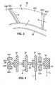
- FIG. 3 is a perspective view of a portion of the sideload vane assembly 50 shown in FIG. 2. Reference markers for angles ⁇ 0 - ⁇ 3 are shown in FIG. 2 in order to better explain angular positioning of various features about the centerline CL.
- the sideload vane assembly 50 is a static component that includes a central opening 52 for the rotor shaft 22 and flange 54 at the perimeter of the assembly having bolt holes for mounting the assembly 50 in the turbopump 20.
- the assembly 50 can be made of a metallic material, such as aluminum.
- a sideload wall 37 is positioned (radially) between the central opening 52 and the flange 54.
- the sideload wall 37 extends circumferentially about the entire assembly 50, that is, the sideload wall 37 has an angular sweep of 360° about the centerline CL.
- the sideload wall 37 is radially positioned so as to align with one of the side of the diffusers 36, 38 or 40 adjacent to one of the corresponding impellers 28, 30 or 32.
- the sideload wall 37 includes a substantially smooth wall portion 58 and six pockets 60A-60F.
- the pockets 60A-60F form five vanes 62A-62E at the circumferentially spaced edges thereof.
- the vanes 62A-62E are located within a first angular region, which has an angular sweep of 154° about the centerline CL between angles ⁇ 1 and ⁇ 3 .
- the vanes 62A-62E are substantially equally angularly spaced within the first angular region.
- the substantially smooth wall portion 58 is located within a second angular region, which has an angular sweep of 205° about the centerline CL between angles ⁇ 3 and ⁇ 1 .
- the first and second angular regions have a combined angular sweep of 360°, that is, together they extend circumferentially about the entire assembly 50.
- the number and arrangement of the vanes can vary. For example, more or fewer than six pockets can be formed.
- the first angular region can have a greater or lesser angular sweep, and the position of the first angular region (i.e., the "rotational" position of the reference markers with respect to a pump mounting location) can vary.
- the vanes need not be equally angularly spaced.
- FIG. 3 a portion of the sideload wall 37 is shown, including pockets 60B-60D and vanes 62C-62D.
- a number of reference dimensions are indicated in FIG. 3, including a vane height H, a vane width W, and a pocket depth D.
- the dimensions H, W, and D can be adjusted for particular applications, to provide desired performance characteristics, including desired radial loading.
- Each of the vanes 62A-62E has a substantially rectangular shape, and the pockets 60A-60F and vanes 62A-62E can be formed by milling the sideload wall 37. Use of rectangular vanes simplifies manufacture while still providing sufficient structural integrity. In alternative embodiments, the shape of the vanes can vary as desired.
- the sideload vane assembly 50 interacts with the fluid in the secondary flowpath (i.e., in the gap between the sideload vane assembly 50 and the adjacent second impeller 30).
- the vanes 62A-62E of the assembly 50 act like asymmetric swirl brakes and generate a non-uniform circumferential pressure field in fluid in the secondary flowpath.
- the non-uniform circumferential pressure field imparts a moment on the adjacent second impeller 30, and that moment produces a radial force component in the second impeller 30 that, in turn, radially loads the rotor shaft 22 and the first bearing set 24.
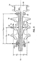
- FIG. 4 is a simplified schematic cross-sectional view of a portion of the turbopump 20, showing a net moment M on the second impeller 30 due to a non-uniform circumferential pressure field generated in conjunction with an adjacent sideload vane assembly 50 (not shown).
- the moment M is shown in FIG. 4 with a generally axial orientation at a location radially spaced from the rotor shaft 22 (and its centerline CL).
- the magnitude and location of the moment M will vary according to the characteristics of particular applications.
- the moment M in turn, produces radial loading in a first direction (at an angle ⁇ 4 , not shown) on the rotor shaft 22 and the first bearing set 24 (and/or the second bearing set 26) as force is transmitted through the impeller 30 and the rotor shaft 22.
- the second bearing set 26 acts like as a fulcrum, while the first bearing set 24 has some freedom of radial movement with respect to a pump housing or ground 20A. This is because the configuration of the turbopump 20 provides sufficient stiffness to the second bearing set 26 to keep it engaged. It should be recognized that the particular characteristics of the bearing sets 24 and 26 will vary depending on the particular configuration of the turbopump 20 and its housing 20A.
- a vector I L represents natural radial loading of the third impeller 32
- a vector T L represents natural radial loading of the turbine assembly 34.
- Vector I L is oriented at about 0-50° with respect to a given angular reference point ⁇ 5 (not shown), and vector T L is oriented at about 0° with respect to the reference point ⁇ 5 .
- the vectors I L and T L arise due to the rotation of and interaction with fluids by the third impeller 32 and the turbine assembly 34, and due to configurations of fluid inlets and outlets of the turbopump 20.
- Vectors I L and T L establish a preferred direction of radial loading for the turbopump 20, based on the natural characteristics of the turbopump 20, that is, based on factors substantially independent from radial loading imparted by the sideload vane assembly 50.
- the vectors I L and T L generally have small magnitudes that, alone, do not provide significant stiffness to the first bearing set 24.
- the sideload vane assembly 50 is configured such that the first direction of radial loading imparted by assembly 50 substantially aligns with the preferred direction of radial loading of the turbopump 20 (i.e., such that ⁇ 4 ⁇ ⁇ 5 ). Such alignment, although not strictly necessary, improves the effectiveness of the radial loading and reduces performance losses.
- FIG. 5 is a free body diagram of the rotatable components of the turbopump 20, showing the impellers 28, 30, 32, the shaft 22, and a portion of the turbine assembly 34 in a schematic cross-sectional form.
- a number of reference markings for vectors, distances, etc. are indicated in FIG. 5 to illustrate some of the parameters that influence loading on components of the turbopump 20 during operation. The definitions of these reference markings are given in Table 1. TABLE 1.
- a 2 Vector for axial load on the selected impeller associated with the second angular region (of the adjacent sideload vane assembly) CL Turbopump centerline axis aligned at the center of the rotor shaft D
- D ATOT Axial distance between the first bearing set and the second bearing set (measured midpoint-to-midpoint)
- R Radial distance between the selected impeller and CL (measured midpoint to midpoint)
- R 1 Vector for radial load on the selected impeller at the first angular region R 2 Vector for radial load on the selected impeller at the second angular region, with vector R 2 being positioned 180° from vector R 1 FBNL Vector for the net radial load on the first bearing set SBNL Vector for the net radial load on the second bearing set
- FBNL 1 - D A D ATOT ⁇ R 1 + D A D ATOT - 1 ⁇ R 2 + A 2 - A 1 ⁇ D R D ATOT
- the vector FBNL for the sideload vane assembly 50 of FIG. 2 is directed at an angle designated as ⁇ 4 , which can be determined empirically.
- the angle ⁇ 4 generally lies within the first angular region of the vane assembly 50, and is generally offset from the symmetry line of the first angular region (i.e., angle ⁇ 2 ) in a direction opposite to the direction of rotation of the impellers 28, 30, 32 and rotor shaft 22.
- the offset of angle ⁇ 4 from angle ⁇ 2 is due to the fluid dynamics within the pump.
- SBNL D R D ATOT ⁇ A 1 - A 2 + D A D ATOT ⁇ R 1 - R 2
- Equations (1) and (2), and the free body diagram in FIG. 5 help illustrate the relationship of the forces that produce radial loading on the first bearing set 24 due to the non-uniform circumferential pressure field created by the sideload vane assembly 50.
- a bench test experiment was performed on an embodiment of the vane assembly 50 like that described above.
- the turbopump 20 was run under normal operating conditions pumping water.
- the sideload vane assembly 50 had five vanes 62A-62E and six pockets 60A-60F, where the vane length L was 3.429 cm (1.35 inches), the vane width W was 0.635 cm (0.250 inches), the pocket depth D was 0.1524 cm (0.060 inches).
- the vanes 62A-62E were equally circumferentially spaced within a first angular region having an angular sweep of about 154°.
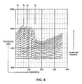
- FIG. 6 is a graph of fluid pressure versus angular location calculated for a number of radial locations in the secondary flowpath of the turbopump 20.
- ⁇ represents the angular location about the turbopump centerline CL in degrees (measured 0-360° from an arbitrarily selected reference point).
- pressure in pounds per square inch (psi) represents the measured static fluid pressure.
- a number of plots are shown on the graph of FIG. 6 each based on pressures at different radial locations from the centerline CL (with the greater radii corresponding to greater average pressures in the fluid).
- the first angular region of the sideload vane assembly 50 corresponds approximately to values of ⁇ between ⁇ 1 and ⁇ 3 (inclusive of ⁇ 2 ), as shown in the graph of FIG. 6.
- the second angular region of the sideload vane assembly 50 corresponds roughly to values of ⁇ between ⁇ 1 and ⁇ 3 (exclusive of ⁇ 2 ) on the graph.
- the graph shows acute pressure rises that generally correspond to when the fluid passed each of the vanes 62A-62E in the first angular region, with the pressure rise being greatest at locations further from the centerline CL. At the smallest radii, nearest the centerline CL, the effects of the vanes 62A-62E is less pronounced.
- the magnitude of FBNL (i.e., the net radial load on the first bearing set 24) was 185.519 kg (409 Ibs.), and that value was obtained by integrating the area under the plots of the graph of FIG. 6.
- a sideload vane assembly according to the present invention can have a variety of vane and pocket configurations.
- a fluid pump can utilize one or more sideload vane assemblies according to the present invention in a variety of locations.
- sideload vane assemblies according to the present invention can be used to reduce the net radial loads on components (e.g., bearings) of a fluid pump, as desired, by configuring the sideload vane assemblies to produce radial loads in opposition to existing radial loads.
Landscapes
- Engineering & Computer Science (AREA)
- Mechanical Engineering (AREA)
- General Engineering & Computer Science (AREA)
- Structures Of Non-Positive Displacement Pumps (AREA)
- Rotary Pumps (AREA)
Abstract
Description
- The present invention relates to vane assemblies suitable for use in fluid pumps, and more particularly to static vane assemblies for producing radial loads on turbopump components.
- Rocket engines can utilize turbopumps to deliver propellants to an injector assembly in the combustion chamber. Such turbopumps have rotors that rotate as the turbopump operates, and impellers that rotate as part of the rotor to increase the pressure of propellants or propellant mixtures. It is desired to obtain a low, steady synchronous vibration response during turbopump operation. However, for a variety of reasons, a particular turbopump may produce an undesired sub-synchronous response. Sub-synchronous vibration responses can be caused, at least in part, by insufficient radial loading on a given bearing set of the turbopump.
- Undesired asynchronous vibration response issues could be addressed in a number of ways. However, many potential solutions are overly complex, insufficiently robust, or are otherwise undesirable, for instance, resulting in an unsatisfactory turbopump performance loss. As one example, the rotor bearings could be redesigned, but redesigns of rotor bearings are difficult and complex. Moreover, flow inlets and outlets create load vectors that could be optimized relative to undesired vibrations, but optimal inlet and outlet flow paths may undesirably increase engine size and/or mass and may provide optimal design "windows" (i.e., tolerances on desired vibration characteristics) that are too small to be practical.
- A fluid pump assembly according to one aspect of the present invention includes a rotatable component that can be rotated about an axis and a static vane assembly located adjacent to the rotatable component. The static vane assembly includes a circumferential surface axially spaced from the rotatable component, and one or more vanes extending from the circumferential surface toward the rotatable component. The one or more vanes are configured to produce a radial load on the rotatable component when the rotatable component is rotating about the axis and a fluid is present between the static vane assembly and the rotatable component.
-
- FIG. 1 is a schematic cross-sectional view of a turbopump.
- FIG. 2 is front view of a sideload vane assembly according to the present invention.
- FIG. 3 is a perspective view of a portion of the sideload vane assembly of FIG. 2.
- FIG. 4 is a simplified schematic cross-sectional view of a portion of the turbopump of FIG. 1 that is radially loaded.
- FIG. 5 is a schematic cross-sectional view of a portion of the turbopump of FIG. 1.
- FIG. 6 is a graph of fluid pressure versus angular location calculated for a number of radial locations in a secondary flowpath of a turbopump.
- The present invention provides an apparatus and method for reducing undesired vibration of components of a fluid pump. In particular, the present invention provides advantages in producing radial loading on bearing supports for pump rotors, which otherwise permit undesired vibrations in an unloaded condition. The present invention utilizes sideload vanes positioned adjacent to rotating members that work upon the fluid in the pump. The sideload vanes produce a non-uniform circumferential pressure field in a fluid in the pump, as fluid moves in a flowpath adjacent to the vanes. The non-uniform circumferential pressure field in turn, imparts radial loading to rotor bearings that otherwise would be substantially unloaded and prone to undesirable vibration issues.
- FIG. 1 is a schematic cross-sectional view of a
turbopump 20 that includes arotor shaft 22 located at a centerline CL, afirst bearing set 24, asecond bearing set 26, and threeimpellers turbine assembly 34 is mechanically connected to therotor shaft 22. The first bearingset 24 is a ball bearing set that includes anouter race 24A and aninner race 24B. Theinner race 24B rotates with therotor shaft 22, while theouter race 24A is static. As used herein, the term "static" refers to being stationary relative to a pump mounting location, and applies even where the entire pump or turbopump has a mounting location in a moving vehicle (or on another movable object). The second bearingset 26 is a roller bearing set. The first andsecond bearing sets turbopump 20. Theimpellers rotor shaft 22 are rotating components when theturbopump 20 is operational. Theimpellers rotor shaft 22, which is driven by rotation of theturbine assembly 34. In operation, a fluid is pumped sequentially through theimpellers impellers turbopump 20 along a primary flowpath, a portion of which is indicated schematically in FIG. 1. Those skilled in the art will recognize that the primary flowpath has a complex shape defined by the rotatingimpellers - A
sideload portion 35 of afirst diffuser 36 is located adjacent to thefirst impeller 28, asideload portion 37 of a second diffuser 38 (also called the 1-2 diffuser) is located adjacent to thesecond impeller 30, and asideload portion 39 of a third diffuser 40 (also called the 2-3 diffuser) is located adjacent to thethird impeller 32. Thediffusers adjacent impellers impellers sideload portion 37 of thesecond diffuser 38 and thesecond impeller 30. The secondary flowpath corresponds to a fluid flow that is generally outside the primary flowpath that carries the majority of fluid through theturbopump 20. In a conventional prior art turbopump, the secondary flowpaths between thesideload portions diffusers impellers rotor shaft 22 or first bearingset 24. - The
turbopump 20 includes numerous other components not specifically identified herein. Those skilled in the art will understand the basic operation of turbopumps. Therefore, further explanation here is unnecessary. - FIGS. 2 and 3 illustrate one embodiment of a
sideload vane assembly 50, which is positioned at the second diffuser 38 (see FIG. 1). It should be recognized that thesideload vane assembly 50 could be positioned adjacent to any of theimpellers turbopump 20 in alternative embodiments. FIG. 2 is front (axial) view of the sideload vane assembly 50 (viewed from thesecond impeller 30 toward the first impeller 28), and FIG. 3 is a perspective view of a portion of thesideload vane assembly 50 shown in FIG. 2. Reference markers for angles ⊖0-⊖3 are shown in FIG. 2 in order to better explain angular positioning of various features about the centerline CL. - The
sideload vane assembly 50 is a static component that includes acentral opening 52 for therotor shaft 22 andflange 54 at the perimeter of the assembly having bolt holes for mounting theassembly 50 in theturbopump 20. Theassembly 50 can be made of a metallic material, such as aluminum. Asideload wall 37 is positioned (radially) between thecentral opening 52 and theflange 54. Thesideload wall 37 extends circumferentially about theentire assembly 50, that is, thesideload wall 37 has an angular sweep of 360° about the centerline CL. Thesideload wall 37 is radially positioned so as to align with one of the side of thediffusers corresponding impellers - The
sideload wall 37 includes a substantiallysmooth wall portion 58 and sixpockets 60A-60F. Thepockets 60A-60F form five vanes 62A-62E at the circumferentially spaced edges thereof. As shown in FIG. 2, the vanes 62A-62E are located within a first angular region, which has an angular sweep of 154° about the centerline CL between angles ⊖1 and ⊖3. The vanes 62A-62E are substantially equally angularly spaced within the first angular region. The substantiallysmooth wall portion 58 is located within a second angular region, which has an angular sweep of 205° about the centerline CL between angles ⊖3 and ⊖1. The first and second angular regions have a combined angular sweep of 360°, that is, together they extend circumferentially about theentire assembly 50. It should be noted that in alternative embodiments, the number and arrangement of the vanes can vary. For example, more or fewer than six pockets can be formed. Moreover, the first angular region can have a greater or lesser angular sweep, and the position of the first angular region (i.e., the "rotational" position of the reference markers with respect to a pump mounting location) can vary. Furthermore, the vanes need not be equally angularly spaced. - In FIG. 3, a portion of the
sideload wall 37 is shown, includingpockets 60B-60D andvanes 62C-62D. A number of reference dimensions are indicated in FIG. 3, including a vane height H, a vane width W, and a pocket depth D. The dimensions H, W, and D can be adjusted for particular applications, to provide desired performance characteristics, including desired radial loading. - Each of the vanes 62A-62E has a substantially rectangular shape, and the
pockets 60A-60F and vanes 62A-62E can be formed by milling thesideload wall 37. Use of rectangular vanes simplifies manufacture while still providing sufficient structural integrity. In alternative embodiments, the shape of the vanes can vary as desired. - In operation, as fluid is being pumped through the
turbopump 20, thesideload vane assembly 50 interacts with the fluid in the secondary flowpath (i.e., in the gap between the sideloadvane assembly 50 and the adjacent second impeller 30). The vanes 62A-62E of theassembly 50 act like asymmetric swirl brakes and generate a non-uniform circumferential pressure field in fluid in the secondary flowpath. The non-uniform circumferential pressure field imparts a moment on the adjacentsecond impeller 30, and that moment produces a radial force component in thesecond impeller 30 that, in turn, radially loads therotor shaft 22 and the first bearing set 24. - FIG. 4 is a simplified schematic cross-sectional view of a portion of the
turbopump 20, showing a net moment M on thesecond impeller 30 due to a non-uniform circumferential pressure field generated in conjunction with an adjacent sideload vane assembly 50 (not shown). The moment M is shown in FIG. 4 with a generally axial orientation at a location radially spaced from the rotor shaft 22 (and its centerline CL). The magnitude and location of the moment M will vary according to the characteristics of particular applications. As explained below, the moment M, in turn, produces radial loading in a first direction (at an angle ⊖4, not shown) on therotor shaft 22 and the first bearing set 24 (and/or the second bearing set 26) as force is transmitted through theimpeller 30 and therotor shaft 22. As shown in FIG. 4, the second bearing set 26 acts like as a fulcrum, while the first bearing set 24 has some freedom of radial movement with respect to a pump housing orground 20A. This is because the configuration of theturbopump 20 provides sufficient stiffness to the second bearing set 26 to keep it engaged. It should be recognized that the particular characteristics of the bearing sets 24 and 26 will vary depending on the particular configuration of theturbopump 20 and itshousing 20A. - A vector IL represents natural radial loading of the
third impeller 32, and a vector TL represents natural radial loading of theturbine assembly 34. Vector IL is oriented at about 0-50° with respect to a given angular reference point ⊖5 (not shown), and vector TL is oriented at about 0° with respect to the reference point ⊖5. The vectors IL and TL arise due to the rotation of and interaction with fluids by thethird impeller 32 and theturbine assembly 34, and due to configurations of fluid inlets and outlets of theturbopump 20. Vectors IL and TL establish a preferred direction of radial loading for theturbopump 20, based on the natural characteristics of theturbopump 20, that is, based on factors substantially independent from radial loading imparted by thesideload vane assembly 50. The vectors IL and TL generally have small magnitudes that, alone, do not provide significant stiffness to the first bearing set 24. - The
sideload vane assembly 50 is configured such that the first direction of radial loading imparted byassembly 50 substantially aligns with the preferred direction of radial loading of the turbopump 20 (i.e., such that ⊖4 ≈ ⊖5). Such alignment, although not strictly necessary, improves the effectiveness of the radial loading and reduces performance losses. - FIG. 5 is a free body diagram of the rotatable components of the
turbopump 20, showing theimpellers shaft 22, and a portion of theturbine assembly 34 in a schematic cross-sectional form. A number of reference markings for vectors, distances, etc. are indicated in FIG. 5 to illustrate some of the parameters that influence loading on components of theturbopump 20 during operation. The definitions of these reference markings are given in Table 1.TABLE 1. Reference Marking Definition A1 Vector for axial load on the selected impeller associated with the first angular region (of the adjacent sideload vane assembly) A2 Vector for axial load on the selected impeller associated with the second angular region (of the adjacent sideload vane assembly) CL Turbopump centerline axis aligned at the center of the rotor shaft DA Axial distance between the selected impeller and the first bearing set (measured midpoint-to-midpoint) DATOT Axial distance between the first bearing set and the second bearing set (measured midpoint-to-midpoint) DR Radial distance between the selected impeller and CL (measured midpoint to midpoint) R1 Vector for radial load on the selected impeller at the first angular region R2 Vector for radial load on the selected impeller at the second angular region, with vector R2 being positioned 180° from vector R1 FBNL Vector for the net radial load on the first bearing set SBNL Vector for the net radial load on the second bearing set - It should be noted that although reference markings are shown in FIG. 5 primarily with respect to the
second impeller 30, similar parameters would exist for theother impellers other impellers - The magnitude for the vector FBNL (i.e., the net radial load on the first bearing set 24) is given by the following equation:

- The vector FBNL for the
sideload vane assembly 50 of FIG. 2 is directed at an angle designated as ⊖4, which can be determined empirically. The angle ⊖4 generally lies within the first angular region of thevane assembly 50, and is generally offset from the symmetry line of the first angular region (i.e., angle ⊖2) in a direction opposite to the direction of rotation of theimpellers rotor shaft 22. The offset of angle ⊖4 from angle ⊖2 is due to the fluid dynamics within the pump. - The magnitude for the vector SBNL (i.e., the net radial load on the second bearing set 26) is given by the following equation:

- The vector FBNL gives the anticipated radial loading on the first bearing set 24, and the
sideload vane assembly 50 can be configured such that the anticipated radial loading provides desired stiffness to maintain engagement of the first bearing set 24 (e.g., to maintain engagement of the first bearing set 24 with thehousing 24A). Equations (1) and (2), and the free body diagram in FIG. 5 help illustrate the relationship of the forces that produce radial loading on the first bearing set 24 due to the non-uniform circumferential pressure field created by thesideload vane assembly 50. - A bench test experiment was performed on an embodiment of the
vane assembly 50 like that described above. Theturbopump 20 was run under normal operating conditions pumping water. Thesideload vane assembly 50 had five vanes 62A-62E and sixpockets 60A-60F, where the vane length L was 3.429 cm (1.35 inches), the vane width W was 0.635 cm (0.250 inches), the pocket depth D was 0.1524 cm (0.060 inches). The vanes 62A-62E were equally circumferentially spaced within a first angular region having an angular sweep of about 154°. - FIG. 6 is a graph of fluid pressure versus angular location calculated for a number of radial locations in the secondary flowpath of the
turbopump 20. On the X-axis, ⊖ represents the angular location about the turbopump centerline CL in degrees (measured 0-360° from an arbitrarily selected reference point). On the Y-axis, pressure in pounds per square inch (psi) represents the measured static fluid pressure. A number of plots are shown on the graph of FIG. 6 each based on pressures at different radial locations from the centerline CL (with the greater radii corresponding to greater average pressures in the fluid). - The first angular region of the
sideload vane assembly 50 corresponds approximately to values of ⊖ between ⊖1 and ⊖3 (inclusive of ⊖2), as shown in the graph of FIG. 6. The second angular region of thesideload vane assembly 50 corresponds roughly to values of ⊖ between ⊖1 and ⊖3 (exclusive of ⊖2) on the graph. The graph shows acute pressure rises that generally correspond to when the fluid passed each of the vanes 62A-62E in the first angular region, with the pressure rise being greatest at locations further from the centerline CL. At the smallest radii, nearest the centerline CL, the effects of the vanes 62A-62E is less pronounced. However, because of radial fluid movement during operation of theturbopump 20, causing fluid to move away from the vanes 62A-62E, the number of acute rises in fluid pressure did not strictly correspond to the number of vanes (five). The angle of radial loading ⊖4 in the present example was approximately 60° with respect to the arbitrarily selected reference point shown on FIG 6. ⊖4 can be calculated according to the following equation, where P is the pressure, r is a variable for the radial location and ⊖ is the variable in the horizontal axis of FIG. 6:
- The magnitude of FBNL (i.e., the net radial load on the first bearing set 24) was 185.519 kg (409 Ibs.), and that value was obtained by integrating the area under the plots of the graph of FIG. 6.
- Although the present invention has been described with reference to preferred embodiments, workers skilled in the art will recognize that changes may be made in form and detail without departing from the scope of the invention. For instance, a sideload vane assembly according to the present invention can have a variety of vane and pocket configurations. Moreover, a fluid pump can utilize one or more sideload vane assemblies according to the present invention in a variety of locations. In addition, sideload vane assemblies according to the present invention can be used to reduce the net radial loads on components (e.g., bearings) of a fluid pump, as desired, by configuring the sideload vane assemblies to produce radial loads in opposition to existing radial loads.
Claims (15)
- A fluid pump assembly (20) comprising:a rotatable component (30) that can be rotated about an axis; anda static vane assembly (50) located adjacent to the rotatable component (30), the static vane assembly comprising:a circumferential surface (37) axially spaced from the rotatable component (30); andone or more vanes (62) extending from the circumferential surface toward the rotatable component, the one or more vanes configured to produce a radial load on the rotatable component when the rotatable component is rotating about the axis and a fluid is present between the static vane assembly and the rotatable component.
- The fluid pump assembly of claim 1, wherein the rotatable component is an impeller assembly (30) mounted on a rotor (22).
- The fluid pump assembly of claim 2, wherein the one or more vanes (62) are configured to produce a radial load on the rotor (22) in a preferred radial direction of movement of the rotor.
- The fluid pump assembly of any preceding claim, wherein the static vane assembly (50) comprises a plurality of circumferentially spaced vanes (62).
- The fluid pump assembly of claim 4, wherein the circumferential surface comprises a first angular region and a second angular region, the first and second angular regions defined perpendicular to the axis of the rotatable component (30) and having a combined angular sweep totaling 360°, and wherein the plurality of circumferentially spaced vanes (62) are all located within the first angular region:
- The fluid pump assembly of claim 5, wherein the plurality of circumferentially spaced vanes (62) are substantially equally angularly spaced within the first angular region.
- The fluid pump assembly of claim 6, wherein the static vane assembly comprises five vanes (62A - 62F) substantially equally angularly spaced with the first angular region, and wherein the first angular region has a sweep of about 154°.
- The fluid pump assembly of any preceding claim, wherein one or more of the vanes (62) is substantially rectangularly shaped.
- The fluid pump assembly of any preceding claim, wherein the circumferential surface (37) defines a case wall.
- A turbopump assembly comprising:a rotor (22) defining an axis of rotation;an impeller assembly (30) supported on the rotor (22) for rotation therewith;a case structure (50) adjacent to the impeller assembly (30) and having one or more vanes (62) extending therefrom; anda secondary flowpath for a fluid medium, the secondary flowpath defined between the impeller assembly (30) and the case structure (50), wherein rotation of the impeller assembly generates a non-uniform circumferential pressure field in the secondary flowpath that produces radial loading on the rotor.
- The turbopump assembly of claim 10, wherein the one or more vanes (62) are configured to generate the non-uniform circumferential pressure field such that the radial load on the rotor (22) is produced in a direction aligned with a preferred radial direction of movement of the rotor.
- The turbopump assembly of claim 10 or 11, wherein one or more of the vanes (62) is substantially rectangularly shaped.
- The turbopump assembly of claim 10, 11 or 12 wherein the one or more vanes (62) are arranged within a first region of the case structure, and wherein the one or more vanes (62) are substantially equally circumferentially spaces within the first region.
- The turbopump assembly of any of claims 10 to 13 and further comprising:a rotor bearing (26) for supporting the rotor (22), wherein the radial loading on the rotor in turn causes radial loading of the rotor against the rotor bearing.
- A method of modifying a turbopump assembly to reduce vibrations, the turbopump assembly including a rotor (22) defining an axis of rotation, an impeller subassembly (30) and a static case (50), the method comprising:identifying a preferred direction of movement of the rotor;determining a non-uniform circumferential pressure field that can be formed in a secondary flowpath between the impeller subassembly (30) and the static case (50) to produce a radial load in the preferred direction of movement of the rotor; andforming vane structures (62) that extend from the case in a pattern that facilitates generation of the non-uniform circumferential pressure field.
Applications Claiming Priority (1)
| Application Number | Priority Date | Filing Date | Title |
|---|---|---|---|
| US11/485,830 US7670110B2 (en) | 2006-07-13 | 2006-07-13 | Sideload vanes for fluid pump |
Publications (2)
| Publication Number | Publication Date |
|---|---|
| EP1878924A2 true EP1878924A2 (en) | 2008-01-16 |
| EP1878924A3 EP1878924A3 (en) | 2011-03-16 |
Family
ID=38222344
Family Applications (1)
| Application Number | Title | Priority Date | Filing Date |
|---|---|---|---|
| EP07251952A Withdrawn EP1878924A3 (en) | 2006-07-13 | 2007-05-11 | Sideload vanes for fluid pump |
Country Status (3)
| Country | Link |
|---|---|
| US (1) | US7670110B2 (en) |
| EP (1) | EP1878924A3 (en) |
| JP (1) | JP5024607B2 (en) |
Cited By (1)
| Publication number | Priority date | Publication date | Assignee | Title |
|---|---|---|---|---|
| CN101832282A (en) * | 2010-04-29 | 2010-09-15 | 中国船舶重工集团公司第七一二研究所 | Low-vibration ventilation fan |
Families Citing this family (5)
| Publication number | Priority date | Publication date | Assignee | Title |
|---|---|---|---|---|
| US8864441B1 (en) * | 2011-05-24 | 2014-10-21 | Florida Turbine Technologies, Inc. | Rocket engine turbopump |
| US20130022473A1 (en) * | 2011-07-22 | 2013-01-24 | Ken Tran | Blades with decreasing exit flow angle |
| WO2014004628A2 (en) * | 2012-06-27 | 2014-01-03 | Flowserve Management Company | Anti-swirl device |
| EP3426925B1 (en) * | 2016-03-08 | 2021-09-08 | Fluid Handling LLC. | Center bushing to balance axial forces in multi-stage pumps |
| JP7558083B2 (en) * | 2021-02-25 | 2024-09-30 | 三菱重工コンプレッサ株式会社 | Compressor |
Citations (1)
| Publication number | Priority date | Publication date | Assignee | Title |
|---|---|---|---|---|
| SU830007A1 (en) | 1979-07-25 | 1981-05-15 | Предприятие П/Я А-7569 | Centrifugal pump |
Family Cites Families (8)
| Publication number | Priority date | Publication date | Assignee | Title |
|---|---|---|---|---|
| CH655357A5 (en) * | 1981-09-28 | 1986-04-15 | Sulzer Ag | Method and device for reducing the axial thrust in turbo machines |
| US4983051A (en) | 1988-05-12 | 1991-01-08 | United Technologies Corporation | Apparatus for supporting a rotating shaft in a rotary machine |
| US5320482A (en) * | 1992-09-21 | 1994-06-14 | The United States Of America As Represented By The Secretary Of The Navy | Method and apparatus for reducing axial thrust in centrifugal pumps |
| DE4435192C1 (en) * | 1994-09-30 | 1996-02-29 | Klein Schanzlin & Becker Ag | Centrifugal pump impeller for contaminated liquids |
| US6053636A (en) | 1998-11-10 | 2000-04-25 | United Technologies Corporation | Hydrostatic bearing with compensatory fluid injection |
| JP2000199520A (en) * | 1999-01-06 | 2000-07-18 | Konica Corp | Rotary device |
| JP4089209B2 (en) * | 2001-11-15 | 2008-05-28 | 株式会社日立プラントテクノロジー | Double suction centrifugal pump |
| JP2003322098A (en) * | 2002-02-26 | 2003-11-14 | Hitachi Ltd | Single-shaft multi-stage pump |
-
2006
- 2006-07-13 US US11/485,830 patent/US7670110B2/en not_active Expired - Fee Related
-
2007
- 2007-05-08 JP JP2007122936A patent/JP5024607B2/en not_active Expired - Fee Related
- 2007-05-11 EP EP07251952A patent/EP1878924A3/en not_active Withdrawn
Patent Citations (1)
| Publication number | Priority date | Publication date | Assignee | Title |
|---|---|---|---|---|
| SU830007A1 (en) | 1979-07-25 | 1981-05-15 | Предприятие П/Я А-7569 | Centrifugal pump |
Cited By (1)
| Publication number | Priority date | Publication date | Assignee | Title |
|---|---|---|---|---|
| CN101832282A (en) * | 2010-04-29 | 2010-09-15 | 中国船舶重工集团公司第七一二研究所 | Low-vibration ventilation fan |
Also Published As
| Publication number | Publication date |
|---|---|
| US20080014081A1 (en) | 2008-01-17 |
| EP1878924A3 (en) | 2011-03-16 |
| JP2008019855A (en) | 2008-01-31 |
| JP5024607B2 (en) | 2012-09-12 |
| US7670110B2 (en) | 2010-03-02 |
Similar Documents
| Publication | Publication Date | Title |
|---|---|---|
| EP1878924A2 (en) | Sideload vanes for fluid pump | |
| JP7667895B2 (en) | Turbomachinery | |
| EP1957800B1 (en) | Impeller for a centrifugal compressor | |
| EP1926915B1 (en) | Stationary seal ring for a centrifugal compressor | |
| EP1937979B1 (en) | Centrifugal compressor including a seal system | |
| CA2786040C (en) | Gas turbine engine and high speed rolling element bearing system | |
| US10982547B2 (en) | Compressor having reinforcing disk, and gas turbine having same | |
| US20070110595A1 (en) | Fluid conveying machine | |
| US9004857B2 (en) | Barrel-shaped centrifugal compressor | |
| JPH0324561B2 (en) | ||
| US12480530B2 (en) | Centrifugal acceleration stabilizer | |
| US6474938B2 (en) | Fuel pump for gas turbines | |
| EP4483062B1 (en) | A multi-stage centrifugal pump comprising an assembly for compensating axial forces | |
| CN115199403B (en) | Gas turbine | |
| Erler et al. | Sideload vanes for fluid pump | |
| Ivanovich et al. | Study of impeller design parameters effect on the axial thrust of a centrifugal electric pump assembly | |
| US20250305539A1 (en) | Foil bearing assembly including bidirectional anti-rotation features and compressor including same | |
| KR101473425B1 (en) | turbo compressor comprising impeller with inlet hole | |
| KR20010081645A (en) | Structure for reducing gas reakage of turbo compressor | |
| JPH0583339U (en) | Gas turbine engine |
Legal Events
| Date | Code | Title | Description |
|---|---|---|---|
| PUAI | Public reference made under article 153(3) epc to a published international application that has entered the european phase |
Free format text: ORIGINAL CODE: 0009012 |
|
| AK | Designated contracting states |
Kind code of ref document: A2 Designated state(s): AT BE BG CH CY CZ DE DK EE ES FI FR GB GR HU IE IS IT LI LT LU LV MC MT NL PL PT RO SE SI SK TR |
|
| AX | Request for extension of the european patent |
Extension state: AL BA HR MK YU |
|
| PUAL | Search report despatched |
Free format text: ORIGINAL CODE: 0009013 |
|
| AK | Designated contracting states |
Kind code of ref document: A3 Designated state(s): AT BE BG CH CY CZ DE DK EE ES FI FR GB GR HU IE IS IT LI LT LU LV MC MT NL PL PT RO SE SI SK TR |
|
| AX | Request for extension of the european patent |
Extension state: AL BA HR MK RS |
|
| 17P | Request for examination filed |
Effective date: 20110914 |
|
| AKX | Designation fees paid |
Designated state(s): DE GB |
|
| STAA | Information on the status of an ep patent application or granted ep patent |
Free format text: STATUS: THE APPLICATION HAS BEEN WITHDRAWN |
|
| 18W | Application withdrawn |
Effective date: 20140908 |