EP1878388A1 - Ultrasonic probe with a device for removing bubbles - Google Patents
Ultrasonic probe with a device for removing bubbles Download PDFInfo
- Publication number
- EP1878388A1 EP1878388A1 EP07013476A EP07013476A EP1878388A1 EP 1878388 A1 EP1878388 A1 EP 1878388A1 EP 07013476 A EP07013476 A EP 07013476A EP 07013476 A EP07013476 A EP 07013476A EP 1878388 A1 EP1878388 A1 EP 1878388A1
- Authority
- EP
- European Patent Office
- Prior art keywords
- ultrasonic
- housing
- bubbles
- ultrasonic probe
- tube
- Prior art date
- Legal status (The legal status is an assumption and is not a legal conclusion. Google has not performed a legal analysis and makes no representation as to the accuracy of the status listed.)
- Withdrawn
Links
Images




Classifications
-
- A—HUMAN NECESSITIES
- A61—MEDICAL OR VETERINARY SCIENCE; HYGIENE
- A61B—DIAGNOSIS; SURGERY; IDENTIFICATION
- A61B1/00—Instruments for performing medical examinations of the interior of cavities or tubes of the body by visual or photographical inspection, e.g. endoscopes; Illuminating arrangements therefor
- A61B1/12—Instruments for performing medical examinations of the interior of cavities or tubes of the body by visual or photographical inspection, e.g. endoscopes; Illuminating arrangements therefor with cooling or rinsing arrangements
-
- A—HUMAN NECESSITIES
- A61—MEDICAL OR VETERINARY SCIENCE; HYGIENE
- A61B—DIAGNOSIS; SURGERY; IDENTIFICATION
- A61B8/00—Diagnosis using ultrasonic, sonic or infrasonic waves
- A61B8/42—Details of probe positioning or probe attachment to the patient
- A61B8/4272—Details of probe positioning or probe attachment to the patient involving the acoustic interface between the transducer and the tissue
- A61B8/4281—Details of probe positioning or probe attachment to the patient involving the acoustic interface between the transducer and the tissue characterised by sound-transmitting media or devices for coupling the transducer to the tissue
-
- A—HUMAN NECESSITIES
- A61—MEDICAL OR VETERINARY SCIENCE; HYGIENE
- A61B—DIAGNOSIS; SURGERY; IDENTIFICATION
- A61B1/00—Instruments for performing medical examinations of the interior of cavities or tubes of the body by visual or photographical inspection, e.g. endoscopes; Illuminating arrangements therefor
-
- A—HUMAN NECESSITIES
- A61—MEDICAL OR VETERINARY SCIENCE; HYGIENE
- A61B—DIAGNOSIS; SURGERY; IDENTIFICATION
- A61B8/00—Diagnosis using ultrasonic, sonic or infrasonic waves
- A61B8/44—Constructional features of the ultrasonic, sonic or infrasonic diagnostic device
- A61B8/4444—Constructional features of the ultrasonic, sonic or infrasonic diagnostic device related to the probe
- A61B8/4461—Features of the scanning mechanism, e.g. for moving the transducer within the housing of the probe
-
- B—PERFORMING OPERATIONS; TRANSPORTING
- B06—GENERATING OR TRANSMITTING MECHANICAL VIBRATIONS IN GENERAL
- B06B—METHODS OR APPARATUS FOR GENERATING OR TRANSMITTING MECHANICAL VIBRATIONS OF INFRASONIC, SONIC, OR ULTRASONIC FREQUENCY, e.g. FOR PERFORMING MECHANICAL WORK IN GENERAL
- B06B1/00—Methods or apparatus for generating mechanical vibrations of infrasonic, sonic, or ultrasonic frequency
- B06B1/02—Methods or apparatus for generating mechanical vibrations of infrasonic, sonic, or ultrasonic frequency making use of electrical energy
- B06B1/06—Methods or apparatus for generating mechanical vibrations of infrasonic, sonic, or ultrasonic frequency making use of electrical energy operating with piezoelectric effect or with electrostriction
- B06B1/0607—Methods or apparatus for generating mechanical vibrations of infrasonic, sonic, or ultrasonic frequency making use of electrical energy operating with piezoelectric effect or with electrostriction using multiple elements
- B06B1/0622—Methods or apparatus for generating mechanical vibrations of infrasonic, sonic, or ultrasonic frequency making use of electrical energy operating with piezoelectric effect or with electrostriction using multiple elements on one surface
- B06B1/0637—Spherical array
-
- G—PHYSICS
- G01—MEASURING; TESTING
- G01S—RADIO DIRECTION-FINDING; RADIO NAVIGATION; DETERMINING DISTANCE OR VELOCITY BY USE OF RADIO WAVES; LOCATING OR PRESENCE-DETECTING BY USE OF THE REFLECTION OR RERADIATION OF RADIO WAVES; ANALOGOUS ARRANGEMENTS USING OTHER WAVES
- G01S15/00—Systems using the reflection or reradiation of acoustic waves, e.g. sonar systems
- G01S15/88—Sonar systems specially adapted for specific applications
- G01S15/89—Sonar systems specially adapted for specific applications for mapping or imaging
- G01S15/8906—Short-range imaging systems; Acoustic microscope systems using pulse-echo techniques
- G01S15/8934—Short-range imaging systems; Acoustic microscope systems using pulse-echo techniques using a dynamic transducer configuration
- G01S15/8938—Short-range imaging systems; Acoustic microscope systems using pulse-echo techniques using a dynamic transducer configuration using transducers mounted for mechanical movement in two dimensions
- G01S15/894—Short-range imaging systems; Acoustic microscope systems using pulse-echo techniques using a dynamic transducer configuration using transducers mounted for mechanical movement in two dimensions by rotation about a single axis
-
- G—PHYSICS
- G01—MEASURING; TESTING
- G01S—RADIO DIRECTION-FINDING; RADIO NAVIGATION; DETERMINING DISTANCE OR VELOCITY BY USE OF RADIO WAVES; LOCATING OR PRESENCE-DETECTING BY USE OF THE REFLECTION OR RERADIATION OF RADIO WAVES; ANALOGOUS ARRANGEMENTS USING OTHER WAVES
- G01S7/00—Details of systems according to groups G01S13/00, G01S15/00, G01S17/00
- G01S7/52—Details of systems according to groups G01S13/00, G01S15/00, G01S17/00 of systems according to group G01S15/00
- G01S7/52017—Details of systems according to groups G01S13/00, G01S15/00, G01S17/00 of systems according to group G01S15/00 particularly adapted to short-range imaging
- G01S7/52079—Constructional features
-
- A—HUMAN NECESSITIES
- A61—MEDICAL OR VETERINARY SCIENCE; HYGIENE
- A61B—DIAGNOSIS; SURGERY; IDENTIFICATION
- A61B8/00—Diagnosis using ultrasonic, sonic or infrasonic waves
- A61B8/44—Constructional features of the ultrasonic, sonic or infrasonic diagnostic device
- A61B8/4444—Constructional features of the ultrasonic, sonic or infrasonic diagnostic device related to the probe
- A61B8/4455—Features of the external shape of the probe, e.g. ergonomic aspects
-
- G—PHYSICS
- G01—MEASURING; TESTING
- G01S—RADIO DIRECTION-FINDING; RADIO NAVIGATION; DETERMINING DISTANCE OR VELOCITY BY USE OF RADIO WAVES; LOCATING OR PRESENCE-DETECTING BY USE OF THE REFLECTION OR RERADIATION OF RADIO WAVES; ANALOGOUS ARRANGEMENTS USING OTHER WAVES
- G01S15/00—Systems using the reflection or reradiation of acoustic waves, e.g. sonar systems
- G01S15/88—Sonar systems specially adapted for specific applications
- G01S15/89—Sonar systems specially adapted for specific applications for mapping or imaging
- G01S15/8906—Short-range imaging systems; Acoustic microscope systems using pulse-echo techniques
- G01S15/8993—Three dimensional imaging systems
-
- G—PHYSICS
- G10—MUSICAL INSTRUMENTS; ACOUSTICS
- G10K—SOUND-PRODUCING DEVICES; METHODS OR DEVICES FOR PROTECTING AGAINST, OR FOR DAMPING, NOISE OR OTHER ACOUSTIC WAVES IN GENERAL; ACOUSTICS NOT OTHERWISE PROVIDED FOR
- G10K11/00—Methods or devices for transmitting, conducting or directing sound in general; Methods or devices for protecting against, or for damping, noise or other acoustic waves in general
- G10K11/02—Mechanical acoustic impedances; Impedance matching, e.g. by horns; Acoustic resonators
-
- G—PHYSICS
- G10—MUSICAL INSTRUMENTS; ACOUSTICS
- G10K—SOUND-PRODUCING DEVICES; METHODS OR DEVICES FOR PROTECTING AGAINST, OR FOR DAMPING, NOISE OR OTHER ACOUSTIC WAVES IN GENERAL; ACOUSTICS NOT OTHERWISE PROVIDED FOR
- G10K11/00—Methods or devices for transmitting, conducting or directing sound in general; Methods or devices for protecting against, or for damping, noise or other acoustic waves in general
- G10K11/18—Methods or devices for transmitting, conducting or directing sound
- G10K11/26—Sound-focusing or directing, e.g. scanning
- G10K11/35—Sound-focusing or directing, e.g. scanning using mechanical steering of transducers or their beams
- G10K11/352—Sound-focusing or directing, e.g. scanning using mechanical steering of transducers or their beams by moving the transducer
Definitions
- the present invention generally relates to ultrasonic probes, and more particularly to an ultrasonic probe configured to reciprocate an ultrasonic element within a certain range and remove bubbles from liquid provided for propagating ultrasonic waves.
- An ultrasonic diagnostic apparatus is widely used to diagnose a subject by visualizing a portion within the subject's body.
- the ultrasonic diagnostic apparatus has an ultrasonic probe, which is used to make contact with the skin of the subject.
- the ultrasonic probe has an ultrasonic element therein.
- the ultrasonic element serves to generate ultrasonic waves and transmit/receive ultrasonic waves.
- the ultrasonic probe can be classified as a linear, convex or circular type according to an array formation of ultrasonic vibrating elements constructing the ultrasonic element. Further, the ultrasonic probe can be classified as a two-dimensional image probe or a three-dimensional image probe according to the type of obtained images. Recently, an ultrasonic probe, which is configured to reciprocate the ultrasonic element within a certain range, has been used to obtain a more accurate two-dimensional or three-dimensional image.
- Fig. 1 is a partially cutaway front view of a prior art ultrasonic probe for use in acquiring a three-dimensional image.
- the ultrasonic probe 10 includes a case 11, which is sized and configured to be grasped by an operator or user and accommodates various parts therein.
- An ultrasonic element 12 is disposed adjacent to a front end of the case 11.
- the ultrasonic element 12 is connected to a main body of an ultrasonic diagnostic apparatus (not shown) via a cable 16.
- a drive device (not shown), which causes the ultrasonic element 12 to be reciprocated around a shaft 14 within a certain range, is provided inside the case 11.
- a cover 13, which covers and protects the ultrasonic element 12 and may be in contact with the skin of a subject, is joined to the front end of the case 11.
- An enclosed space defined by the cover 13 and the case 11, wherein the ultrasonic element 12 is reciprocated, is filled with oil 15 in order to facilitate the propagation of ultrasonic waves.
- Oil 15 is injected into the enclosed space after said space is established in the ultrasonic probe 10.
- the oil 15 is injected to replace the air in the enclosed space.
- injecting the oil and discharging the air are carried out simultaneously.
- parts such as ultrasonic element 12, bearings and screw threads of the drive device, etc.
- Such parts have a number of concave-convex portions thereon.
- Fig. 1 is a partially cutaway front view of a prior art ultrasonic probe for use in acquiring a three-dimensional image
- Fig. 2 is a partially cutaway perspective view of an ultrasonic probe constructed in accordance with a first embodiment of the present invention
- Fig. 3 is a sectional view showing a device for removing bubbles
- Fig. 4 is a partial sectional view of the ultrasonic probe shown in Fig. 2 when the bubbles are removed;
- Fig. 5 is a view showing a state when the accumulated bubbles are not discharged again
- Fig. 6 is a sectional view showing an alternative to the bubble-removing device shown in Fig. 3;
- Fig. 7 is a sectional view of the bubble-removing device shown in Fig. 6 when the bubbles are not discharged again;
- Fig. 8 is a partially cutaway perspective view of an ultrasonic probe constructed in accordance with a second embodiment of the present invention.
- Fig. 9 is a sectional view of a device for removing bubbles shown in Fig. 8.
- Fig. 10 is a bottom view of a connector of the bubble-removing device shown in Fig. 9.
- frontward and rearward are intended to mean a direction in which an ultrasonic probe is brought into contact with the skin of a subject and an opposite direction thereof, respectively.
- frontward and rearward are intended to mean a direction in which an ultrasonic probe is brought into contact with the skin of a subject and an opposite direction thereof, respectively.
- Fig. 2 is a partially cutaway perspective view of an ultrasonic probe, which is constructed in accordance with a first embodiment of the present invention.
- the ultrasonic probe 100 comprises the following: an ultrasonic element assembly 111; a housing 112 for supporting the ultrasonic element assembly 111 so that the ultrasonic element assembly 111 is reciprocated therein; a cover 113 for covering and protecting the ultrasonic element assembly 111; a case 114 configured to be hand-held by a user and secure the housing 112 and the cover 112 thereto; a drive device 120 mounted to the housing 112 for reciprocating the ultrasonic element assembly 111 within a certain range; and a device for removing bubbles 130.
- Various electrical signals of the ultrasonic probe 100 are transmitted and received to and from a main body of an ultrasonic diagnostic apparatus (not shown) using a cable 118.
- the cable 118 is extended from a rearward portion of the case 114 through a flexible bushing 117.
- the ultrasonic element assembly 111 includes: an ultrasonic element 111a; an element holder 111b for fixing and supporting the ultrasonic element 111a; a rope holder 111c for attaching a wire rope 124 thereto; and a shaft 111d serving as a pivot, around which the ultrasonic element assembly 111 is pivotally reciprocated.
- the ultrasonic element 111a comprises a number of ultrasonic vibrating elements including a piezoelectric material, a backing layer and a matching layer.
- the ultrasonic element 111 a of this embodiment may be formed so as to allow a number of ultrasonic vibrating elements to be curvilinearly arrayed.
- the ultrasonic element 111 a is connected to the main body of the ultrasonic diagnostic apparatus using the cable 118.
- the ultrasonic element generates ultrasonic waves from the signals, which are transmitted from the main body of the ultrasonic diagnostic apparatus, and transmits the same.
- the ultrasonic element may further be configured to receive the reflected ultrasonic waves, convert the received ultrasonic waves into electrical signals and output the electrical signals to the main body of the ultrasonic diagnostic apparatus.
- the element holder 111b supports the ultrasonic element 111a at both sides thereof.
- the shaft 111d is formed at both sides of the element holder 111b.
- the rope holder 111c which is coaxially positioned together with the shaft 111d, is secured to the element holder 111b.
- the shaft 111d is rotatably joined to a shaft-supporting portion 112a formed at a frontward end of the housing 112.
- the housing 112 is opened at its frontward side so that the ultrasonic element assembly 111 is placed therein.
- the housing 112 is closed at its rearward side.
- a portion of the drive device 120 is introduced inside the housing 112 through an extended portion 112b formed at the rearward side of the housing 112.
- the drive device 120 includes the following: an electrical motor 121; a connecting shaft 122, which is connected to a rotating shaft of the electrical motor 121 at its one end and is introduced inside the housing 112 through the extended portion 112b at its other end; a rope-driving pulley 123 coupled to the other end of the connecting shaft 112; and the wire rope 124 hung between the rope-driving pulley 123 and the rope holder 111c.
- the electrical motor 121 receives electrical power required for its operation from the main body of the ultrasonic diagnostic apparatus using the cable 118 while being controlled by the main body of the ultrasonic diagnostic apparatus.
- the normal or reverse rotation of the electrical motor 121 effectuates clockwise or counterclockwise rotational movement of the ultrasonic element assembly 111 around the shaft 111d through the connecting shaft 122, the rope-driving pulley 123, the wire rope 124 and the rope holder 111c. Since the electrical motor 121 effectuates the normal or reverse rotation, the ultrasonic element assembly 111 can be reciprocated accordingly within a certain range.
- the drive device 120 e.g., rope-driving pulley 123 and wire rope 124.
- the housing 112 may be configured to accommodate the entire drive device 120.
- the drive device 120 shown in Fig. 1 reciprocates the ultrasonic element assembly 111 by using the wire rope.
- spur gears, worm gears, racks-pinions, cams or the like may be employed as a driving mechanism of the drive device 120.
- the pivotally reciprocable ultrasonic element assembly 111 cannot be brought into direct contact with the skin of the subject.
- the cover 113 is joined to the frontward edge of the housing 112 for contacting the skin of the subject.
- the cover 113 covers and protects the ultrasonic element assembly 111 while defining an enclosed space 115, wherein the ultrasonic element assembly 111 is reciprocated, together with the housing 112.
- the cover 113 may be formed from a high molecular material similar to a human body so as to possess hardness or elasticity, which is deformable according to a reaction force of the skin of the subject.
- the cover 113 is dome-shaped.
- the cover 113 may be formed to have a flat shape.
- the case 114 which is cylinder-shaped, is joined to the frontward edge of the housing 112 at its opened one end. While the cover 113 is joined to the housing 112 and the case 114 fixes and supports the housing 113 as shown in Fig. 1, the housing 112 may be joined to the case 114 and the cover 113 may be joined to the case 114. Alternatively, the housing 112 may be omitted and the case 114 may secure the drive device 120 and support the ultrasonic element assembly 111 so that it can be reciprocated.
- the enclosed space 115 is filled with air
- ultrasonic waves which are transmitted from and received by the ultrasonic element 111a, are difficult to propagate through air.
- a liquid medium 116 is filled in the enclosed space 115 to facilitate the unobstructed propagation of ultrasonic waves. Oil or saline solution can be used as the liquid medium 116.
- the liquid medium 116 is injected into the housing 112 after the ultrasonic element assembly 111 and the cover 113 are assembled into the housing 112.
- the extended portion 112b of the housing 112 is formed with an injection port 112c for injecting the liquid medium and an exhaust port 112d, through which the air replaced by injection of the liquid medium is exhausted. If the injection of the liquid medium is ended, then the injection port 112c and the exhaust port 112d are sealed up. This accomplishes the enclosed space 115, wherein the ultrasonic element assembly 111 is reciprocated.
- the surfaces of the components located in the enclosed space 115 are not even. Rather, they have various concave-convex portions. Therefore, when the liquid medium is injected, the air in said concave-convex portions remains in the liquid medium to thereby form bubbles. Such bubbles obstruct the propagation of the ultrasonic waves to thereby deteriorate the performance of the ultrasonic probe 100. However, the bubble-removing device 130 removes the bubbles from the liquid medium and accumulates the removed bubbles.
- the bubble-removing device 130 is joined to a rearmost portion (e.g., extended portion 112b) among portions of the housing 112, which are opposed to the cover 113.
- the bubble-removing device 130 comprises a tubular member and a communication portion for allowing the bubbles to pass into the tubular member and restricting a counter passing thereof.
- the tubular member includes a straight tube 131, which is made from plastic or rubber.
- the tube 131 is joined to the extended portion 112b at its one end in such a manner that it penetrates a wall of the extended portion 112b.
- the tube 131 is closed at its other end 134.
- the one end of the tube 131 consists of a connector 133.
- the tube 131 is located in the case 114 so that the other end 134 of the tube 131 is farther away from the cover 113 than the connector 133.
- the communication portion is disposed in the connector 133.
- Fig. 3 is a sectional view of the bubble-removing device 130.
- the connector 133 includes the following: a cylindrical connector body 133a; one end 133b facing the inside of the housing 112; and the other end 133c configured to join a body of the tube 131.
- the one end 133b of the connector is formed at its middle portion with an opening.
- the connector body 133a is liquid-tightly joined to the rearmost portion of the housing (e.g., extended portion 112b) whereby the bubble-removing device 130 is fixed to the rearmost portion of the housing.
- the communication portion 132 which is disposed at the one end of the tube 131 (more specifically, the connector 133), includes the following: a communication passage 132a having a shape of a truncated cone; and an inlet 132b and an outlet 132c formed at both ends of the communication passage 132.
- the communication portion 132 is located in the connector body 133a such that the outlet 132c faces the inside of the tube 131 while the inlet 132b faces the inside of the housing 112.
- the inlet 132b is coupled to the opening formed at the one end 133b of the connector.
- the communication passage 132a becomes narrow as it goes toward the outlet 132c. Therefore, the size of the outlet 132c is smaller than that of the inlet 132b.
- the size of the outlet 132c is determined such that one of the bubbles remaining in the liquid medium can pass through the outlet 132c.
- Fig. 4 is a partially sectional view of the ultrasonic probe 100, which shows that the bubbles are being accumulated within the tube 131.
- Fig. 4 illustrates a state where the ultrasonic probe 100 is placed vertically so that its cover side faces the ground (hereinafter, such a state is referred to as "a bubble-removing state").
- the bubbles 116a float up rearward (toward the side opposite to the cover 113) due to their buoyancies.
- the floating up bubbles 116a reach the vicinity of the inlet 132b of the communication portion.
- the bubbles 116a enter the inlet 132b and gather in the communication passage 132a.
- said bubble 116a moves up along a sloped surface of the communication passage 132a due to its buoyancy and passes through the outlet 132c to enter the inside of the tube 131.
- a number of bubbles enters the communication passage 132a, said bubbles 116a gather in the vicinity of the outlet 132c and then pass through the outlet 132c in order to enter the inside of the tube 131 due to their buoyancies one by one.
- the ultrasonic probe 110 When the ultrasonic probe 110 is left in the bubble-removing state, the bubbles 116a continuously enter the inside of the tube 131 and can be accumulated inside the tube 131 from the vicinity of the other end 134 of the tube 131.
- the ultrasonic probe 100 may be left in the bubble-removing state when the ultrasonic probe 100 is placed for a certain period of time after ending assembly in the state where its cover side faces the ground.
- the ultrasonic probe 100 may be left in the bubble-removing state when ultrasonic diagnosis can be carried out using the ultrasonic probe 100. In both cases, removing and accumulating the bubbles take place as described above.
- the cover 113 is made from an elastic material, if the cover is slightly pressed toward the inside of the ultrasonic probe during the ultrasonic diagnosis, then the bubbles 116a, which gather in the communication passage 132a, are allowed to enter the inside of the tube 131 more easily due to the pressure applied to the liquid medium.
- Fig. 5 shows a state where the accumulated bubbles are not discharged again (contrary to the state shown in Fig. 4).
- the ultrasonic probe 100 may be placed on any fixture (e.g., a probe holder 20 provided on the main body of the ultrasonic diagnostic apparatus).
- the bubbles 116a accumulated within the tube 131 float up along the tube 131 toward the outlet 132c.
- the diameter of the outlet 132c is very narrow, the floating up bubbles 116a are difficult to move through the outlet 132c toward the inlet 132b.
- the floating up bubbles 116a are restricted from being discharged to the inside of the housing through the rearmost portion of the housing by the other end 133c of the connector.
- a very small amount of bubbles, among the accumulated bubbles can enter the inside of the housing 112 through the outlet 132c, such bubbles can be removed from the liquid medium 116 again whenever the ultrasonic probe 100 is in the bubble-removing state. Consequently, the bubbles 116a remaining in the liquid medium 116 are allowed to be accumulated in the tube 131 while being removed successively. Even when the ultrasonic probe 100 is placed horizontally, the bubbles already accumulated in the tube 131 are difficult to be discharged to the housing 112 due to the structure of the bubble-removing device 130.
- Fig. 6 shows an alternative to the bubble-removing device shown in Fig. 3 in the bubble-removing state.
- the tube 131 includes a blocking plate 131a therein.
- the blocking plate 131a is sloped toward the other end 134 and blocks the inside of the tube 131 with a gap, which is sized such that the bubbles can move therethrough.
- a plurality of blocking plates may be included inside the housing 112.
- the communication portion 132' includes a funnel-shaped or a truncated cone-shaped communication passage 132a', which becomes narrow as it proceeds toward the other end 134.
- the connector 133' has a barrel shape to define a cavity 133d together with the communication portion 132'.
- the bubbles 116a move through the outlet 132c and enter the inside of the tube 131. Also, the bubbles move up along the blocking plate 131 a and reach the other end 134 of the tube 131 so as to be accumulated in the tube 131.
- Fig. 7 is a sectional view of the bubble-removing device 130' when the ultrasonic probe is placed in an opposite state to the bubble-removing state.
- Fig. 8 is a partially cutaway perspective view of an ultrasonic probe, which is constructed in accordance with a second embodiment of the present invention.
- the ultrasonic probe 200 of this embodiment has the same configuration as the ultrasonic probe 100 of the first embodiment, except that the bubble-removing device is configured to allow the injection of the liquid medium.
- the bubble-removing device 230 comprises a tubular member and a communication portion (not shown) for permitting the bubbles to pass into the tubular member and restricting a counter passing thereof.
- the tubular member is joined to the rearmost portion (e.g., extended portion 112b) of the housing at its one end in such a manner that it penetrates the wall of the extended portion 112b.
- the other end of the tubular member is closed and configured to allow the injection of the liquid medium.
- the communication portion is disposed at the one end of the tubular member.
- the tubular member includes a tube 231, which is made from a soft material (e.g., rubber) or a hard material (e.g., plastic) and is bent at one portion thereof.
- the tube 231 extends rearward vertically from the rearmost portion 112b of the housing 112 and is bent in the vicinity of the rearward inner wall of the case 114. It further extends along the rearward inner wall of the case 114.
- One end of the tube 231 consists of a connector 233, which is joined to a medium injection port of the rearmost portion of the housing.
- the closed other end 234 of the tube 231 consists of an injection port 234a fitted to the tube 231 and a plug 234b for sealing the injection port 234a.
- the injection port 234a is retained in the inner wall of the case 114 by being engaged to a hook-shaped injection port holder 114a provided on a rearmost portion of the inner wall of the case 114, thereby being located farther away from the cover 112 than the connector 233.
- Fig. 9 is a sectional view of the bubble-removing device 230 shown in Fig. 8.
- Fig. 10 is a bottom view of the connector 233 of the bubble-removing device 230.
- the connector 233 includes the following: a barrel-shaped connector body 233a; one end 233b facing the inside of the housing 112; and the other end 233c to which a body of the tube 231 is coupled.
- the one end 233b is formed with an opening.
- the communication portion 232 which is disposed at the one end of the tube 231 (more specifically, the connector 233), includes the following: a funnel-shaped communication passage 232a, which becomes narrow as it proceeds toward the other end 234; and an inlet 232b and an outlet 232c formed at both ends of the communication passage 232a.
- the inlet 232b is coupled to the opening formed at the one end 233b of the connector.
- the outlet 232c is opened toward the inside of the tube 231.
- the size of the outlet 232c is much smaller than that of the inlet 232b due to the funnel shape of the communication passage 232a.
- the size of the outlet 232c is determined such that one of the bubbles remaining in the liquid medium can pass through the outlet 232c.
- a cavity 233d is formed between the inner wall of the connector body 233a and the communication portion 232 in the connector 233.
- the communication portion 233 further includes a plurality of funnel-shaped through-holes 233e at its one end 233b.
- the through-holes 233e are located adjacent to the inlet 232c.
- the through-hole 233e becomes narrow as it proceeds toward the inside of the connector body 233a.
- the bubble-removing device 230 is joined to the medium injecting port 112e and the injection of the liquid medium is continued.
- the liquid medium is injected into the housing 112 through the outlet 232c of the communication portion and the through-holes 233e.
- the air inside the housing 112 can be discharged through one of the outlets 232c and the through-holes 233e.
- the injection port 234a is plugged with the plug 234b and the injection port 234a is secured to the case 114. Thereafter, the assembly of the ultrasonic probe 200 is continued.
- the bubble-removing device 200 may be used to inject the liquid medium during the assembly of the ultrasonic prove 200 and remove the bubbles remaining in the filled liquid medium after the ultrasonic probe 200 is completely assembled.
- Embodiments of the present invention may provide an ultrasonic probe.
- the ultrasonic probe of the present invention can simply and successively remove the bubbles remaining in the liquid medium filled in the enclosed space, wherein the ultrasonic element is reciprocated.
- the ultrasonic probe is vertically placed so that the cover faces the ground or when the ultrasonic diagnosis is carried out with the ultrasonic probe, the bubbles can be removed from the liquid medium.
- the ultrasonic probe of the present invention may comprise an ultrasonic element, a housing, a drive device, a cover, a liquid medium and a device for removing bubbles.
- the housing may support the ultrasonic element so that the ultrasonic probe can be reciprocated therein.
- the drive device may be secured to the housing to reciprocate the ultrasonic element.
- the cover may be joined to the housing to define an enclosed space in which the ultrasonic element is reciprocated.
- the liquid medium may be filled in the enclosed space.
- the bubble-removing device may include a tubular member and a communication passage. The tubular member may be joined at one end to a portion of the housing opposed to the cover to be in communication with the enclosed space.
- the tubular member may be located so that a closed other end is farther away from the cover than the one end.
- the communication passage may be disposed at the one end and becomes narrow as it proceeds toward the other end.
- the communication passage may have a shape of a funnel or a truncated cone.
- a blocking plate may be provided inside the tubular member. The blocking plate may partially close the inside of the tubular member and be sloped toward the other end.
- any reference in this specification to "one embodiment,” “an embodiment,” “example embodiment,” etc. means that a particular feature, structure or characteristic described in connection with the embodiment is included in at least one embodiment of the present invention.
- the appearances of such phrases in various places in the specification are not necessarily all referring to the same embodiment.
Landscapes
- Health & Medical Sciences (AREA)
- Life Sciences & Earth Sciences (AREA)
- Engineering & Computer Science (AREA)
- Physics & Mathematics (AREA)
- Surgery (AREA)
- Molecular Biology (AREA)
- Animal Behavior & Ethology (AREA)
- Radiology & Medical Imaging (AREA)
- Nuclear Medicine, Radiotherapy & Molecular Imaging (AREA)
- Biomedical Technology (AREA)
- Heart & Thoracic Surgery (AREA)
- Medical Informatics (AREA)
- Biophysics (AREA)
- Veterinary Medicine (AREA)
- Pathology (AREA)
- General Health & Medical Sciences (AREA)
- Public Health (AREA)
- Acoustics & Sound (AREA)
- Radar, Positioning & Navigation (AREA)
- Remote Sensing (AREA)
- Optics & Photonics (AREA)
- Computer Networks & Wireless Communication (AREA)
- General Physics & Mathematics (AREA)
- Mechanical Engineering (AREA)
- Ultra Sonic Daignosis Equipment (AREA)
Abstract
Description
- The present application claims priority from
Korean Patent Application No. 10-2006-0065288 filed on July 12, 2006 - The present invention generally relates to ultrasonic probes, and more particularly to an ultrasonic probe configured to reciprocate an ultrasonic element within a certain range and remove bubbles from liquid provided for propagating ultrasonic waves.
- An ultrasonic diagnostic apparatus is widely used to diagnose a subject by visualizing a portion within the subject's body. The ultrasonic diagnostic apparatus has an ultrasonic probe, which is used to make contact with the skin of the subject.
- The ultrasonic probe has an ultrasonic element therein. The ultrasonic element serves to generate ultrasonic waves and transmit/receive ultrasonic waves. The ultrasonic probe can be classified as a linear, convex or circular type according to an array formation of ultrasonic vibrating elements constructing the ultrasonic element. Further, the ultrasonic probe can be classified as a two-dimensional image probe or a three-dimensional image probe according to the type of obtained images. Recently, an ultrasonic probe, which is configured to reciprocate the ultrasonic element within a certain range, has been used to obtain a more accurate two-dimensional or three-dimensional image.
- Fig. 1 is a partially cutaway front view of a prior art ultrasonic probe for use in acquiring a three-dimensional image. The
ultrasonic probe 10 includes acase 11, which is sized and configured to be grasped by an operator or user and accommodates various parts therein. Anultrasonic element 12 is disposed adjacent to a front end of thecase 11. Theultrasonic element 12 is connected to a main body of an ultrasonic diagnostic apparatus (not shown) via acable 16. A drive device (not shown), which causes theultrasonic element 12 to be reciprocated around ashaft 14 within a certain range, is provided inside thecase 11. Acover 13, which covers and protects theultrasonic element 12 and may be in contact with the skin of a subject, is joined to the front end of thecase 11. An enclosed space defined by thecover 13 and thecase 11, wherein theultrasonic element 12 is reciprocated, is filled withoil 15 in order to facilitate the propagation of ultrasonic waves. -
Oil 15 is injected into the enclosed space after said space is established in theultrasonic probe 10. Theoil 15 is injected to replace the air in the enclosed space. During assembly of theultrasonic probe 10, injecting the oil and discharging the air are carried out simultaneously. However, in the enclosed space, there are parts such asultrasonic element 12, bearings and screw threads of the drive device, etc. Such parts have a number of concave-convex portions thereon. When the oil enters such concave-convex portions, the air in the concave-convex portions is not discharged smoothly, thereby remaining as bubbles in the injectedoil 15. Therefore, the bubbles remaining in the oil float in the oil after the assembly of theultrasonic probe 10 is ended. - Thus, there is a problem with a prior art ultrasonic probe in that the ultrasonic waves are not allowed to freely propagate due to the bubbles remaining in the oil. This clearly makes it difficult to obtain accurate images.
- Arrangements and embodiments may be described in detail with reference to the following drawings in which like reference numerals refer to like elements and wherein:
- Fig. 1 is a partially cutaway front view of a prior art ultrasonic probe for use in acquiring a three-dimensional image;
- Fig. 2 is a partially cutaway perspective view of an ultrasonic probe constructed in accordance with a first embodiment of the present invention;
- Fig. 3 is a sectional view showing a device for removing bubbles;
- Fig. 4 is a partial sectional view of the ultrasonic probe shown in Fig. 2 when the bubbles are removed;
- Fig. 5 is a view showing a state when the accumulated bubbles are not discharged again;
- Fig. 6 is a sectional view showing an alternative to the bubble-removing device shown in Fig. 3;
- Fig. 7 is a sectional view of the bubble-removing device shown in Fig. 6 when the bubbles are not discharged again;
- Fig. 8 is a partially cutaway perspective view of an ultrasonic probe constructed in accordance with a second embodiment of the present invention;
- Fig. 9 is a sectional view of a device for removing bubbles shown in Fig. 8; and
- Fig. 10 is a bottom view of a connector of the bubble-removing device shown in Fig. 9.
- A detailed description may be provided with reference to the accompanying drawings. The terms "frontward" and "rearward" are intended to mean a direction in which an ultrasonic probe is brought into contact with the skin of a subject and an opposite direction thereof, respectively. One of ordinary skill in the art may realize that the following description is illustrative only and is not in any way limiting. Other embodiments of the present invention may readily suggest themselves to such skilled persons having the benefit of this disclosure.
- Fig. 2 is a partially cutaway perspective view of an ultrasonic probe, which is constructed in accordance with a first embodiment of the present invention.
- The
ultrasonic probe 100 comprises the following: anultrasonic element assembly 111; ahousing 112 for supporting theultrasonic element assembly 111 so that theultrasonic element assembly 111 is reciprocated therein; acover 113 for covering and protecting theultrasonic element assembly 111; acase 114 configured to be hand-held by a user and secure thehousing 112 and thecover 112 thereto; adrive device 120 mounted to thehousing 112 for reciprocating theultrasonic element assembly 111 within a certain range; and a device for removingbubbles 130. Various electrical signals of theultrasonic probe 100 are transmitted and received to and from a main body of an ultrasonic diagnostic apparatus (not shown) using acable 118. Thecable 118 is extended from a rearward portion of thecase 114 through aflexible bushing 117. - The
ultrasonic element assembly 111 includes: anultrasonic element 111a; anelement holder 111b for fixing and supporting theultrasonic element 111a; arope holder 111c for attaching awire rope 124 thereto; and ashaft 111d serving as a pivot, around which theultrasonic element assembly 111 is pivotally reciprocated. - The
ultrasonic element 111a comprises a number of ultrasonic vibrating elements including a piezoelectric material, a backing layer and a matching layer. Theultrasonic element 111 a of this embodiment may be formed so as to allow a number of ultrasonic vibrating elements to be curvilinearly arrayed. Theultrasonic element 111 a is connected to the main body of the ultrasonic diagnostic apparatus using thecable 118. The ultrasonic element generates ultrasonic waves from the signals, which are transmitted from the main body of the ultrasonic diagnostic apparatus, and transmits the same. The ultrasonic element may further be configured to receive the reflected ultrasonic waves, convert the received ultrasonic waves into electrical signals and output the electrical signals to the main body of the ultrasonic diagnostic apparatus. - The
element holder 111b supports theultrasonic element 111a at both sides thereof. Theshaft 111d is formed at both sides of theelement holder 111b. Therope holder 111c, which is coaxially positioned together with theshaft 111d, is secured to theelement holder 111b. Theshaft 111d is rotatably joined to a shaft-supportingportion 112a formed at a frontward end of thehousing 112. - The
housing 112 is opened at its frontward side so that theultrasonic element assembly 111 is placed therein. Thehousing 112 is closed at its rearward side. A portion of thedrive device 120 is introduced inside thehousing 112 through an extendedportion 112b formed at the rearward side of thehousing 112. - The
drive device 120 includes the following: anelectrical motor 121; a connectingshaft 122, which is connected to a rotating shaft of theelectrical motor 121 at its one end and is introduced inside thehousing 112 through the extendedportion 112b at its other end; a rope-drivingpulley 123 coupled to the other end of the connectingshaft 112; and thewire rope 124 hung between the rope-drivingpulley 123 and therope holder 111c. - The
electrical motor 121 receives electrical power required for its operation from the main body of the ultrasonic diagnostic apparatus using thecable 118 while being controlled by the main body of the ultrasonic diagnostic apparatus. The normal or reverse rotation of theelectrical motor 121 effectuates clockwise or counterclockwise rotational movement of theultrasonic element assembly 111 around theshaft 111d through the connectingshaft 122, the rope-drivingpulley 123, thewire rope 124 and therope holder 111c. Since theelectrical motor 121 effectuates the normal or reverse rotation, theultrasonic element assembly 111 can be reciprocated accordingly within a certain range. - As illustrated in Fig. 1, only a part of the drive device 120 (e.g., rope-driving
pulley 123 and wire rope 124) is disposed inside thehousing 112. However, thehousing 112 may be configured to accommodate theentire drive device 120. Further, thedrive device 120 shown in Fig. 1 reciprocates theultrasonic element assembly 111 by using the wire rope. However, spur gears, worm gears, racks-pinions, cams or the like may be employed as a driving mechanism of thedrive device 120. - The pivotally reciprocable
ultrasonic element assembly 111 cannot be brought into direct contact with the skin of the subject. Thus, thecover 113 is joined to the frontward edge of thehousing 112 for contacting the skin of the subject. Thecover 113 covers and protects theultrasonic element assembly 111 while defining anenclosed space 115, wherein theultrasonic element assembly 111 is reciprocated, together with thehousing 112. - The
cover 113 may be formed from a high molecular material similar to a human body so as to possess hardness or elasticity, which is deformable according to a reaction force of the skin of the subject. In Fig. 1, thecover 113 is dome-shaped. When the ultrasonic probe is configured such that a linear array ultrasonic element is reciprocated (unlike this embodiment), thecover 113 may be formed to have a flat shape. - The
case 114, which is cylinder-shaped, is joined to the frontward edge of thehousing 112 at its opened one end. While thecover 113 is joined to thehousing 112 and thecase 114 fixes and supports thehousing 113 as shown in Fig. 1, thehousing 112 may be joined to thecase 114 and thecover 113 may be joined to thecase 114. Alternatively, thehousing 112 may be omitted and thecase 114 may secure thedrive device 120 and support theultrasonic element assembly 111 so that it can be reciprocated. - Where the
enclosed space 115 is filled with air, ultrasonic waves, which are transmitted from and received by theultrasonic element 111a, are difficult to propagate through air. For this reason, aliquid medium 116 is filled in theenclosed space 115 to facilitate the unobstructed propagation of ultrasonic waves. Oil or saline solution can be used as theliquid medium 116. - The
liquid medium 116 is injected into thehousing 112 after theultrasonic element assembly 111 and thecover 113 are assembled into thehousing 112. Theextended portion 112b of thehousing 112 is formed with aninjection port 112c for injecting the liquid medium and anexhaust port 112d, through which the air replaced by injection of the liquid medium is exhausted. If the injection of the liquid medium is ended, then theinjection port 112c and theexhaust port 112d are sealed up. This accomplishes theenclosed space 115, wherein theultrasonic element assembly 111 is reciprocated. - The surfaces of the components located in the enclosed space 115 (e.g., a surface of the
ultrasonic element assembly 112, an inner surface of thehousing 112, surfaces of thedrive device 120, etc.) are not even. Rather, they have various concave-convex portions. Therefore, when the liquid medium is injected, the air in said concave-convex portions remains in the liquid medium to thereby form bubbles. Such bubbles obstruct the propagation of the ultrasonic waves to thereby deteriorate the performance of theultrasonic probe 100. However, the bubble-removingdevice 130 removes the bubbles from the liquid medium and accumulates the removed bubbles. - The bubble-removing
device 130 is joined to a rearmost portion (e.g.,extended portion 112b) among portions of thehousing 112, which are opposed to thecover 113. The bubble-removingdevice 130 comprises a tubular member and a communication portion for allowing the bubbles to pass into the tubular member and restricting a counter passing thereof. The tubular member includes astraight tube 131, which is made from plastic or rubber. Thetube 131 is joined to theextended portion 112b at its one end in such a manner that it penetrates a wall of theextended portion 112b. Thetube 131 is closed at itsother end 134. The one end of thetube 131 consists of aconnector 133. Thetube 131 is located in thecase 114 so that theother end 134 of thetube 131 is farther away from thecover 113 than theconnector 133. The communication portion is disposed in theconnector 133. - Fig. 3 is a sectional view of the bubble-removing
device 130. - The
connector 133 includes the following: acylindrical connector body 133a; oneend 133b facing the inside of thehousing 112; and theother end 133c configured to join a body of thetube 131. The oneend 133b of the connector is formed at its middle portion with an opening. Theconnector body 133a is liquid-tightly joined to the rearmost portion of the housing (e.g.,extended portion 112b) whereby the bubble-removingdevice 130 is fixed to the rearmost portion of the housing. - The
communication portion 132, which is disposed at the one end of the tube 131 (more specifically, the connector 133), includes the following: acommunication passage 132a having a shape of a truncated cone; and aninlet 132b and anoutlet 132c formed at both ends of thecommunication passage 132. Thecommunication portion 132 is located in theconnector body 133a such that theoutlet 132c faces the inside of thetube 131 while theinlet 132b faces the inside of thehousing 112. Theinlet 132b is coupled to the opening formed at the oneend 133b of the connector. Thecommunication passage 132a becomes narrow as it goes toward theoutlet 132c. Therefore, the size of theoutlet 132c is smaller than that of theinlet 132b. The size of theoutlet 132c is determined such that one of the bubbles remaining in the liquid medium can pass through theoutlet 132c. - Fig. 4 is a partially sectional view of the
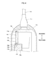
ultrasonic probe 100, which shows that the bubbles are being accumulated within thetube 131. Fig. 4 illustrates a state where theultrasonic probe 100 is placed vertically so that its cover side faces the ground (hereinafter, such a state is referred to as "a bubble-removing state"). - Referring to Fig. 4, in the bubble-removing state, the
bubbles 116a float up rearward (toward the side opposite to the cover 113) due to their buoyancies. The floating upbubbles 116a reach the vicinity of theinlet 132b of the communication portion. Then, thebubbles 116a enter theinlet 132b and gather in thecommunication passage 132a. When only a single bubble enters thecommunication passage 132, saidbubble 116a moves up along a sloped surface of thecommunication passage 132a due to its buoyancy and passes through theoutlet 132c to enter the inside of thetube 131. When a number of bubbles enters thecommunication passage 132a, saidbubbles 116a gather in the vicinity of theoutlet 132c and then pass through theoutlet 132c in order to enter the inside of thetube 131 due to their buoyancies one by one. - When the ultrasonic probe 110 is left in the bubble-removing state, the
bubbles 116a continuously enter the inside of thetube 131 and can be accumulated inside thetube 131 from the vicinity of theother end 134 of thetube 131. Theultrasonic probe 100 may be left in the bubble-removing state when theultrasonic probe 100 is placed for a certain period of time after ending assembly in the state where its cover side faces the ground. Alternatively, theultrasonic probe 100 may be left in the bubble-removing state when ultrasonic diagnosis can be carried out using theultrasonic probe 100. In both cases, removing and accumulating the bubbles take place as described above. Particularly, when thecover 113 is made from an elastic material, if the cover is slightly pressed toward the inside of the ultrasonic probe during the ultrasonic diagnosis, then thebubbles 116a, which gather in thecommunication passage 132a, are allowed to enter the inside of thetube 131 more easily due to the pressure applied to the liquid medium. - Fig. 5 shows a state where the accumulated bubbles are not discharged again (contrary to the state shown in Fig. 4). When the
ultrasonic probe 100 is not utilized, theultrasonic probe 100 may be placed on any fixture (e.g., aprobe holder 20 provided on the main body of the ultrasonic diagnostic apparatus). In such a case, thebubbles 116a accumulated within thetube 131 float up along thetube 131 toward theoutlet 132c. However, since the diameter of theoutlet 132c is very narrow, the floating upbubbles 116a are difficult to move through theoutlet 132c toward theinlet 132b. Furthermore, the floating upbubbles 116a are restricted from being discharged to the inside of the housing through the rearmost portion of the housing by theother end 133c of the connector. Although a very small amount of bubbles, among the accumulated bubbles, can enter the inside of thehousing 112 through theoutlet 132c, such bubbles can be removed from theliquid medium 116 again whenever theultrasonic probe 100 is in the bubble-removing state. Consequently, thebubbles 116a remaining in theliquid medium 116 are allowed to be accumulated in thetube 131 while being removed successively. Even when theultrasonic probe 100 is placed horizontally, the bubbles already accumulated in thetube 131 are difficult to be discharged to thehousing 112 due to the structure of the bubble-removingdevice 130. - Fig. 6 shows an alternative to the bubble-removing device shown in Fig. 3 in the bubble-removing state. In a bubble-removing device 130' shown in Fig. 6, the
tube 131 includes ablocking plate 131a therein. The blockingplate 131a is sloped toward theother end 134 and blocks the inside of thetube 131 with a gap, which is sized such that the bubbles can move therethrough. A plurality of blocking plates may be included inside thehousing 112. The communication portion 132' includes a funnel-shaped or a truncated cone-shapedcommunication passage 132a', which becomes narrow as it proceeds toward theother end 134. The connector 133' has a barrel shape to define acavity 133d together with the communication portion 132'. In the bubble-removing state, thebubbles 116a move through theoutlet 132c and enter the inside of thetube 131. Also, the bubbles move up along the blockingplate 131 a and reach theother end 134 of thetube 131 so as to be accumulated in thetube 131. - Fig. 7 is a sectional view of the bubble-removing device 130' when the ultrasonic probe is placed in an opposite state to the bubble-removing state.
- In the state shown in Fig. 7, the
bubbles 116a accumulated in thetube 131 float up toward theoutlet 132c along thetube 131 once again. In such a case, a substantial portion of the accumulatedbubbles 116a are caught between the inner wall of thetube 131 and theblocking plate 131a and are retained therein. Theuncaught bubbles 116a go through the gap between the inner wall of thetube 131 and theblocking plate 131a and then float up toward theoutlet 132c. However, said bubbles cannot easily pass through theoutlet 132c toward theinlet 132b due to the verynarrow outlet 132c. Further, since thecavity 133d has a broader cross-sectional area than that of theoutlet 132c, most of the uncaught and floating up bubbles enter thecavity 133d. - Fig. 8 is a partially cutaway perspective view of an ultrasonic probe, which is constructed in accordance with a second embodiment of the present invention. The
ultrasonic probe 200 of this embodiment has the same configuration as theultrasonic probe 100 of the first embodiment, except that the bubble-removing device is configured to allow the injection of the liquid medium. - Referring to Fig. 8, the bubble-removing
device 230 comprises a tubular member and a communication portion (not shown) for permitting the bubbles to pass into the tubular member and restricting a counter passing thereof. The tubular member is joined to the rearmost portion (e.g.,extended portion 112b) of the housing at its one end in such a manner that it penetrates the wall of theextended portion 112b. The other end of the tubular member is closed and configured to allow the injection of the liquid medium. The communication portion is disposed at the one end of the tubular member. - The tubular member includes a
tube 231, which is made from a soft material (e.g., rubber) or a hard material (e.g., plastic) and is bent at one portion thereof. Thetube 231 extends rearward vertically from therearmost portion 112b of thehousing 112 and is bent in the vicinity of the rearward inner wall of thecase 114. It further extends along the rearward inner wall of thecase 114. In the vertical extending portion of thetube 231, there may be provided theblocking plate 131a shown in Fig. 6. - One end of the
tube 231 consists of aconnector 233, which is joined to a medium injection port of the rearmost portion of the housing. The closedother end 234 of thetube 231 consists of aninjection port 234a fitted to thetube 231 and aplug 234b for sealing theinjection port 234a. Theinjection port 234a is retained in the inner wall of thecase 114 by being engaged to a hook-shapedinjection port holder 114a provided on a rearmost portion of the inner wall of thecase 114, thereby being located farther away from thecover 112 than theconnector 233. - Fig. 9 is a sectional view of the bubble-removing
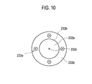
device 230 shown in Fig. 8. Fig. 10 is a bottom view of theconnector 233 of the bubble-removingdevice 230. - The
connector 233 includes the following: a barrel-shapedconnector body 233a; oneend 233b facing the inside of thehousing 112; and theother end 233c to which a body of thetube 231 is coupled. The oneend 233b is formed with an opening. - The
communication portion 232, which is disposed at the one end of the tube 231 (more specifically, the connector 233), includes the following: a funnel-shapedcommunication passage 232a, which becomes narrow as it proceeds toward theother end 234; and aninlet 232b and anoutlet 232c formed at both ends of thecommunication passage 232a. Theinlet 232b is coupled to the opening formed at the oneend 233b of the connector. Theoutlet 232c is opened toward the inside of thetube 231. The size of theoutlet 232c is much smaller than that of theinlet 232b due to the funnel shape of thecommunication passage 232a. The size of theoutlet 232c is determined such that one of the bubbles remaining in the liquid medium can pass through theoutlet 232c. Acavity 233d is formed between the inner wall of theconnector body 233a and thecommunication portion 232 in theconnector 233. - The
communication portion 233 further includes a plurality of funnel-shaped through-holes 233e at its oneend 233b. The through-holes 233e are located adjacent to theinlet 232c. The through-hole 233e becomes narrow as it proceeds toward the inside of theconnector body 233a. - If the liquid medium is filled in the enclosed space to some level during assembly of the
ultrasonic probe 200, then the bubble-removingdevice 230 is joined to themedium injecting port 112e and the injection of the liquid medium is continued. In such a case, the liquid medium is injected into thehousing 112 through theoutlet 232c of the communication portion and the through-holes 233e. At the same time, the air inside thehousing 112 can be discharged through one of theoutlets 232c and the through-holes 233e. If the liquid medium is injected into the vicinity of theinjection port 234a, then theinjection port 234a is plugged with theplug 234b and theinjection port 234a is secured to thecase 114. Thereafter, the assembly of theultrasonic probe 200 is continued. As such, the bubble-removingdevice 200 may be used to inject the liquid medium during the assembly of the ultrasonic prove 200 and remove the bubbles remaining in the filled liquid medium after theultrasonic probe 200 is completely assembled. - Embodiments of the present invention may provide an ultrasonic probe. The ultrasonic probe of the present invention can simply and successively remove the bubbles remaining in the liquid medium filled in the enclosed space, wherein the ultrasonic element is reciprocated. When the ultrasonic probe is vertically placed so that the cover faces the ground or when the ultrasonic diagnosis is carried out with the ultrasonic probe, the bubbles can be removed from the liquid medium.
- An ultrasonic probe may be provided. The ultrasonic probe of the present invention may comprise an ultrasonic element, a housing, a drive device, a cover, a liquid medium and a device for removing bubbles. The housing may support the ultrasonic element so that the ultrasonic probe can be reciprocated therein. The drive device may be secured to the housing to reciprocate the ultrasonic element. The cover may be joined to the housing to define an enclosed space in which the ultrasonic element is reciprocated. The liquid medium may be filled in the enclosed space. The bubble-removing device may include a tubular member and a communication passage. The tubular member may be joined at one end to a portion of the housing opposed to the cover to be in communication with the enclosed space. The tubular member may be located so that a closed other end is farther away from the cover than the one end. The communication passage may be disposed at the one end and becomes narrow as it proceeds toward the other end. The communication passage may have a shape of a funnel or a truncated cone. A blocking plate may be provided inside the tubular member. The blocking plate may partially close the inside of the tubular member and be sloped toward the other end.
- Any reference in this specification to "one embodiment," "an embodiment," "example embodiment," etc., means that a particular feature, structure or characteristic described in connection with the embodiment is included in at least one embodiment of the present invention. The appearances of such phrases in various places in the specification are not necessarily all referring to the same embodiment. Further, when a particular feature, structure or characteristic is described in connection with any embodiment, it is submitted that it is within the purview of one skilled in the art to effect such feature, structure or characteristic in connection with other ones of the embodiments.
- Although embodiments have been described with reference to a number of illustrative embodiments thereof, it should be understood that various other modifications and embodiments can be devised by those skilled in the art that will fall within the spirit and scope of the principles of this disclosure. More particularly, numerous variations and modifications are possible in the component parts and/or arrangements of the subject combination arrangement within the scope of the disclosure, the drawings and the appended claims. In addition to variations and modifications in the component parts and/or arrangements, alternative uses will also be apparent to those skilled in the art.
Claims (3)
- An ultrasonic probe (100, 200), comprising:an ultrasonic element (111a);a housing (112) for reciprocably supporting the ultrasonic element (111a);a drive device (120) secured to the housing (112) for reciprocating the ultrasonic element (111a);a cover (113) joined to the housing (112) to define an enclosed space (115), the ultrasonic element (111a) being reciprocated in the enclosed space (115);a liquid medium (116) filled in the enclosed space (115); anda device for removing bubbles (130, 130', 230) including: a tubular member (131, 231) joined at one end to a portion of the housing (112) opposed to the cover (113) to be in communication with the enclosed space (115) and being situated so that a closed other end (134, 234) is farther away from the cover (113) than the one end; and a communication passage (132a, 132a', 232a) disposed at the one end and being narrow as going toward the other end (134, 234).
- The ultrasonic probe of Claim 1, wherein the communication passage (132a, 132a', 232a) has a shape of a funnel or a truncated cone.
- The ultrasonic probe of Claim 1, wherein a blocking plate (131a) is provided inside the tubular member (131, 231) and the blocking plate partially closes the inside of the tubular member and is sloped toward the other end (134, 234).
Applications Claiming Priority (1)
| Application Number | Priority Date | Filing Date | Title |
|---|---|---|---|
| KR1020060065288A KR20080006293A (en) | 2006-07-12 | 2006-07-12 | Ultrasonic Probe with Bubble Removal Device |
Publications (1)
| Publication Number | Publication Date |
|---|---|
| EP1878388A1 true EP1878388A1 (en) | 2008-01-16 |
Family
ID=38521654
Family Applications (1)
| Application Number | Title | Priority Date | Filing Date |
|---|---|---|---|
| EP07013476A Withdrawn EP1878388A1 (en) | 2006-07-12 | 2007-07-10 | Ultrasonic probe with a device for removing bubbles |
Country Status (4)
| Country | Link |
|---|---|
| US (1) | US20080015444A1 (en) |
| EP (1) | EP1878388A1 (en) |
| JP (1) | JP2008018247A (en) |
| KR (1) | KR20080006293A (en) |
Cited By (5)
| Publication number | Priority date | Publication date | Assignee | Title |
|---|---|---|---|---|
| EP2228012A1 (en) * | 2009-03-12 | 2010-09-15 | Medison Co., Ltd. | Probe for ultrasonic diagnosis apparatus |
| CN103169495A (en) * | 2012-12-06 | 2013-06-26 | 广州丰谱信息技术有限公司 | Monitoring method and monitoring device of movable ultrasonic image with high resolution |
| US10149662B2 (en) | 2010-12-27 | 2018-12-11 | Shenzhen Mindray Bio-Medical Electronics Co., Ltd. | 3D mechanical probe |
| EP4014882A1 (en) * | 2020-12-18 | 2022-06-22 | Koninklijke Philips N.V. | Ultrasonic diagnostic apparatus and probe for the same |
| WO2022128724A1 (en) | 2020-12-18 | 2022-06-23 | Koninklijke Philips N.V. | Ultrasonic imaging apparatus and probe for the same |
Families Citing this family (12)
| Publication number | Priority date | Publication date | Assignee | Title |
|---|---|---|---|---|
| US8506490B2 (en) * | 2008-05-30 | 2013-08-13 | W.L. Gore & Associates, Inc. | Real time ultrasound probe |
| CN102112058B (en) * | 2008-08-01 | 2014-03-19 | 皇家飞利浦电子股份有限公司 | Three dimensional imaging ultrasound probe |
| KR101271847B1 (en) * | 2010-12-16 | 2013-06-07 | 삼성메디슨 주식회사 | Ultrasonic probe |
| EP2742870A4 (en) * | 2011-08-08 | 2015-03-04 | Konica Minolta Inc | Ultrasound probe |
| KR102170278B1 (en) * | 2013-07-04 | 2020-10-26 | 삼성메디슨 주식회사 | Ultrasonic probe and ultrasonic image apparatus having the same |
| KR101712552B1 (en) * | 2015-03-11 | 2017-03-07 | 알피니언메디칼시스템 주식회사 | High Intensity Focused Ultrasound Treatment Head |
| CN109979613A (en) * | 2017-12-27 | 2019-07-05 | 核动力运行研究所 | A kind of nuclear reactor pressure container inner wall of the pipe air bubble eliminating device and method |
| KR102154691B1 (en) * | 2017-12-28 | 2020-09-10 | 주식회사 코어테크 | Effective equipment to remove the bubbles of rectal wall in situ High Intensity Focused Ultrasound Therapy for Prostate Disease Treatment |
| WO2021130740A1 (en) | 2019-12-25 | 2021-07-01 | Coral Detection Systems Ltd. | Method of removing underwater bubbles and a device therefor |
| WO2021215511A1 (en) * | 2020-04-24 | 2021-10-28 | 株式会社Luxonus | Matching material bag and matching material bag set |
| CN117119965A (en) | 2021-03-23 | 2023-11-24 | 深圳市理邦精密仪器股份有限公司 | Testing probes, transmission devices and testing instruments |
| CN117090670A (en) * | 2023-06-26 | 2023-11-21 | 深圳科维新技术有限公司 | An ultrasonic probe flow channel structure based on negative pressure cavity to drive away bubbles |
Citations (4)
| Publication number | Priority date | Publication date | Assignee | Title |
|---|---|---|---|---|
| US4316271A (en) * | 1981-01-14 | 1982-02-16 | Honeywell Inc. | Purging and expansion mechanism |
| US4567895A (en) * | 1984-04-02 | 1986-02-04 | Advanced Technology Laboratories, Inc. | Fully wetted mechanical ultrasound scanhead |
| US4807634A (en) * | 1986-02-04 | 1989-02-28 | Kabushiki Kaisha Toshiba | Mechanical type ultrasonic scanner |
| US5531119A (en) * | 1994-04-19 | 1996-07-02 | Capistrano Labs, Inc. | Ultrasound probe with bubble trap |
-
2006
- 2006-07-12 KR KR1020060065288A patent/KR20080006293A/en not_active Ceased
-
2007
- 2007-07-10 EP EP07013476A patent/EP1878388A1/en not_active Withdrawn
- 2007-07-11 US US11/776,274 patent/US20080015444A1/en not_active Abandoned
- 2007-07-12 JP JP2007182787A patent/JP2008018247A/en active Pending
Patent Citations (4)
| Publication number | Priority date | Publication date | Assignee | Title |
|---|---|---|---|---|
| US4316271A (en) * | 1981-01-14 | 1982-02-16 | Honeywell Inc. | Purging and expansion mechanism |
| US4567895A (en) * | 1984-04-02 | 1986-02-04 | Advanced Technology Laboratories, Inc. | Fully wetted mechanical ultrasound scanhead |
| US4807634A (en) * | 1986-02-04 | 1989-02-28 | Kabushiki Kaisha Toshiba | Mechanical type ultrasonic scanner |
| US5531119A (en) * | 1994-04-19 | 1996-07-02 | Capistrano Labs, Inc. | Ultrasound probe with bubble trap |
Cited By (5)
| Publication number | Priority date | Publication date | Assignee | Title |
|---|---|---|---|---|
| EP2228012A1 (en) * | 2009-03-12 | 2010-09-15 | Medison Co., Ltd. | Probe for ultrasonic diagnosis apparatus |
| US10149662B2 (en) | 2010-12-27 | 2018-12-11 | Shenzhen Mindray Bio-Medical Electronics Co., Ltd. | 3D mechanical probe |
| CN103169495A (en) * | 2012-12-06 | 2013-06-26 | 广州丰谱信息技术有限公司 | Monitoring method and monitoring device of movable ultrasonic image with high resolution |
| EP4014882A1 (en) * | 2020-12-18 | 2022-06-22 | Koninklijke Philips N.V. | Ultrasonic diagnostic apparatus and probe for the same |
| WO2022128724A1 (en) | 2020-12-18 | 2022-06-23 | Koninklijke Philips N.V. | Ultrasonic imaging apparatus and probe for the same |
Also Published As
| Publication number | Publication date |
|---|---|
| US20080015444A1 (en) | 2008-01-17 |
| JP2008018247A (en) | 2008-01-31 |
| KR20080006293A (en) | 2008-01-16 |
Similar Documents
| Publication | Publication Date | Title |
|---|---|---|
| US20080015444A1 (en) | Ultrasonic probe with a device for removing bubbles | |
| US4807634A (en) | Mechanical type ultrasonic scanner | |
| KR101113216B1 (en) | Probe of ultrasonic diagnosis apparatus | |
| JP6059432B2 (en) | 3D imaging ultrasound probe | |
| US8506490B2 (en) | Real time ultrasound probe | |
| US20080156577A1 (en) | Ultrasonic transducer system | |
| CA2896114A1 (en) | Focused rotational ivus transducer using single crystal composite material | |
| JP4584321B2 (en) | Ultrasonic probe | |
| EP1938755A2 (en) | Device for rotating a transducer of an ultrasonic probe | |
| US7484412B2 (en) | Ultrasound probe with multiple fluid chambers | |
| JP4422733B2 (en) | Ultrasonic diagnostic equipment | |
| CA1276716C (en) | Ultrasonic mechanical sector scanning transducer probe assembly | |
| US7481115B2 (en) | Ultrasonic probe | |
| WO2022102276A1 (en) | Acoustic lens, method for manufacturing same, ultrasound probe, and ultrasonographic device | |
| JP2005334107A (en) | Ultrasonic probe | |
| US20080200816A1 (en) | Ultrasound diagnostic apparatus, endoscope and ultrasound transducer | |
| JP4473616B2 (en) | Ultrasonic probe | |
| JP3599893B2 (en) | Ultrasound diagnostic equipment | |
| JPH0445690Y2 (en) | ||
| TW202032120A (en) | Ultrasound scanning assembly and ultrasound conductive module | |
| KR20080016021A (en) | Ultrasonic probe | |
| US20240295644A1 (en) | Ultrasonic imaging apparatus and probe for the same | |
| JPS63281044A (en) | Ultrasonic mechanical scanner device | |
| JP2005168614A (en) | Ultrasonic probe | |
| CN115607316A (en) | Electric toothbrush |
Legal Events
| Date | Code | Title | Description |
|---|---|---|---|
| PUAI | Public reference made under article 153(3) epc to a published international application that has entered the european phase |
Free format text: ORIGINAL CODE: 0009012 |
|
| AK | Designated contracting states |
Kind code of ref document: A1 Designated state(s): AT BE BG CH CY CZ DE DK EE ES FI FR GB GR HU IE IS IT LI LT LU LV MC MT NL PL PT RO SE SI SK TR |
|
| AX | Request for extension of the european patent |
Extension state: AL BA HR MK YU |
|
| 17P | Request for examination filed |
Effective date: 20080314 |
|
| 17Q | First examination report despatched |
Effective date: 20080424 |
|
| AKX | Designation fees paid |
Designated state(s): DE FR IT |
|
| STAA | Information on the status of an ep patent application or granted ep patent |
Free format text: STATUS: THE APPLICATION IS DEEMED TO BE WITHDRAWN |
|
| 18D | Application deemed to be withdrawn |
Effective date: 20081105 |