EP1876840A1 - Image display device and image display method - Google Patents
Image display device and image display method Download PDFInfo
- Publication number
- EP1876840A1 EP1876840A1 EP07013099A EP07013099A EP1876840A1 EP 1876840 A1 EP1876840 A1 EP 1876840A1 EP 07013099 A EP07013099 A EP 07013099A EP 07013099 A EP07013099 A EP 07013099A EP 1876840 A1 EP1876840 A1 EP 1876840A1
- Authority
- EP
- European Patent Office
- Prior art keywords
- light source
- image
- observer
- light
- display
- Prior art date
- Legal status (The legal status is an assumption and is not a legal conclusion. Google has not performed a legal analysis and makes no representation as to the accuracy of the status listed.)
- Granted
Links
Images







Classifications
-
- H—ELECTRICITY
- H04—ELECTRIC COMMUNICATION TECHNIQUE
- H04N—PICTORIAL COMMUNICATION, e.g. TELEVISION
- H04N13/00—Stereoscopic video systems; Multi-view video systems; Details thereof
- H04N13/30—Image reproducers
- H04N13/302—Image reproducers for viewing without the aid of special glasses, i.e. using autostereoscopic displays
- H04N13/305—Image reproducers for viewing without the aid of special glasses, i.e. using autostereoscopic displays using lenticular lenses, e.g. arrangements of cylindrical lenses
-
- G—PHYSICS
- G02—OPTICS
- G02B—OPTICAL ELEMENTS, SYSTEMS OR APPARATUS
- G02B30/00—Optical systems or apparatus for producing three-dimensional [3D] effects, e.g. stereoscopic images
- G02B30/20—Optical systems or apparatus for producing three-dimensional [3D] effects, e.g. stereoscopic images by providing first and second parallax images to an observer's left and right eyes
- G02B30/26—Optical systems or apparatus for producing three-dimensional [3D] effects, e.g. stereoscopic images by providing first and second parallax images to an observer's left and right eyes of the autostereoscopic type
- G02B30/27—Optical systems or apparatus for producing three-dimensional [3D] effects, e.g. stereoscopic images by providing first and second parallax images to an observer's left and right eyes of the autostereoscopic type involving lenticular arrays
-
- G—PHYSICS
- G02—OPTICS
- G02B—OPTICAL ELEMENTS, SYSTEMS OR APPARATUS
- G02B30/00—Optical systems or apparatus for producing three-dimensional [3D] effects, e.g. stereoscopic images
- G02B30/20—Optical systems or apparatus for producing three-dimensional [3D] effects, e.g. stereoscopic images by providing first and second parallax images to an observer's left and right eyes
- G02B30/26—Optical systems or apparatus for producing three-dimensional [3D] effects, e.g. stereoscopic images by providing first and second parallax images to an observer's left and right eyes of the autostereoscopic type
- G02B30/30—Optical systems or apparatus for producing three-dimensional [3D] effects, e.g. stereoscopic images by providing first and second parallax images to an observer's left and right eyes of the autostereoscopic type involving parallax barriers
-
- H—ELECTRICITY
- H04—ELECTRIC COMMUNICATION TECHNIQUE
- H04N—PICTORIAL COMMUNICATION, e.g. TELEVISION
- H04N13/00—Stereoscopic video systems; Multi-view video systems; Details thereof
- H04N13/30—Image reproducers
- H04N13/302—Image reproducers for viewing without the aid of special glasses, i.e. using autostereoscopic displays
- H04N13/31—Image reproducers for viewing without the aid of special glasses, i.e. using autostereoscopic displays using parallax barriers
-
- H—ELECTRICITY
- H04—ELECTRIC COMMUNICATION TECHNIQUE
- H04N—PICTORIAL COMMUNICATION, e.g. TELEVISION
- H04N13/00—Stereoscopic video systems; Multi-view video systems; Details thereof
- H04N13/30—Image reproducers
- H04N13/366—Image reproducers using viewer tracking
-
- G—PHYSICS
- G02—OPTICS
- G02B—OPTICAL ELEMENTS, SYSTEMS OR APPARATUS
- G02B27/00—Optical systems or apparatus not provided for by any of the groups G02B1/00 - G02B26/00, G02B30/00
- G02B27/0093—Optical systems or apparatus not provided for by any of the groups G02B1/00 - G02B26/00, G02B30/00 with means for monitoring data relating to the user, e.g. head-tracking, eye-tracking
Definitions
- the present invention relates to an image display device and an image display method for displaying an image with the image being changed according to an observer's viewing direction.
- a display technique of images for controlling a light source which is visible from an observer by disposing a shielding such as a parallax barrier, or an optical element such as a lenticular sheet or a lens array in front of a light source array such as a liquid crystal display.
- the display technique produces parallax since the observed image varies according to the position of the observer. Since the technique realizes binocular parallax when both eyes are used for observation, it is applied to a three dimensional (3D) display, as well as an image display device which can provide different images to be observed for respective observers, for example, when the same display is observed from a driver's seat and a passenger's seat in a car.
- Fig. 1 illustrates an exemplary display using a parallax barrier
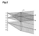
- Fig. 2 illustrates an exemplary display using a lenticular sheet.
- the display includes a light source array (light sources 1 to 8), the light source array corresponding to each pixel of the liquid crystal display, for example.
- Figs. 1 and 2 show that light emitted from the light sources 1, 3 and 5 is visible from respective directions of the corresponding arrows. Although other light sources are not illustrated, they are similarly visible from the respective corresponding angular directions. In any of the techniques, an area in which each light source array is visible is limited, thereby allowing a three-dimensional image to be displayed by producing binocular parallax.
- the display shown in Figs. 1 and 2 is an example of a four-view display, however a stereo display (two-view) and a multi-view display for displaying multi-view images are similar in principle.
- IP integral photography
- the above-mentioned light beam control element controls the observer's viewing area for several light source arrays to realize multi-view (including two-view, i.e., stereo vision) display.
- a slit or a cylindrical lens constituting the lenticular sheet is provided for four light sources (i.e., four pixels), and the slits or the cylindrical lenses control the area in which the observer can view the light emitted from the light source.
- a parallax barrier, a lenticular sheet, or a lens array there exists an area for each of the 3D pixels in which a 3D image can be normally observed.
- Fig. 3 is an explanatory view illustrating the area in which a 3D image can be observed when a lenticular sheet is used.
- the output direction of the light is changed by the action of the cylindrical lens constituting the lenticular sheet 11 for the 3D pixels (light sources 5 to 8), so that an area in which the light is visible, i.e., viewing area is produced.
- the parallax barrier method is similar in principle, except that the disposed lenticular sheet is an element for periodically providing a shield and an opening in repetition (see Fig. 1).
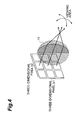
- Fig. 4 is an explanatory view illustrating a case using a nine-view IP method composed of a vertically three-parallax 3D pixel b1 and a horizontally three-parallax 3D pixel b2.
- the lenticular sheet 11 which is the light beam control element similarly controls the parallaxes along nine directions vertically and horizontally.
- patent literature 1 Japanese Patent Application No. 7-270745
- patent literature 2 Japanese Patent Application Laid-Open No. 2002-296540 .
- the techniques described in patent literatures 1 and 2 relate to a 3D image display device, wherein 3D images can be displayed by displaying pixels for the left eye and pixels for the right eye, and images according to the position of the observer can be displayed by turning the barrier on and off.
- Patent Literature 1 Japanese Patent Application Laid-Open No. 7-270745
- Patent Literature 2 Japanese Patent Application Laid-Open No. 2002-296540
- Fig. 5 shows a situation in which a repetitive image is visible in the case of the lenticular method.
- the light sources 1 to 4 in Fig. 5 compose the 3D pixel a, while the light sources 5 to 8 compose 3D pixel b.
- Fig. 5 shows a situation in which a repetitive image is visible in the case of the lenticular method.
- the light sources 1 to 4 in Fig. 5 compose the 3D pixel a, while the light sources 5 to 8 compose 3D pixel b.
- an object of the present invention to provide an image display device and an image display method which can display unnaturalness-free images without showing the observer repetitive images according to the observer's viewpoint.
- an image display device of the present invention comprises a light source means having light sources for emitting light corresponding to a plurality of pixels composing an image to be displayed; a light beam control means for limiting a viewing area of the image formed by the light emitted from the light source means; a detection means for detecting a relative positional relationship between an observer's eye observing the image formed by the light emitted from the light source means, and the light source means and the light beam control means; and an image control means for controlling, in accordance with the positional relationship detected by the detection means, the light source means to change display contents of the light forming the image with the viewing area limited by the light beam control means.
- an image display method of the present invention is an image display method of the image display device that comprises: a light source means having light sources for emitting light corresponding to a plurality of pixels composing an image to be displayed, and a light beam control means for limiting a viewing area of the image formed by the light emitted from the light source means, the method comprising: a detection step of detecting a relative positional relationship between an observer's eye observing the image formed by the light emitted from the light source means, and the light source means and the light beam control means; and an image control step of controlling, in accordance with the positional relationship detected by the detection step, the light source means to change display contents of the light forming the image with the viewing area limited by the light beam control means.
- the viewing area of the image formed by the light emitted from the light source detect a relative positional relationship between the observer's eye observing the image formed by the light emitted from the light source means and the light source; and, in accordance with the detected positional relationship, change display contents of the light composing the image with limited viewing area.
- This allows displaying unnaturalness-free images without showing the observer repetitive images according to the observer's viewpoint.
- the light source means of the image display device of the present invention display images using a light source array. With this arrangement, images can be displayed using the light source array.
- the light beam control means of the image display device of the present invention be a lenticular sheet having cylindrical lenses consecutively arranged thereon.
- the light beam control means of the image display device of the present invention be a parallax barrier having vertical slits periodically arranged thereon.
- the light beam control means of the image display device of the present invention be a liquid crystal lens or a holographic optical element which can electrically control refractive index and amplitude transmittance.
- the light beam control means of the image display device of the present invention be a lens array of two-dimensionally arranged lenses.
- the detection means of the image display device of the present invention detect at least one of the position of the display means including the light source means, the inclination of the display means with respect to the observer's gaze direction (line-of-sight direction), and the position of the eyes and the gaze direction of the observer observing the image displayed by the display means.
- the image control means of the image display device of the present invention control the light source means, when the observer is located at a position other than a predefined normal viewing area in which an image formed by the light emitted from one light source of the light source means is visible, so that the light source means does not output, from the light emitted from the one light source of the light source means, an image corresponding to the position within the normal viewing area, if the detection means determines that the observer is located at a position within a repetitive area in which an image formed by the light emitted from the one light source of the light source means is visible.
- the image control means of the image display device of the present invention control the light source means, if the detection means detects that the observer is located within a shielded area in which light emitted from the one light source is not visible, so that the light source means does not output an image being emitted from the light source means to the normal viewing area.
- the image control means of the image display device of the present invention control the light source means, if the detection means detects that the observer is located at a position within the repetitive area for the one light source, so that the light source means emits light from the one light source to complement the image formed by the light emitted from other light sources having the position as the normal viewing area.
- the present invention can display unnaturalness-free images without showing the observer repetitive images according to the observer's viewpoint.
- Fig. 1 is a block diagram illustrating an arrangement of a display using a parallax barrier.
- Fig. 2 is a block diagram illustrating an arrangement of a display using a lenticular sheet.
- Fig. 3 is an explanatory drawing of a viewing area in the display using the lenticular sheet.
- Fig. 4 is an explanatory drawing of the viewing area in a display using an IP method.
- Fig. 5 is an explanatory drawing of a principle of how a repetitive image is generated on the display using the lenticular sheet.
- Fig. 6 is a block diagram illustrating an arrangement of an image display device of the first embodiment.
- Fig. 7 is an explanatory drawing of a line of sight on the display using a parallax barrier.
- Fig. 8 is an explanatory drawing of a viewing area on the display using the parallax barrier.
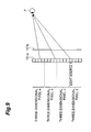
- Fig. 9 is an explanatory drawing of generation of a repetitive image on the display using the parallax barrier.
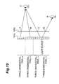
- Fig. 10 is an explanatory drawing of displaying a normal image on the display using the parallax barrier.
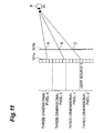
- Fig. 11 is an explanatory drawing of displaying a normal image in place of the repetitive image on the display using the parallax barrier.
- Fig. 12 is an explanatory drawing illustrating that the shielded area is bisected when executing image control on the display using the parallax barrier.
- Fig. 13 is an explanatory drawing of the display using a cylindrical lens.
- Fig. 14 is a block diagram illustrating the arrangement of an image display device of the second embodiment.
- Fig. 15 is a block diagram illustrating the arrangement of an image display device of the third embodiment.
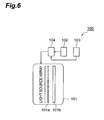
- the image display device comprises, as shown in Fig. 6, a display 101 (including a light source array 101a (light source means), a light beam control element 101 b (light beam control means)), a terminal position detection sensor 102 (detection means), an observer position detection sensor 103 (detection means), and a display image control device 104 (image control means).
- a display 101 including a light source array 101a (light source means), a light beam control element 101 b (light beam control means)), a terminal position detection sensor 102 (detection means), an observer position detection sensor 103 (detection means), and a display image control device 104 (image control means).
- the display 101 includes a light source array 101a, and a light beam control element 101b.
- the light source array 101a is a light source of light which forms multi-view images and outputs a plurality of images in pixel units.
- the light source array 101a may be respective pixels of the liquid crystal display, or may be luminous bodies such as LEDs being disposed.
- the light beam control element 101b is provided on the display surface side of the light source array 101a so that it can limit the position at which each of the light sources composing the light source array 101a is visible.
- the light beam control element 101b may be a parallax barrier which shields the light output from the light source array 101a, a lenticular sheet which is an optical element such as a cylindrical lens for controlling the direction of light beam, or an optical element such as a liquid crystal lens or a holographic optical element (HOE) for electrically controlling refractive index and amplitude transmittance.
- a parallax barrier which shields the light output from the light source array 101a
- a lenticular sheet which is an optical element such as a cylindrical lens for controlling the direction of light beam
- an optical element such as a liquid crystal lens or a holographic optical element (HOE) for electrically controlling refractive index and amplitude transmittance.
- HOE holographic optical element
- the terminal position detection sensor 102 is a sensor for detecting at least one of, the position, direction, and inclination of the display 101.
- the terminal position detection sensor 102 may be an inclination sensor or an acceleration sensor attached to the display 101, or may be an infrared sensor, an ultrasonic sensor or a camera (imaging device).
- these sensors may be provided in external environment to detect the position, direction, or inclination of the display 101.
- the terminal position detection sensor 102 composed of these sensors can detect the position, direction, or inclination in the space in which the display 101 exists.
- the position of the display detected by the terminal position detection sensor 102 is virtually specified by three axes x, y, and z in the space, the terminal position detection sensor 102 being capable of detecting the point along the coordinate axes on which the display 101 exists and detecting the direction toward which the display 101 is facing.
- the terminal position detection sensor 102 can determine the position and inclination of the display 101 in the space by detecting, among the parts composing the display 101, three or more different parts and their positions. Similarly, the terminal position detection sensor 102 can determine the position and inclination of the display 101 in the space by detecting one of the parts composing the display 101 and the angle of inclination of the display 101 itself to the three axes.
- the sensors for estimating the position of the display 101 those such as the above-mentioned inclination sensor, the acceleration sensor, the infrared sensor, the ultrasonic sensor or the camera can be used.
- the inclination sensor or the acceleration sensor can detect the inclination angle to the three axes, the angular velocity, the angular acceleration, the transfer speed, and the acceleration, and convert the detected information into the position or the inclination angle to the three axes of the display 101.
- the infrared or ultrasonic sensor can generate infrared light or ultrasonic wave toward the display 101, receive the reflection, and estimate the position of the display 101.
- an infrared light / ultrasonic wave generator provided on the display 101 can generate infrared light or ultrasonic wave toward external environment and estimate the position of the display 101 by receiving the reflection.
- the position and inclination of the display 101 can be estimated from camera images. In this case, the position or inclination of the display 101 may be estimated by disposing markers or the like in the external environment or on the display 101 itself as feature points, or by extracting feature points by image processing.
- the sensor or camera as the terminal position detection sensor 102 may be used in combination of two or more types of devices, or may be used in combination of a plurality of identical sensors.
- reliability of operation can be enhanced by using information from individual sensors.
- devices such as a camera may be greatly affected by brightness in the external environment, and however the inclination sensor or the like will not be affected by brightness.
- inclination sensors have a lower precision due to accumulated errors because they usually evaluate variation of inclination amount relative to the initial state, and due to the fact that they do not directly detect the observer's position. Therefore, it is preferred that both the camera and inclination sensor be used in combination, whereby suppressing the above-mentioned shortcoming during operation.
- the observer position detection sensor 103 is a sensor for detecting the observer's position.
- the observer's position may be a relative position with respect to the display 101, or a coordinate value relative to three virtual axes x, y and z defined in the space.
- the observer position detection sensor 103 may be an acceleration sensor, an infrared sensor, an ultrasonic sensor or a camera carried by the observer, or may be an infrared sensor, an ultrasonic sensor or camera provided on the display 101, or may be an infrared sensor, an ultrasonic sensor or a camera provided in the external environment.
- a representative site such as the position of the observer's face may be used instead.
- an acceleration sensor an infrared sensor, an ultrasonic sensor or a camera carried by the observer as the observer position detection sensor 103, and when providing these sensors in the external environment, a similar process as with the terminal position detection sensor 102 can be executed to estimate the observer's position.
- a similar process as with the terminal position detection sensor 102 can be executed to estimate the observer's position.
- obtainable information will be that indicating the relative position to the display 101.
- an imaging device such as a camera to photograph the observer himself and estimate the observer's position
- the sensors and camera mentioned above may be used in combination of two or more types, or a plurality of devices of an identical type. When used in combination, reliability of operation can be enhanced by using information from individual sensors.
- the display image control device 104 can calculate the relative positional relationship between the display 101 and the observer based on the position of the display 101 and the observer's position detected by the terminal position detection sensor 102 and the observer position detection sensor 103, and control to change images to be displayed by the light source array 101a based on the positional relationship. Details of the control to change images to be displayed will be described below.
- the image display device capable of displaying multi-view images is constituted by combining the light source array 101a and the light beam control element 101b provided on its display surface side to constitute the display 101.
- the light source array 101a is typically provided in a two-dimensional space so that multi-view images can be displayed for the observer, with the light beam control element 101b limiting the range in which the observer can observe the light emitted from these light sources.
- a conceptual diagram illustrating the principle of displaying multi-view images is shown in Fig. 7.
- the light beam control element 101b is a barrier (a parallax barrier) formed by periodically placing shieldings and openings, a lenticular sheet formed by periodically disposing cylindrical lenses.
- Fig. 7 is an explanatory drawing illustrating the relationship between the light source and the viewing area when a parallax barrier is employed as the light beam control element 101b, wherein the arrangement is similar to a conventional four-view display, providing similar functionality.
- a 3D pixel a is composed of light sources 1 to 4.
- the 3D pixel a composed of the light sources 1 to 4 is under control of the display image control device 104 to display, toward the direction indicated by the arrows shown in Fig. 7, respectively, view-dependent images which are suited for respective directions. In other words, it is controlled by the light beam control means so that the displayed images look different according to the line of sight (gaze direction)).
- the present embodiment can be embodied in similar manner when seen not as a 3D display but as a display for displaying four different images according to the observer's position.
- the observer can observe the light (image) output from the light source array 101a through a slit A. Then, a multi-view image can be displayed for the observer because visible light sources 1 to 4 are different according to the position of the observer (or his/her eye balls, to be more precise), and it becomes possible to display a 3D image by controlling so that different light sources are visible to both eyes. Actually, the observer can not view these images correctly in all of the areas, since there is a limitation in the range in which the observer can view respective light sources 1 to 4, description of which will be given below referring to Fig. 8.
- the light beam control element 101b has slits A to C formed thereon, corresponding to 3D pixels a to c each of which composed of light sources 1 to 4, wherein respective light sources 1 to 4 are originally supposed to be observed through their corresponding slits A to C.
- the light source 1 is one of the four light sources composing the 3D pixel a and is supposed to be observed through the slit A.
- the observer when the observer is inside a area indicated by the viewing area A_1 of Fig. 8, the image from the light source 1 is observed by the observer through slit A just as supposed to be. This area will be referred to as a "normal viewing area" in the present embodiment.
- the observer moves to a line connecting the light source 1 and the slit B (viewing area B_1) or a line connecting the light source 1 and the slit C (viewing area C_1), the image emitted from the light source 1 is observed by the observer as a repetitive images.
- this area will be referred to as "repetitive area”.
- an area which is neither a normal viewing area nor a repetitive area will be referred to as a "shielded area" in the present embodiment, because the observer cannot observe the image from the light source 1 through any of the slits.
- the terminal position detection sensor 102 and the observer position detection sensor 103 detect the observer's position relative to respective light sources 1 to 4.
- the terminal position sensor 102 and the observer position detection sensor 103 can calculate the combination of the positions of the terminal and the observer, or the relative positional relationship between the terminal and the observer.
- the display image control device 104 can estimate which one of the areas relative to respective light sources 1 to 4 the observer is currently located within: the normal viewing area, the repetitive area, or the shielded area, and can control the information (image) to be displayed by the light source array 101a.
- FIG. 9 A specific state will be described referring to Figs. 9 and 10.
- the display image control device 104 displays a view-dependent image as if it is a fifth light source (pixel) composing the 3D pixel c, for light source which should have formed a 3D pixel d.
- pixel light source
- the display image control device 104 controls the light source array 101a so as to execute a process without providing unnaturalness in the repetitive area, for all the light sources with the observer's position P being the repetitive area.
- the display image control device 104 may execute a process of displaying nothing, that is, not turning on the light source, instead of displaying a new view-dependent image for the light source composing the adjacent 3D pixel. In this case, although there is no effect of expanding the viewing area, repetitive images will not be perceived which has been problematic in the past.
- the display image control device 104 estimates the positional relationship between respective light sources composing the light source array 101a and the observer based on the positional information provided by the terminal position sensor 102 and the observer position detection sensor 103, and controls the information to be displayed for respective light sources in the light source array 101a.
- the display image control device 104 switches the information to be provided to the light sources, according to the estimated positional relationship between the light sources and the observer.
- the observer P is located at a position (n) which is a normal viewing area for light source 1 and can observe the image formed by the light emitted from the light source 1. Subsequently, the observer P (his/her eye balls) moves to a position (m) shown in Fig. 10. Thus, the observer P is located in the normal viewing area for a light source emitting light which is the line of sight indicated by the arrow shown in Fig. 10, whereas the observer P is located in the shielded area for the light source 1. Up to here, the observer P does not perceive a repetitive image. If the observer P moves to a position (1) shown in Fig.
- the light source which can be observed through slit C is not one of the four light sources composing the original 3D pixel c, but the light source 1 composing the 3D pixel d adjacent to the 3D pixel c, whereby displaying a repetitive image.
- the position (m) of the observer P shown in Fig. 10 is a shielded area for the light source 1 of the 3D pixel d, in which any change of the information to be provided to the light source 1 will not be perceived by the observer.
- the image to be displayed can be changed without letting the observer recognize that the display has been switched by preliminarily changing the information to be displayed by the light source 1, considering the possibility that observer may move.
- the light source 1 is controlled so that an image for complementing the image can be output through slit C, based on the image from slits A and B, i.e., the light sources from which the light is emitted.
- the light source 1 is controlled so that an image for complementing the image can be output through slit C, based on the image from slits A and B, i.e., the light sources from which the light is emitted.
- the timing of changing the light to be emitted from the light source 1 is determined by the display image control device 104 executing the process shown in Fig. 12 on the light source within the shielded area.
- the light source 1 shown in Fig. 12 is a light source designed under an assumption that observation is performed through slit A, with its normal viewing area being an area ( ⁇ ) in the drawing.
- a shielded area ( ⁇ ) above the area ( ⁇ ) there is a shielded area ( ⁇ ) above the area ( ⁇ ), and further thereabove is a repetitive area ( ⁇ ) located at a position from where the light source 1 can be observed through slit B.
- the observing area of the light source usually has only one normal viewing area, with shielded areas on both sides thereof and repetitive areas on further both sides of the shielded areas, and from them on the shielded and repetitive areas appear alternately.
- the shielded area ( ⁇ ) bisecting the shielded area ( ⁇ ) defines an area ( ⁇ ') and an area ( ⁇ "), based on which one of the areas they are closer to: the normal viewing area or the shielded area, existing on both sides (above and beneath, in the drawing) of the shielded area ( ⁇ ).
- the observer When the observer is located inside the shielded area ( ⁇ ), the light source 1 cannot be observed through any of slits A or B. Therefore, the observer cannot perceive, if any, information being displayed, that is, if the light source array is a liquid crystal display, for example, regardless of whether the pixel corresponding to the light source 1 is turned on or off.
- the light source 1 composing the 3D pixel a is controlled so as to display the information as the 3D pixel a, since it is assumed that, when the observer is inside the area ( ⁇ '), i.e., the shielded area close to the normal viewing area, the observer observes through slit A.
- the light source 1 can be controlled so as to preliminarily display the information composing the 3D pixel b, whereby displaying a natural 3D image having a wide viewing area without letting the observer recognize unnaturalness of the image when the observer's position moves from the shielded area to the normal viewing area or the repetitive area.
- the display image control device 104 determines, based on the positional information detected by the terminal position detection sensor 102 and the observer position detection sensor 103, respectively, which one of the areas ( ⁇ ') or ( ⁇ ") the observer P is currently located, and may execute a control to change the image to be output at the light source 1.
- whether the observer is in area ( ⁇ ') or area ( ⁇ ") can be determined in the following manner: since the boundary between the area ( ⁇ ') and area ( ⁇ ") is defined according to the relative positional relationship among the light source 1, slit A, and slit B, the display image control device 104 can determine that the observer is in the area ( ⁇ ') if the observer is located closer to the repetitive area ( ⁇ ) than the boundary. If, on the other hand, the observer is located closer to the normal viewing area ( ⁇ ) than the boundary, the display image control device 104 can determine that the observer is in the area ( ⁇ ").
- the present embodiment provides the description basically assuming that the light beam control element 101b is a parallax barrier.
- the light beam control element 101b is a lens or a HOE
- the normal viewing area, shielded area, and repetitive area can be similarly defined for respective light sources to realize the image display device in the present embodiment by executing a process similar to what has been described above.
- the light beam control element 101b is a cylindrical lens.
- Fig. 13 is an explanatory drawing illustrating the normal viewing area, shielded area, and repetitive area when the light beam control element 101b uses a cylindrical lens.
- the normal viewing area, repetitive area, and shielded area can be defined similarly for respective light sources, and the image display device of the present embodiment can be realized by a similar process with the only difference being that slit A and slit B are replaced by a cylindrical lens. Additionally, as stated above, on the other hand, the image display device of the present embodiment can be realized as long as an area in which the light source is visible and an area in which it is not visible can be generated with regard to the positional relationship between the light source and the observer.
- the normal viewing area, shielded area, and repetitive area are generated in the horizontal direction when the 3D display is a lenticular display
- the normal viewing area and repetitive area may be similarly generated also in the vertical direction if usual lens array is used instead of a lenticular lens.
- the viewing area can be expanded for both the horizontal and vertical directions.
- An image display device 100 is designed such that the viewing area of the image formed by the light emitted from the light source array 101a is limited by the light beam control element 101b; the relative positional relationship between the observer's eyes observing the image composed of the light and the light source is detected by the terminal position detection sensor 102 and the observer position detection sensor 103; and display contents of the light composing the image with the limited viewing area can be changed by the display image control device 104 according to the detected positional relationship. In this manner, unnaturalness-free images can be displayed without showing the observer a repetitive image according to the observer's viewpoint.
- the light control element 101b may be a lenticular sheet having cylindrical lenses consecutively arranged thereon, or a parallax barrier having vertical slits periodically arranged thereon.
- a holographic optical element which can electrically control refractive index and amplitude transmittance may be used.
- a lens array of two-dimensionally arranged lenses may also be used.
- the image display device 100 can prevent outputting, from one light source, an image corresponding to the position within the normal viewing area ( ⁇ ) if it is determined that the observer is located at a position within a repetitive area ( ⁇ ). In this manner, unnaturalness-free images can be displayed without showing the observer a repetitive image according to the observer's viewpoint.
- the image display device 100 can prevent outputting, from one light source, an image corresponding to the position within the normal viewing area ( ⁇ ), assuring that repetitive images are not shown to the observer according to the observer's viewpoint, by preliminarily preventing output of the images.
- the image display device 100 can cause light to be emitted from one source to complement the image created by the light emitted from other light source of the light source array 101a. In this manner, unnaturalness-free images can be shown, as well as increasing the images visible to the observer so that the observer is provided with images which are easier to view.
- the image display device 100a comprises a display 101 (including a light source array 101a and a light beam control element 101b), a terminal position detection sensor 102, and a display image control device 104.
- the display image control device 104 controls contents to be displayed on the light source array 101a depending only on the position of terminal without knowing the observer's position.
- the light source array 101a may be, for example, respective pixels of the liquid crystal display, or may be luminous bodies such as LEDs disposed.
- the light beam control element 101b may be a parallax barrier, an optical element such a cylindrical lens, or an optical element such as a holographic optical element (HOE).
- an optical element such as a cylindrical lens
- an optical element such as a holographic optical element (HOE).
- the terminal position detection sensor 102 may be an inclination sensor or an acceleration sensor attached to the display 101, or may be an infrared sensor, an ultrasonic sensor or an imaging device such as a camera. In addition, these sensors may be provided in external environment to detect the position, direction, or inclination of the display 101. The operation of the terminal position detection sensor 102, being similar to that described with regard to the first embodiment, detects the position of the display 101.
- the display image control device 104 receives information of the terminal position detection sensor 102 and controls the information to be provided to the light source according to the received position of the display 101.
- the observer's position is detected by the observer position detection sensor 103, and it is determined, based on the relative relationship between the position of the display 101 acquired by the terminal position detection sensor 102 and the detected observer position, which one of the areas, relative to respective light sources, the observer is currently located within: the normal viewing area, the shielded area, or the repetitive area.
- the observer's position is preliminarily determined without using the observer position detection sensor 103, and the display image control device 104 estimates the position of the display 101 relative to the assumed position of the observer so as to estimate which one of the areas the observer is currently located within: the normal viewing area, the shielded area, or the repetitive area.
- the front direction may be facing the center of the display 101 and the distance may be determined based on the shape of the display 101 or the display content.
- the display image control device 104 can estimate the positional relationship between the display 101 and the observer based on the assumed observer's position, and the position and inclination of the display 101 acquired by the terminal position detection sensor 102, so that it can be determined which one of the areas the observer is currently located within: the normal viewing area, the shielded area, or the repetitive area.
- An image display device 100b comprises, as shown in Fig. 15, a light source array 101a, a light beam control element 101b, an observer position detection sensor 103, and a display image control device 104.
- the display image control device 104 controls contents to be displayed on the light source array 101a according to only the observer's position without detecting the position of the display 101.
- the light source array 101a may be, as with the first embodiment, for example, respective pixels of the liquid crystal display, or may be luminous bodies such as LEDs disposed.
- the light beam control element 101b may be, as with the first embodiment, a parallax barrier, an optical element such a cylindrical lens, or an optical element such as a holographic optical element (HOE).
- a parallax barrier such as a parallax barrier
- an optical element such as a cylindrical lens
- an optical element such as a holographic optical element (HOE).
- HOE holographic optical element
- the observer position detection sensor 103 may be, as with the first embodiment, an acceleration sensor, an infrared sensor, an ultrasonic sensor or a camera carried by the observer, or may be an infrared sensor, an ultrasonic sensor or camera provided on the display 101. Furthermore, it may be an infrared sensor, an ultrasonic sensor or a camera provided in the external environment. With regard to the operation of the observer position detection sensor 103, the observer's position, i.e., at least one of the eye position or line-of-sight direction (gaze direction) of the observer can be detected in a similar manner as described in the first embodiment.
- the display image control device 104 receives the observer's positional information from the observer position detection sensor 103 and controls the information to be provided to the light source based on the received positional information.
- the position of the display 101 is detected by the terminal position detection sensor 102, and it is determined, based on the relative relationship between the observer's position acquired by the observer position detection sensor 103 and the detected position of the display 101, which one of the areas, relative to respective light sources, the observer is currently located within: the normal viewing area, the shielded area, or the repetitive area.
- the position of the display 101 is preliminarily determined (assumed) without using the terminal position detection sensor 102, and the observer's position relative to the assumed position of the display 101 can be estimated so as to estimate which one of the areas the observer is currently located within: the normal viewing area, the shielded area, or the repetitive area.
- the position of the display 101 to be preliminarily assumed may be the front side facing the observer's initial position; or may be based on an assumption that the display 101 does not move after storing only the initial position of the display 101; or may be based on an assumption that the observer's line of sight is always focused on the center of the display 101.
- the display image control device 104 can correctly estimate the relative relationship between the display 101 and the observer's position without having to particularly assume the position of the display 101, since the observer's position to be detected is naturally the relative position of the observer to the display 101.
- the positional relationship between the display 101 and the observer can be estimated according to the assumed position of the display 101 and the observer's position acquired by the observer position detection sensor 103, and whereby it can be determined which one of the areas the observer is currently located within: the normal viewing area, the shielded area, or the repetitive area, and the image display device 100b of the present embodiment can be realized by a similar process as with that described in the first embodiment.
Landscapes
- Engineering & Computer Science (AREA)
- Multimedia (AREA)
- Signal Processing (AREA)
- Physics & Mathematics (AREA)
- General Physics & Mathematics (AREA)
- Optics & Photonics (AREA)
- Stereoscopic And Panoramic Photography (AREA)
- Testing, Inspecting, Measuring Of Stereoscopic Televisions And Televisions (AREA)
Abstract
Description
- The present invention relates to an image display device and an image display method for displaying an image with the image being changed according to an observer's viewing direction.
- There is known a display technique of images for controlling a light source which is visible from an observer by disposing a shielding such as a parallax barrier, or an optical element such as a lenticular sheet or a lens array in front of a light source array such as a liquid crystal display. The display technique produces parallax since the observed image varies according to the position of the observer. Since the technique realizes binocular parallax when both eyes are used for observation, it is applied to a three dimensional (3D) display, as well as an image display device which can provide different images to be observed for respective observers, for example, when the same display is observed from a driver's seat and a passenger's seat in a car.
- Fig. 1 illustrates an exemplary display using a parallax barrier, and Fig. 2 illustrates an exemplary display using a lenticular sheet. In Figs. 1 and 2, the display includes a light source array (
light sources 1 to 8), the light source array corresponding to each pixel of the liquid crystal display, for example. Figs. 1 and 2 show that light emitted from thelight sources - There is also a method which allows different images to be visible according to the viewing position, when seen from above, beneath, right, or left, by replacing the lenticular sheet of Fig. 2 with a microlens array and controlling the direction of the light emitted from the light source similarly along the vertical direction, which is referred to as integral photography (IP).
- When displaying different images according to the observation position by placing, in front of the light source array (output plane of the light source), for example, a
parallax barrier 10 having periodically repetitive slits, or a light beam control element such as alenticular sheet 11 or a lens array to produce parallax, the above-mentioned light beam control element controls the observer's viewing area for several light source arrays to realize multi-view (including two-view, i.e., stereo vision) display. For example, in the case of a four-view display, a slit or a cylindrical lens constituting the lenticular sheet is provided for four light sources (i.e., four pixels), and the slits or the cylindrical lenses control the area in which the observer can view the light emitted from the light source. - A set of the four light sources, when used as a 3D display which is a fundamental application of these devices, is referred to as a 3D pixel, since the set is a minimal unit of a 3D image when displaying the 3D image. With the conventional method using a parallax barrier, a lenticular sheet, or a lens array, there exists an area for each of the 3D pixels in which a 3D image can be normally observed.
- Fig. 3 is an explanatory view illustrating the area in which a 3D image can be observed when a lenticular sheet is used. As shown in Fig. 3, the output direction of the light is changed by the action of the cylindrical lens constituting the
lenticular sheet 11 for the 3D pixels (light sources 5 to 8), so that an area in which the light is visible, i.e., viewing area is produced. In addition, the parallax barrier method is similar in principle, except that the disposed lenticular sheet is an element for periodically providing a shield and an opening in repetition (see Fig. 1). - Also with the IP method, although the shape of the cross section is similar to that of Fig. 3, the cross section is similar along the vertical direction, since the light beam control element is not a lenticular sheet but a lens array, and thereby the 3D pixel b is formed by a set of light sources which are two-dimensionally disposed. Fig. 4 is an explanatory view illustrating a case using a nine-view IP method composed of a vertically three-parallax 3D pixel b1 and a horizontally three-parallax 3D pixel b2. With regard to the arrows indicating the viewing direction of the light source, only those corresponding to three vertical parallaxes in the middle are shown in Fig. 4. However, the
lenticular sheet 11 which is the light beam control element similarly controls the parallaxes along nine directions vertically and horizontally. - As stated above, the techniques of varying the image to be displayed according to position of the observer include, for example, patent literature 1 (
Japanese Patent Application No. 7-270745 Japanese Patent Application Laid-Open No. 2002-296540 patent literatures - [Patent Literature 1]
Japanese Patent Application Laid-Open No. 7-270745 - [Patent Literature 2]
Japanese Patent Application Laid-Open No. 2002-296540 - Here, for all of the 3D pixels, although, when the observer (the observer's both eyes, to be precise) is inside the above-mentioned viewing area (see Fig. 3 or Fig. 4), an 3D image is observed correctly, there is a case in which, when the observer is at a position outside the viewing area, light from a light source which is originally not designed to be observed at the position happens to be visible. This is referred to as "repetitive image". Fig. 5 shows a situation in which a repetitive image is visible in the case of the lenticular method. The
light sources 1 to 4 in Fig. 5 compose the 3D pixel a, while thelight sources 5 to 8 compose 3D pixel b. As indicated in Fig. 5, when the observer observes from outside of the original viewing area of 3D pixel a, an image provided by thelight source 5 can be viewed in a direction which is not originally intended. With a conventional 3D display, it may happen that the 3D image displayed according to the position of the observer looks unnatural due to presence of the repetitive images, limiting the viewing area in which the image can be observed. In addition, even if a 3D display is not used, there has been a problem that, when displaying a plurality of viewpoint images, an already viewed image happens to be seen again likewise as the observer moves his/her viewpoint position, causing the observer to feel unnatural. - This problem is similar with the techniques described in both the above-mentioned
patent literatures patent literatures - Thus, in order to solve the above-mentioned problem, it is an object of the present invention to provide an image display device and an image display method which can display unnaturalness-free images without showing the observer repetitive images according to the observer's viewpoint.
- In order to solve the above-mentioned problem, an image display device of the present invention comprises a light source means having light sources for emitting light corresponding to a plurality of pixels composing an image to be displayed; a light beam control means for limiting a viewing area of the image formed by the light emitted from the light source means; a detection means for detecting a relative positional relationship between an observer's eye observing the image formed by the light emitted from the light source means, and the light source means and the light beam control means; and an image control means for controlling, in accordance with the positional relationship detected by the detection means, the light source means to change display contents of the light forming the image with the viewing area limited by the light beam control means.
- In addition, an image display method of the present invention is an image display method of the image display device that comprises: a light source means having light sources for emitting light corresponding to a plurality of pixels composing an image to be displayed, and a light beam control means for limiting a viewing area of the image formed by the light emitted from the light source means, the method comprising: a detection step of detecting a relative positional relationship between an observer's eye observing the image formed by the light emitted from the light source means, and the light source means and the light beam control means; and an image control step of controlling, in accordance with the positional relationship detected by the detection step, the light source means to change display contents of the light forming the image with the viewing area limited by the light beam control means.
- According to the above arrangement, it is possible to limit the viewing area of the image formed by the light emitted from the light source; detect a relative positional relationship between the observer's eye observing the image formed by the light emitted from the light source means and the light source; and, in accordance with the detected positional relationship, change display contents of the light composing the image with limited viewing area. This allows displaying unnaturalness-free images without showing the observer repetitive images according to the observer's viewpoint.
- In addition, it is preferred that the light source means of the image display device of the present invention display images using a light source array. With this arrangement, images can be displayed using the light source array.
- In addition, it is preferred that the light beam control means of the image display device of the present invention be a lenticular sheet having cylindrical lenses consecutively arranged thereon.
- In addition, it is preferred that the light beam control means of the image display device of the present invention be a parallax barrier having vertical slits periodically arranged thereon.
- In addition, it is preferred that the light beam control means of the image display device of the present invention be a liquid crystal lens or a holographic optical element which can electrically control refractive index and amplitude transmittance.
- In addition, it is preferred that the light beam control means of the image display device of the present invention be a lens array of two-dimensionally arranged lenses.
- In addition, it is preferred that the detection means of the image display device of the present invention detect at least one of the position of the display means including the light source means, the inclination of the display means with respect to the observer's gaze direction (line-of-sight direction), and the position of the eyes and the gaze direction of the observer observing the image displayed by the display means.
- With the above arrangement, it is possible to detect the relative positional relationship between the observer and the displayed image by detecting at least one of: the position of the light source and its inclination with respect to the observer's line of sight; or the eye position and line of sight direction the observer observing the displayed image.
- In addition, it is preferred that the image control means of the image display device of the present invention control the light source means, when the observer is located at a position other than a predefined normal viewing area in which an image formed by the light emitted from one light source of the light source means is visible, so that the light source means does not output, from the light emitted from the one light source of the light source means, an image corresponding to the position within the normal viewing area, if the detection means determines that the observer is located at a position within a repetitive area in which an image formed by the light emitted from the one light source of the light source means is visible.
- With the above arrangement, when the observer is located at a position other than a predefined normal viewing area, it is possible to prevent outputting, from the one light source, an image corresponding to the position within the normal viewing area, if it is determined that the observer is located at a position within a repetitive area. In this manner, unnaturalness-free images can be displayed without showing the observer a repetitive image according to the observer's viewpoint.
- In addition, it is preferred that the image control means of the image display device of the present invention control the light source means, if the detection means detects that the observer is located within a shielded area in which light emitted from the one light source is not visible, so that the light source means does not output an image being emitted from the light source means to the normal viewing area.
- With the above arrangement, if it is detected that the observer is located at a position within a shielded area, it is possible to prevent outputting, from one light source, an image corresponding to the position within the normal viewing area, assuring that repetitive images are not shown to the observer according to the observer's viewpoint, by preliminarily preventing output of the images.
- In addition, it is preferred that the image control means of the image display device of the present invention control the light source means, if the detection means detects that the observer is located at a position within the repetitive area for the one light source, so that the light source means emits light from the one light source to complement the image formed by the light emitted from other light sources having the position as the normal viewing area.
- With the above arrangement, if it is detected that the observer is located within the repetitive area, it is possible to cause light to be emitted from one light source to complement the image formed by the light from other light sources of the above-mentioned light source means. In this manner, unnaturalness-free images can be shown, as well as increasing the images visible to the observer so that the observer is provided with images which are easier to view.
- The present invention can display unnaturalness-free images without showing the observer repetitive images according to the observer's viewpoint.
- Fig. 1 is a block diagram illustrating an arrangement of a display using a parallax barrier.
- Fig. 2 is a block diagram illustrating an arrangement of a display using a lenticular sheet.
- Fig. 3 is an explanatory drawing of a viewing area in the display using the lenticular sheet.
- Fig. 4 is an explanatory drawing of the viewing area in a display using an IP method.
- Fig. 5 is an explanatory drawing of a principle of how a repetitive image is generated on the display using the lenticular sheet.
- Fig. 6 is a block diagram illustrating an arrangement of an image display device of the first embodiment.
- Fig. 7 is an explanatory drawing of a line of sight on the display using a parallax barrier.
- Fig. 8 is an explanatory drawing of a viewing area on the display using the parallax barrier.
- Fig. 9 is an explanatory drawing of generation of a repetitive image on the display using the parallax barrier.
- Fig. 10 is an explanatory drawing of displaying a normal image on the display using the parallax barrier.
- Fig. 11 is an explanatory drawing of displaying a normal image in place of the repetitive image on the display using the parallax barrier.
- Fig. 12 is an explanatory drawing illustrating that the shielded area is bisected when executing image control on the display using the parallax barrier.
- Fig. 13 is an explanatory drawing of the display using a cylindrical lens.
- Fig. 14 is a block diagram illustrating the arrangement of an image display device of the second embodiment.
- Fig. 15 is a block diagram illustrating the arrangement of an image display device of the third embodiment.
- The present invention should be readily understood by considering the following detailed description, referring to the accompanying drawings shown for an embodiment. Subsequently, an embodiment of the present invention will be described referring to the accompanying drawings. Whenever possible, identical members are provided with identical numerals and symbols, whereby omitting duplicate description.
- <First embodiment>
- The image display device according to the first embodiment comprises, as shown in Fig. 6, a display 101 (including a
light source array 101a (light source means), a lightbeam control element 101 b (light beam control means)), a terminal position detection sensor 102 (detection means), an observer position detection sensor 103 (detection means), and a display image control device 104 (image control means). - The
display 101 includes alight source array 101a, and a lightbeam control element 101b. - The
light source array 101a is a light source of light which forms multi-view images and outputs a plurality of images in pixel units. Thelight source array 101a may be respective pixels of the liquid crystal display, or may be luminous bodies such as LEDs being disposed. - The light
beam control element 101b is provided on the display surface side of thelight source array 101a so that it can limit the position at which each of the light sources composing thelight source array 101a is visible. For example, the lightbeam control element 101b may be a parallax barrier which shields the light output from thelight source array 101a, a lenticular sheet which is an optical element such as a cylindrical lens for controlling the direction of light beam, or an optical element such as a liquid crystal lens or a holographic optical element (HOE) for electrically controlling refractive index and amplitude transmittance. - The terminal
position detection sensor 102 is a sensor for detecting at least one of, the position, direction, and inclination of thedisplay 101. The terminalposition detection sensor 102 may be an inclination sensor or an acceleration sensor attached to thedisplay 101, or may be an infrared sensor, an ultrasonic sensor or a camera (imaging device). In addition, these sensors may be provided in external environment to detect the position, direction, or inclination of thedisplay 101. The terminalposition detection sensor 102 composed of these sensors can detect the position, direction, or inclination in the space in which thedisplay 101 exists. The position of the display detected by the terminalposition detection sensor 102 is virtually specified by three axes x, y, and z in the space, the terminalposition detection sensor 102 being capable of detecting the point along the coordinate axes on which thedisplay 101 exists and detecting the direction toward which thedisplay 101 is facing. - Specifically, the terminal
position detection sensor 102 can determine the position and inclination of thedisplay 101 in the space by detecting, among the parts composing thedisplay 101, three or more different parts and their positions. Similarly, the terminalposition detection sensor 102 can determine the position and inclination of thedisplay 101 in the space by detecting one of the parts composing thedisplay 101 and the angle of inclination of thedisplay 101 itself to the three axes. As the sensors for estimating the position of thedisplay 101, those such as the above-mentioned inclination sensor, the acceleration sensor, the infrared sensor, the ultrasonic sensor or the camera can be used. The inclination sensor or the acceleration sensor can detect the inclination angle to the three axes, the angular velocity, the angular acceleration, the transfer speed, and the acceleration, and convert the detected information into the position or the inclination angle to the three axes of thedisplay 101. - In addition, when, an infrared or ultrasonic sensor is used, the infrared or ultrasonic sensor can generate infrared light or ultrasonic wave toward the
display 101, receive the reflection, and estimate the position of thedisplay 101. In addition, an infrared light / ultrasonic wave generator provided on thedisplay 101 can generate infrared light or ultrasonic wave toward external environment and estimate the position of thedisplay 101 by receiving the reflection. In addition, when a camera is used as the terminalposition detection sensor 102, the position and inclination of thedisplay 101 can be estimated from camera images. In this case, the position or inclination of thedisplay 101 may be estimated by disposing markers or the like in the external environment or on thedisplay 101 itself as feature points, or by extracting feature points by image processing. - As enumerated above, the sensor or camera as the terminal
position detection sensor 102 may be used in combination of two or more types of devices, or may be used in combination of a plurality of identical sensors. When using these sensors in combination, reliability of operation can be enhanced by using information from individual sensors. For example, devices such as a camera may be greatly affected by brightness in the external environment, and however the inclination sensor or the like will not be affected by brightness. On the other hand, inclination sensors have a lower precision due to accumulated errors because they usually evaluate variation of inclination amount relative to the initial state, and due to the fact that they do not directly detect the observer's position. Therefore, it is preferred that both the camera and inclination sensor be used in combination, whereby suppressing the above-mentioned shortcoming during operation. - The observer
position detection sensor 103 is a sensor for detecting the observer's position. Here, the observer's position may be a relative position with respect to thedisplay 101, or a coordinate value relative to three virtual axes x, y and z defined in the space. The observerposition detection sensor 103 may be an acceleration sensor, an infrared sensor, an ultrasonic sensor or a camera carried by the observer, or may be an infrared sensor, an ultrasonic sensor or camera provided on thedisplay 101, or may be an infrared sensor, an ultrasonic sensor or a camera provided in the external environment. As the observer's position, although it is ideal that the positions of both eyes of the observer can be estimated, a representative site such as the position of the observer's face may be used instead. - When using an acceleration sensor, an infrared sensor, an ultrasonic sensor or a camera carried by the observer as the observer
position detection sensor 103, and when providing these sensors in the external environment, a similar process as with the terminalposition detection sensor 102 can be executed to estimate the observer's position. In addition, when providing these sensors and the camera on thedisplay 101 for estimating the observer's position, obtainable information will be that indicating the relative position to thedisplay 101. Here, when using an imaging device such as a camera to photograph the observer himself and estimate the observer's position, it is also possible to estimate the observer's position using, in addition to the markers used for detecting the terminal position, a technique of detecting /recognizing the face from an image. Similarly with the terminal position detection sensor, the sensors and camera mentioned above may be used in combination of two or more types, or a plurality of devices of an identical type. When used in combination, reliability of operation can be enhanced by using information from individual sensors. - The display
image control device 104 can calculate the relative positional relationship between thedisplay 101 and the observer based on the position of thedisplay 101 and the observer's position detected by the terminalposition detection sensor 102 and the observerposition detection sensor 103, and control to change images to be displayed by thelight source array 101a based on the positional relationship. Details of the control to change images to be displayed will be described below. - The principle of the image display device thus composed and its operation based on the principle will be described as follows.
- As stated above, the image display device capable of displaying multi-view images is constituted by combining the
light source array 101a and the lightbeam control element 101b provided on its display surface side to constitute thedisplay 101. Thelight source array 101a is typically provided in a two-dimensional space so that multi-view images can be displayed for the observer, with the lightbeam control element 101b limiting the range in which the observer can observe the light emitted from these light sources. A conceptual diagram illustrating the principle of displaying multi-view images is shown in Fig. 7. Here, in Fig. 7, although the lightbeam control element 101b is a barrier (a parallax barrier) formed by periodically placing shieldings and openings, a lenticular sheet formed by periodically disposing cylindrical lenses. - Fig. 7 is an explanatory drawing illustrating the relationship between the light source and the viewing area when a parallax barrier is employed as the light
beam control element 101b, wherein the arrangement is similar to a conventional four-view display, providing similar functionality. When seen as a conventional four-view 3D display, a 3D pixel a is composed oflight sources 1 to 4. The 3D pixel a, composed of thelight sources 1 to 4, is under control of the displayimage control device 104 to display, toward the direction indicated by the arrows shown in Fig. 7, respectively, view-dependent images which are suited for respective directions. In other words, it is controlled by the light beam control means so that the displayed images look different according to the line of sight (gaze direction)). In addition, the present embodiment can be embodied in similar manner when seen not as a 3D display but as a display for displaying four different images according to the observer's position. - As shown in Fig. 7, the observer can observe the light (image) output from the
light source array 101a through a slit A. Then, a multi-view image can be displayed for the observer becausevisible light sources 1 to 4 are different according to the position of the observer (or his/her eye balls, to be more precise), and it becomes possible to display a 3D image by controlling so that different light sources are visible to both eyes. Actually, the observer can not view these images correctly in all of the areas, since there is a limitation in the range in which the observer can viewrespective light sources 1 to 4, description of which will be given below referring to Fig. 8. - The light
beam control element 101b has slits A to C formed thereon, corresponding to 3D pixels a to c each of which composed oflight sources 1 to 4, wherein respectivelight sources 1 to 4 are originally supposed to be observed through their corresponding slits A to C. As shown in Fig. 8, thelight source 1 is one of the four light sources composing the 3D pixel a and is supposed to be observed through the slit A. In other words, when the observer is inside a area indicated by the viewing area A_1 of Fig. 8, the image from thelight source 1 is observed by the observer through slit A just as supposed to be. This area will be referred to as a "normal viewing area" in the present embodiment. - On the other hand, if the observer moves to a line connecting the
light source 1 and the slit B (viewing area B_1) or a line connecting thelight source 1 and the slit C (viewing area C_1), the image emitted from thelight source 1 is observed by the observer as a repetitive images. In the present embodiment, this area will be referred to as "repetitive area". Additionally, an area which is neither a normal viewing area nor a repetitive area will be referred to as a "shielded area" in the present embodiment, because the observer cannot observe the image from thelight source 1 through any of the slits. - In the present embodiment, the terminal
position detection sensor 102 and the observerposition detection sensor 103 detect the observer's position relative to respectivelight sources 1 to 4. In other words, theterminal position sensor 102 and the observerposition detection sensor 103 can calculate the combination of the positions of the terminal and the observer, or the relative positional relationship between the terminal and the observer. Based on respective positions of thedisplay 101 and the observer output from the terminalposition detection sensor 102 and the observerposition detection sensor 103 or the relative positional relationship therebetween, the displayimage control device 104 can estimate which one of the areas relative to respectivelight sources 1 to 4 the observer is currently located within: the normal viewing area, the repetitive area, or the shielded area, and can control the information (image) to be displayed by thelight source array 101a. - A specific state will be described referring to Figs. 9 and 10. As shown in Fig. 9, there is a case in which the display
image control device 104 displays a view-dependent image as if it is a fifth light source (pixel) composing the 3D pixel c, for light source which should have formed a 3D pixel d. In this case, it happens that a repetitive image is viewed, or unnaturalness is sensed with the image. Therefore, as described below, the displayimage control device 104 controls thelight source array 101a so as to execute a process without providing unnaturalness in the repetitive area, for all the light sources with the observer's position P being the repetitive area. - Here, as the control of information to be displayed on the light source generating the repetitive image, the display
image control device 104 may execute a process of displaying nothing, that is, not turning on the light source, instead of displaying a new view-dependent image for the light source composing the adjacent 3D pixel. In this case, although there is no effect of expanding the viewing area, repetitive images will not be perceived which has been problematic in the past. - Details of the process will be described below. In the present embodiment, as described above, the display
image control device 104 estimates the positional relationship between respective light sources composing thelight source array 101a and the observer based on the positional information provided by theterminal position sensor 102 and the observerposition detection sensor 103, and controls the information to be displayed for respective light sources in thelight source array 101a. Here, the displayimage control device 104 switches the information to be provided to the light sources, according to the estimated positional relationship between the light sources and the observer. - For example, consider such a case of Fig. 10. In the beginning, the observer P is located at a position (n) which is a normal viewing area for
light source 1 and can observe the image formed by the light emitted from thelight source 1. Subsequently, the observer P (his/her eye balls) moves to a position (m) shown in Fig. 10. Thus, the observer P is located in the normal viewing area for a light source emitting light which is the line of sight indicated by the arrow shown in Fig. 10, whereas the observer P is located in the shielded area for thelight source 1. Up to here, the observer P does not perceive a repetitive image. If the observer P moves to a position (1) shown in Fig. 11 from this position (including the case in which the positional relationship between thedisplay 101 and the observer has changed), the light source which can be observed through slit C is not one of the four light sources composing the original 3D pixel c, but thelight source 1 composing the 3D pixel d adjacent to the 3D pixel c, whereby displaying a repetitive image. - In this occasion, the position (m) of the observer P shown in Fig. 10 is a shielded area for the
light source 1 of the 3D pixel d, in which any change of the information to be provided to thelight source 1 will not be perceived by the observer. In other words, when the observer is located in the position (m) shown in Fig. 10, the image to be displayed can be changed without letting the observer recognize that the display has been switched by preliminarily changing the information to be displayed by thelight source 1, considering the possibility that observer may move. For example, thelight source 1 is controlled so that an image for complementing the image can be output through slit C, based on the image from slits A and B, i.e., the light sources from which the light is emitted. In this manner it is possible to prevent displaying unnatural images to the observer, as well as increasing the images perceivable by the observer, whereby providing the observer with images that are easier to view. - Here, the timing of changing the light to be emitted from the
light source 1 is determined by the displayimage control device 104 executing the process shown in Fig. 12 on the light source within the shielded area. - The
light source 1 shown in Fig. 12 is a light source designed under an assumption that observation is performed through slit A, with its normal viewing area being an area (α) in the drawing. In addition, there is a shielded area (β) above the area (α), and further thereabove is a repetitive area (γ) located at a position from where thelight source 1 can be observed through slit B. Generally, the observing area of the light source usually has only one normal viewing area, with shielded areas on both sides thereof and repetitive areas on further both sides of the shielded areas, and from them on the shielded and repetitive areas appear alternately. - Now, bisecting the shielded area (β) defines an area (β') and an area (β"), based on which one of the areas they are closer to: the normal viewing area or the shielded area, existing on both sides (above and beneath, in the drawing) of the shielded area (β). When the observer is located inside the shielded area (β), the
light source 1 cannot be observed through any of slits A or B. Therefore, the observer cannot perceive, if any, information being displayed, that is, if the light source array is a liquid crystal display, for example, regardless of whether the pixel corresponding to thelight source 1 is turned on or off. - As thus described, making use of the condition in which the light source is not visible to the observer, the
light source 1 composing the 3D pixel a is controlled so as to display the information as the 3D pixel a, since it is assumed that, when the observer is inside the area (β'), i.e., the shielded area close to the normal viewing area, the observer observes through slit A. If, otherwise, the observer is inside the area (β"), i.e., the shielded area close to the repetitive area, thelight source 1 can be controlled so as to preliminarily display the information composing the 3D pixel b, whereby displaying a natural 3D image having a wide viewing area without letting the observer recognize unnaturalness of the image when the observer's position moves from the shielded area to the normal viewing area or the repetitive area. - Now a specific control method will be described below. The display
image control device 104 determines, based on the positional information detected by the terminalposition detection sensor 102 and the observerposition detection sensor 103, respectively, which one of the areas (β') or (β") the observer P is currently located, and may execute a control to change the image to be output at thelight source 1. Here, whether the observer is in area (β') or area (β") can be determined in the following manner: since the boundary between the area (β') and area (β") is defined according to the relative positional relationship among thelight source 1, slit A, and slit B, the displayimage control device 104 can determine that the observer is in the area (β') if the observer is located closer to the repetitive area (γ) than the boundary. If, on the other hand, the observer is located closer to the normal viewing area (α) than the boundary, the displayimage control device 104 can determine that the observer is in the area (β"). - As stated above, the present embodiment provides the description basically assuming that the light
beam control element 101b is a parallax barrier. However, even if the lightbeam control element 101b is a lens or a HOE, the normal viewing area, shielded area, and repetitive area can be similarly defined for respective light sources to realize the image display device in the present embodiment by executing a process similar to what has been described above. Next, an example of a normal viewing area, shielded area, and repetitive area for the horizontal direction will be described where the lightbeam control element 101b is a cylindrical lens. Fig. 13 is an explanatory drawing illustrating the normal viewing area, shielded area, and repetitive area when the lightbeam control element 101b uses a cylindrical lens. - In Fig. 13, the normal viewing area, repetitive area, and shielded area can be defined similarly for respective light sources, and the image display device of the present embodiment can be realized by a similar process with the only difference being that slit A and slit B are replaced by a cylindrical lens. Additionally, as stated above, on the other hand, the image display device of the present embodiment can be realized as long as an area in which the light source is visible and an area in which it is not visible can be generated with regard to the positional relationship between the light source and the observer.
- In addition, only the normal viewing area, shielded area, and repetitive area are generated in the horizontal direction when the 3D display is a lenticular display, the normal viewing area and repetitive area may be similarly generated also in the vertical direction if usual lens array is used instead of a lenticular lens. In this case, the viewing area can be expanded for both the horizontal and vertical directions.
- Now, an operation and effect of the image display device of the present embodiment will be described. An
image display device 100 is designed such that the viewing area of the image formed by the light emitted from thelight source array 101a is limited by the lightbeam control element 101b; the relative positional relationship between the observer's eyes observing the image composed of the light and the light source is detected by the terminalposition detection sensor 102 and the observerposition detection sensor 103; and display contents of the light composing the image with the limited viewing area can be changed by the displayimage control device 104 according to the detected positional relationship. In this manner, unnaturalness-free images can be displayed without showing the observer a repetitive image according to the observer's viewpoint. - Here, the
light control element 101b may be a lenticular sheet having cylindrical lenses consecutively arranged thereon, or a parallax barrier having vertical slits periodically arranged thereon. In addition, a holographic optical element which can electrically control refractive index and amplitude transmittance may be used. Furthermore, a lens array of two-dimensionally arranged lenses may also be used. - Additionally, when the observer is located at a position other than a predefined normal viewing area (α), the
image display device 100 can prevent outputting, from one light source, an image corresponding to the position within the normal viewing area (α) if it is determined that the observer is located at a position within a repetitive area (γ). In this manner, unnaturalness-free images can be displayed without showing the observer a repetitive image according to the observer's viewpoint. - In addition, if it is detected that the observer is located within a shielded area (β), the
image display device 100 can prevent outputting, from one light source, an image corresponding to the position within the normal viewing area (α), assuring that repetitive images are not shown to the observer according to the observer's viewpoint, by preliminarily preventing output of the images. - In addition, if it is detected that the observer is located within the repetitive area (γ), the
image display device 100 can cause light to be emitted from one source to complement the image created by the light emitted from other light source of thelight source array 101a. In this manner, unnaturalness-free images can be shown, as well as increasing the images visible to the observer so that the observer is provided with images which are easier to view. - <Second Embodiment>
- Next, the arrangement of an image display device according to a second embodiment will be described below. As shown in Fig. 14, the
image display device 100a according to the second embodiment comprises a display 101 (including alight source array 101a and a lightbeam control element 101b), a terminalposition detection sensor 102, and a displayimage control device 104. With the second embodiment, unlike the first embodiment, the displayimage control device 104 controls contents to be displayed on thelight source array 101a depending only on the position of terminal without knowing the observer's position. - As with the first embodiment, the
light source array 101a may be, for example, respective pixels of the liquid crystal display, or may be luminous bodies such as LEDs disposed. - As with the first embodiment, the light
beam control element 101b may be a parallax barrier, an optical element such a cylindrical lens, or an optical element such as a holographic optical element (HOE). - As with the first embodiment, the terminal
position detection sensor 102 may be an inclination sensor or an acceleration sensor attached to thedisplay 101, or may be an infrared sensor, an ultrasonic sensor or an imaging device such as a camera. In addition, these sensors may be provided in external environment to detect the position, direction, or inclination of thedisplay 101. The operation of the terminalposition detection sensor 102, being similar to that described with regard to the first embodiment, detects the position of thedisplay 101. - The display
image control device 104 receives information of the terminalposition detection sensor 102 and controls the information to be provided to the light source according to the received position of thedisplay 101. - In the following, a specific method in which the display
image control device 100a of the present embodiment controls the information to be provided to the light source will be described in comparison with the first embodiment. - In the first embodiment, the observer's position is detected by the observer
position detection sensor 103, and it is determined, based on the relative relationship between the position of thedisplay 101 acquired by the terminalposition detection sensor 102 and the detected observer position, which one of the areas, relative to respective light sources, the observer is currently located within: the normal viewing area, the shielded area, or the repetitive area. With the present embodiment, the observer's position is preliminarily determined without using the observerposition detection sensor 103, and the displayimage control device 104 estimates the position of thedisplay 101 relative to the assumed position of the observer so as to estimate which one of the areas the observer is currently located within: the normal viewing area, the shielded area, or the repetitive area. As for the position of the observer to be preliminarily determined (assumed), the front direction may be facing the center of thedisplay 101 and the distance may be determined based on the shape of thedisplay 101 or the display content. In either case, the displayimage control device 104 can estimate the positional relationship between thedisplay 101 and the observer based on the assumed observer's position, and the position and inclination of thedisplay 101 acquired by the terminalposition detection sensor 102, so that it can be determined which one of the areas the observer is currently located within: the normal viewing area, the shielded area, or the repetitive area. - Now, an operation and effect of the present embodiment will be described. With the present embodiment, it becomes possible, in addition to the operation and effect of the above-mentioned first embodiment, to detect the relative positional relationship between the observer and the displayed image by detecting the position of the light source as well as its inclination to the observer's line of sight or detecting either one thereof.
- <Third Embodiment>
- The arrangement of an image display device according to a third embodiment of the present invention will be described below. An
image display device 100b comprises, as shown in Fig. 15, alight source array 101a, a lightbeam control element 101b, an observerposition detection sensor 103, and a displayimage control device 104. With theimage display device 100b of the present embodiment, unlike the first embodiment, the displayimage control device 104 controls contents to be displayed on thelight source array 101a according to only the observer's position without detecting the position of thedisplay 101. - The
light source array 101a may be, as with the first embodiment, for example, respective pixels of the liquid crystal display, or may be luminous bodies such as LEDs disposed. - The light
beam control element 101b may be, as with the first embodiment, a parallax barrier, an optical element such a cylindrical lens, or an optical element such as a holographic optical element (HOE). - The observer
position detection sensor 103 may be, as with the first embodiment, an acceleration sensor, an infrared sensor, an ultrasonic sensor or a camera carried by the observer, or may be an infrared sensor, an ultrasonic sensor or camera provided on thedisplay 101. Furthermore, it may be an infrared sensor, an ultrasonic sensor or a camera provided in the external environment. With regard to the operation of the observerposition detection sensor 103, the observer's position, i.e., at least one of the eye position or line-of-sight direction (gaze direction) of the observer can be detected in a similar manner as described in the first embodiment. - The display
image control device 104 receives the observer's positional information from the observerposition detection sensor 103 and controls the information to be provided to the light source based on the received positional information. - In the following, a specific method of controlling the information which the display
image control device 104 provides to the light source will be described in comparison with that of the first embodiment. - In the first embodiment, the position of the
display 101 is detected by the terminalposition detection sensor 102, and it is determined, based on the relative relationship between the observer's position acquired by the observerposition detection sensor 103 and the detected position of thedisplay 101, which one of the areas, relative to respective light sources, the observer is currently located within: the normal viewing area, the shielded area, or the repetitive area. With the present embodiment, the position of thedisplay 101 is preliminarily determined (assumed) without using the terminalposition detection sensor 102, and the observer's position relative to the assumed position of thedisplay 101 can be estimated so as to estimate which one of the areas the observer is currently located within: the normal viewing area, the shielded area, or the repetitive area. - The position of the
display 101 to be preliminarily assumed may be the front side facing the observer's initial position; or may be based on an assumption that thedisplay 101 does not move after storing only the initial position of thedisplay 101; or may be based on an assumption that the observer's line of sight is always focused on the center of thedisplay 101. Here, when an infrared sensor, an ultrasonic sensor, or a camera provided on thedisplay 101 is used as the observerposition detection sensor 103, the displayimage control device 104 can correctly estimate the relative relationship between thedisplay 101 and the observer's position without having to particularly assume the position of thedisplay 101, since the observer's position to be detected is naturally the relative position of the observer to thedisplay 101. - Employing any of the above methods, the positional relationship between the
display 101 and the observer can be estimated according to the assumed position of thedisplay 101 and the observer's position acquired by the observerposition detection sensor 103, and whereby it can be determined which one of the areas the observer is currently located within: the normal viewing area, the shielded area, or the repetitive area, and theimage display device 100b of the present embodiment can be realized by a similar process as with that described in the first embodiment. - Now an operation and effect of the present embodiment will be described. With the present embodiment, it becomes possible, in addition to the operation and effect of the above-mentioned first embodiment, to detect the relative positional relationship between the observer and the displayed image by detecting at least one of the eye position and line of sight of the observer who observes the displayed image.
Claims (11)
- An image display device comprising:a light source means having light sources for emitting light corresponding to a plurality of pixels composing an image to be displayed;a light beam control means for limiting a viewing area of the image formed by the light emitted from the light source means;a detection means for detecting a relative positional relationship between an observer's eye observing the image formed by the light emitted from the light source means, and the light source means and the light beam control means; andan image control means for controlling, in accordance with the positional relationship detected by the detection means, the light source means to change display contents of the light forming the image with the viewing area limited by the light beam control means.
- The image display device according to claim 1, wherein the light source means uses a light source array to display an image.
- The image display device according to claim 1 or 2, wherein the light beam control means is a lenticular sheet having cylindrical lenses consecutively arranged thereon.
- The image display device according to claim 1 or 2, wherein the light beam control means is a parallax barrier having vertical slits periodically arranged thereon.
- The image display device according to claim 1 or 2, wherein the light beam control means is a liquid crystal lens or a holographic optical element (HOE) which can electrically control refractive index and amplitude transmittance.
- The image display device according to claim 1 or 2, wherein the light beam control means is a lens array consisting of two-dimensionally arranged lenses.
- The image display device according to any one of claims 1 to 6, wherein the detection means detects at least one of the position of the display means including the light source means, the inclination of the display means with respect to the observer's gaze direction, and the position of the eyes and the gaze direction of the observer observing the image displayed by the display means.
- The image display device according to any one of claims 1 to 7, wherein the image control means controls the light source means, when the observer is located at a position other than a predefined normal viewing area in which an image formed by the light emitted from one light source of the light source means is visible, so that an image corresponding to the position within the normal viewing area is not output from the light emitted by the one light source of the light source means, if the detection means determines that the observer is located at a position within a repetitive area in which an image formed by the light emitted from the one light source of the light source means is visible.
- The image display device according to claim 8 wherein the image control means controls the light source means, if the detection means detects that the observer is located within a shielded area in which light emitted from the one light source is not visible, so that the light source means does not output an image to be emitted from the light source means to the normal viewing area.
- The image display device according to claim 9 wherein the image control means controls the light source means, if the detection means detects that the observer is located at a position within the repetitive area for the one light source, so that light is emitted from the one light source to complement the image formed by the light emitted from other light sources having the position within the normal viewing area.
- An image display method of the image display device comprising a light source means having light sources for emitting light corresponding to a plurality of pixels composing an image to be displayed, and a light beam control means for limiting a viewing area of the image formed by the light emitted from the light source means, the method comprising:a detection step of detecting a relative positional relationship between an observer's eye observing the image formed by the light emitted from the light source means, and the light source means and the light beam control means; andan image control step of controlling, in accordance with the positional relationship detected by the detection step, the light source means to change display contents of the light forming the image with the viewing area limited by the light beam control means.
Applications Claiming Priority (1)
| Application Number | Priority Date | Filing Date | Title |
|---|---|---|---|
| JP2006185930A JP5006587B2 (en) | 2006-07-05 | 2006-07-05 | Image presenting apparatus and image presenting method |
Publications (2)
| Publication Number | Publication Date |
|---|---|
| EP1876840A1 true EP1876840A1 (en) | 2008-01-09 |
| EP1876840B1 EP1876840B1 (en) | 2010-09-15 |
Family
ID=38596890
Family Applications (1)
| Application Number | Title | Priority Date | Filing Date |
|---|---|---|---|
| EP07013099A Ceased EP1876840B1 (en) | 2006-07-05 | 2007-07-04 | Image display device and image display method |
Country Status (7)
| Country | Link |
|---|---|
| US (1) | US7719621B2 (en) |
| EP (1) | EP1876840B1 (en) |
| JP (1) | JP5006587B2 (en) |
| KR (1) | KR100913933B1 (en) |
| CN (1) | CN100541266C (en) |
| DE (1) | DE602007009161D1 (en) |
| TW (1) | TW200813479A (en) |
Families Citing this family (54)
| Publication number | Priority date | Publication date | Assignee | Title |
|---|---|---|---|---|
| US7957061B1 (en) | 2008-01-16 | 2011-06-07 | Holovisions LLC | Device with array of tilting microcolumns to display three-dimensional images |
| GB2457693A (en) * | 2008-02-21 | 2009-08-26 | Sharp Kk | Display comprising a parallax optic for providing private and public viewing modes |
| JP2010004118A (en) * | 2008-06-18 | 2010-01-07 | Olympus Corp | Digital photograph frame, information processing system, control method, program, and information storage medium |
| WO2010025458A1 (en) * | 2008-08-31 | 2010-03-04 | Mitsubishi Digital Electronics America, Inc. | Transforming 3d video content to match viewer position |
| US9122064B2 (en) * | 2008-11-26 | 2015-09-01 | Nec Corporation | Display device, terminal device, and display method |
| JP4819114B2 (en) * | 2008-12-08 | 2011-11-24 | シャープ株式会社 | Stereoscopic image display device |
| US7889425B1 (en) | 2008-12-30 | 2011-02-15 | Holovisions LLC | Device with array of spinning microlenses to display three-dimensional images |
| JP2010197487A (en) * | 2009-02-23 | 2010-09-09 | Seiko Epson Corp | Display |
| JP5296872B2 (en) * | 2009-06-15 | 2013-09-25 | 株式会社エヌ・ティ・ティ・ドコモ | Optical characteristic evaluation apparatus for three-dimensional display and optical characteristic evaluation method for three-dimensional display |
| KR101615111B1 (en) | 2009-06-16 | 2016-04-25 | 삼성전자주식회사 | Multi-view display device and method thereof |
| WO2010146943A1 (en) * | 2009-06-19 | 2010-12-23 | 日本電気株式会社 | Liquid-crystal shutter spectacles |
| US7978407B1 (en) | 2009-06-27 | 2011-07-12 | Holovisions LLC | Holovision (TM) 3D imaging with rotating light-emitting members |
| US8587498B2 (en) * | 2010-03-01 | 2013-11-19 | Holovisions LLC | 3D image display with binocular disparity and motion parallax |
| KR20110109565A (en) * | 2010-03-31 | 2011-10-06 | 삼성전자주식회사 | Backlight unit, 3D display and 3D image forming method having the same |
| US20130057159A1 (en) * | 2010-05-21 | 2013-03-07 | Koninklijke Philips Electronics N.V. | Multi-view display device |
| KR101729556B1 (en) * | 2010-08-09 | 2017-04-24 | 엘지전자 주식회사 | A system, an apparatus and a method for displaying a 3-dimensional image and an apparatus for tracking a location |
| US9124881B2 (en) | 2010-12-03 | 2015-09-01 | Fly's Eye Imaging LLC | Method of displaying an enhanced three-dimensional images |
| KR101675961B1 (en) | 2010-12-29 | 2016-11-14 | 삼성전자주식회사 | Apparatus and Method for Rendering Subpixel Adaptively |
| CN103314596B (en) * | 2011-01-04 | 2016-06-01 | 三星电子株式会社 | 3D display equipment and method thereof |
| WO2012115161A1 (en) * | 2011-02-25 | 2012-08-30 | シャープ株式会社 | Display device |
| JP5912680B2 (en) * | 2011-03-11 | 2016-04-27 | 株式会社半導体エネルギー研究所 | Display device and driving method of display device |
| JP5100875B1 (en) * | 2011-08-31 | 2012-12-19 | 株式会社東芝 | Viewing area adjustment apparatus, image processing apparatus and viewing area adjustment method |
| JP5149435B1 (en) * | 2011-11-04 | 2013-02-20 | 株式会社東芝 | Video processing apparatus and video processing method |
| KR101906424B1 (en) * | 2011-11-15 | 2018-12-10 | 엘지디스플레이 주식회사 | Dual Holography 3D Display Device |
| US9726887B2 (en) | 2012-02-15 | 2017-08-08 | Microsoft Technology Licensing, Llc | Imaging structure color conversion |
| US9368546B2 (en) | 2012-02-15 | 2016-06-14 | Microsoft Technology Licensing, Llc | Imaging structure with embedded light sources |
| US9779643B2 (en) | 2012-02-15 | 2017-10-03 | Microsoft Technology Licensing, Llc | Imaging structure emitter configurations |
| JP5779124B2 (en) * | 2012-03-13 | 2015-09-16 | 株式会社ジャパンディスプレイ | Display device and electronic device |
| US9578318B2 (en) | 2012-03-14 | 2017-02-21 | Microsoft Technology Licensing, Llc | Imaging structure emitter calibration |
| JP6028351B2 (en) * | 2012-03-16 | 2016-11-16 | ソニー株式会社 | Control device, electronic device, control method, and program |
| US11068049B2 (en) | 2012-03-23 | 2021-07-20 | Microsoft Technology Licensing, Llc | Light guide display and field of view |
| US9558590B2 (en) | 2012-03-28 | 2017-01-31 | Microsoft Technology Licensing, Llc | Augmented reality light guide display |
| US10191515B2 (en) | 2012-03-28 | 2019-01-29 | Microsoft Technology Licensing, Llc | Mobile device light guide display |
| US9128522B2 (en) * | 2012-04-02 | 2015-09-08 | Google Inc. | Wink gesture input for a head-mountable device |
| US9717981B2 (en) | 2012-04-05 | 2017-08-01 | Microsoft Technology Licensing, Llc | Augmented reality and physical games |
| US10502876B2 (en) | 2012-05-22 | 2019-12-10 | Microsoft Technology Licensing, Llc | Waveguide optics focus elements |
| US8989535B2 (en) | 2012-06-04 | 2015-03-24 | Microsoft Technology Licensing, Llc | Multiple waveguide imaging structure |
| JP5568116B2 (en) * | 2012-09-13 | 2014-08-06 | 株式会社東芝 | Video processing apparatus and video processing method |
| US10192358B2 (en) * | 2012-12-20 | 2019-01-29 | Microsoft Technology Licensing, Llc | Auto-stereoscopic augmented reality display |
| CN103096109B (en) * | 2013-01-18 | 2015-05-06 | 昆山龙腾光电有限公司 | Multiple view automatic stereoscopic displayer and display method |
| US9411210B2 (en) * | 2013-03-28 | 2016-08-09 | Panasonic Intellectual Property Management Co., Ltd. | Image display device |
| KR20150057064A (en) * | 2013-11-18 | 2015-05-28 | 엘지전자 주식회사 | Electronic device and control method thereof |
| JP6516234B2 (en) | 2014-04-24 | 2019-05-22 | Tianma Japan株式会社 | Stereoscopic display |
| US10317677B2 (en) | 2015-02-09 | 2019-06-11 | Microsoft Technology Licensing, Llc | Display system |
| US10018844B2 (en) | 2015-02-09 | 2018-07-10 | Microsoft Technology Licensing, Llc | Wearable image display system |
| KR102415502B1 (en) * | 2015-08-07 | 2022-07-01 | 삼성전자주식회사 | Method and apparatus of light filed rendering for plurality of user |
| CN105527718B (en) * | 2016-01-19 | 2019-01-18 | 中山大学 | The analog analysing method of naked eye 3D display method, display system and display system |
| CN108020977A (en) | 2016-10-28 | 2018-05-11 | 京东方科技集团股份有限公司 | Display device and its display methods |
| KR102805273B1 (en) | 2016-12-23 | 2025-05-12 | 삼성전자주식회사 | Holographic display and method of operating the same |
| US10623714B2 (en) * | 2018-05-24 | 2020-04-14 | Innolux Corporation | Stereoscopic display device and method for operating using pixel offset map |
| CN109145811A (en) * | 2018-08-17 | 2019-01-04 | 联想(北京)有限公司 | Array light source control method, equipment and electronic equipment |
| US11126008B2 (en) | 2019-02-27 | 2021-09-21 | Samsung Electronics Co., Ltd. | 3D image display apparatus, 3D image display method, and 3D image generating and displaying system |
| CN111338097A (en) * | 2020-04-18 | 2020-06-26 | 彭昊 | Spherical three-dimensional display |
| CN112257641A (en) * | 2020-10-30 | 2021-01-22 | 中电万维信息技术有限责任公司 | Face recognition living body detection method |
Citations (6)
| Publication number | Priority date | Publication date | Assignee | Title |
|---|---|---|---|---|
| EP0354851A2 (en) | 1988-08-12 | 1990-02-14 | Nippon Telegraph and Telephone Corporation | Technique of stereoscopic image display |
| EP0576106A1 (en) * | 1992-06-10 | 1993-12-29 | Dimension Technologies, Inc. | Autostereoscopic display |
| JPH07270745A (en) | 1994-03-29 | 1995-10-20 | Sanyo Electric Co Ltd | Stereoscopic video display device |
| EP0726482A2 (en) * | 1995-02-09 | 1996-08-14 | Sharp Kabushiki Kaisha | Autostereoscopic display and method of controlling an autostereoscopic display |
| EP0752609A2 (en) * | 1995-07-04 | 1997-01-08 | Sharp Kabushiki Kaisha | Method of making an SLM, SLM autostereoscopic display, and backlight |
| JP2002296540A (en) | 2001-03-29 | 2002-10-09 | Sanyo Electric Co Ltd | Stereoscopic image display device without spectacles |
Family Cites Families (11)
| Publication number | Priority date | Publication date | Assignee | Title |
|---|---|---|---|---|
| JPH01317091A (en) * | 1988-06-17 | 1989-12-21 | Nippon Hoso Kyokai <Nhk> | Multi-directional stereoscopic video equipment |
| JP3318680B2 (en) | 1992-04-28 | 2002-08-26 | サン・マイクロシステムズ・インコーポレーテッド | Image generation method and image generation device |
| JP3176729B2 (en) | 1992-08-07 | 2001-06-18 | オリンパス光学工業株式会社 | Industrial endoscope device |
| JPH0973049A (en) * | 1995-06-29 | 1997-03-18 | Canon Inc | Image display method and image display apparatus using the same |
| GB2321815A (en) * | 1997-02-04 | 1998-08-05 | Sharp Kk | Autostereoscopic display with viewer position indicator |
| GB2317771A (en) | 1996-09-27 | 1998-04-01 | Sharp Kk | Observer tracking directional display |
| EP1122957A1 (en) * | 2000-02-02 | 2001-08-08 | THOMSON multimedia | Three-dimensional display apparatus |
| JP2004282217A (en) * | 2003-03-13 | 2004-10-07 | Sanyo Electric Co Ltd | Multiple-lens stereoscopic video image display apparatus |
| AU2003221143A1 (en) * | 2003-03-20 | 2004-10-11 | Seijiro Tomita | Stereoscopic video photographing/displaying system |
| JP3885077B2 (en) | 2004-03-26 | 2007-02-21 | 独立行政法人科学技術振興機構 | 3D display |
| JP4934974B2 (en) | 2005-03-17 | 2012-05-23 | エプソンイメージングデバイス株式会社 | Image display device |
-
2006
- 2006-07-05 JP JP2006185930A patent/JP5006587B2/en active Active
-
2007
- 2007-07-03 US US11/773,203 patent/US7719621B2/en not_active Expired - Fee Related
- 2007-07-04 CN CNB2007101269937A patent/CN100541266C/en not_active Expired - Fee Related
- 2007-07-04 TW TW096124352A patent/TW200813479A/en not_active IP Right Cessation
- 2007-07-04 EP EP07013099A patent/EP1876840B1/en not_active Ceased
- 2007-07-04 DE DE602007009161T patent/DE602007009161D1/en active Active
- 2007-07-05 KR KR1020070067666A patent/KR100913933B1/en not_active Expired - Fee Related
Patent Citations (6)
| Publication number | Priority date | Publication date | Assignee | Title |
|---|---|---|---|---|
| EP0354851A2 (en) | 1988-08-12 | 1990-02-14 | Nippon Telegraph and Telephone Corporation | Technique of stereoscopic image display |
| EP0576106A1 (en) * | 1992-06-10 | 1993-12-29 | Dimension Technologies, Inc. | Autostereoscopic display |
| JPH07270745A (en) | 1994-03-29 | 1995-10-20 | Sanyo Electric Co Ltd | Stereoscopic video display device |
| EP0726482A2 (en) * | 1995-02-09 | 1996-08-14 | Sharp Kabushiki Kaisha | Autostereoscopic display and method of controlling an autostereoscopic display |
| EP0752609A2 (en) * | 1995-07-04 | 1997-01-08 | Sharp Kabushiki Kaisha | Method of making an SLM, SLM autostereoscopic display, and backlight |
| JP2002296540A (en) | 2001-03-29 | 2002-10-09 | Sanyo Electric Co Ltd | Stereoscopic image display device without spectacles |
Non-Patent Citations (1)
| Title |
|---|
| PFALZGRAF U: "MONITOR ALS MINIBUEHNE", CHIP ZEITSCHRIFT FUER MIKROCOMPUTER-TECHNIK, VOGEL VERLAG. WURZBURG, DE, no. 8, August 1998 (1998-08-01), pages 154 - 155, XP000779967, ISSN: 0170-6632 * |
Also Published As
| Publication number | Publication date |
|---|---|
| KR20080004407A (en) | 2008-01-09 |
| TW200813479A (en) | 2008-03-16 |
| CN101101379A (en) | 2008-01-09 |
| US20080007511A1 (en) | 2008-01-10 |
| JP2008015188A (en) | 2008-01-24 |
| EP1876840B1 (en) | 2010-09-15 |
| TWI380052B (en) | 2012-12-21 |
| DE602007009161D1 (en) | 2010-10-28 |
| JP5006587B2 (en) | 2012-08-22 |
| CN100541266C (en) | 2009-09-16 |
| US7719621B2 (en) | 2010-05-18 |
| KR100913933B1 (en) | 2009-08-26 |
Similar Documents
| Publication | Publication Date | Title |
|---|---|---|
| EP1876840B1 (en) | Image display device and image display method | |
| CN104914587B (en) | Display device, terminal device and display methods | |
| US9432657B2 (en) | Naked-eye stereoscopic display apparatus, viewpoint adjustment method, and naked-eye stereoscopic vision-ready video data generation method | |
| TWI507013B (en) | A stereoscopic image display device, a stereoscopic image display method, and a stereoscopic image determining device | |
| EP1444548A1 (en) | System and method for visualization of stereo and multi aspect images | |
| JP5050120B1 (en) | Stereoscopic image display device | |
| KR20140073584A (en) | Image processing device, three-dimensional image display device, image processing method and image processing program | |
| JP7335233B2 (en) | A system and method for displaying two-viewpoint autostereoscopic images on an N-viewpoint autostereoscopic display screen and a method for controlling the display on such a display screen | |
| JPH09238369A (en) | 3D image display device | |
| CN110035274A (en) | 3D display method based on grating | |
| KR100815971B1 (en) | Variable liquid crystal panel for realizing stereoscopic image and stereoscopic image realization apparatus using the variable liquid crystal panel | |
| JP2005091447A (en) | 3D display device | |
| JP2004282217A (en) | Multiple-lens stereoscopic video image display apparatus | |
| KR20120072178A (en) | Autostereoscopic multi-view or super multi-view image realization system | |
| JP2014241015A (en) | Image processing device, method and program, and stereoscopic image display device | |
| US9020219B2 (en) | Medical image processing apparatus | |
| WO2012165132A1 (en) | Autostereoscopic display device, viewpoint adjustment method, and method for generating autostereoscopically viewed video data | |
| JP5343157B2 (en) | Stereoscopic image display device, display method, and test pattern | |
| WO2013031864A1 (en) | Display device | |
| KR100939080B1 (en) | Synthetic image generation method and apparatus, display method and apparatus using synthetic image | |
| WO2024203571A1 (en) | Display device | |
| Takaki | High-density directional display for natural three-dimensional images | |
| JP2011102815A (en) | Image display sheet |
Legal Events
| Date | Code | Title | Description |
|---|---|---|---|
| PUAI | Public reference made under article 153(3) epc to a published international application that has entered the european phase |
Free format text: ORIGINAL CODE: 0009012 |
|
| 17P | Request for examination filed |
Effective date: 20070704 |
|
| AK | Designated contracting states |
Kind code of ref document: A1 Designated state(s): AT BE BG CH CY CZ DE DK EE ES FI FR GB GR HU IE IS IT LI LT LU LV MC MT NL PL PT RO SE SI SK TR |
|
| AX | Request for extension of the european patent |
Extension state: AL BA HR MK YU |
|
| 17Q | First examination report despatched |
Effective date: 20080306 |
|
| AKX | Designation fees paid |
Designated state(s): DE GB |
|
| GRAP | Despatch of communication of intention to grant a patent |
Free format text: ORIGINAL CODE: EPIDOSNIGR1 |
|
| GRAS | Grant fee paid |
Free format text: ORIGINAL CODE: EPIDOSNIGR3 |
|
| GRAA | (expected) grant |
Free format text: ORIGINAL CODE: 0009210 |
|
| AK | Designated contracting states |
Kind code of ref document: B1 Designated state(s): DE GB |
|
| REG | Reference to a national code |
Ref country code: GB Ref legal event code: FG4D |
|
| REF | Corresponds to: |
Ref document number: 602007009161 Country of ref document: DE Date of ref document: 20101028 Kind code of ref document: P |
|
| PLBE | No opposition filed within time limit |
Free format text: ORIGINAL CODE: 0009261 |
|
| STAA | Information on the status of an ep patent application or granted ep patent |
Free format text: STATUS: NO OPPOSITION FILED WITHIN TIME LIMIT |
|
| 26N | No opposition filed |
Effective date: 20110616 |
|
| REG | Reference to a national code |
Ref country code: DE Ref legal event code: R097 Ref document number: 602007009161 Country of ref document: DE Effective date: 20110616 |
|
| PGFP | Annual fee paid to national office [announced via postgrant information from national office to epo] |
Ref country code: DE Payment date: 20140702 Year of fee payment: 8 |
|
| PGFP | Annual fee paid to national office [announced via postgrant information from national office to epo] |
Ref country code: GB Payment date: 20140702 Year of fee payment: 8 |
|
| REG | Reference to a national code |
Ref country code: DE Ref legal event code: R119 Ref document number: 602007009161 Country of ref document: DE |
|
| GBPC | Gb: european patent ceased through non-payment of renewal fee |
Effective date: 20150704 |
|
| PG25 | Lapsed in a contracting state [announced via postgrant information from national office to epo] |
Ref country code: DE Free format text: LAPSE BECAUSE OF NON-PAYMENT OF DUE FEES Effective date: 20160202 Ref country code: GB Free format text: LAPSE BECAUSE OF NON-PAYMENT OF DUE FEES Effective date: 20150704 |