EP1876283A1 - Household laundry dryer with thermally insulated drum - Google Patents
Household laundry dryer with thermally insulated drum Download PDFInfo
- Publication number
- EP1876283A1 EP1876283A1 EP06116602A EP06116602A EP1876283A1 EP 1876283 A1 EP1876283 A1 EP 1876283A1 EP 06116602 A EP06116602 A EP 06116602A EP 06116602 A EP06116602 A EP 06116602A EP 1876283 A1 EP1876283 A1 EP 1876283A1
- Authority
- EP
- European Patent Office
- Prior art keywords
- laundry dryer
- drum
- household laundry
- dryer according
- double wall
- Prior art date
- Legal status (The legal status is an assumption and is not a legal conclusion. Google has not performed a legal analysis and makes no representation as to the accuracy of the status listed.)
- Withdrawn
Links
- 238000001035 drying Methods 0.000 claims abstract description 5
- 125000006850 spacer group Chemical group 0.000 claims description 15
- 238000010438 heat treatment Methods 0.000 claims description 3
- 238000011144 upstream manufacturing Methods 0.000 claims description 2
- 239000002699 waste material Substances 0.000 abstract description 6
- 238000009413 insulation Methods 0.000 description 6
- 239000000463 material Substances 0.000 description 3
- XLYOFNOQVPJJNP-UHFFFAOYSA-N water Substances O XLYOFNOQVPJJNP-UHFFFAOYSA-N 0.000 description 3
- 239000011324 bead Substances 0.000 description 2
- 239000000919 ceramic Substances 0.000 description 2
- 239000011521 glass Substances 0.000 description 2
- 238000004519 manufacturing process Methods 0.000 description 2
- 238000004904 shortening Methods 0.000 description 2
- 238000009833 condensation Methods 0.000 description 1
- 230000005494 condensation Effects 0.000 description 1
- 238000010276 construction Methods 0.000 description 1
- 230000000694 effects Effects 0.000 description 1
- 239000007788 liquid Substances 0.000 description 1
- 230000006641 stabilisation Effects 0.000 description 1
- 238000003466 welding Methods 0.000 description 1
Images


Classifications
-
- D—TEXTILES; PAPER
- D06—TREATMENT OF TEXTILES OR THE LIKE; LAUNDERING; FLEXIBLE MATERIALS NOT OTHERWISE PROVIDED FOR
- D06F—LAUNDERING, DRYING, IRONING, PRESSING OR FOLDING TEXTILE ARTICLES
- D06F58/00—Domestic laundry dryers
- D06F58/02—Domestic laundry dryers having dryer drums rotating about a horizontal axis
- D06F58/04—Details
Definitions
- the present invention relates to a household laundry dryer with a thermally insulated drum.
- Household laundry dryers are not very energy efficient. A reason for energy waste is heat transfer through the walls of heated bodies due to poor thermal efficiency.
- DE 41 04 678 A1 discloses a household laundry dryer with an improved energy efficiency achieved by shortening the path of warm air to be fed to the drum containing the laundry items to be dried. Shortening the path of warm air is in turn achieved by mounting a heating element close to a perforated portion of the drum through which heated air flows directly into the drum. This reduces the contact of warm air with parts other than the drum.
- US 5,107,649 discloses embodiments of vacuum insulation panels to be used in a variety of applications, including generally clothes dryers, with no mention to insulating rotating members of household appliances.
- the evacuated space between the walls of an insulated panel is filled with spacers in the form of spheres, beads or elements with other discrete shapes to provide mechanical support.
- spacers in the form of spheres, beads or elements with other discrete shapes to provide mechanical support.
- filling elements can be made of glass or ceramic, namely of materials that minimise thermal conductance, undesired thermal bridges between the internal and external walls of the panel still exist due to numerous points of contact through the filling elements. Therefore, a waste of energy due to significant heat transfer through the walls of heated bodies still occurs.
- condensation of water occurs and liquid water flows back into the laundry.
- an improved household laundry dryer comprising a drum with an opening associated to closing means for the laundry items to be dried, an inlet for drying air directed to said items to be dried, support means and driving means for said drum, characterised in that at least a portion of said drum comprises an insulating element having a double wall enclosing a sealed space.
- Such sealed space is preferably an evacuated space, i.e. with a predetermined degree of vacuum therein.
- said insulating double wall extends along the entire cylindrical surface of said drum.
- spacers are positioned at discrete points in the evacuated space of said insulating double wall.
- said double wall is shaped with projections extending inwardly.
- Drum 10 comprises an external jacket 12 with an opening 14 for introducing the washed clothes to be dried into the dryer. Closing means associated to opening 14 are not shown since they are known to the person skilled in the art.
- a double wall element for thermal insulation generally designated with 18 is mounted within jacket 12.
- Wall 20 and 20' of insulating element 18 extend along the entire internal cylindrical surface of jacket 12 in the proximity thereof, and are fixed to jacket 12 by means of top and bottom plates 22, 24 by welding seams generally designated with 26, or other suitable means.
- a space 30 is defined between walls 20, 20' to provide an effective insulation against heat transfer through wall 20' and 20.
- the space 30 is preferably evacuated, even if the double-wall construction is already sufficient for providing a good reduction of thermal conductivity.
- the upper and lower portions 21, 23 of walls 20, 20' are bent and joined to each other, to provide a tight seal and ensure that vacuum is maintained in space 30.
- the degree of insulation depends on several factors, including the degree of vacuum used in space 30.
- Fig. 2 shows an embodiment of the invention in which an insulating element 18a extends along the internal cylindrical surface of jacket 12 for a significant portion of its height, not for the entire height as in the embodiment of Fig. 1.
- Internal wall 20' may be formed with recesses such as 32, providing a seat for spacer tubes or bolt, as it will be illustrated in the following.
- Fig. 3 and Fig. 4 show a schematic cross-sectional view of two similar embodiments of the double wall insulating element according to the invention, designated with 18b and 18c, respectively.
- Internal wall 20' of element 18b is formed with four projections 34 directed inwardly, thereby increasing the size of the evacuated space 30.
- the function of projections 34 is twofold, since they constitute also baffles for the laundry items during rotation of the drum. Such baffles open and separate the laundry items, ultimately improving the drying efficiency.
- Spacer tubes 36 are forced between wall 20 and 20', to keep them spaced apart and avoid collapsing of the double wall insulating element. The number of such spacers is limited to avoid loss of insulation power due to thermal bridges.
- Spacers 36 are small tubes that can engage projections formed by recesses 32 of Fig. 2.
- Fig. 4 shows a structure of an insulating element 18c similar to the structure of insulating element 18b, but with more projections 38 from the internal wall 20', such projection being directed radially inwardly to a lesser extent than projections 34 of element 18b. However, they still perform both the function of increasing the volume of the evacuated space 30 and the function of baffle for the laundry items during rotation.
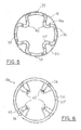
- Fig. 5 shows an embodiment of insulating element 18d formed with projections 40 extending inwardly. Portions 39 of element 18d not projecting inwardly run parallel to, and are in contact with, jacket 12 of the drum. Few spacers 36 are forced between wall 20, 20', to support the double wall structure of the insulating element.
- Fig. 6 shows an embodiment of an insulating element 18e with two parallel walls 20, 20' and spacers 36 in the evacuated space in-between.
- Cup-shaped baffles 42 preferably made of plastic material, project inwardly from wall 20', and are fixed to it by means of bolts and nuts 44, or other suitable fastening means.
- bolts 44 are located in correspondence to spacers 36, which ensure stronger support than other portions of wall 20'.
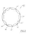
- Figure 7 shows an embodiment of an insulating element 18f with two parallel walls 20, 20' directly fixed together along longitudinal welded zone W.
- the distance between the walls 20 and 20' is kept by longitudinal grooves 48, so that no spacer is actually needed.
- the welded zone W has a reduced area in order to avoid thermal bridges.
- An improved energy efficiency of the household laundry dryer of the invention is achieved if a heating element of the air to be fed into the drum is positioned near the inlet 16 shown in Fig. 1 and 2.
- a combination of such feature with the use of a vacuum insulated drum maximises the efficiency of the dryer.
Landscapes
- Engineering & Computer Science (AREA)
- Textile Engineering (AREA)
- Detail Structures Of Washing Machines And Dryers (AREA)
Abstract
An improved household laundry dryer comprises a rotatable drum (10) with an opening (14) associated to closing means for the laundry items to be dried, an inlet (16) for drying air directed to said items to be dried, support means and driving means for said drum, and is characterized in that at least a portion of the drum (10) comprises an insulating double wall element (18) enclosing an evacuated and sealed space (30). The laundry dryer minimizes the waste of thermal energy through the walls of the drum containing the laundry items to be dried.
Description
- The present invention relates to a household laundry dryer with a thermally insulated drum.
- Household laundry dryers are not very energy efficient. A reason for energy waste is heat transfer through the walls of heated bodies due to poor thermal efficiency.
-
DE 41 04 678 A1 discloses a household laundry dryer with an improved energy efficiency achieved by shortening the path of warm air to be fed to the drum containing the laundry items to be dried. Shortening the path of warm air is in turn achieved by mounting a heating element close to a perforated portion of the drum through which heated air flows directly into the drum. This reduces the contact of warm air with parts other than the drum. -
US 5,107,649 discloses embodiments of vacuum insulation panels to be used in a variety of applications, including generally clothes dryers, with no mention to insulating rotating members of household appliances. In all cases the evacuated space between the walls of an insulated panel is filled with spacers in the form of spheres, beads or elements with other discrete shapes to provide mechanical support. Although such filling elements can be made of glass or ceramic, namely of materials that minimise thermal conductance, undesired thermal bridges between the internal and external walls of the panel still exist due to numerous points of contact through the filling elements. Therefore, a waste of energy due to significant heat transfer through the walls of heated bodies still occurs. Also, when a stream of warm air transporting water evaporated from the laundry hits the cold walls of the drum, condensation of water occurs and liquid water flows back into the laundry. - There thus exists a need for a household laundry dryer with improved energy efficiency, possibly for a household laundry dryer with Class A energy efficiency.
- It is therefore the overall object of the present invention to disclose an improved household laundry dryer capable of minimising the waste of thermal energy through the walls of the drum containing the laundry items to be dried.
- It is a further object of the present invention to disclose an improved household laundry dryer capable of minimising the waste of thermal energy with a relatively compact drum structure suitable to be adapted to the size of commercially available dryers.
- It is an additional object of the present invention to disclose an improved household laundry dryer capable of minimising the waste of thermal energy with a relatively simple drum structure, namely a structure that does not require a major increase of the manufacturing cost.
- The aforesaid and other objects of the invention, as it will appear from the following description, are achieved by an improved household laundry dryer comprising a drum with an opening associated to closing means for the laundry items to be dried, an inlet for drying air directed to said items to be dried, support means and driving means for said drum, characterised in that at least a portion of said drum comprises an insulating element having a double wall enclosing a sealed space. Such sealed space is preferably an evacuated space, i.e. with a predetermined degree of vacuum therein.
- According to another aspect of the invention, said insulating double wall extends along the entire cylindrical surface of said drum.
- According to a further aspect of the invention, spacers are positioned at discrete points in the evacuated space of said insulating double wall.
- According to a further aspect of the invention, said double wall is shaped with projections extending inwardly.
- Some embodiments of the invention will now be described by way of example with reference to the attached drawings, wherein:
- Fig. 1 is a schematic sectional view taken along the longitudinal axis Y of a first embodiment of drum of a laundry dryer according to the invention;
- Fig. 2 is a schematic sectional view taken along the longitudinal axis Y of a second embodiment of drum of a laundry dryer according to the invention;
- Fig. 3 is a schematic cross-sectional view taken along a plane perpendicular to longitudinal axis Y of a third embodiment of a drum according to the invention;
- Fig. 4 is a schematic cross-sectional view taken along a plane perpendicular to longitudinal axis Y of a fourth embodiment of a drum according to the invention;
- Fig. 5 is a schematic cross-sectional taken along a plane perpendicular to longitudinal axis Y of a fifth embodiment of a drum according to the invention;
- Fig. 6 is a schematic cross-sectional taken along a plane perpendicular to longitudinal axis Y of a sixth embodiment of a drum according to the invention; and
- Fig. 7 is a schematic cross-sectional section taken along a plane perpendicular to longitudinal axis Y of a seventh embodiment of a drum according to the present invention.
- With reference to Fig. 1, a drum of a laundry dryer is generally designated with 10.
Drum 10 comprises anexternal jacket 12 with anopening 14 for introducing the washed clothes to be dried into the dryer. Closing means associated to opening 14 are not shown since they are known to the person skilled in the art. - Also not shown are support and driving means of
drum 10 as well as the cabinet in which thedrum 10 is rotatably mounted, since they are well known to the person skilled in the art. Aninlet 16 for a flow of warm drying air heated upstream is also provided indrum 10. A double wall element for thermal insulation generally designated with 18 is mounted withinjacket 12.Wall 20 and 20' ofinsulating element 18 extend along the entire internal cylindrical surface ofjacket 12 in the proximity thereof, and are fixed tojacket 12 by means of top andbottom plates space 30 is defined betweenwalls 20, 20' to provide an effective insulation against heat transfer throughwall 20' and 20. Thespace 30 is preferably evacuated, even if the double-wall construction is already sufficient for providing a good reduction of thermal conductivity. The upper andlower portions walls 20, 20' are bent and joined to each other, to provide a tight seal and ensure that vacuum is maintained inspace 30. The degree of insulation depends on several factors, including the degree of vacuum used inspace 30. - Fig. 2 shows an embodiment of the invention in which an insulating element 18a extends along the internal cylindrical surface of
jacket 12 for a significant portion of its height, not for the entire height as in the embodiment of Fig. 1. Internal wall 20' may be formed with recesses such as 32, providing a seat for spacer tubes or bolt, as it will be illustrated in the following. Although ideally it would be desirable to have aninsulating element 18 that covers the entire surface ofjacket 12, a compromise can be found among extent of the insulation element and structure of the external jacket, manufacturing needs, and so on. - Fig. 3 and Fig. 4 show a schematic cross-sectional view of two similar embodiments of the double wall insulating element according to the invention, designated with 18b and 18c, respectively. Internal wall 20' of
element 18b is formed with fourprojections 34 directed inwardly, thereby increasing the size of the evacuatedspace 30. The function ofprojections 34 is twofold, since they constitute also baffles for the laundry items during rotation of the drum. Such baffles open and separate the laundry items, ultimately improving the drying efficiency.Spacer tubes 36 are forced betweenwall 20 and 20', to keep them spaced apart and avoid collapsing of the double wall insulating element. The number of such spacers is limited to avoid loss of insulation power due to thermal bridges. The number of spacers can be very small since the double wall insulating element of the invention exploits the "ring stability" effect of cylindrical hollow body, wherein the need for stabilisation is negligible or very limited. This makes unnecessary to fill-up the evacuated space with filling material such as glass or ceramic beads.Spacers 36 are small tubes that can engage projections formed byrecesses 32 of Fig. 2. - Fig. 4 shows a structure of an
insulating element 18c similar to the structure ofinsulating element 18b, but withmore projections 38 from the internal wall 20', such projection being directed radially inwardly to a lesser extent thanprojections 34 ofelement 18b. However, they still perform both the function of increasing the volume of the evacuatedspace 30 and the function of baffle for the laundry items during rotation. - Fig. 5 shows an embodiment of
insulating element 18d formed withprojections 40 extending inwardly.Portions 39 ofelement 18d not projecting inwardly run parallel to, and are in contact with,jacket 12 of the drum.Few spacers 36 are forced betweenwall 20, 20', to support the double wall structure of the insulating element. - Fig. 6 shows an embodiment of an insulating element 18e with two
parallel walls 20, 20' andspacers 36 in the evacuated space in-between. Cup-shaped baffles 42, preferably made of plastic material, project inwardly from wall 20', and are fixed to it by means of bolts andnuts 44, or other suitable fastening means. Advantageously,bolts 44 are located in correspondence tospacers 36, which ensure stronger support than other portions of wall 20'. - Figure 7 shows an embodiment of an insulating element 18f with two
parallel walls 20, 20' directly fixed together along longitudinal welded zone W. In this embodiment the distance between thewalls 20 and 20' is kept bylongitudinal grooves 48, so that no spacer is actually needed. Of course the welded zone W has a reduced area in order to avoid thermal bridges. - An improved energy efficiency of the household laundry dryer of the invention is achieved if a heating element of the air to be fed into the drum is positioned near the
inlet 16 shown in Fig. 1 and 2. A combination of such feature with the use of a vacuum insulated drum maximises the efficiency of the dryer. - It is clear from the description above that other embodiments of the drum of a laundry dryer with insulating double wall element according to the invention are possible within the same inventive concept.
Claims (12)
- Household laundry dryer comprising a drum (10) with an opening (14) associated to closing means for the laundry items to be dried, an inlet (16) for drying air directed to said items to be dried, support means and driving means for said drum, characterised in that at least a portion of said drum comprises an insulating double wall element (18;18a;18b;18c;18d;18e;18f) enclosing a sealed space (30).
- Household laundry dryer according to claim 1, characterised in that in the sealed space (30) there is a predetermined degree of vacuum.
- Household laundry dryer according to claim 1, characterised in that spacers (36) are positioned between the internal wall (20') and the external wall (20) of said insulating element (18a;18b;18c;18d;18e), and are not in contact with each other.
- Household laundry dryer according to claim 3, characterised in that each of said spacer (36) is in contact with said internal wall (20') and said external wall (20) of said insulating element (18a;18b;18c;18d;18e).
- Household laundry dryer according to claim 3, characterised in that each of said spacer (36) has the shape of a tube.
- Household laundry dryer according to any previous claim, characterised in that said insulating double wall element (18a;18b;18c;18d;18e) has projections directed inwardly, thereby forming baffles (34;38;40;42) to operatively open or separate the laundry items.
- Household laundry dryer according to claim 6, characterised in that said baffles are formed by projections (34;38;40) directed inwardly from said internal wall (20') of said insulating double wall element (18b;18c;18d).
- Household laundry dryer according to claim 6, characterised in that said baffles are cup-shaped elements (42) directed inwardly from said internal wall (20') of said insulating double wall element (18e).
- Household laundry dryer according to claim 8, characterised in that said baffles (42) are fixed to said insulating double wall element (18e) by fastening means located in correspondence to said spacers (36).
- Household laundry dryer according to claim 1, characterised in that said double wall element (18d) comprises projections (40) extending inwardly and portions (39) that extend parallel to, and in contact with, an external jacket (12) of said drum (10).
- Household laundry dryer according to claim 1, characterised in that said double wall element (18f) comprises an inner wall (20') having longitudinal grooves (48) fixed to an outer wall (20), the sealed space (30) being defined in zones between said longitudinal grooves (48).
- Household laundry dryer according to any previous claim, characterised in that air heating means is positioned just upstream said air inlet (16).
Priority Applications (1)
| Application Number | Priority Date | Filing Date | Title |
|---|---|---|---|
| EP06116602A EP1876283A1 (en) | 2006-07-05 | 2006-07-05 | Household laundry dryer with thermally insulated drum |
Applications Claiming Priority (1)
| Application Number | Priority Date | Filing Date | Title |
|---|---|---|---|
| EP06116602A EP1876283A1 (en) | 2006-07-05 | 2006-07-05 | Household laundry dryer with thermally insulated drum |
Publications (1)
| Publication Number | Publication Date |
|---|---|
| EP1876283A1 true EP1876283A1 (en) | 2008-01-09 |
Family
ID=37533465
Family Applications (1)
| Application Number | Title | Priority Date | Filing Date |
|---|---|---|---|
| EP06116602A Withdrawn EP1876283A1 (en) | 2006-07-05 | 2006-07-05 | Household laundry dryer with thermally insulated drum |
Country Status (1)
| Country | Link |
|---|---|
| EP (1) | EP1876283A1 (en) |
Cited By (2)
| Publication number | Priority date | Publication date | Assignee | Title |
|---|---|---|---|---|
| ITBO20090200A1 (en) * | 2009-03-30 | 2010-09-30 | I F T S R L | BASKET FOR DRYER. |
| WO2011074853A1 (en) * | 2009-12-15 | 2011-06-23 | 엘지전자 주식회사 | Laundry treating apparatus |
Citations (8)
| Publication number | Priority date | Publication date | Assignee | Title |
|---|---|---|---|---|
| DE8105912U1 (en) * | 1981-03-02 | 1981-08-06 | Bosch-Siemens Hausgeräte GmbH, 7000 Stuttgart | LAUNDRY DRYER DRUM |
| JPS5786399A (en) * | 1980-11-20 | 1982-05-29 | Hitachi Ltd | Clothing drier |
| JPH0332700A (en) * | 1989-06-30 | 1991-02-13 | Matsushita Electric Ind Co Ltd | Cloth dryer |
| JPH03103300A (en) * | 1989-09-16 | 1991-04-30 | Hitachi Ltd | Clothes dryer |
| JPH09140999A (en) * | 1995-11-22 | 1997-06-03 | Toshiba Corp | Clothes dryer |
| JPH11333199A (en) * | 1998-05-28 | 1999-12-07 | Matsushita Electric Ind Co Ltd | Clothes dryer |
| JP2000107494A (en) * | 1998-10-07 | 2000-04-18 | Hitachi Ltd | Clothes dryer |
| JP2000225298A (en) * | 1999-02-08 | 2000-08-15 | Hitachi Ltd | Clothes dryer |
-
2006
- 2006-07-05 EP EP06116602A patent/EP1876283A1/en not_active Withdrawn
Patent Citations (8)
| Publication number | Priority date | Publication date | Assignee | Title |
|---|---|---|---|---|
| JPS5786399A (en) * | 1980-11-20 | 1982-05-29 | Hitachi Ltd | Clothing drier |
| DE8105912U1 (en) * | 1981-03-02 | 1981-08-06 | Bosch-Siemens Hausgeräte GmbH, 7000 Stuttgart | LAUNDRY DRYER DRUM |
| JPH0332700A (en) * | 1989-06-30 | 1991-02-13 | Matsushita Electric Ind Co Ltd | Cloth dryer |
| JPH03103300A (en) * | 1989-09-16 | 1991-04-30 | Hitachi Ltd | Clothes dryer |
| JPH09140999A (en) * | 1995-11-22 | 1997-06-03 | Toshiba Corp | Clothes dryer |
| JPH11333199A (en) * | 1998-05-28 | 1999-12-07 | Matsushita Electric Ind Co Ltd | Clothes dryer |
| JP2000107494A (en) * | 1998-10-07 | 2000-04-18 | Hitachi Ltd | Clothes dryer |
| JP2000225298A (en) * | 1999-02-08 | 2000-08-15 | Hitachi Ltd | Clothes dryer |
Cited By (8)
| Publication number | Priority date | Publication date | Assignee | Title |
|---|---|---|---|---|
| ITBO20090200A1 (en) * | 2009-03-30 | 2010-09-30 | I F T S R L | BASKET FOR DRYER. |
| WO2011074853A1 (en) * | 2009-12-15 | 2011-06-23 | 엘지전자 주식회사 | Laundry treating apparatus |
| US10400384B2 (en) | 2009-12-15 | 2019-09-03 | Lg Electronics Inc. | Laundry treating apparatus |
| US12091808B2 (en) | 2009-12-15 | 2024-09-17 | Lg Electronics Inc. | Laundry treating apparatus |
| US12351975B2 (en) | 2009-12-15 | 2025-07-08 | Lg Electronics Inc. | Laundry treating apparatus |
| US12454787B2 (en) | 2009-12-15 | 2025-10-28 | Lg Electronics Inc. | Laundry treating apparatus |
| US12590401B2 (en) | 2009-12-15 | 2026-03-31 | Lg Electronics Inc. | Laundry treating apparatus |
| US12595618B2 (en) | 2009-12-15 | 2026-04-07 | Lg Electronics Inc. | Laundry treating apparatus |
Similar Documents
| Publication | Publication Date | Title |
|---|---|---|
| RU2404702C2 (en) | Dishwashing machine with sorption drying device | |
| US8978638B2 (en) | Door with a built-in burner for a heating appliance | |
| KR100337751B1 (en) | Heat and cold machine | |
| CN107289431A (en) | Steam generator and dish-washing machine | |
| CN110081588A (en) | Gas heater | |
| JPH05126479A (en) | Rotary type heat exchanger | |
| KR200429044Y1 (en) | Commercial large pot | |
| CN104023613A (en) | Heating device in a water-bearing domestic appliance | |
| KR20000056978A (en) | Elliptical Heat Pipe with Carbon Steel Fins and Bonded with Zinc Galvanizing | |
| AU784851B2 (en) | Electrical heater | |
| CN221069437U (en) | Wave-proof plate, storage tank and tank container | |
| KR100815719B1 (en) | Vertical electric boiler. | |
| CN206371863U (en) | Electric pressure cooker | |
| KR100636892B1 (en) | dryer | |
| KR200194949Y1 (en) | Corrugated Tube Heat Pipe, Heat Exchanger | |
| KR200215784Y1 (en) | Heating system for Boiler | |
| CN222256476U (en) | Tubular steam electric heating body and instant heating type steam generating device | |
| CN220937735U (en) | Oven liner and oven | |
| CN220304239U (en) | Hot furnace body | |
| CN105276970A (en) | Rotating type vacuum heat conduction and exchange device | |
| JPS6020964Y2 (en) | Even heating container | |
| KR200265837Y1 (en) | Heat accumulating device using a phase change material | |
| CN212326139U (en) | a rice cooker | |
| KR100876453B1 (en) | Heat pipe | |
| KR20010049203A (en) | Spiral corrugated tube heat pipes, heat exchanger. |
Legal Events
| Date | Code | Title | Description |
|---|---|---|---|
| PUAI | Public reference made under article 153(3) epc to a published international application that has entered the european phase |
Free format text: ORIGINAL CODE: 0009012 |
|
| AK | Designated contracting states |
Kind code of ref document: A1 Designated state(s): AT BE BG CH CY CZ DE DK EE ES FI FR GB GR HU IE IS IT LI LT LU LV MC NL PL PT RO SE SI SK TR |
|
| AX | Request for extension of the european patent |
Extension state: AL BA HR MK YU |
|
| AKX | Designation fees paid | ||
| REG | Reference to a national code |
Ref country code: DE Ref legal event code: 8566 |
|
| STAA | Information on the status of an ep patent application or granted ep patent |
Free format text: STATUS: THE APPLICATION IS DEEMED TO BE WITHDRAWN |
|
| 18D | Application deemed to be withdrawn |
Effective date: 20080710 |