EP1874672B1 - Equine training aid - Google Patents
Equine training aid Download PDFInfo
- Publication number
- EP1874672B1 EP1874672B1 EP06726848.2A EP06726848A EP1874672B1 EP 1874672 B1 EP1874672 B1 EP 1874672B1 EP 06726848 A EP06726848 A EP 06726848A EP 1874672 B1 EP1874672 B1 EP 1874672B1
- Authority
- EP
- European Patent Office
- Prior art keywords
- continuous loop
- equine
- horse
- loop portion
- training
- Prior art date
- Legal status (The legal status is an assumption and is not a legal conclusion. Google has not performed a legal analysis and makes no representation as to the accuracy of the status listed.)
- Expired - Lifetime
Links
Images

Classifications
-
- B—PERFORMING OPERATIONS; TRANSPORTING
- B68—SADDLERY; UPHOLSTERY
- B68B—HARNESS; DEVICES USED IN CONNECTION THEREWITH; WHIPS OR THE LIKE
- B68B1/00—Devices in connection with harness, for hitching, reining, training, breaking or quietening horses or other traction animals
-
- B—PERFORMING OPERATIONS; TRANSPORTING
- B68—SADDLERY; UPHOLSTERY
- B68B—HARNESS; DEVICES USED IN CONNECTION THEREWITH; WHIPS OR THE LIKE
- B68B1/00—Devices in connection with harness, for hitching, reining, training, breaking or quietening horses or other traction animals
- B68B1/04—Bridles; Reins
Definitions
- the invention relates to an equine training aid for enabling a horse, pony, donkey or the like, particularly dressage or show horses, to adopt an optimum outline or profile.
- equine training aid of the present invention is equally applicable to horses, ponies and the like and references made herein to horses extend equally to other equine animals such as ponies, donkeys and the like.
- One factor in measuring penalty points involves assessing the outline or profile which the horse adopts.
- One such outline or profile is known as "Topline", which is the shape that the horse makes from the top of its neck (poll) to the tail.
- Topline is the shape that the horse makes from the top of its neck (poll) to the tail.
- flexion a bending movement
- a number of training aid devices are available which aim to develop or train a horse to allow it to adopt the optimum topline profile.
- the known devices are fixed in position and thereby function to force the horse to develop the required outline. This is clearly not desirable because such an arrangement can often cause stress and pain to the animal.
- Another drawback with the existing training aids is that they focus only on training the front end of the horse (the fore quarters) rather than both the fore and hind quarters. This is clearly undesirable because the horse generates power through the hind quarters and is therefore an important target for training.
- One further drawback with existing training aids is the requirement for rider operation by means of a separate rein whilst riding the horse which is also clearly undesirable because such an arrangement would result in complicated co-ordination of riding and training.
- a yet further drawback with existing training aids is the use of a complex system of pulleys which are not only complicated to fit but also require numerous adjustments, particularly when direction changes are required. There is thus a great need for an effective horse training aid which does not cause stress or pain to the horse and is simple to fit and use.
- FR2 449 646 discloses a training aid for horses comprising elastic belts of sufficient length to go around the animal, from the jaw, along each side of the neck, the sides and behind the thighs and a means for maintaining the aid in position.
- FR 2 778 906 discloses reins consisting of an elastic strap (5) passing through pulleys (2, 3) on either end of the bit and an additional central pulley (4) connected to a harness comprising neck (7, 8) and chest (9) straps.
- the free ends of the elastic strap are attached to the reins (11) or connecting straps (12) e.g. for a lunging rein.
- the neck straps are also of an elastic material.
- US 4 453 371 discloses a harness for a horse comprising leash means having a first portion and a second portion, (a) said first portion being forked to provide first and second side leashes each having end portions, (b) and second portion being a portion selected from the alternative portions: (i) a portion positionable under said horse and fastenable to the horse's tail, (ii) a portion positionable under said horse and fastenable to a girth for said horse, and (iii) a portion positionable at a front portion of said horse and fastenable to means carried by that front portion; first support means fastenable to bridle means such that said first side leash will be supported by said first support means so as to be running movable relative to said bridle means; and second support means fastenable to said bridle means such that said second side leash will be supported by said second support means so as to be running movable relative to said bridle means.
- the continuous loop portion encourages the horse to adopt the desired topline profile, rather than physically forcing it to do so.
- the device works in such a manner because the horse prefers to reduce the tension between itself and the loop and moves of its own accord to minimise any such tension.
- the horse consequently chooses to position itself such that the continuous loop is at contact tension, and willingly assumes an optimum topline profile rather than actively being forced into such an outline.
- the invention is therefore an effective training aid, which also provides a comfortable environment within which the horse can move, and as such, is an animal friendly and holistic approach to horse training, as opposed to previously known devices.
- training method of the present invention may be used during lungeing or riding.
- the continuous loop would generally pass, in use, substantially horizontally around the body of the horse, preferably from the head to the hindquarters.
- Such an embodiment will allow the forequarter and hindquarter muscles of the horse to be trained to achieve an optimum outline or profile.
- the continuous loop portion may comprise one or more sections linked by joining means while still retaining the configuration of a continuous loop.
- the advantage of such an arrangement is that the loop can be fitted around the horse and removed easily. Furthermore, in the lungeing embodiment, this allows the rear part of the loop portion to drop below the level of the front part of the loop portion without losing contact tension.
- the joining means comprise a ring on one part which may be joined together by means of any suitable clips on the other part which may easily be attached and released, for example, a pivotal or swivel clip.
- the continuous loop would generally pass, in use, substantially from behind the ears (the poll) of the horse or the crest of the neck of the horse through the bit ring.
- Such an embodiment will allow the neck muscles to be trained to achieve an optimum outline or profile.
- the method comprises arranging more than one self-centring, continuous loop portions (preferably two), one of which is arranged, in use, to pass substantially horizontally around the body of the horse and the other of which is arranged, in use, to pass substantially from behind the ears (the poll) of the horse or the crest of the neck of the horse through the bit ring.
- arranging more than one self-centring, continuous loop portions preferably two
- one of which is arranged, in use to pass substantially horizontally around the body of the horse and the other of which is arranged, in use, to pass substantially from behind the ears (the poll) of the horse or the crest of the neck of the horse through the bit ring.
- the continuous loop portion is arranged such that it is held in place during lungeing or riding by a connecting portion passing between the forelegs linking the loop portion to a girth or lungeing roller.
- the connecting portion may be thought of as guides for the continuous loop rather than one or more anchors for the loop; the continuous loop is still free to rotate to a limited extent in a longitudinal manner relative to the horse.
- the continuous loop portion can be connected to the connecting portion by a variety of means, for example, a ring or a pivotal or swivel clip.
- the continuous loop portion and connecting portion comprise one or more adjustment means to enable each portion to be lengthened or shortened to fit a variety of different sized horses and also to allow adjustment to the desired horse outline or profile.
- the adjustment means comprise a buckle or slider, although any suitable device is possible.
- the continuous loop portion may also during lungeing or riding, be connected with or pass through one or more supporting means provided at one or more locations about the body of the horse.
- supporting means include the bit ring and the lungeing or breaking roller. These supporting means function solely to hold the continuous loop in place, for example, in the lungeing embodiment, the method preferably comprises passing the continuous loop through the 'D' rings of the lungeing roller to stop the loop from sliding down the hindquarters of the horse.
- the supporting means may be thought of as guides for the continuous loop rather than an anchor for the loop; the continuous loop is still free to rotate to a limited extent in a longitudinal manner relative to the horse through the supporting means.
- the continuous loop portion and connecting portion are constructed from natural materials such as leather or modem synthetic materials such as nylon. It will be appreciated that synthetic materials are more preferable as these are lightweight, easy to clean and less abrasive at points of contact on the horse.
- an equine training aid comprising a continuous loop portion, configured, when in use, to be in contact tension with the horse.
- an equine training aid comprising a continuous loop portion, configured, during lungeing or riding, to be in contact tension with the horse.
- the equine training aid may additionally comprise a safety loop.
- the safety loop is advantageously located at both ends of the rear section of the continuous loop portion and is configured to prevent the rear section slipping down the hind legs of the horse when the device is being dismantled and removed from the horse. In the absence of such a safety loop, dismantling the device would cause it to suddenly drop, which could potentially startle the horse.
- the presence of the safety loop ensures that the front section of the device can be removed first while the rear section remains in place.
- the safety loop additionally provides the advantage of allowing rotation of the continuous loop to a limited extent during use (e.g. during lungeing).
- a continuous loop portion shown generally as 1 comprises a front section 1a and a rear section 1b which are linked by linking means in the form of rings 2a and pivotal clips 2b such that the overall configuration is a continuous loop.
- Each of the loop sections 1a and 1b additionally has two adjustment means (e.g. sliders) 3 to allow each loop section to be lengthened or shortened.
- Both ends of the rear section 1b terminate in a safety loop 4 which allows rotation of the device to a limited extent and prevents the rear section of the loop portion 1b from slipping down the hind legs of the horse when the front section 1a of the continuous loop portion 1 is dismantled and removed from the horse.
- An additional continuous loop portion is shown in Figure 2 as 100 and comprises two sections 1c linked together at one end by a ring 15. Both of the other ends of sections 1c are connected by pivotal clips 2b to two rings 2a on an additional section 1d. Each of the sections 1c additionally has two adjustment means (e.g. sliders) 3 to allow the loop section 100 to be lengthened or shortened.
- the additional section 1d comprises a clip 19 for attachment of the continuous loop portion 100 to the connecting portion discussed in Figure 3 .
- a connecting portion is shown generally as 5 and comprises a single section 5a with adjustment means (e.g. a buckle) 6 to allow the connecting portion 5 to be lengthened or shortened.
- the connecting section 5a is attached to a flattened loop section 7 at one end by a D shaped ring 2a and pivotal clip 2b and is connected at the other end to a ring 8.
- Figure 4 shows a horse wearing a conventional snaffle bridle 12 fitted around the head of the horse and connected to a bit ring 9.
- the continuous loop portion 1 described in Figure 1 passes substantially horizontally around the body of the horse.
- the rear section 1b of the continuous loop portion 1 passes through the D-ring 10 of the lungeing roller 11 and the safety loop 4 passes over the D-ring 10 and attaches, for example, to ring 2a of the rear section 1b to allow rotation of the continuous loop portion to a limited extent during use and to prevent the rear section of the loop portion 1b from slipping down the hind legs of the horse when the front section 1a of the continuous loop portion 1 is dismantled and removed from the horse.
- Figure 6 A more detailed view of the interaction between the rear section 1b of the continuous loop portion 1 and the D-ring 10 of the lungeing roller 11 is shown in Figure 6 .
- the front section 1a of the continuous loop portion 1 passes through both bit rings 9 of the horse (only one is shown in Figures) and passes through the ring 8 of the connecting portion 5.
- This connecting portion 5 passes between the forelegs of the horse and is linked to the lungeing roller 11 by the flattened loop section 7.
- Figure 5A shows a horse wearing a conventional snaffle bridle 12 fitted around the head of the horse and reins 13, both of which are connected to both bit rings 9 (only one is shown in Figures).
- the continuous loop portion 100 described in Figure 2 passes substantially from the crest of the neck of the horse (shown in Figure 5A by the ring 15) and passes through both bit rings 9 and is connected to the ring 8 of the connecting portion 5 described in Figure 3 by the clip 19 as described in Figure 2 .
- the connecting portion 5 passes between the forelegs of the horse and is linked to the girth 14 by the flattened loop section 7.
- the presence of the additional section 1d allows self-centring and rotation of the continuous loop portion 100 to a limited extent during use. For example, movement of the continuous loop portion is allowed by the additional section 1d but is restricted and centred by the presence of the rings 2a and the connecting portion 5.
- Figure 5B demonstrates how the continuous loop portion 100 passes through the bit ring 9 of the snaffle bridle 12.
Landscapes
- Engineering & Computer Science (AREA)
- Mechanical Engineering (AREA)
- Rehabilitation Tools (AREA)
- Orthopedics, Nursing, And Contraception (AREA)
Description
- The invention relates to an equine training aid for enabling a horse, pony, donkey or the like, particularly dressage or show horses, to adopt an optimum outline or profile.
- It will be appreciated that the equine training aid of the present invention is equally applicable to horses, ponies and the like and references made herein to horses extend equally to other equine animals such as ponies, donkeys and the like.
- According to the Federation Equestre Internationale, there are over 12 million horses owned worldwide and 27 million people ride regularly. According to American Horse Council statistics, there are 6.9 million horses in the United States of America, including both commercial and recreational horses. Almost 3 million of these are owned purely for showing and recreational purposes, and approximately 4.5 million people actively participate in showing and related recreational activities.
- During events involving horses, such as dressage events, success is measured by gaining the fewest penalty points. One factor in measuring penalty points involves assessing the outline or profile which the horse adopts. One such outline or profile is known as "Topline", which is the shape that the horse makes from the top of its neck (poll) to the tail. However, not all horses move in the correct outline and accept instructions through the rider's hand and/or have flexion (a bending movement) through the poll. Thus, for a horse to be successful in dressage events it must be trained to adopt an optimum outline or profile.
- A number of training aid devices are available which aim to develop or train a horse to allow it to adopt the optimum topline profile. However, there are numerous drawbacks with such devices. For example, the known devices are fixed in position and thereby function to force the horse to develop the required outline. This is clearly not desirable because such an arrangement can often cause stress and pain to the animal. Another drawback with the existing training aids is that they focus only on training the front end of the horse (the fore quarters) rather than both the fore and hind quarters. This is clearly undesirable because the horse generates power through the hind quarters and is therefore an important target for training. One further drawback with existing training aids is the requirement for rider operation by means of a separate rein whilst riding the horse which is also clearly undesirable because such an arrangement would result in complicated co-ordination of riding and training. A yet further drawback with existing training aids is the use of a complex system of pulleys which are not only complicated to fit but also require numerous adjustments, particularly when direction changes are required. There is thus a great need for an effective horse training aid which does not cause stress or pain to the horse and is simple to fit and use.
-
FR2 449 646 -
FR 2 778 906 -
US 4 453 371 discloses a harness for a horse comprising leash means having a first portion and a second portion, (a) said first portion being forked to provide first and second side leashes each having end portions, (b) and second portion being a portion selected from the alternative portions: (i) a portion positionable under said horse and fastenable to the horse's tail, (ii) a portion positionable under said horse and fastenable to a girth for said horse, and (iii) a portion positionable at a front portion of said horse and fastenable to means carried by that front portion; first support means fastenable to bridle means such that said first side leash will be supported by said first support means so as to be running movable relative to said bridle means; and second support means fastenable to said bridle means such that said second side leash will be supported by said second support means so as to be running movable relative to said bridle means. - According to the invention there is provided a method of training an equine in accordance with
claim 1. - It is believed that a horse within a continuous loop psychologically likes to reduce tension between itself and the loop and therefore tends to position itself to minimise tension within the loop. Although the loop is held in place around the horse it is able to rotate to a limited extent in a longitudinal manner relative to the horse, which allows it to be self- centring. Thus, the loop is not attached to the horse in a manner that prevents rotation thereof.
- For the purposes of the invention 'contact tension' should be understood as being achieved when neither pulling nor sagging of the continuous loop occurs.
- When in use, the continuous loop portion encourages the horse to adopt the desired topline profile, rather than physically forcing it to do so. The device works in such a manner because the horse prefers to reduce the tension between itself and the loop and moves of its own accord to minimise any such tension. The horse consequently chooses to position itself such that the continuous loop is at contact tension, and willingly assumes an optimum topline profile rather than actively being forced into such an outline. The invention is therefore an effective training aid, which also provides a comfortable environment within which the horse can move, and as such, is an animal friendly and holistic approach to horse training, as opposed to previously known devices.
- It will be appreciated that the training method of the present invention may be used during lungeing or riding.
- In the lungeing embodiment, the continuous loop would generally pass, in use, substantially horizontally around the body of the horse, preferably from the head to the hindquarters. Such an embodiment will allow the forequarter and hindquarter muscles of the horse to be trained to achieve an optimum outline or profile.
- It will be appreciated that the continuous loop portion may comprise one or more sections linked by joining means while still retaining the configuration of a continuous loop. The advantage of such an arrangement is that the loop can be fitted around the horse and removed easily. Furthermore, in the lungeing embodiment, this allows the rear part of the loop portion to drop below the level of the front part of the loop portion without losing contact tension. Preferably, the joining means comprise a ring on one part which may be joined together by means of any suitable clips on the other part which may easily be attached and released, for example, a pivotal or swivel clip.
- In the riding embodiment, the continuous loop would generally pass, in use, substantially from behind the ears (the poll) of the horse or the crest of the neck of the horse through the bit ring. Such an embodiment will allow the neck muscles to be trained to achieve an optimum outline or profile.
- In a further embodiment, the method comprises arranging more than one self-centring, continuous loop portions (preferably two), one of which is arranged, in use, to pass substantially horizontally around the body of the horse and the other of which is arranged, in use, to pass substantially from behind the ears (the poll) of the horse or the crest of the neck of the horse through the bit ring. Such an embodiment will allow the neck, forequarter and hindquarter muscles of a horse to be trained to achieve an optimum outline or profile.
- The continuous loop portion is arranged such that it is held in place during lungeing or riding by a connecting portion passing between the forelegs linking the loop portion to a girth or lungeing roller. The connecting portion may be thought of as guides for the continuous loop rather than one or more anchors for the loop; the continuous loop is still free to rotate to a limited extent in a longitudinal manner relative to the horse. The continuous loop portion can be connected to the connecting portion by a variety of means, for example, a ring or a pivotal or swivel clip.
- The continuous loop portion and connecting portion comprise one or more adjustment means to enable each portion to be lengthened or shortened to fit a variety of different sized horses and also to allow adjustment to the desired horse outline or profile. Suitably, the adjustment means comprise a buckle or slider, although any suitable device is possible.
- In a further embodiment, the continuous loop portion may also during lungeing or riding, be connected with or pass through one or more supporting means provided at one or more locations about the body of the horse. Examples of such supporting means include the bit ring and the lungeing or breaking roller. These supporting means function solely to hold the continuous loop in place, for example, in the lungeing embodiment, the method preferably comprises passing the continuous loop through the 'D' rings of the lungeing roller to stop the loop from sliding down the hindquarters of the horse. As with the connecting portion, the supporting means may be thought of as guides for the continuous loop rather than an anchor for the loop; the continuous loop is still free to rotate to a limited extent in a longitudinal manner relative to the horse through the supporting means.
- In a further embodiment the continuous loop portion and connecting portion are constructed from natural materials such as leather or modem synthetic materials such as nylon. It will be appreciated that synthetic materials are more preferable as these are lightweight, easy to clean and less abrasive at points of contact on the horse.
- Also disclosed is an equine training aid comprising a continuous loop portion, configured, when in use, to be in contact tension with the horse.
- Also disclosed is an equine training aid comprising a continuous loop portion, configured, during lungeing or riding, to be in contact tension with the horse.
- The equine training aid may additionally comprise a safety loop. The safety loop is advantageously located at both ends of the rear section of the continuous loop portion and is configured to prevent the rear section slipping down the hind legs of the horse when the device is being dismantled and removed from the horse. In the absence of such a safety loop, dismantling the device would cause it to suddenly drop, which could potentially startle the horse. The presence of the safety loop ensures that the front section of the device can be removed first while the rear section remains in place. The safety loop additionally provides the advantage of allowing rotation of the continuous loop to a limited extent during use (e.g. during lungeing).
- The invention will now be described, by way of example only, with reference to the accompanying drawings in which
-
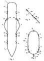
Figure 1 shows a plan view of the continuous loop portion of the invention which in use passes substantially horizontally around the body. -
Figure 2 shows a plan view of the continuous loop portion of the invention which in use passes substantially from the crest of the neck of the horse through the bit ring. -
Figure 3 shows a plan view of the connecting portion of the invention. -
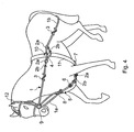
Figure 4 shows a plan view of the portions shown inFigures 1 and 3 fitted to a horse in the lungeing embodiment of the invention. -
Figure 5A shows a plan view of the portions shown inFigures 2 and 3 fitted to a horse in the riding embodiment of the invention. -
Figure 5B shows a detailed view of the interaction of the continuous loop portion and snaffle bridle shown inFigure 5A . -
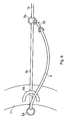
Figure 6 shows a detailed view of the interaction of the safety loop, the continuous loop portion and the D-ring of the lungeing roller shown inFigure 4 . - Referring first to
Figure 1 , a continuous loop portion shown generally as 1, comprises afront section 1a and arear section 1b which are linked by linking means in the form ofrings 2a andpivotal clips 2b such that the overall configuration is a continuous loop. Each of theloop sections rear section 1b terminate in asafety loop 4 which allows rotation of the device to a limited extent and prevents the rear section of theloop portion 1b from slipping down the hind legs of the horse when thefront section 1a of thecontinuous loop portion 1 is dismantled and removed from the horse. - An additional continuous loop portion is shown in
Figure 2 as 100 and comprises twosections 1c linked together at one end by aring 15. Both of the other ends ofsections 1c are connected bypivotal clips 2b to tworings 2a on anadditional section 1d. Each of thesections 1c additionally has two adjustment means (e.g. sliders) 3 to allow theloop section 100 to be lengthened or shortened. Theadditional section 1d comprises aclip 19 for attachment of thecontinuous loop portion 100 to the connecting portion discussed inFigure 3 . - In
Figure 3 , a connecting portion is shown generally as 5 and comprises asingle section 5a with adjustment means (e.g. a buckle) 6 to allow the connectingportion 5 to be lengthened or shortened. The connectingsection 5a is attached to a flattenedloop section 7 at one end by a D shapedring 2a andpivotal clip 2b and is connected at the other end to aring 8. - In use, during lungeing for example,
Figure 4 shows a horse wearing aconventional snaffle bridle 12 fitted around the head of the horse and connected to abit ring 9. Thecontinuous loop portion 1 described inFigure 1 passes substantially horizontally around the body of the horse. Therear section 1b of thecontinuous loop portion 1 passes through the D-ring 10 of thelungeing roller 11 and thesafety loop 4 passes over the D-ring 10 and attaches, for example, to ring 2a of therear section 1b to allow rotation of the continuous loop portion to a limited extent during use and to prevent the rear section of theloop portion 1b from slipping down the hind legs of the horse when thefront section 1a of thecontinuous loop portion 1 is dismantled and removed from the horse. A more detailed view of the interaction between therear section 1b of thecontinuous loop portion 1 and the D-ring 10 of thelungeing roller 11 is shown inFigure 6 . - The
front section 1a of thecontinuous loop portion 1 passes through both bit rings 9 of the horse (only one is shown in Figures) and passes through thering 8 of the connectingportion 5. This connectingportion 5 passes between the forelegs of the horse and is linked to thelungeing roller 11 by the flattenedloop section 7. - In use, during riding for example,
Figure 5A shows a horse wearing aconventional snaffle bridle 12 fitted around the head of the horse andreins 13, both of which are connected to both bit rings 9 (only one is shown in Figures). Thecontinuous loop portion 100 described inFigure 2 passes substantially from the crest of the neck of the horse (shown inFigure 5A by the ring 15) and passes through both bit rings 9 and is connected to thering 8 of the connectingportion 5 described inFigure 3 by theclip 19 as described inFigure 2 . The connectingportion 5 passes between the forelegs of the horse and is linked to thegirth 14 by the flattenedloop section 7. The presence of theadditional section 1d allows self-centring and rotation of thecontinuous loop portion 100 to a limited extent during use. For example, movement of the continuous loop portion is allowed by theadditional section 1d but is restricted and centred by the presence of therings 2a and the connectingportion 5. -
Figure 5B demonstrates how thecontinuous loop portion 100 passes through thebit ring 9 of thesnaffle bridle 12.
Claims (5)
- A method of training an equine to adopt a topline profile during lungeing or riding comprising arranging a continuous loop portion (1, 100) around the equine the continuous loop portion (1, 100) and the connecting portion (5) comprising one or more adjustment means (3, 6) to enable each portion (1, 5) to be lengthened or shortened to allow adjustment so neither pulling nor sagging of the continuous loop (1, 100) occurs, and adjusting the continuous loop portion (1, 100) and the connecting portion (5) so neither pulling nor sagging of the continuous loop (1, 100) occurs, wherein the loop portion (1, 100) connects with or passes through bit rings (9) characterised in that, the continuous loop portion (1, 100) configured to be free to rotate to a limited extent around the body of the equine and is held in place by a connecting portion (5) passing between the forelegs linking the loop portion (1, 100) to a girth (14) or lungeing roller (11) and so that the equine adopts an optimum topline profile.
- A method of training an equine according to claim 1 comprising passing the continuous loop portion (1) substantially horizontally around the body of the equine from the head to the hindquarters connecting with or passing through one or more supporting means provided at one or more sites around the body of an equine.
- A method of training an equine according to claim 1, comprising passing the continuous loop portion (1) substantially from behind the ears of the equine or the crest of the neck of the equine.
- A method of training an equine according to claim 1 comprising passing the continuous loop portion (1) through the 'D' rings (10) of a lungeing roller (11).
- A method of training an equine according to claim 2 wherein the continuous loop portion (1) comprises one or more sections (1a, 1b) linked by joining means (2a, 2b), said one or more sections (1a, 1b) interacting with the one or more supporting means allowing free rotation of the continuous loop portion (1) to a limited extent.
Applications Claiming Priority (2)
| Application Number | Priority Date | Filing Date | Title |
|---|---|---|---|
| GBGB0508223.5A GB0508223D0 (en) | 2005-04-23 | 2005-04-23 | Equine training aid |
| PCT/GB2006/001458 WO2006114584A1 (en) | 2005-04-23 | 2006-04-24 | Equine training aid |
Publications (2)
| Publication Number | Publication Date |
|---|---|
| EP1874672A1 EP1874672A1 (en) | 2008-01-09 |
| EP1874672B1 true EP1874672B1 (en) | 2013-11-06 |
Family
ID=34639997
Family Applications (1)
| Application Number | Title | Priority Date | Filing Date |
|---|---|---|---|
| EP06726848.2A Expired - Lifetime EP1874672B1 (en) | 2005-04-23 | 2006-04-24 | Equine training aid |
Country Status (4)
| Country | Link |
|---|---|
| US (1) | US7992368B2 (en) |
| EP (1) | EP1874672B1 (en) |
| GB (2) | GB0508223D0 (en) |
| WO (1) | WO2006114584A1 (en) |
Families Citing this family (11)
| Publication number | Priority date | Publication date | Assignee | Title |
|---|---|---|---|---|
| CA2685782A1 (en) * | 2008-11-18 | 2010-05-18 | Jason Elliott Horgan | Motion control harness for a medium to very large dog |
| US8171892B1 (en) | 2008-11-18 | 2012-05-08 | Jason Horgan | Motion control harness for a medium to large dog |
| US7963256B1 (en) * | 2008-11-18 | 2011-06-21 | Jason Horgan | Motion control harness for a medium to large dog |
| US8429884B2 (en) * | 2008-11-28 | 2013-04-30 | David Roberts | Equine training device |
| US20150307343A1 (en) * | 2014-04-23 | 2015-10-29 | Christine Daly | Equine Side Protective Device |
| WO2016071445A1 (en) * | 2014-11-06 | 2016-05-12 | O'keeffe Timothy | A horse training aid |
| EP3263515A1 (en) * | 2016-06-29 | 2018-01-03 | Ikonic Saddlery | Saddle girth |
| US10696538B2 (en) | 2017-12-15 | 2020-06-30 | Crystal Lynn Nelson | Horse training aid |
| FR3108600B1 (en) * | 2020-03-27 | 2022-02-25 | Roche Pierre Louis | Training aid for horses in two separate parts |
| US20250128933A1 (en) * | 2023-10-22 | 2025-04-24 | Jean Philippe Giacomini | Sliding Martingale |
| US20250296830A1 (en) * | 2024-03-25 | 2025-09-25 | Sarah Kearvell | Training aid for a horse |
Family Cites Families (10)
| Publication number | Priority date | Publication date | Assignee | Title |
|---|---|---|---|---|
| US378153A (en) * | 1888-02-21 | Harness | ||
| US815164A (en) * | 1904-06-24 | 1906-03-13 | William E Hayner | Halter. |
| GB1526032A (en) | 1977-07-06 | 1978-09-27 | Abbot Davies T | Harness for a horse |
| FR2449646A1 (en) | 1979-02-22 | 1980-09-19 | Blin Bernard | Horse breaking-in rein set - comprises partly elastic straps running from mouth along flanks and round withers |
| FR2709301B1 (en) | 1993-08-24 | 1995-11-17 | Michel Raffit | Gymnastic and driving harness equipment. |
| US5755185A (en) * | 1997-01-17 | 1998-05-26 | Gallagher; Vernon Ray | Training harness |
| FR2778906B1 (en) | 1998-05-20 | 2000-08-25 | Laurent Morali | ELASTIC RESTRAINT (S) AND PULLEYS |
| US6789378B1 (en) | 2002-04-10 | 2004-09-14 | David Nelson | Training device |
| US6769235B1 (en) * | 2003-03-08 | 2004-08-03 | Barry D. Hayes | Animal training system |
| DE202004004443U1 (en) | 2004-03-22 | 2004-08-19 | Szewczyk, Andrzej | Training system for horses has three rings fixedly mounted on lunging strap and further ring movable at distance from top ring and with rope running from one side to another behind back of horse |
-
2005
- 2005-04-23 GB GBGB0508223.5A patent/GB0508223D0/en not_active Ceased
-
2006
- 2006-04-23 US US11/912,201 patent/US7992368B2/en active Active
- 2006-04-24 WO PCT/GB2006/001458 patent/WO2006114584A1/en not_active Ceased
- 2006-04-24 EP EP06726848.2A patent/EP1874672B1/en not_active Expired - Lifetime
- 2006-04-24 GB GB0722108A patent/GB2440090B/en not_active Expired - Lifetime
Also Published As
| Publication number | Publication date |
|---|---|
| GB0722108D0 (en) | 2007-12-19 |
| GB0508223D0 (en) | 2005-06-01 |
| US20080250761A1 (en) | 2008-10-16 |
| WO2006114584A1 (en) | 2006-11-02 |
| EP1874672A1 (en) | 2008-01-09 |
| US7992368B2 (en) | 2011-08-09 |
| GB2440090B (en) | 2009-11-25 |
| GB2440090A (en) | 2008-01-16 |
Similar Documents
| Publication | Publication Date | Title |
|---|---|---|
| US8869750B2 (en) | Animal training apparatus | |
| US8516978B2 (en) | Animal restraint system | |
| US8561577B1 (en) | Adjustable dog harness adapted for pulling, walking, vehicle restraint and other diverse applications | |
| US20200329676A1 (en) | Compactable pet leash and harness | |
| WO2017160504A1 (en) | Three point control harness | |
| US6591589B2 (en) | Bitless bridle for governing horses and other animals | |
| US7992368B2 (en) | Equine training device | |
| US20170311572A1 (en) | Pressure distribution element holding a ring for chest harnesses | |
| US6612265B1 (en) | Safety harness for transporting and training large animals | |
| EP1117614B1 (en) | Controlling halter for animals | |
| AU672510B2 (en) | Gymnastic harnessing and guiding apparatus for a horse | |
| US9456586B1 (en) | Animal training harness | |
| US7249447B2 (en) | Horse training assembly | |
| US10696538B2 (en) | Horse training aid | |
| US4453371A (en) | Harness for a horse | |
| US11897755B2 (en) | Horse-stopping apparatus | |
| US6789378B1 (en) | Training device | |
| WO2012069469A1 (en) | An equine training device | |
| US4864804A (en) | Training hopple for trotting horses | |
| US20140109530A1 (en) | Longeing Device | |
| BE1010767A6 (en) | Elasticated harness etc for a horse | |
| US20170320722A1 (en) | Horse training aid | |
| GB2523409A (en) | Balanced support equestrian rein aid | |
| BE1011586A6 (en) | Flexible harness etc for a horse | |
| AU2288299A (en) | Equestrian control aid |
Legal Events
| Date | Code | Title | Description |
|---|---|---|---|
| PUAI | Public reference made under article 153(3) epc to a published international application that has entered the european phase |
Free format text: ORIGINAL CODE: 0009012 |
|
| 17P | Request for examination filed |
Effective date: 20071109 |
|
| AK | Designated contracting states |
Kind code of ref document: A1 Designated state(s): AT BE BG CH CY CZ DE DK EE ES FI FR GB GR HU IE IS IT LI LT LU LV MC NL PL PT RO SE SI SK TR |
|
| DAX | Request for extension of the european patent (deleted) | ||
| 17Q | First examination report despatched |
Effective date: 20111223 |
|
| GRAP | Despatch of communication of intention to grant a patent |
Free format text: ORIGINAL CODE: EPIDOSNIGR1 |
|
| INTG | Intention to grant announced |
Effective date: 20130429 |
|
| RBV | Designated contracting states (corrected) |
Designated state(s): AT BE BG CH CY CZ DE DK EE ES FI FR GR HU IE IS IT LI LT LU LV MC NL PL PT RO SE SI SK TR |
|
| GRAS | Grant fee paid |
Free format text: ORIGINAL CODE: EPIDOSNIGR3 |
|
| RIN1 | Information on inventor provided before grant (corrected) |
Inventor name: BENTLEY, HILARY ELIZABETH |
|
| GRAA | (expected) grant |
Free format text: ORIGINAL CODE: 0009210 |
|
| RAP1 | Party data changed (applicant data changed or rights of an application transferred) |
Owner name: THE UNIVERSITY OF WOLVERHAMPTON |
|
| AK | Designated contracting states |
Kind code of ref document: B1 Designated state(s): AT BE BG CH CY CZ DE DK EE ES FI FR GR HU IE IS IT LI LT LU LV MC NL PL PT RO SE SI SK TR |
|
| REG | Reference to a national code |
Ref country code: CH Ref legal event code: EP |
|
| REG | Reference to a national code |
Ref country code: AT Ref legal event code: REF Ref document number: 639332 Country of ref document: AT Kind code of ref document: T Effective date: 20131215 |
|
| REG | Reference to a national code |
Ref country code: IE Ref legal event code: FG4D |
|
| REG | Reference to a national code |
Ref country code: DE Ref legal event code: R096 Ref document number: 602006039115 Country of ref document: DE Effective date: 20140102 |
|
| REG | Reference to a national code |
Ref country code: NL Ref legal event code: VDEP Effective date: 20131106 |
|
| REG | Reference to a national code |
Ref country code: AT Ref legal event code: MK05 Ref document number: 639332 Country of ref document: AT Kind code of ref document: T Effective date: 20131106 |
|
| REG | Reference to a national code |
Ref country code: LT Ref legal event code: MG4D |
|
| PG25 | Lapsed in a contracting state [announced via postgrant information from national office to epo] |
Ref country code: NL Free format text: LAPSE BECAUSE OF FAILURE TO SUBMIT A TRANSLATION OF THE DESCRIPTION OR TO PAY THE FEE WITHIN THE PRESCRIBED TIME-LIMIT Effective date: 20131106 Ref country code: IS Free format text: LAPSE BECAUSE OF FAILURE TO SUBMIT A TRANSLATION OF THE DESCRIPTION OR TO PAY THE FEE WITHIN THE PRESCRIBED TIME-LIMIT Effective date: 20140306 Ref country code: LT Free format text: LAPSE BECAUSE OF FAILURE TO SUBMIT A TRANSLATION OF THE DESCRIPTION OR TO PAY THE FEE WITHIN THE PRESCRIBED TIME-LIMIT Effective date: 20131106 Ref country code: SE Free format text: LAPSE BECAUSE OF FAILURE TO SUBMIT A TRANSLATION OF THE DESCRIPTION OR TO PAY THE FEE WITHIN THE PRESCRIBED TIME-LIMIT Effective date: 20131106 Ref country code: FI Free format text: LAPSE BECAUSE OF FAILURE TO SUBMIT A TRANSLATION OF THE DESCRIPTION OR TO PAY THE FEE WITHIN THE PRESCRIBED TIME-LIMIT Effective date: 20131106 |
|
| PG25 | Lapsed in a contracting state [announced via postgrant information from national office to epo] |
Ref country code: BE Free format text: LAPSE BECAUSE OF FAILURE TO SUBMIT A TRANSLATION OF THE DESCRIPTION OR TO PAY THE FEE WITHIN THE PRESCRIBED TIME-LIMIT Effective date: 20131106 Ref country code: LV Free format text: LAPSE BECAUSE OF FAILURE TO SUBMIT A TRANSLATION OF THE DESCRIPTION OR TO PAY THE FEE WITHIN THE PRESCRIBED TIME-LIMIT Effective date: 20131106 Ref country code: ES Free format text: LAPSE BECAUSE OF FAILURE TO SUBMIT A TRANSLATION OF THE DESCRIPTION OR TO PAY THE FEE WITHIN THE PRESCRIBED TIME-LIMIT Effective date: 20131106 Ref country code: AT Free format text: LAPSE BECAUSE OF FAILURE TO SUBMIT A TRANSLATION OF THE DESCRIPTION OR TO PAY THE FEE WITHIN THE PRESCRIBED TIME-LIMIT Effective date: 20131106 |
|
| PG25 | Lapsed in a contracting state [announced via postgrant information from national office to epo] |
Ref country code: PT Free format text: LAPSE BECAUSE OF FAILURE TO SUBMIT A TRANSLATION OF THE DESCRIPTION OR TO PAY THE FEE WITHIN THE PRESCRIBED TIME-LIMIT Effective date: 20140306 |
|
| PG25 | Lapsed in a contracting state [announced via postgrant information from national office to epo] |
Ref country code: EE Free format text: LAPSE BECAUSE OF FAILURE TO SUBMIT A TRANSLATION OF THE DESCRIPTION OR TO PAY THE FEE WITHIN THE PRESCRIBED TIME-LIMIT Effective date: 20131106 |
|
| REG | Reference to a national code |
Ref country code: DE Ref legal event code: R097 Ref document number: 602006039115 Country of ref document: DE |
|
| PG25 | Lapsed in a contracting state [announced via postgrant information from national office to epo] |
Ref country code: SK Free format text: LAPSE BECAUSE OF FAILURE TO SUBMIT A TRANSLATION OF THE DESCRIPTION OR TO PAY THE FEE WITHIN THE PRESCRIBED TIME-LIMIT Effective date: 20131106 Ref country code: PL Free format text: LAPSE BECAUSE OF FAILURE TO SUBMIT A TRANSLATION OF THE DESCRIPTION OR TO PAY THE FEE WITHIN THE PRESCRIBED TIME-LIMIT Effective date: 20131106 Ref country code: RO Free format text: LAPSE BECAUSE OF FAILURE TO SUBMIT A TRANSLATION OF THE DESCRIPTION OR TO PAY THE FEE WITHIN THE PRESCRIBED TIME-LIMIT Effective date: 20131106 Ref country code: IT Free format text: LAPSE BECAUSE OF FAILURE TO SUBMIT A TRANSLATION OF THE DESCRIPTION OR TO PAY THE FEE WITHIN THE PRESCRIBED TIME-LIMIT Effective date: 20131106 Ref country code: CZ Free format text: LAPSE BECAUSE OF FAILURE TO SUBMIT A TRANSLATION OF THE DESCRIPTION OR TO PAY THE FEE WITHIN THE PRESCRIBED TIME-LIMIT Effective date: 20131106 |
|
| PGFP | Annual fee paid to national office [announced via postgrant information from national office to epo] |
Ref country code: FR Payment date: 20140409 Year of fee payment: 9 Ref country code: DE Payment date: 20140430 Year of fee payment: 9 |
|
| PLBE | No opposition filed within time limit |
Free format text: ORIGINAL CODE: 0009261 |
|
| STAA | Information on the status of an ep patent application or granted ep patent |
Free format text: STATUS: NO OPPOSITION FILED WITHIN TIME LIMIT |
|
| PG25 | Lapsed in a contracting state [announced via postgrant information from national office to epo] |
Ref country code: DK Free format text: LAPSE BECAUSE OF FAILURE TO SUBMIT A TRANSLATION OF THE DESCRIPTION OR TO PAY THE FEE WITHIN THE PRESCRIBED TIME-LIMIT Effective date: 20131106 |
|
| 26N | No opposition filed |
Effective date: 20140807 |
|
| REG | Reference to a national code |
Ref country code: DE Ref legal event code: R097 Ref document number: 602006039115 Country of ref document: DE Effective date: 20140807 |
|
| PG25 | Lapsed in a contracting state [announced via postgrant information from national office to epo] |
Ref country code: MC Free format text: LAPSE BECAUSE OF FAILURE TO SUBMIT A TRANSLATION OF THE DESCRIPTION OR TO PAY THE FEE WITHIN THE PRESCRIBED TIME-LIMIT Effective date: 20131106 Ref country code: LU Free format text: LAPSE BECAUSE OF FAILURE TO SUBMIT A TRANSLATION OF THE DESCRIPTION OR TO PAY THE FEE WITHIN THE PRESCRIBED TIME-LIMIT Effective date: 20140424 |
|
| REG | Reference to a national code |
Ref country code: CH Ref legal event code: PL |
|
| PG25 | Lapsed in a contracting state [announced via postgrant information from national office to epo] |
Ref country code: CH Free format text: LAPSE BECAUSE OF NON-PAYMENT OF DUE FEES Effective date: 20140430 Ref country code: LI Free format text: LAPSE BECAUSE OF NON-PAYMENT OF DUE FEES Effective date: 20140430 |
|
| PG25 | Lapsed in a contracting state [announced via postgrant information from national office to epo] |
Ref country code: SI Free format text: LAPSE BECAUSE OF FAILURE TO SUBMIT A TRANSLATION OF THE DESCRIPTION OR TO PAY THE FEE WITHIN THE PRESCRIBED TIME-LIMIT Effective date: 20131106 |
|
| REG | Reference to a national code |
Ref country code: DE Ref legal event code: R119 Ref document number: 602006039115 Country of ref document: DE |
|
| PG25 | Lapsed in a contracting state [announced via postgrant information from national office to epo] |
Ref country code: DE Free format text: LAPSE BECAUSE OF NON-PAYMENT OF DUE FEES Effective date: 20151103 |
|
| REG | Reference to a national code |
Ref country code: FR Ref legal event code: ST Effective date: 20151231 |
|
| PG25 | Lapsed in a contracting state [announced via postgrant information from national office to epo] |
Ref country code: FR Free format text: LAPSE BECAUSE OF NON-PAYMENT OF DUE FEES Effective date: 20150430 |
|
| PG25 | Lapsed in a contracting state [announced via postgrant information from national office to epo] |
Ref country code: BG Free format text: LAPSE BECAUSE OF FAILURE TO SUBMIT A TRANSLATION OF THE DESCRIPTION OR TO PAY THE FEE WITHIN THE PRESCRIBED TIME-LIMIT Effective date: 20131106 |
|
| PG25 | Lapsed in a contracting state [announced via postgrant information from national office to epo] |
Ref country code: GR Free format text: LAPSE BECAUSE OF FAILURE TO SUBMIT A TRANSLATION OF THE DESCRIPTION OR TO PAY THE FEE WITHIN THE PRESCRIBED TIME-LIMIT Effective date: 20140207 Ref country code: CY Free format text: LAPSE BECAUSE OF FAILURE TO SUBMIT A TRANSLATION OF THE DESCRIPTION OR TO PAY THE FEE WITHIN THE PRESCRIBED TIME-LIMIT Effective date: 20131106 |
|
| PG25 | Lapsed in a contracting state [announced via postgrant information from national office to epo] |
Ref country code: HU Free format text: LAPSE BECAUSE OF FAILURE TO SUBMIT A TRANSLATION OF THE DESCRIPTION OR TO PAY THE FEE WITHIN THE PRESCRIBED TIME-LIMIT; INVALID AB INITIO Effective date: 20060424 Ref country code: TR Free format text: LAPSE BECAUSE OF FAILURE TO SUBMIT A TRANSLATION OF THE DESCRIPTION OR TO PAY THE FEE WITHIN THE PRESCRIBED TIME-LIMIT Effective date: 20131106 |
|
| PGFP | Annual fee paid to national office [announced via postgrant information from national office to epo] |
Ref country code: IE Payment date: 20250620 Year of fee payment: 20 |