EP1873928A1 - Communication device - Google Patents
Communication device Download PDFInfo
- Publication number
- EP1873928A1 EP1873928A1 EP07250170A EP07250170A EP1873928A1 EP 1873928 A1 EP1873928 A1 EP 1873928A1 EP 07250170 A EP07250170 A EP 07250170A EP 07250170 A EP07250170 A EP 07250170A EP 1873928 A1 EP1873928 A1 EP 1873928A1
- Authority
- EP
- European Patent Office
- Prior art keywords
- base station
- power
- transmission power
- handover
- terminal
- Prior art date
- Legal status (The legal status is an assumption and is not a legal conclusion. Google has not performed a legal analysis and makes no representation as to the accuracy of the status listed.)
- Granted
Links
Images







Classifications
-
- H—ELECTRICITY
- H04—ELECTRIC COMMUNICATION TECHNIQUE
- H04W—WIRELESS COMMUNICATION NETWORKS
- H04W52/00—Power management, e.g. Transmission Power Control [TPC] or power classes
- H04W52/04—Transmission power control [TPC]
- H04W52/38—TPC being performed in particular situations
- H04W52/40—TPC being performed in particular situations during macro-diversity or soft handoff
-
- H—ELECTRICITY
- H04—ELECTRIC COMMUNICATION TECHNIQUE
- H04W—WIRELESS COMMUNICATION NETWORKS
- H04W52/00—Power management, e.g. Transmission Power Control [TPC] or power classes
- H04W52/04—Transmission power control [TPC]
- H04W52/30—Transmission power control [TPC] using constraints in the total amount of available transmission power
- H04W52/34—TPC management, i.e. sharing limited amount of power among users or channels or data types, e.g. cell loading
- H04W52/346—TPC management, i.e. sharing limited amount of power among users or channels or data types, e.g. cell loading distributing total power among users or channels
-
- H—ELECTRICITY
- H04—ELECTRIC COMMUNICATION TECHNIQUE
- H04W—WIRELESS COMMUNICATION NETWORKS
- H04W52/00—Power management, e.g. Transmission Power Control [TPC] or power classes
- H04W52/04—Transmission power control [TPC]
- H04W52/18—TPC being performed according to specific parameters
- H04W52/28—TPC being performed according to specific parameters using user profile, e.g. mobile speed, priority or network state, e.g. standby, idle or non-transmission
- H04W52/286—TPC being performed according to specific parameters using user profile, e.g. mobile speed, priority or network state, e.g. standby, idle or non-transmission during data packet transmission, e.g. high speed packet access [HSPA]
Definitions
- the present invention relates to communication devices, and more particularly, to a communication device incorporated in a base station for allocating a plurality of frequency bands among terminals (user equipment) to enable wireless communication.
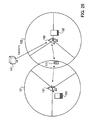
- FIG. 26 showing a mobile communication system
- BSs base stations
- terminal 111 a terminal 111
- cells 121 and 122 representing the coverage of the respective base stations 101 and 102.
- the terminal 111 receives common pilot signals (pilots) from the base stations 101 and 102, and compares the received power levels to determine whether to ask for a handover (HO).
- pilots common pilot signals
- the terminal 111 As the terminal 111 moves from the current cell 121 toward its neighboring cell 122 as indicated by the arrow in FIG. 26, the terminal 111 receives a higher power level from the neighboring base station 102. At this time, the terminal 111 sends a handover request to the current base station 101 to initiate a handover to the base station 102.
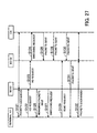
- FIG. 27 illustrates a handover operation in the mobile communication system. This operation is performed by the terminal 111 and the base stations 101 and 102, all appearing in FIG. 26, and a core network (CN).
- CN core network
- Step S121 The terminal 111 in the cell 121 exchanges packets with the core network through the current base station 101. Using the general and common core network protocol, the terminal 111 could communicate with another terminal or the like (normal communication).
- Step S122 Suppose that the terminal 111 moves into the cell 122. Consequently, the pilot power level of the base station 102 becomes higher than that of the base station 101, and thus the terminal 111 sends a handover request to the base station 101.
- Step S123 The base station 101 transfers the received handover request to the base station 102 which is the target of handover.
- Step S124 On receiving the handover request from the terminal 111, the base station 102 sends a switching request to the core network. Consequently, the core network switches the edge node from the base station 101 to the base station 102.
- Step S125 The base station 101 transmits untransmitted packets remaining therein to the terminal 111.
- Step S126 The core network, having received the switching request, starts to route packets destined for the terminal 111 to the base station 102.
- Step S127 On completing the transmission of all the remaining packets to the terminal 111, the base station 101 sends a handover switching request to the terminal 111.
- Step S128 The core network routes packets to the base station 102, if any.
- Step S129 The terminal 111, having received the handover switching request transmits a packet send request to the base station 102.
- Step S130 The core network keeps routing packets to the base station 102, if any. Those packets are accumulated in the base station 102.
- Step S131 The base station 102, having received the send request, starts to transmit accumulated packets to the terminal 111.
- Step S132 The terminal 111 exchanges packets with the core network through the base station 102. Using the general and common core network protocol, the terminal 111 can thereby communicate with another terminal or the like (normal communication).
- the handover source base station 101 has remaining packets to be transmitted, and subsequent packets (packets in steps S126, S128, and S130) are transmitted and accumulated in the handover target base station 102.
- FIG. 28 illustrates remaining packets and accumulated packets.
- like reference numerals are used to denote like elements appearing in FIG. 26, and description of such elements is omitted.
- This figure shows a memory 131 storing packets remaining in the base station 101, a memory 132 storing packets accumulated in the base station 102, and a core network 141.
- the terminal 111 receives the remaining packets from the base station 101, and then the accumulated packets from the base station 102.
- the terminal 111 Since the terminal 111 sends a handover request when a power level from the base station 102 becomes higher than that from the base station 101, the terminal 111 has to receive the remaining packets from the base station 101 under interference from the cell 122 of the base station 102.
- a cellular system has been proposed in which a mobile station can transmit Acknowledge/Non-Acknowledge (ACK/NACK) signals through High-speed Dedicated Physical Control Channel (HS-DPCCH) at a low error rate and without packet loss even when it is connected to a plurality of base stations on Dedicated Physical Channel (DPCH) to achieve a soft handover (cf. Japanese Unexamined Patent Publication No. 2004-7030 ).
- HS-DPCCH High-speed Dedicated Physical Control Channel
- DPCH Dedicated Physical Channel
- the present invention was made in view of the above circumstances, and embodiments thereof may provide a communication device which allows remaining packets to be transmitted under reduced inter-cell interference, to thereby improve throughput of the remaining packets.
- a communication device incorporated in a base station for allocating a plurality of frequency bands each to different terminals, to enable wireless communication.
- the communication device comprises a power booster for increasing transmission power of one of the frequency bands, and a frequency band allocator for allocating the frequency band with the increased transmission power to a terminal which is performing a handover.
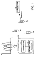
- FIG. 1 schematically illustrates a communication device. This figure shows communication devices 1 and 3 installed in respective base stations, and terminals 2a to 2n communicating on radio channels with the communication device 1, along with a graph showing the relationships between frequency bands allocated to the terminals 2a to 2n by the communication device 1 and transmission power levels.
- the communication device 1 allocates a plurality of frequency bands f1 to f4 among terminals 2a to 2n for wireless communication, typically but not necessarily on a one-to-one basis. For example, frequency band f1 is allocated to the terminal 2a, frequency band f2 to the terminal 2b, and frequency band f3 to the terminal 2n.
- the communication device 1 includes a power booster 1a and a frequency band allocator 1b.
- the power booster 1a equally distributes transmission power among the frequency bands f1 to f4.
- the power booster 1a increases transmission power of one of the frequency bands f1 to f4, including both transmit data and pilot.
- the frequency band allocator 1b allocates the frequency band with the increased transmission power to the requesting terminal.
- the power booster 1a increases the transmission power of frequency band f4, as seen from the graph of FIG. 1.
- the frequency band allocator 1b allocates that frequency band f4 to the terminal 2a.
- the increased transmission power suppresses inter-cell interference and allows the communication device 1 to transmit remaining packets to the terminal 2a with improved throughput.
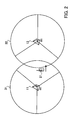
- FIG. 2 shows an exemplary configuration of a mobile communication system. This figure shows base stations 11 and 12, a terminal 21, and cells 31 and 32 representing the coverage of the respective base stations 11 and 12.
- the terminal 21 receives common pilots from the base stations 11 and 12. Then, based on the received common pilots, the terminal 21 calculates and sends wireless qualities such as Channel Quality Indicator (CQI) to the base stations 11 and 12. In accordance with the received wireless quality, each of the base stations 11 and 12 allocates one of a plurality of frequency bands to the terminal 21 for communication.
- CQI Channel Quality Indicator
- the terminal 21 compares the received power levels of the common pilots to determine whether to ask for a handover. As indicated by the arrow in FIG. 2, when the terminal 21 moves from the cell 31 into the cell 32 and finds that the received power from the base station 12 has become higher than that from the base station 11, the terminal 21 sends a handover request to the base station 11 for a handover to the base station 12.
- the handover source base station 11 receiving this request increases transmission power of one frequency band and allocates this frequency band to the requesting terminal 21.
- the handover target base station 12 detects the frequency band used by the terminal 21 as an interference signal and decreases the transmission power of that frequency band.
- the handover source base station 11 assigns the frequency band with increased power to the terminal 21 while the handover target base station 12 decreases power of the frequency band used by the terminal 21, whereby inter-cell interference can be reduced, and this improves transmission/reception throughput of remaining packets.
- the following describes in detail how the base stations 11 and 12 shown in FIG. 2 change transmission power. First, the power increase by the handover source base station 11 will be explained.
- FIG. 3 is a graph showing the power levels of the base station during normal communication, wherein the horizontal axis indicates frequency bands allocated to terminals and the vertical axis indicates transmission power levels of the base station 11.
- the base station 11 allocates one of the frequency bands f1 to f4, for example, to the terminal 21 for communication. While a handover is not executed (during normal communication), the base station 11 equally distributes power among the frequency bands f1 to f4, as shown in FIG. 3.
- FIG. 4 is a graph showing the power levels of the base station that has received a handover request, wherein the horizontal axis indicates frequency bands and the vertical axis indicates transmission power levels.
- the base station 11 On receiving a handover request from the terminal 21, the base station 11 increases power of one of the frequency bands. For example, the base station 11 increases the power of frequency band f4, as shown in FIG. 4. Then, the base station 11 allocates that frequency band f4 to the requesting terminal 21, so as to communicate with the terminal 21 with increased power.
- the base station 11 may increase the power of the frequency band currently used by a requesting terminal. Specifically, if the terminal sends a handover request at frequency band f4, the power of that frequency band f4 may be increased.
- the power of the other frequency bands f1 to f3 should be controlled because the total transmission power of a base station is fixed.
- the power for frequency band f3 is allotted to frequency band f4 so as not to exceed the maximum limit of total transmission power, as shown in FIG. 4.
- a plurality of frequency bands may be reduced in power.
- FIG. 5 illustrates scheduling during normal communication, wherein the horizontal axis indicates frequency bands allocated to terminals and the vertical axis indicates time.
- the base station 11 successively allocates, to the terminals, frequency bands that have good wireless quality at that time. For example, as indicated by the rectangles in FIG. 5, the terminal 21 is successively allocated frequency bands f1, f3, f2 and f4 in that order. The frequency bands that are not allocated to the terminal 21 at each time point are allocated to other different terminals.
- FIG. 6 illustrates scheduling of the base station 11 receiving a handover request, wherein the horizontal axis indicates frequency bands allocated to terminals and the vertical axis indicates time.
- the base station 11 Upon receiving the handover request from the terminal 21, the base station 11 increases the power of a frequency band f4, as shown in FIG. 4, and then allocates the frequency band f4 with the increased power to the requesting terminal 21. That is to say, only the frequency band f4 is allocated to the terminal 21 as indicated by the rectangles in FIG. 6.
- the base station 11 is allowed to transmit remaining packets to the terminal 21, which is roaming across the boundary between cells 31 and 32, using the frequency band with the increased power, resulting in improved transmission/reception throughput of those packets.
- the base station 11 After transmitting all remaining packets to the terminal 21, the base station 11 returns to a normal process where power is equally distributed as shown in FIG. 3 and the terminal 21 is sequentially allocated different frequency bands f1 to f4 as shown in FIG. 5.
- the base station 11 starts to increase the power on receiving a handover request from the terminal 21.
- the base station 11 may initiate the power control when the Quality of Service (QoS) level of remaining packets for the terminal 21 exceeds a predetermined threshold after the reception of the handover request.
- QoS Quality of Service
- FIG. 7 is a graph illustrating such QoS-based power control process, wherein the horizontal axis indicates time and the vertical axis indicates the QoS level of remaining packets.
- the base station 11 is designed to discard remaining packets for the terminal 21 after a lapse of a time t1 so that the packets may not remain in its memory unduly long. To avoid untransmitted packets from being discarded, the QoS level of remaining packets is increased, which is a trigger for a power control process.
- the base station 11 increases the power level for frequency band f4 as shown in FIG. 4, and executes scheduling such that the frequency band f4 will be allocated to the terminal 21 as shown in FIG. 6.
- the base station 11 may be capable of transmitting all of the remaining packets to the terminal 21 before the QoS level exceeds the threshold. If this is the case, the base station 11 does not perform the power control process, and the terminal 21 is not allocated a frequency band with increased power.
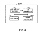
- the base station 11 includes a handover request receiver 11a, a QoS comparator 11b, a power controller 11c, and a scheduler 11d.
- the handover request receiver 11a When a handover request arrives from a terminal 21, the handover request receiver 11a notifies the QoS comparator 11b of the reception of the request.
- the QoS comparator 11b compares the QoS level of remaining packets stored in memory with a threshold. When the QoS level is higher than the threshold, the QoS comparator 11b notifies the power controller 11c and the scheduler 11d that the QoS level of the remaining packets has exceeded the threshold.
- the power controller 11c receiving this notification controls power levels for wireless communication with the terminal 21.
- the power of frequency band f3 is allotted to frequency band f4, as shown in FIG. 4.
- the scheduler 11d receiving the notification from the QoS comparator 11 allocates the frequency band with the increased power to the requesting terminal. For example, frequency band f4 is allocated to the terminal 21, as shown in FIG. 6.
- the scheduler 11d performs normal scheduling according to adaptive modulation. Specifically, the scheduler 11d allocates the remaining frequency bands f1 to f3 to the terminals. If the power of frequency band f3 has been allotted in its entirety to frequency band f4, the scheduler 11d allocates other frequency bands f1 and f2 to the terminals.
- the QoS comparator 11b of FIG. 8 can be omitted if the power control and the scheduling are desired to be initiated on reception of a handover request, irrespective QoS level. Further, the scheduler 11d may be designed to function also as the handover request receiver 11a, the QoS comparator 11b and the power controller 11c.
- the terminal 21 roaming through the boundary between cells 31 and 32 is allocated a frequency band with increased power by the handover source base station 11.
- the terminal 21 can receive remaining packets at the increased power level, resulting in improved transmission/reception throughput of the remaining packets.
- the improved throughput shortens time required for a handover.
- FIG. 9 shows an exemplary configuration of the mobile communication system.
- like reference numerals denote like elements appearing in FIG. 2, and description of such elements is omitted.
- terminals 41 to 44 are located within a cell 32. It is assumed here that the terminals 41, 42, 43 and 44 are currently allocated frequency bands f4, f3, f2 and f1, respectively, and that the base station 11 has increased the power of frequency band f4 in response to a handover request from the terminal 21.
- the terminal 41 at the boundary between cells 31 and 32 is communicating with the base station 12 using frequency band f4.
- the increased power interferes with this communication.
- the base station 11 has doubled the power of the frequency band f4.
- the interference power becomes twofold (+3dB) and thus the CQI of the terminal 41 deteriorates by about 3 dB.
- the power increase does not affect CQIs of the other terminals 42 to 44 using different frequency bands f1 to f3.
- the base station 12 can detect which frequency band the base station 11 has boosted, by monitoring wireless qualities of the terminals 41 to 44. Then the base station 12 decreases the power of the detected frequency band.
- the power decrease for frequency band f3 reduces interference with communication at frequency band f3 in the adjacent cell, and the CQI of the terminal 42 improves.
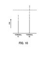
- FIG. 10 shows the CQIs of the terminals 41 and 42 communicating with a handover target base station 12.
- the terminals 41 to 44 each receives a common pilot from the base station 12 and calculates a Signal to Interference and Noise Ratio (SINR). Then, each of the terminals 41 to 44 converts the SINR, which is a continuous value, to a CQI, which is a discrete value, and transmits the CQI to the base station 12. For example, SINRs of 0 to 1 dB are converted to CQI "1", SINRs of 1 to 2 dB to CQI "2", and SINRs of 2 to 3 dB to CQI "3". Wireless quality elements other than SINR and CQI can be used, provided that the base station 12 can confirm the wireless qualities of the terminals 41 to 44.
- SINRs of 0 to 1 dB are converted to CQI "1"
- the CQI of the terminal 41 using frequency band f4 for communication decreases below a level indicated by the dashed line in FIG. 10, due to the interference from the cell of the base station 11.
- the dashed line indicates the CQI of the terminal 41 before the power of the frequency band f4 is increased by the base station 11.
- the CQI of the terminal 42 using frequency band f3 for communication increases above the level indicated by the dashed line in FIG. 10, because of the disappearance of the interference from the cell of the base station 11.
- the dashed line indicates the CQI of the terminal 42 before the power of the frequency band f4 is increased by the base station 11.
- CQIs of the terminals 41 to 44 are responsive to power changes made by the base station 11. Accordingly, the handover target base station 12 monitors CQIs of the terminals 41 to 44 to detect the frequency bands of which the power levels have been changed by the handover source base station 11. The handover target base station 12 decreases the power of a frequency band of a decreased CQI. This may apply to multiple frequency bands simultaneously.
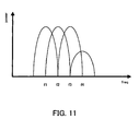
- FIG. 11 is a graph showing power levels of a handover target base station that has received a handover request, wherein the horizontal axis indicates frequency bands and the vertical axis indicates transmission power levels.
- the handover target base station 12 On detecting a frequency band whose power has been increased by the handover source base station 11, the handover target base station 12 decreases the power of the detected frequency band.
- the power of frequency band f4 has been increased by the handover source base station 11.
- the handover target base station 12 decreases the power of frequency band f4, as shown in FIG. 11. This reduces the inter-cell interference of frequency band f4, whereby the handover source base station 11 can transmit remaining packets to the terminal 21 using frequency band f4 with enhanced throughput.
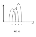
- FIG. 12 is another graph showing power levels of a handover target base station that has received a handover request, wherein the horizontal axis indicates frequency bands and the vertical axis indicates transmission power levels.
- the power of frequency band f4 is merely decreased; in the example shown in FIG. 12, the decreased power is allotted to another frequency band, for example, frequency band f3 whose CQI is intended to increase. This improves throughput of packets exchanged between the base station 12 and the terminal 42.
- the handover source base station 11 increases power for transmitting a common pilot as well as power for a specific frequency band for transmitting packets (communication data).
- the handover target base station 12 decreases only the specific frequency band for transmitting packets, while holding the common pilot transmission power.
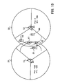
- FIG. 13 illustrates power levels of a handover source base station, and power levels of a handover target base station.
- like reference numerals denote like elements appearing in FIG. 9, and description of such elements is omitted.
- "Pilot” and "Info” written in the cells 31 and 32 indicate how much common pilot transmission power and packet transmission power are changed.
- the handover source base station 11 increases the common pilot transmission power by +3 dB and also increases the power of the frequency band f4 for transmitting packets by +3 dB.
- the handover target base station 12 keeps the common pilot transmission power (0 dB) unchanged and decreases, by 3 dB, the power of frequency band f4 for transmitting packets.
- the terminal 21 Since the base station 11 increases the common pilot transmission power by +3 dB, the terminal 21 returns, to the base station 11, its CQI enhanced by +3 dB. This enables the base station 11 to increase the amount of data that can be exchanged at a time with the terminal 21. Also, since the packet transmission power is increased by +3 dB, it is possible to reduce packet errors caused due to inter-cell interference.
- the handover target base station 12 decreases the packet transmission power by 3 dB, and therefore, the inter-cell interference of frequency band f4 can be further reduced, making it possible to further reduce packet errors. Also, packet errors due to CQI delay can be reduced.
- FIG. 14 illustrates CQI delay, wherein the horizontal axis indicates time.
- the base station 11 outputs a common pilot as shown in this figure, and the terminal 21 receives the common pilot from the base station 11, calculates and transmits a CQI to the base station 11 at the illustrated timing. In accordance with the received CQI, the base station 11 transmits remaining packets.
- the transmitted CQI does not exactly indicate the signal quality at the time of transmitting remaining packets.
- the terminal 21 may therefore experience packet errors.
- the packet errors can be reduced irrespective of CQI delays.
- the handover target base station 12 does not increase the common pilot transmission power, in order that the common pilot of the base station 12 may not adversely affect the measurement of CQI of the base station 11 by the terminal 21.
- the base station 12 includes a CQI receiver 12a, a frequency band detector 12b, and a power controller 12c.
- the CQI receiver 12a receives CQIs from terminals 41 to 44 located in a cell 32.
- the frequency band detector 12b detects the frequency bands of which the power levels have been changed by the handover source base station 11.
- the power controller 12c controls power levels for the detected frequency bands. For example, the power controller 12c decreases the power of frequency band f4, which has been increased by the handover source base station 11, and increases the power of frequency band f3, which has been decreased by the base station 11, as shown in FIGS. 11 and 12.
- the power controller 12c keeps the common pilot transmission power unchanged and increases/decreases only the packet transmission power.
- the base station 12 initiates this process when receiving a handover request from the base station 11, and terminates it when receiving a packet send request from the terminal 21.
- a scheduler for adaptive modulation performs scheduling in accordance with CQIs from the terminals 41 to 44, to allocate frequency bands f1 to f4 to the terminals 41 to 44.
- the scheduler may be designed to function also as the CQI receiver 12a, the frequency band detector 12b and the power controller 12c.
- the schedulers of the base stations 11 and 12 each determine a Modulation and Coding Scheme (MCS) for the adaptive modulation in accordance with CQIs received from individual terminals.
- QPSK Quadrature Phase Shift Keying
- R 1/3 coding and with CQIs "0" to "3”.
- MCS "2" is associated with Q
- Decrease of packet transmission power in the handover target base station 12 can reduce packet errors, which results in a reduced need for packet retransmission and enables high-speed transmission of packets.
- FIG. 16 illustrates an operation sequence of the mobile communication system including the handover source base station 11, the handover target base station 12, and the terminal 21 shown in FIGS. 2, 9 and 13.
- Step S1 The terminal 21 being in the cell 31 of the base station 11 exchanges packets with the base station 11 in a usual way without power control.
- Step S2 The terminal 21 moves toward a neighboring cell 32, so that the received power level from the base station 12 becomes higher than that from the base station 11, then the terminal 21 sends a handover request to the base station 11.
- Step S3 The base station 11 transfers the received handover request to the base station 12.
- Step S4 On receiving the handover request from the terminal 21, the base station 11 starts a power control process. For example, the base station 11 increases the power of frequency band f4 by allotting the power of frequency band f3 to the frequency band f4, as shown in FIG. 4. Then, the base station 11 allocates frequency band f4 with the increased power to the requesting terminal 21.
- the base station 11 may initiate a power control process when QoS of remaining packets for the terminal 21 exceeds a predetermined threshold after the reception of a handover request from the terminal 21, as mentioned earlier.
- Step S5 On receiving the handover request from the terminal 21, the base station 12 starts a power control process. For example, the base station 12 receives CQIs from the terminals 41 to 44 located in the cell 32 and based on the received CQIs, and detects the frequency band whose power has been increased by the handover source base station 11. Then, the base station 12 decreases the power of the detected frequency band.
- Step S6 The base station 11 transmits, to the terminal 21, the remaining packets.
- Step S7 When all of the remaining packets are transmitted to the terminal 21, the base station 11 terminates its power control process. Specifically, the base station 11 equally distributes power among the frequency bands, as shown in FIG. 3.
- Step S8 The base station 11 sends a handover switching request to the terminal 21.
- Step S9 The terminal 21 sends a packet send request to the handover target base station 12.
- Step S10 The base station 12 terminates its power control process. Specifically, the base station 12 equally distributes power among the frequency bands.
- Step S11 The base station 12 starts to communicate with the requesting terminal 21. Specifically, the base station 12 transmits, to the terminal 21, accumulated packets, which have been already received from the core network (not shown).
- Step S12 The terminal 21 and the base station 12 exchange packets in a usual way.
- the handover request is made from a terminal in the above example, but such a request may be made from a base station.
- the base station 11 outputs a handover request to a handover target base station 12 depending on wireless quality information received from the terminal 21. In this case, the base station 11 initiates a power control process.
- the terminal 21 and the base station 12 may establish a wireless connection at any time after the handover request is made in Step S2, but preferably before a handover switching request is made in Step S8.
- Step S21 On receiving a handover request from the terminal 21, the base station 11 starts a power control process.
- Step S22 The base station 11 fixes a traffic channel of the requesting terminal 21.
- the traffic channel is an orthogonal channel that the scheduler allocates to terminals by partitioning resources such as frequency band, space and code.
- the foregoing description has assumed frequency bands as a typical example of traffic channels.
- a high-performance terminal can monitor all traffic channels, i.e., frequency bands f1 to f4 shown in FIG. 3.
- the traffic channel (frequency band) f4 carries the handover request from the terminal 21.
- the base station 11 fixes the traffic channel f4 for use by the terminal 21.
- the other traffic channels f1 to f3 are referred to as unfixed traffic channels.
- Step S23 The base station 11 lowers by ⁇ the power of an unfixed traffic channel, for example, f3.
- Step S24 The base station 11 increases by b the power of the traffic channel, i.e., f4 of the terminal 21.
- Step S25 The base station 11 transmits all remaining packets to the terminal 21.
- Step S26 On completing the transmission of the remaining packets, the base station 11 terminates its power control process.
- Step S27 The base station 11 outputs a handover switching request to the terminal 21.
- the base station 11 monitors throughput of remaining packets to be transmitted to the terminal 21 and controls power in order to obtain sufficient throughput.
- Step S31 On receiving a handover request from the terminal 21, the base station 11 starts a power control process.
- Step S32 The base station 11 fixes the traffic channel, for example, f4, of the requesting terminal 21.
- Step S33 The base station 11 initializes a variable i to "0".
- Step S34 The base station 11 lowers by ⁇ i the power of an unfixed traffic channel, for example, f3.
- the value ⁇ i increases with i; namely, the relationship ⁇ i+1 > ⁇ i holds.
- Step S35 The base station 11 increases by ⁇ i the power of the traffic channel, f4 of the terminal 21.
- the value ⁇ i increases with i; namely, the relationship ⁇ i+1 > ⁇ i holds.
- Step S36 The base station 11 observes the throughput of remaining packets. Then, the base station 11 compares the detected throughput with a threshold, and if the detected throughput is acceptable, the flow proceeds to Step S38. Otherwise, the flow proceeds to Step S37.
- Step S37 The base station 11 increments the variable i by "1".
- Step S38 The base station 11 transmits all the remaining packets to the terminal 21.
- Step S39 On completing the transmission of the remaining packets, the base station 11 terminates its power control process.
- Step S40 The base station 11 outputs a handover switching request to the terminal 21.
- Step S51 On receiving a handover request from the handover source base station 11, the base station 12 initiates a power control process.
- Step S52 The base station 12 monitors CQIs of individual traffic channels f1 to f4, which are received from the terminals 41 to 44 located in the cell 32.
- Step S53 The base station 12 determines whether or not a difference in CQI between traffic channels is small enough to be acceptable. If the CQI difference is acceptable, the flow proceeds to Step S58; if not, the flow proceeds to Step S54. In this connection, when the handover source base station 11 is executing its own power control process, the CQI difference becomes big, which leads the base station 12 to Step S54.
- Step S54 The base station 12 determines that the handover source base station 11 has started a power control process.
- Step S55 The base station 12 identifies a traffic channel experiencing the worst CQI. If the handover source base station 11 has increased the power of the traffic channel f4, the base station 12 determines the traffic channel f4.
- Step S56 The base station 12 confirms that the handover source base station 11 has increased the power of the traffic channel detected in the preceding step.
- Step S57 The base station 12 lowers data (packet) transmission power of the detected traffic channel.
- Step S58 The base station 12 determines whether or not a packet send request has arrived from the terminal 21.
- the terminal 21 makes a packet send request after receiving all remaining packets from the handover source base station 11. If the send request has arrived, the flow proceeds to Step S60; if not, the flow proceeds to Step S59.
- Step S59 The base station 12 updates the current values of CQIs with new CQIs received from the terminals 41 to 44.
- Step S60 The base station 12 terminates its power control process.
- the target base station 12 finds a traffic channel with the worst CQI and decreases the power of that traffic channel.
- a traffic channel with the best CQI is also detected and the power of that channel is increased.
- Step S71 On receiving a handover request from the handover source base station 11, the base station 12 initiates a power control process.
- Step S72 The base station 12 monitors CQIs of individual traffic channels f1 to f4, which are received from the terminals 41 to 44 located in the cell 32.
- Step S73 The base station 12 determines whether or not a difference in CQI between traffic channels is small enough to be acceptable. If the CQI difference is acceptable, the flow proceeds to Step S78; if not, the flow proceeds to Step S74. In this connection, when the handover source base station 11 is executing its own control process, the CQI difference becomes big, which leads the base station 12 to Step S74.
- Step S74 The base station 12 determines that the handover source base station 11 has started a power control process.
- Step S75 The base station 12 identifies a worst-CQI traffic channel and a best-CQI traffic channel. If the handover source base station 11 allots the power of traffic channel f3 to traffic channel f4, the base station 12 will identify traffic channel f4 as a worst-CQI channel and traffic channel f3 as a best CQI channel for base station 12.
- Step S76 The base station 12 determines that the handover source base station 11 has changed the power levels for the traffic channels detected in the preceding step. For example, the base station 12 determines that the base station 11 has increased the power of traffic channel f4 and has decreased the power of traffic channel f3.
- Step S77 The base station 12 lowers data transmission power of the detected worst-CQI traffic channel by ⁇ . Also, the base station 12 increases data transmission power of the detected best-CQI traffic channel by ⁇ .
- Step S78 The base station 12 determines whether or not a packet send request has arrived from the terminal 21.
- the terminal 21 sends a packet send request after receiving all remaining packets from the handover source base station 11. If the send request has arrived, the flow proceeds to Step S80; if not, the flow proceeds to Step S79.
- Step S79 The base station 12 updates the current values of CQIs with new CQIs received from the terminals 41 to 44.
- Step S80 The base station 12 terminates its power control process.
- ⁇ and ⁇ bear the relationship ⁇ - ⁇ 0 ( ⁇ >0, ⁇ >0) in order that the output power amplifier will not be saturated.
- the terminal 21 roaming around the boundary between cells 31 and 32 is allocated a traffic channel with increased power by the handover source base station 11 and the same traffic channel with decreased power by the handover target base station 11. This control reduces inter-cell interference and thus improves transmission/reception throughput of remaining packets.
- the throughput drops due to inter-cell interference, requiring a long time to complete a handover.
- a handover to a base station providing a higher power level would be forcibly performed before every remaining packet is transmitted.
- the consequent packet loss results in retransmission of the remaining packets.
- the retransmission is performed via the network without fail, for example, at the upper TCP layer, the packets are significantly delayed.
- the base stations 11 and 12 each perform power control to reduce the inter-cell interference, whereby the throughput of remaining packets improves. Consequently, the time needed for a handover can be shortened, and also all the remaining packets can be transmitted to the terminal 21 before its connection is handed over to the base station 12 providing a higher power level.
- FIG. 21 shows changes of CQIs with time.
- the CQIs received from terminals A1, A2, ..., An are plotted with respect to a certain traffic channel.
- fi the i-th frequency band
- K(fi) the number of terminals using frequency band fi
- CQI(n, fi) the CQI (logarithmic dimension) of a terminal n using frequency band fi.
- the mean value X(t, fi) indicates the average CQI of all terminals in the logarithmic scale.
- X indicates the mean value X obtained as the average CQI of the terminals shown in this figure.
- the handover source base station 11 equally distributes power, as shown in FIG. 3, and that the terminals to which frequency bands are allocated are random yet uniformly exist within the cell 32 of the handover target base station 12.
- the mean values X obtained according to equation (1) will converge to an identical value, irrespective of traffic channels.
- a base station accommodates a large number of terminals.
- the handover source base station 11 equally distributes transmission power among all traffic channels, the following relationship (2) holds true for every j (where i#j and ⁇ denotes approximately equal): X t ⁇ fi ⁇ X t ⁇ fj
- FIG. 22 shows temporal changes of CQIs with respect to traffic channel f3.
- the handover source base station 11 decreases the power of traffic channel f3.
- the terminals A1, A2, ..., An located inside the cell 32 of the base station 12 enjoy improved SINR because the radio interference of the traffic channel f3 lessens.
- the resulting high CQIs raise the mean value X at time t1 as illustrated.
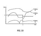
- FIG. 23 shows temporal changes of CQIs with respect to traffic channel f4.
- the handover source base station 11 increases the power of traffic channel f4.
- the terminals located in the cell 32 of the base station 12 experience deteriorated SINR because the radio interference of the traffic channel f4 increases.
- the resulting low CQIs reduce the mean value X at time t1 as illustrated.
- a terminal located closer to the cell 31 receives a smaller power level from the base station 12 and thus a small CQI is calculated.
- the terminal An having a smaller CQI than the terminal A1 can be identified as being located closer to the cell 31 than the terminal A1 is.
- the terminal An located closer to the cell 31 is more liable to be influenced by the power change of the base station 11 and its CQI varies more greatly. For this reason, in the examples of FIGS. 22 and 23, the terminal An shows a greater change in CQI at time t1 than the terminal A1 does.
- the mean value X derived from equation (1) is a statistical mean value of CQIs of the terminals A1, A2, ..., An with respect to a certain traffic channel.
- the mean value X it is possible to monitor CQI changes of the individual traffic channels.
- Another method to detect best and worst channels is to compare the current mean value with an initial mean value X calculated while transmission power is equally distributed. This is referred to as the method 2.
- Step S91 On receiving a handover request from the source base station 11, the target base station 12 starts to monitor CQIs.
- Step S92 The base station 12 calculates the mean values X of individual traffic channels according to equation (1).
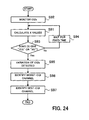
- Step S93 The calculated mean values X are plugged into the expression (3). If expression (3) gives the answer "YES”, the flow proceeds to Step S95; if expression (3) gives the answer "NO”, the flow proceeds to Step S94.
- Step S94 The base station 12 returns back to Step S92 some time later, in order to calculate mean values X of new CQIs with respect to individual traffic channels.
- Step S95 The base station 12 determines that the CQIs of traffic channels are significantly different. Namely, the base station 12 determines that the handover source base station 11 has initiated a power control process.
- Step S96 The base station 12 identifies a traffic channel with the worst CQI according to equation (4).
- Step S97 The base station 12 identifies a traffic channel with the best CQI according to equation (5).
- the base station 12 identifies which traffic channels the neighboring base station 11 has boosted or cut.
- FIG. 25 is a flowchart for the method 2.
- Step S101 On receiving a handover request from the handover source base station 11, the handover target base station 12 starts to monitor CQIs.
- Step S102 The base station 12 calculates a initial mean values X0 of individual traffic channels that are not subjected to the power control by the base station 11.
- Step S103 The base station 12 stores the calculated initial mean values X0 in a memory.
- Step S104 The base station 12 calculates the mean values X of individual traffic channels according to equation (1).
- Step S105 The base station 12 plugs the stored initial mean values X0 and the calculated mean values X into equation (7) to calculate difference P(fi) for individual traffic channels.
- Step S106 The base station 12 plugs the calculated difference P(fi) into expression (8). If expression (8) gives the answer "YES”, the flow proceeds to Step S108; if expression (8) gives the answer "NO”, the flow proceeds to Step S107.
- Step S107 The base station 12 returns back to Step S104 some time later, in order to calculate mean values X of new CQIs with respect to individual traffic channels.
- Step S108 The base station 12 determines that CQIs are significantly different from channel to channel. Namely, the source base station 11 has started a power control process.
- Step S109 The base station 12 identifies a traffic channel with the worst CQI according to equation (9).
- Step S110 The base station 12 identifies a traffic channel with the best CQI according to equation (10).
- the base station 12 identifies which traffic channels the neighboring base station 11 has boosted or cut.
- the handover source base station 11 and the handover target base station 12 are explained separately as having different functions. In practice, however, these base stations can operate as both a handover target base station and a handover source base station. That is to say, when a handover is requested from a terminal in the cell of the base station 12, the base station 12 performs the power control identical with that explained above in relation to the base station 11, and the base station 11 performs the power control identical with that explained above in relation to the base station 12.
- a frequency band with increased transmission power is allocated to a terminal whose connection is to be handed over to another base station. This feature permits the communication device to transmit remaining packets to the terminal with increased transmission power just prior to handover, whereby inter-cell interference on the transmission of the remaining packets can be reduced, making it possible to improve the throughput.
Landscapes
- Engineering & Computer Science (AREA)
- Computer Networks & Wireless Communication (AREA)
- Signal Processing (AREA)
- Mobile Radio Communication Systems (AREA)
Abstract
Description
- The present invention relates to communication devices, and more particularly, to a communication device incorporated in a base station for allocating a plurality of frequency bands among terminals (user equipment) to enable wireless communication.
- In cellular mobile communications system, mobile terminals communicate with a base station on radio channels. As a terminal moves during communication, switchover from one base station to another may take place to keep the wireless communication alive. This switchover operation is called a "handover" in cellular terminology.
- Referring to FIG. 26 showing a mobile communication system, an example of handover will be explained. This figure shows base stations (BSs) 101 and 102, a terminal 111, and
cells respective base stations - The terminal 111 receives common pilot signals (pilots) from the
base stations - As the terminal 111 moves from the
current cell 121 toward itsneighboring cell 122 as indicated by the arrow in FIG. 26, the terminal 111 receives a higher power level from the neighboringbase station 102. At this time, the terminal 111 sends a handover request to thecurrent base station 101 to initiate a handover to thebase station 102. - FIG. 27 illustrates a handover operation in the mobile communication system. This operation is performed by the terminal 111 and the
base stations - Step S121: The terminal 111 in the
cell 121 exchanges packets with the core network through thecurrent base station 101. Using the general and common core network protocol, the terminal 111 could communicate with another terminal or the like (normal communication). - Step S122: Suppose that the terminal 111 moves into the
cell 122. Consequently, the pilot power level of thebase station 102 becomes higher than that of thebase station 101, and thus the terminal 111 sends a handover request to thebase station 101. - Step S123: The
base station 101 transfers the received handover request to thebase station 102 which is the target of handover. - Step S124: On receiving the handover request from the terminal 111, the
base station 102 sends a switching request to the core network. Consequently, the core network switches the edge node from thebase station 101 to thebase station 102. - Step S125: The
base station 101 transmits untransmitted packets remaining therein to the terminal 111. - Step S126: The core network, having received the switching request, starts to route packets destined for the terminal 111 to the
base station 102. - Step S127: On completing the transmission of all the remaining packets to the terminal 111, the
base station 101 sends a handover switching request to the terminal 111. - Step S128: The core network routes packets to the
base station 102, if any. - Step S129: The terminal 111, having received the handover switching request transmits a packet send request to the
base station 102. - Step S130: The core network keeps routing packets to the
base station 102, if any. Those packets are accumulated in thebase station 102. - Step S131: The
base station 102, having received the send request, starts to transmit accumulated packets to the terminal 111. - Step S132: The terminal 111 exchanges packets with the core network through the
base station 102. Using the general and common core network protocol, the terminal 111 can thereby communicate with another terminal or the like (normal communication). - As described above, when the terminal 111 sends the handover request, the handover
source base station 101 has remaining packets to be transmitted, and subsequent packets (packets in steps S126, S128, and S130) are transmitted and accumulated in the handovertarget base station 102. - FIG. 28 illustrates remaining packets and accumulated packets. In FIG. 28, like reference numerals are used to denote like elements appearing in FIG. 26, and description of such elements is omitted.
- This figure shows a
memory 131 storing packets remaining in thebase station 101, amemory 132 storing packets accumulated in thebase station 102, and acore network 141. At the time of a handover, theterminal 111 receives the remaining packets from thebase station 101, and then the accumulated packets from thebase station 102. - Since the
terminal 111 sends a handover request when a power level from thebase station 102 becomes higher than that from thebase station 101, theterminal 111 has to receive the remaining packets from thebase station 101 under interference from thecell 122 of thebase station 102. - As stated above, a handover takes place around the boundary between cells, and therefore, the adjacent cell interferes with reception of remaining packets, which results in a lower throughput of the packets.
- Meanwhile, a cellular system has been proposed in which a mobile station can transmit Acknowledge/Non-Acknowledge (ACK/NACK) signals through High-speed Dedicated Physical Control Channel (HS-DPCCH) at a low error rate and without packet loss even when it is connected to a plurality of base stations on Dedicated Physical Channel (DPCH) to achieve a soft handover (cf.
Japanese Unexamined Patent Publication No. 2004-7030 - The present invention was made in view of the above circumstances, and embodiments thereof may provide a communication device which allows remaining packets to be transmitted under reduced inter-cell interference, to thereby improve throughput of the remaining packets.
- According to the invention, there is provided a communication device incorporated in a base station for allocating a plurality of frequency bands each to different terminals, to enable wireless communication. The communication device comprises a power booster for increasing transmission power of one of the frequency bands, and a frequency band allocator for allocating the frequency band with the increased transmission power to a terminal which is performing a handover.
- The above and other features and advantages of the present invention will become apparent from the following description when taken in conjunction with the accompanying drawings which illustrate preferred embodiments of the present invention by way of example, and in which:
- FIG. 1 schematically illustrates a communication device.
- FIG. 2 shows an exemplary configuration of a mobile communication system.
- FIG. 3 shows power levels of a base station during normal communication.
- FIG. 4 shows power levels of the base station receiving a handover request.
- FIG. 5 illustrates scheduling during normal communication .
- FIG. 6 illustrates scheduling for a handover.
- FIG. 7 illustrates a power control process according to QoS.
- FIG. 8 is a functional block diagram of a base station.
- FIG. 9 shows an exemplary configuration of a mobile communication system.
- FIG. 10 shows CQIs of terminals communicating with a handover target base station.
- FIGS. 11 and 12 show power levels of a handover target the base station.
- FIG. 13 illustrates power levels of the handover source base station and output power levels of the handover target base station.
- FIG. 14 illustrates CQI delay.
- FIG. 15 is a functional block diagram of the base station.
- FIG. 16 shows an operation sequence of the mobile communication system.
- FIG. 17 is a flowchart showing a process executed by the handover source base station.
- FIG. 18 is a flowchart showing another process executed by the handover source base station.
- FIG. 19 is a flowchart showing a process executed by the handover target base station.
- FIG. 20 is a flowchart showing another process executed by the handover target base station.
- FIG. 21 shows changes of CQIs with time.
- FIG. 22 shows temporal changes of CQIs with respect to a traffic channel f3.
- FIG. 23 shows temporal changes of CQIs with respect to a traffic channel f4.
- FIG. 24 is a flowchart of
method 1. - FIG. 25 is a flowchart of method 2.
- FIG. 26 illustrates a handover performed in a mobile communication system.
- FIG. 27 illustrates an operation sequence of the mobile communication system of FIG. 26.
- FIG. 28 illustrates remaining packets and accumulated packets.
- The principles of the present invention will be described below with reference to the accompanying drawings.
- FIG. 1 schematically illustrates a communication device. This figure shows
communication devices terminals 2a to 2n communicating on radio channels with thecommunication device 1, along with a graph showing the relationships between frequency bands allocated to theterminals 2a to 2n by thecommunication device 1 and transmission power levels. - The
communication device 1 allocates a plurality of frequency bands f1 to f4 amongterminals 2a to 2n for wireless communication, typically but not necessarily on a one-to-one basis. For example, frequency band f1 is allocated to the terminal 2a, frequency band f2 to the terminal 2b, and frequency band f3 to the terminal 2n. Thecommunication device 1 includes apower booster 1a and afrequency band allocator 1b. - In usual circumstances the
power booster 1a equally distributes transmission power among the frequency bands f1 to f4. When a handover is requested, thepower booster 1a increases transmission power of one of the frequency bands f1 to f4, including both transmit data and pilot. Then thefrequency band allocator 1b allocates the frequency band with the increased transmission power to the requesting terminal. - Suppose that the terminal 2a is experiencing a handover from the
communication device 1 to thecommunication device 3. Thepower booster 1a increases the transmission power of frequency band f4, as seen from the graph of FIG. 1. Then thefrequency band allocator 1b allocates that frequency band f4 to the terminal 2a. The increased transmission power suppresses inter-cell interference and allows thecommunication device 1 to transmit remaining packets to the terminal 2a with improved throughput. - Preferred embodiments of the present invention will now be described in detail with reference to the drawings, wherein like reference numerals refer to like elements throughout.
- FIG. 2 shows an exemplary configuration of a mobile communication system. This figure shows
base stations cells respective base stations - The terminal 21 receives common pilots from the
base stations base stations base stations - The terminal 21 compares the received power levels of the common pilots to determine whether to ask for a handover. As indicated by the arrow in FIG. 2, when the terminal 21 moves from the
cell 31 into thecell 32 and finds that the received power from thebase station 12 has become higher than that from thebase station 11, the terminal 21 sends a handover request to thebase station 11 for a handover to thebase station 12. - The handover
source base station 11 receiving this request increases transmission power of one frequency band and allocates this frequency band to the requestingterminal 21. The handovertarget base station 12 detects the frequency band used by the terminal 21 as an interference signal and decreases the transmission power of that frequency band. - As described above, the handover
source base station 11 assigns the frequency band with increased power to the terminal 21 while the handovertarget base station 12 decreases power of the frequency band used by the terminal 21, whereby inter-cell interference can be reduced, and this improves transmission/reception throughput of remaining packets. - The following describes in detail how the
base stations source base station 11 will be explained. - FIG. 3 is a graph showing the power levels of the base station during normal communication, wherein the horizontal axis indicates frequency bands allocated to terminals and the vertical axis indicates transmission power levels of the
base station 11. - The
base station 11 allocates one of the frequency bands f1 to f4, for example, to the terminal 21 for communication. While a handover is not executed (during normal communication), thebase station 11 equally distributes power among the frequency bands f1 to f4, as shown in FIG. 3. - FIG. 4 is a graph showing the power levels of the base station that has received a handover request, wherein the horizontal axis indicates frequency bands and the vertical axis indicates transmission power levels.
- On receiving a handover request from the terminal 21, the
base station 11 increases power of one of the frequency bands. For example, thebase station 11 increases the power of frequency band f4, as shown in FIG. 4. Then, thebase station 11 allocates that frequency band f4 to the requestingterminal 21, so as to communicate with the terminal 21 with increased power. - It should be noted that the
base station 11 may increase the power of the frequency band currently used by a requesting terminal. Specifically, if the terminal sends a handover request at frequency band f4, the power of that frequency band f4 may be increased. - To increase the power of frequency band f4, the power of the other frequency bands f1 to f3 should be controlled because the total transmission power of a base station is fixed. For example, the power for frequency band f3 is allotted to frequency band f4 so as not to exceed the maximum limit of total transmission power, as shown in FIG. 4. A plurality of frequency bands may be reduced in power.
- In the case where frequency band f3 devotes its entire port (power) to frequency band f4, the power of frequency band f4 increases by +3 dB. Consequently, assuming that the inter-cell interference remains unchanged, the wireless quality (CQI) of the terminal 21 improves by +3 dB. That is to say, the CQI correlated with the maximum transmission rate can be improved by +3 dB, thus making it possible to improve the throughput.
- Scheduling of the
base station 11 will now be explained. - FIG. 5 illustrates scheduling during normal communication, wherein the horizontal axis indicates frequency bands allocated to terminals and the vertical axis indicates time.
- The
base station 11 successively allocates, to the terminals, frequency bands that have good wireless quality at that time. For example, as indicated by the rectangles in FIG. 5, the terminal 21 is successively allocated frequency bands f1, f3, f2 and f4 in that order. The frequency bands that are not allocated to the terminal 21 at each time point are allocated to other different terminals. - FIG. 6 illustrates scheduling of the
base station 11 receiving a handover request, wherein the horizontal axis indicates frequency bands allocated to terminals and the vertical axis indicates time. - Upon receiving the handover request from the terminal 21, the
base station 11 increases the power of a frequency band f4, as shown in FIG. 4, and then allocates the frequency band f4 with the increased power to the requestingterminal 21. That is to say, only the frequency band f4 is allocated to the terminal 21 as indicated by the rectangles in FIG. 6. - Consequently, the
base station 11 is allowed to transmit remaining packets to the terminal 21, which is roaming across the boundary betweencells - After transmitting all remaining packets to the terminal 21, the
base station 11 returns to a normal process where power is equally distributed as shown in FIG. 3 and the terminal 21 is sequentially allocated different frequency bands f1 to f4 as shown in FIG. 5. - In the above example, the
base station 11 starts to increase the power on receiving a handover request from the terminal 21. Alternatively, thebase station 11 may initiate the power control when the Quality of Service (QoS) level of remaining packets for the terminal 21 exceeds a predetermined threshold after the reception of the handover request. - FIG. 7 is a graph illustrating such QoS-based power control process, wherein the horizontal axis indicates time and the vertical axis indicates the QoS level of remaining packets.
- The
base station 11 is designed to discard remaining packets for the terminal 21 after a lapse of a time t1 so that the packets may not remain in its memory unduly long. To avoid untransmitted packets from being discarded, the QoS level of remaining packets is increased, which is a trigger for a power control process. - For example, when the QoS level exceeds a threshold TH as shown in FIG. 7, the
base station 11 increases the power level for frequency band f4 as shown in FIG. 4, and executes scheduling such that the frequency band f4 will be allocated to the terminal 21 as shown in FIG. 6. - The
base station 11 may be capable of transmitting all of the remaining packets to the terminal 21 before the QoS level exceeds the threshold. If this is the case, thebase station 11 does not perform the power control process, and the terminal 21 is not allocated a frequency band with increased power. - The functions of the
base station 11 will now be described with reference to FIG. 8. As illustrated, thebase station 11 includes ahandover request receiver 11a, aQoS comparator 11b, apower controller 11c, and ascheduler 11d. - When a handover request arrives from a terminal 21, the
handover request receiver 11a notifies theQoS comparator 11b of the reception of the request. TheQoS comparator 11b compares the QoS level of remaining packets stored in memory with a threshold. When the QoS level is higher than the threshold, theQoS comparator 11b notifies thepower controller 11c and thescheduler 11d that the QoS level of the remaining packets has exceeded the threshold. - The
power controller 11c receiving this notification controls power levels for wireless communication with the terminal 21. For example, the power of frequency band f3 is allotted to frequency band f4, as shown in FIG. 4. - The
scheduler 11d receiving the notification from theQoS comparator 11 allocates the frequency band with the increased power to the requesting terminal. For example, frequency band f4 is allocated to the terminal 21, as shown in FIG. 6. - With respect to terminals not requesting handover, the
scheduler 11d performs normal scheduling according to adaptive modulation. Specifically, thescheduler 11d allocates the remaining frequency bands f1 to f3 to the terminals. If the power of frequency band f3 has been allotted in its entirety to frequency band f4, thescheduler 11d allocates other frequency bands f1 and f2 to the terminals. - The
QoS comparator 11b of FIG. 8 can be omitted if the power control and the scheduling are desired to be initiated on reception of a handover request, irrespective QoS level. Further, thescheduler 11d may be designed to function also as thehandover request receiver 11a, theQoS comparator 11b and thepower controller 11c. - As described above, the terminal 21 roaming through the boundary between
cells source base station 11. The terminal 21 can receive remaining packets at the increased power level, resulting in improved transmission/reception throughput of the remaining packets. The improved throughput shortens time required for a handover. - The following describes how the
base station 12 decreases a power level. By decreasing power of a frequency band used by a requesting terminal, thebase station 12 reduces interference with transmission/reception of remaining packets, resulting in improved throughput of the remaining packets transmitted from thebase station 11 to the terminal 21. - FIG. 9 shows an exemplary configuration of the mobile communication system. In the figure, like reference numerals denote like elements appearing in FIG. 2, and description of such elements is omitted.
- As illustrated,
terminals 41 to 44 are located within acell 32. It is assumed here that theterminals base station 11 has increased the power of frequency band f4 in response to a handover request from the terminal 21. - The terminal 41 at the boundary between
cells base station 12 using frequency band f4. The increased power interferes with this communication. Suppose that thebase station 11 has doubled the power of the frequency band f4. The interference power becomes twofold (+3dB) and thus the CQI of the terminal 41 deteriorates by about 3 dB. The power increase does not affect CQIs of theother terminals 42 to 44 using different frequency bands f1 to f3. - Accordingly, the
base station 12 can detect which frequency band thebase station 11 has boosted, by monitoring wireless qualities of theterminals 41 to 44. Then thebase station 12 decreases the power of the detected frequency band. - In the case where the
base station 11 has increased the power of frequency band f4 by allotting the power of frequency band f3 to frequency band f4, as explained above with reference to FIG. 4, the power decrease for frequency band f3 reduces interference with communication at frequency band f3 in the adjacent cell, and the CQI of the terminal 42 improves. - FIG. 10 shows the CQIs of the
terminals target base station 12. Theterminals 41 to 44 each receives a common pilot from thebase station 12 and calculates a Signal to Interference and Noise Ratio (SINR). Then, each of theterminals 41 to 44 converts the SINR, which is a continuous value, to a CQI, which is a discrete value, and transmits the CQI to thebase station 12. For example, SINRs of 0 to 1 dB are converted to CQI "1", SINRs of 1 to 2 dB to CQI "2", and SINRs of 2 to 3 dB to CQI "3". Wireless quality elements other than SINR and CQI can be used, provided that thebase station 12 can confirm the wireless qualities of theterminals 41 to 44. - In the case where the power of the frequency band f4 is increased in the
base station 11 by allotting the power of frequency band f3 to frequency band f4, the CQI of the terminal 41 using frequency band f4 for communication decreases below a level indicated by the dashed line in FIG. 10, due to the interference from the cell of thebase station 11. In the figure, the dashed line indicates the CQI of the terminal 41 before the power of the frequency band f4 is increased by thebase station 11. - On the other hand, the CQI of the terminal 42 using frequency band f3 for communication increases above the level indicated by the dashed line in FIG. 10, because of the disappearance of the interference from the cell of the
base station 11. In the figure, the dashed line indicates the CQI of the terminal 42 before the power of the frequency band f4 is increased by thebase station 11. - CQIs of the
terminals 41 to 44 are responsive to power changes made by thebase station 11. Accordingly, the handovertarget base station 12 monitors CQIs of theterminals 41 to 44 to detect the frequency bands of which the power levels have been changed by the handoversource base station 11. The handovertarget base station 12 decreases the power of a frequency band of a decreased CQI. This may apply to multiple frequency bands simultaneously. - FIG. 11 is a graph showing power levels of a handover target base station that has received a handover request, wherein the horizontal axis indicates frequency bands and the vertical axis indicates transmission power levels.
- On detecting a frequency band whose power has been increased by the handover
source base station 11, the handovertarget base station 12 decreases the power of the detected frequency band. Suppose that the power of frequency band f4 has been increased by the handoversource base station 11. In this case, the handovertarget base station 12 decreases the power of frequency band f4, as shown in FIG. 11. This reduces the inter-cell interference of frequency band f4, whereby the handoversource base station 11 can transmit remaining packets to the terminal 21 using frequency band f4 with enhanced throughput. - FIG. 12 is another graph showing power levels of a handover target base station that has received a handover request, wherein the horizontal axis indicates frequency bands and the vertical axis indicates transmission power levels.
- In the example shown in FIG. 11, the power of frequency band f4 is merely decreased; in the example shown in FIG. 12, the decreased power is allotted to another frequency band, for example, frequency band f3 whose CQI is intended to increase. This improves throughput of packets exchanged between the
base station 12 and the terminal 42. - When a handover request is received, the handover
source base station 11 increases power for transmitting a common pilot as well as power for a specific frequency band for transmitting packets (communication data). On the other hand, the handovertarget base station 12 decreases only the specific frequency band for transmitting packets, while holding the common pilot transmission power. - FIG. 13 illustrates power levels of a handover source base station, and power levels of a handover target base station. In FIG. 13, like reference numerals denote like elements appearing in FIG. 9, and description of such elements is omitted. "Pilot" and "Info" written in the
cells - When a handover request is received, the handover
source base station 11 increases the common pilot transmission power by +3 dB and also increases the power of the frequency band f4 for transmitting packets by +3 dB. On the other hand, the handovertarget base station 12 keeps the common pilot transmission power (0 dB) unchanged and decreases, by 3 dB, the power of frequency band f4 for transmitting packets. - Since the
base station 11 increases the common pilot transmission power by +3 dB, the terminal 21 returns, to thebase station 11, its CQI enhanced by +3 dB. This enables thebase station 11 to increase the amount of data that can be exchanged at a time with the terminal 21. Also, since the packet transmission power is increased by +3 dB, it is possible to reduce packet errors caused due to inter-cell interference. - Moreover, the handover
target base station 12 decreases the packet transmission power by 3 dB, and therefore, the inter-cell interference of frequency band f4 can be further reduced, making it possible to further reduce packet errors. Also, packet errors due to CQI delay can be reduced. - FIG. 14 illustrates CQI delay, wherein the horizontal axis indicates time. The
base station 11 outputs a common pilot as shown in this figure, and the terminal 21 receives the common pilot from thebase station 11, calculates and transmits a CQI to thebase station 11 at the illustrated timing. In accordance with the received CQI, thebase station 11 transmits remaining packets. - As indicated by the arrows in FIG. 14, there is a time lag between transmission of remaining packets and the calculation of CQI. Accordingly, the transmitted CQI does not exactly indicate the signal quality at the time of transmitting remaining packets. The terminal 21 may therefore experience packet errors.
- By decreasing the packet transmission power by 3 dB in the handover
target base station 12, the packet errors can be reduced irrespective of CQI delays. The handovertarget base station 12 does not increase the common pilot transmission power, in order that the common pilot of thebase station 12 may not adversely affect the measurement of CQI of thebase station 11 by the terminal 21. - The following describes the functions of the handover
target base station 12 with reference to FIG. 15. - As illustrated, the
base station 12 includes aCQI receiver 12a, afrequency band detector 12b, and apower controller 12c. TheCQI receiver 12a receives CQIs fromterminals 41 to 44 located in acell 32. Based on the received CQIs, thefrequency band detector 12b detects the frequency bands of which the power levels have been changed by the handoversource base station 11. - The
power controller 12c controls power levels for the detected frequency bands. For example, thepower controller 12c decreases the power of frequency band f4, which has been increased by the handoversource base station 11, and increases the power of frequency band f3, which has been decreased by thebase station 11, as shown in FIGS. 11 and 12. Thepower controller 12c keeps the common pilot transmission power unchanged and increases/decreases only the packet transmission power. Thebase station 12 initiates this process when receiving a handover request from thebase station 11, and terminates it when receiving a packet send request from the terminal 21. - Although not shown, a scheduler for adaptive modulation performs scheduling in accordance with CQIs from the
terminals 41 to 44, to allocate frequency bands f1 to f4 to theterminals 41 to 44. The scheduler may be designed to function also as theCQI receiver 12a, thefrequency band detector 12b and thepower controller 12c. - The schedulers of the
base stations - Decrease of packet transmission power in the handover
target base station 12 can reduce packet errors, which results in a reduced need for packet retransmission and enables high-speed transmission of packets. - FIG. 16 illustrates an operation sequence of the mobile communication system including the handover
source base station 11, the handovertarget base station 12, and the terminal 21 shown in FIGS. 2, 9 and 13. - Step S1: The terminal 21 being in the
cell 31 of thebase station 11 exchanges packets with thebase station 11 in a usual way without power control. - Step S2: The terminal 21 moves toward a neighboring
cell 32, so that the received power level from thebase station 12 becomes higher than that from thebase station 11, then the terminal 21 sends a handover request to thebase station 11. - Step S3: The
base station 11 transfers the received handover request to thebase station 12. - Step S4: On receiving the handover request from the terminal 21, the
base station 11 starts a power control process. For example, thebase station 11 increases the power of frequency band f4 by allotting the power of frequency band f3 to the frequency band f4, as shown in FIG. 4. Then, thebase station 11 allocates frequency band f4 with the increased power to the requestingterminal 21. - Alternatively, the
base station 11 may initiate a power control process when QoS of remaining packets for the terminal 21 exceeds a predetermined threshold after the reception of a handover request from the terminal 21, as mentioned earlier. - Step S5: On receiving the handover request from the terminal 21, the
base station 12 starts a power control process. For example, thebase station 12 receives CQIs from theterminals 41 to 44 located in thecell 32 and based on the received CQIs, and detects the frequency band whose power has been increased by the handoversource base station 11. Then, thebase station 12 decreases the power of the detected frequency band. - Step S6: The
base station 11 transmits, to the terminal 21, the remaining packets. - Step S7: When all of the remaining packets are transmitted to the terminal 21, the
base station 11 terminates its power control process. Specifically, thebase station 11 equally distributes power among the frequency bands, as shown in FIG. 3. - Step S8: The
base station 11 sends a handover switching request to the terminal 21. - Step S9: The terminal 21 sends a packet send request to the handover
target base station 12. - Step S10: The
base station 12 terminates its power control process. Specifically, thebase station 12 equally distributes power among the frequency bands. - Step S11: The
base station 12 starts to communicate with the requestingterminal 21. Specifically, thebase station 12 transmits, to the terminal 21, accumulated packets, which have been already received from the core network (not shown). - Step S12: The terminal 21 and the
base station 12 exchange packets in a usual way. - The handover request is made from a terminal in the above example, but such a request may be made from a base station. For example, the
base station 11 outputs a handover request to a handovertarget base station 12 depending on wireless quality information received from the terminal 21. In this case, thebase station 11 initiates a power control process. - The terminal 21 and the
base station 12 may establish a wireless connection at any time after the handover request is made in Step S2, but preferably before a handover switching request is made in Step S8. - The power control operation of the handover
source base station 11 will be now described with reference to the flowchart of FIG. 17. - Step S21: On receiving a handover request from the terminal 21, the
base station 11 starts a power control process. - Step S22: The
base station 11 fixes a traffic channel of the requestingterminal 21. The traffic channel is an orthogonal channel that the scheduler allocates to terminals by partitioning resources such as frequency band, space and code. The foregoing description has assumed frequency bands as a typical example of traffic channels. - A high-performance terminal can monitor all traffic channels, i.e., frequency bands f1 to f4 shown in FIG. 3. Suppose that the traffic channel (frequency band) f4 carries the handover request from the terminal 21. The
base station 11 fixes the traffic channel f4 for use by the terminal 21. The other traffic channels f1 to f3 are referred to as unfixed traffic channels. - Step S23: The
base station 11 lowers by α the power of an unfixed traffic channel, for example, f3. - Step S24: The
base station 11 increases by b the power of the traffic channel, i.e., f4 of the terminal 21. - Step S25: The
base station 11 transmits all remaining packets to the terminal 21. - Step S26: On completing the transmission of the remaining packets, the
base station 11 terminates its power control process. - Step S27: The
base station 11 outputs a handover switching request to the terminal 21. - The aforementioned values α and β bear the relationship α - β ≥ 0 in order that the output power amplifier may not be saturated.
- Another power control action of the handover
source base station 11 will now be described with reference to the flowchart of FIG. 18. In this power control, thebase station 11 monitors throughput of remaining packets to be transmitted to the terminal 21 and controls power in order to obtain sufficient throughput. - Step S31: On receiving a handover request from the terminal 21, the
base station 11 starts a power control process. - Step S32: The
base station 11 fixes the traffic channel, for example, f4, of the requestingterminal 21. - Step S33: The
base station 11 initializes a variable i to "0". - Step S34: The
base station 11 lowers by αi the power of an unfixed traffic channel, for example, f3. The value αi increases with i; namely, the relationship αi+1 > αi holds. - Step S35: The
base station 11 increases by βi the power of the traffic channel, f4 of the terminal 21. The value βi increases with i; namely, the relationship βi+1 > βi holds. - Step S36: The
base station 11 observes the throughput of remaining packets. Then, thebase station 11 compares the detected throughput with a threshold, and if the detected throughput is acceptable, the flow proceeds to Step S38. Otherwise, the flow proceeds to Step S37. - Step S37: The
base station 11 increments the variable i by "1". - Step S38: The
base station 11 transmits all the remaining packets to the terminal 21. - Step S39: On completing the transmission of the remaining packets, the
base station 11 terminates its power control process. - Step S40: The
base station 11 outputs a handover switching request to the terminal 21. - The power control action of the handover
target base station 12 will now be described with reference to the flowchart of FIG. 19. - Step S51: On receiving a handover request from the handover
source base station 11, thebase station 12 initiates a power control process. - Step S52: The
base station 12 monitors CQIs of individual traffic channels f1 to f4, which are received from theterminals 41 to 44 located in thecell 32. - Step S53: The
base station 12 determines whether or not a difference in CQI between traffic channels is small enough to be acceptable. If the CQI difference is acceptable, the flow proceeds to Step S58; if not, the flow proceeds to Step S54. In this connection, when the handoversource base station 11 is executing its own power control process, the CQI difference becomes big, which leads thebase station 12 to Step S54. - Step S54: The
base station 12 determines that the handoversource base station 11 has started a power control process. - Step S55: The
base station 12 identifies a traffic channel experiencing the worst CQI. If the handoversource base station 11 has increased the power of the traffic channel f4, thebase station 12 determines the traffic channel f4. - Step S56: The
base station 12 confirms that the handoversource base station 11 has increased the power of the traffic channel detected in the preceding step. - Step S57: The
base station 12 lowers data (packet) transmission power of the detected traffic channel. - Step S58: The
base station 12 determines whether or not a packet send request has arrived from the terminal 21. In this connection, the terminal 21 makes a packet send request after receiving all remaining packets from the handoversource base station 11. If the send request has arrived, the flow proceeds to Step S60; if not, the flow proceeds to Step S59. - Step S59: The
base station 12 updates the current values of CQIs with new CQIs received from theterminals 41 to 44. - Step S60: The
base station 12 terminates its power control process. - Another power control action of the handover
target base station 12 will be now described with reference to the flowchart of FIG. 20. According to the control action of FIG. 19, thetarget base station 12 finds a traffic channel with the worst CQI and decreases the power of that traffic channel. In accordance with the control action shown in FIG. 20, a traffic channel with the best CQI is also detected and the power of that channel is increased. - Step S71: On receiving a handover request from the handover
source base station 11, thebase station 12 initiates a power control process. - Step S72: The
base station 12 monitors CQIs of individual traffic channels f1 to f4, which are received from theterminals 41 to 44 located in thecell 32. - Step S73: The
base station 12 determines whether or not a difference in CQI between traffic channels is small enough to be acceptable. If the CQI difference is acceptable, the flow proceeds to Step S78; if not, the flow proceeds to Step S74. In this connection, when the handoversource base station 11 is executing its own control process, the CQI difference becomes big, which leads thebase station 12 to Step S74. - Step S74: The
base station 12 determines that the handoversource base station 11 has started a power control process. - Step S75: The
base station 12 identifies a worst-CQI traffic channel and a best-CQI traffic channel. If the handoversource base station 11 allots the power of traffic channel f3 to traffic channel f4, thebase station 12 will identify traffic channel f4 as a worst-CQI channel and traffic channel f3 as a best CQI channel forbase station 12. - Step S76: The
base station 12 determines that the handoversource base station 11 has changed the power levels for the traffic channels detected in the preceding step. For example, thebase station 12 determines that thebase station 11 has increased the power of traffic channel f4 and has decreased the power of traffic channel f3. - Step S77: The
base station 12 lowers data transmission power of the detected worst-CQI traffic channel by γ. Also, thebase station 12 increases data transmission power of the detected best-CQI traffic channel by η. - Step S78: The
base station 12 determines whether or not a packet send request has arrived from the terminal 21. In this connection, the terminal 21 sends a packet send request after receiving all remaining packets from the handoversource base station 11. If the send request has arrived, the flow proceeds to Step S80; if not, the flow proceeds to Step S79. - Step S79: The
base station 12 updates the current values of CQIs with new CQIs received from theterminals 41 to 44. - Step S80: The
base station 12 terminates its power control process. - The aforementioned values γ and η bear the relationship γ-η≥0 (γ>0, η>0) in order that the output power amplifier will not be saturated.
- As described above, the terminal 21 roaming around the boundary between
cells source base station 11 and the same traffic channel with decreased power by the handovertarget base station 11. This control reduces inter-cell interference and thus improves transmission/reception throughput of remaining packets. - In conventional systems, the throughput drops due to inter-cell interference, requiring a long time to complete a handover. To obviate the inconvenience, a handover to a base station providing a higher power level would be forcibly performed before every remaining packet is transmitted. However, the consequent packet loss results in retransmission of the remaining packets. Although the retransmission is performed via the network without fail, for example, at the upper TCP layer, the packets are significantly delayed.
- In embodiments of the present invention, by contrast, the
base stations base station 12 providing a higher power level. - The following explains in detail how the
base station 12 monitors CQIs. - FIG. 21 shows changes of CQIs with time. In this figure, the CQIs received from terminals A1, A2, ..., An are plotted with respect to a certain traffic channel. On receiving a handover request from the handover
source base station 11, thebase station 12 starts a power control process. Then, thebase station 12 calculates a mean value X of CQIs with respect to each traffic channel, according to the following equation (1):
- In equation (1), t represents time, fi represents the i-th frequency band, K(fi) represents the number of terminals using frequency band fi, and CQI(n, fi) represents the CQI (logarithmic dimension) of a terminal n using frequency band fi.
- The mean value X(t, fi) indicates the average CQI of all terminals in the logarithmic scale. In FIG. 21, X indicates the mean value X obtained as the average CQI of the terminals shown in this figure.
- Assume that the handover
source base station 11 equally distributes power, as shown in FIG. 3, and that the terminals to which frequency bands are allocated are random yet uniformly exist within thecell 32 of the handovertarget base station 12. In this case, as more terminals exist, the mean values X obtained according to equation (1) will converge to an identical value, irrespective of traffic channels. - In cellular communications, a base station accommodates a large number of terminals. Thus, where the handover
source base station 11 equally distributes transmission power among all traffic channels, the following relationship (2) holds true for every j (where i#j and ~ denotes approximately equal):
- Namely, the expression (2) signifies that differences in X between the traffic channels are smaller than a predetermined value (threshold THp). If this is the case, the following expression (3) gives the answer "NO (FALSE)":

- The following explains the case where the handover
source base station 11 performs power control by allotting the power of traffic channel f3 to traffic channel f4. - FIG. 22 shows temporal changes of CQIs with respect to traffic channel f3. Suppose that, at time t1, the handover
source base station 11 decreases the power of traffic channel f3. In this case, the terminals A1, A2, ..., An located inside thecell 32 of thebase station 12 enjoy improved SINR because the radio interference of the traffic channel f3 lessens. The resulting high CQIs raise the mean value X at time t1 as illustrated. - FIG. 23 shows temporal changes of CQIs with respect to traffic channel f4. Assume that at time t1, the handover
source base station 11 increases the power of traffic channel f4. In this case, the terminals located in thecell 32 of thebase station 12 experience deteriorated SINR because the radio interference of the traffic channel f4 increases. The resulting low CQIs reduce the mean value X at time t1 as illustrated. - A terminal located closer to the
cell 31 receives a smaller power level from thebase station 12 and thus a small CQI is calculated. In the examples shown in FIGS. 22 and 23, the terminal An having a smaller CQI than the terminal A1 can be identified as being located closer to thecell 31 than the terminal A1 is. - Also, the terminal An located closer to the
cell 31 is more liable to be influenced by the power change of thebase station 11 and its CQI varies more greatly. For this reason, in the examples of FIGS. 22 and 23, the terminal An shows a greater change in CQI at time t1 than the terminal A1 does. - The mean value X derived from equation (1) is a statistical mean value of CQIs of the terminals A1, A2, ..., An with respect to a certain traffic channel. Thus, by using the mean value X, it is possible to monitor CQI changes of the individual traffic channels.
- To detect a traffic channel with the worst CQI and a traffic channel with the best CQI, a method utilizing the characteristic shown in expression (2) may be employed (method 1). While the power control is not performed in the handover
source base station 11, expression (3) gives the answer "NO". When the power control is started, expression (3) gives the answer "YES". At this time, a worst-CQI traffic channel and a best-CQI traffic channel are detected according to the following equations (4) and (5), respectively:

- Another method to detect best and worst channels is to compare the current mean value with an initial mean value X calculated while transmission power is equally distributed. This is referred to as the method 2. Provided that the monitoring of CQIs of individual traffic channels is started at time t0, the initial mean value X0 is represented by the following equation (6):

- By comparing the initial mean value X0 with a current mean value according to the following equation (7), a difference P(fi) is obtained:

- Then, with respect to all traffic channels, it is determined according to the following expression (8) whether the difference P(fi) is smaller than a threshold THt or not:

- If the difference P(fi) is equal to or greater than the threshold, it is recognized that a power control process has been started in the
source base station 11, and in this case, a worst-CQI traffic channel and a best-CQI traffic channel are detected according to the following equations (9) and (10), respectively:

- The following explains how to detect traffic channels. First, the
aforementioned method 1 will be explained with reference to the flowchart of FIG. 24. - Step S91: On receiving a handover request from the
source base station 11, thetarget base station 12 starts to monitor CQIs. - Step S92: The
base station 12 calculates the mean values X of individual traffic channels according to equation (1). - Step S93: The calculated mean values X are plugged into the expression (3). If expression (3) gives the answer "YES", the flow proceeds to Step S95; if expression (3) gives the answer "NO", the flow proceeds to Step S94.
- Step S94: The
base station 12 returns back to Step S92 some time later, in order to calculate mean values X of new CQIs with respect to individual traffic channels. - Step S95: The
base station 12 determines that the CQIs of traffic channels are significantly different. Namely, thebase station 12 determines that the handoversource base station 11 has initiated a power control process. - Step S96: The
base station 12 identifies a traffic channel with the worst CQI according to equation (4). - Step S97: The
base station 12 identifies a traffic channel with the best CQI according to equation (5). - In this manner, the
base station 12 identifies which traffic channels the neighboringbase station 11 has boosted or cut. - FIG. 25 is a flowchart for the method 2.
- Step S101: On receiving a handover request from the handover
source base station 11, the handovertarget base station 12 starts to monitor CQIs. - Step S102: The
base station 12 calculates a initial mean values X0 of individual traffic channels that are not subjected to the power control by thebase station 11. - Step S103: The
base station 12 stores the calculated initial mean values X0 in a memory. - Step S104: The
base station 12 calculates the mean values X of individual traffic channels according to equation (1). - Step S105: The
base station 12 plugs the stored initial mean values X0 and the calculated mean values X into equation (7) to calculate difference P(fi) for individual traffic channels. - Step S106: The
base station 12 plugs the calculated difference P(fi) into expression (8). If expression (8) gives the answer "YES", the flow proceeds to Step S108; if expression (8) gives the answer "NO", the flow proceeds to Step S107. - Step S107: The
base station 12 returns back to Step S104 some time later, in order to calculate mean values X of new CQIs with respect to individual traffic channels. - Step S108: The
base station 12 determines that CQIs are significantly different from channel to channel. Namely, thesource base station 11 has started a power control process. - Step S109: The
base station 12 identifies a traffic channel with the worst CQI according to equation (9). - Step S110: The
base station 12 identifies a traffic channel with the best CQI according to equation (10). - In this manner, the
base station 12 identifies which traffic channels the neighboringbase station 11 has boosted or cut. - In the foregoing description, the handover
source base station 11 and the handovertarget base station 12 are explained separately as having different functions. In practice, however, these base stations can operate as both a handover target base station and a handover source base station. That is to say, when a handover is requested from a terminal in the cell of thebase station 12, thebase station 12 performs the power control identical with that explained above in relation to thebase station 11, and thebase station 11 performs the power control identical with that explained above in relation to thebase station 12. - With the communication device in a base station according to the present invention, a frequency band with increased transmission power is allocated to a terminal whose connection is to be handed over to another base station. This feature permits the communication device to transmit remaining packets to the terminal with increased transmission power just prior to handover, whereby inter-cell interference on the transmission of the remaining packets can be reduced, making it possible to improve the throughput.
- In the foregoing description, a system has been described in which a base station allocates a single frequency band at a time to each terminal. However, the principle of the present invention can be extended to a case in which plural frequency bands are allocated to the same terminal at one time.
- The foregoing is considered as illustrative only of the principles of the present invention. Further, since numerous modifications and changes will readily occur to those skilled in the art, it is not desired to limit the invention to the exact construction and applications shown and described, and accordingly, all suitable modifications and equivalents may be regarded as falling within the scope of the invention in the appended claims and their equivalents.
Claims (11)
- A communication device incorporated in a base station for allocating a plurality of frequency bands among a plurality of terminals to enable wireless communication, the communication device comprising:power booster means for increasing transmission power of at least one of the plurality of frequency bands; andfrequency band allocator means for allocating a frequency band with the increased transmission power to a terminal that is performing a handover.
- The communication device according to claim 1, wherein the power booster means is arranged to increase the transmission power when Quality of Service (QoS) of remaining packets destined for the terminal has exceeded a threshold.
- The communication device according to claim 1 or 2, wherein the power booster means is arranged to allocate at least some of the transmission power of one or more of other frequency bands to the or each frequency band for which the transmission power is to be increased.
- The communication device according to claim 1, 2 or 3, further comprising throughput detector means for detecting throughputs of the terminals, wherein the power booster means is arranged to increase the transmission power according to the throughputs.
- The communication device according to any preceding claim, wherein the power booster means increases the transmission power upon initiation of the handover, and reverts the increased transmission power to an original level upon termination of the handover.
- The communication device according to any preceding claim, further comprising:wireless quality detector means for detecting wireless qualities of the terminals in a cell;frequency band detector means for detecting, based on the wireless qualities, a frequency band whose transmission power has been increased by a handover source communication device; andpower decreasing means for decreasing transmission power of the detected frequency band.
- The communication device according to claim 6, wherein the power decreasing means decreases the transmission power of the interference detected frequency band by allotting the transmission power to one or more other frequency bands.
- The communication device according to claim 6 or 7, wherein the power decreasing means decreases the transmission power for transmitting data but maintains the transmission power for transmitting a common pilot.
- The communication device according to claim 6, 7 or 8, wherein the power decreasing means decreases the transmission power upon initiation of the handover, and reverts the decreased transmission power to an original level upon termination of the handover.
- The communication device according to any of claims 6 to 9, further comprising:mean value calculating means for calculating a mean value of the wireless qualities with respect to each of the frequency bands; andtransmission power judging means for determining, based on differences between the mean values of the frequency bands, whether or not the handover source communication device has increased the transmission power.
- The communication device according to any of claims 6 to 9, further comprising:mean value calculating means for calculating a mean value of the wireless qualities with respect to each of the frequency bands;mean value storing means for storing an initial mean value calculated in a state where the handover source communication device has not increased the transmission power; andtransmission power judging means for determining, based on a difference between a currently obtained mean value and the initial mean value stored in the mean value storing means, whether or not the handover source communication device has increased the transmission power.
Applications Claiming Priority (1)
| Application Number | Priority Date | Filing Date | Title |
|---|---|---|---|
| JP2006180739A JP4822957B2 (en) | 2006-06-30 | 2006-06-30 | Communication device |
Publications (2)
| Publication Number | Publication Date |
|---|---|
| EP1873928A1 true EP1873928A1 (en) | 2008-01-02 |
| EP1873928B1 EP1873928B1 (en) | 2009-05-06 |
Family
ID=38656678
Family Applications (1)
| Application Number | Title | Priority Date | Filing Date |
|---|---|---|---|
| EP07250170A Ceased EP1873928B1 (en) | 2006-06-30 | 2007-01-17 | Communication device |
Country Status (4)
| Country | Link |
|---|---|
| US (1) | US8325683B2 (en) |
| EP (1) | EP1873928B1 (en) |
| JP (1) | JP4822957B2 (en) |
| DE (1) | DE602007001053D1 (en) |
Cited By (1)
| Publication number | Priority date | Publication date | Assignee | Title |
|---|---|---|---|---|
| WO2011090908A1 (en) * | 2010-01-20 | 2011-07-28 | Alcatel-Lucent Usa Inc. | Methods for inter -cell interference coordination and power control |
Families Citing this family (21)
| Publication number | Priority date | Publication date | Assignee | Title |
|---|---|---|---|---|
| CN101048898B (en) * | 2004-10-29 | 2012-02-01 | 麦德托尼克公司 | Lithium-ion batteries and medical devices |
| US8050629B2 (en) * | 2007-10-22 | 2011-11-01 | Motorola Mobility, Inc. | Optimizing power settings in a communication system to mitigate interference |
| US7817559B2 (en) * | 2008-04-11 | 2010-10-19 | Nokia Siemens Networks Oy | Network node power conservation apparatus, system, and method |
| US8417296B2 (en) * | 2008-06-05 | 2013-04-09 | Apple Inc. | Electronic device with proximity-based radio power control |
| KR101636382B1 (en) * | 2009-09-28 | 2016-07-20 | 삼성전자주식회사 | Method and device for user schedulling and managing transmit power in hierarchical-cell or multi-cell communication system |
| EP2517498B1 (en) | 2009-12-24 | 2017-03-22 | Nokia Technologies Oy | A method and corresponding apparatus for coordinating executions of intra-radio handover |
| GB2477915B (en) * | 2010-02-12 | 2014-06-04 | Ubiquisys Ltd | Basestation carrier frequency selection |
| US9287580B2 (en) | 2011-07-27 | 2016-03-15 | Medtronic, Inc. | Battery with auxiliary electrode |
| CN102388650B (en) * | 2011-09-29 | 2015-12-16 | 华为技术有限公司 | Method, base station and system for inter-cell handover |
| US20130149560A1 (en) | 2011-12-09 | 2013-06-13 | Medtronic, Inc. | Auxiliary electrode for lithium-ion battery |
| US9300342B2 (en) | 2013-04-18 | 2016-03-29 | Apple Inc. | Wireless device with dynamically adjusted maximum transmit powers |
| US9503953B1 (en) * | 2013-04-19 | 2016-11-22 | Sprint Communications Company L.P. | Increasing reference signal level to prevent communication format change |
| US9398456B2 (en) | 2014-03-07 | 2016-07-19 | Apple Inc. | Electronic device with accessory-based transmit power control |
| US9791490B2 (en) | 2014-06-09 | 2017-10-17 | Apple Inc. | Electronic device having coupler for tapping antenna signals |
| EP3278594B1 (en) | 2015-03-31 | 2020-11-18 | British Telecommunications public limited company | Wireless network configuration |
| EP3669612B1 (en) | 2017-08-15 | 2022-09-28 | British Telecommunications public limited company | Moving cell backhaul coordination |
| EP3679744B1 (en) | 2017-09-05 | 2023-08-16 | British Telecommunications public limited company | Method in a cellular telecommunications network, computer program, computer-readable data carrier and network node. |
| EP4097929B1 (en) * | 2020-01-29 | 2025-08-27 | Nokia Technologies Oy | Communication control mechanism using full duplex communication connection |
| US12034582B2 (en) | 2021-03-05 | 2024-07-09 | Peraton Labs Inc. | Adaptive radio frequency communication |
| US11658755B2 (en) | 2021-03-05 | 2023-05-23 | Perspecta Labs Inc. | Interference mitigation in multi-antenna system |
| US11722908B2 (en) * | 2021-09-30 | 2023-08-08 | Charter Communications Operating. LLC | Spectrum usage protection in a shared wireless network |
Citations (2)
| Publication number | Priority date | Publication date | Assignee | Title |
|---|---|---|---|---|
| EP1341318A2 (en) * | 2002-02-17 | 2003-09-03 | Samsung Electronics Co., Ltd. | Apparatus and method for transmitting and receiving uplink power offset information in a mobile communication system supporting HSDPA |
| US20050277419A1 (en) * | 2002-04-03 | 2005-12-15 | Nec Corporation | Cellular system, base station, mobile station, and communication control method |
Family Cites Families (20)
| Publication number | Priority date | Publication date | Assignee | Title |
|---|---|---|---|---|
| US5287544A (en) * | 1991-10-17 | 1994-02-15 | Motorola, Inc. | Method of channel assignment by matching channel interference with channel link loss |
| JP2803716B2 (en) * | 1996-03-11 | 1998-09-24 | 日本電気株式会社 | Radio channel controller in CDMA cellular system |
| JP3529621B2 (en) * | 1997-05-12 | 2004-05-24 | 株式会社東芝 | Router device, datagram transfer method, and communication system |
| US6304562B1 (en) * | 1997-06-26 | 2001-10-16 | Samsung Electronics Co., Ltd. | Asymmetric forward power control in a CDMA communication |
| US6285665B1 (en) * | 1997-10-14 | 2001-09-04 | Lucent Technologies Inc. | Method for establishment of the power level for uplink data transmission in a multiple access system for communications networks |
| EP1758266A3 (en) * | 1998-03-03 | 2014-04-23 | NEC Corporation | Method of controlling transmission power in a cellular type mobile communication system |
| US6463290B1 (en) * | 1999-01-08 | 2002-10-08 | Trueposition, Inc. | Mobile-assisted network based techniques for improving accuracy of wireless location system |
| US6334059B1 (en) * | 1999-01-08 | 2001-12-25 | Trueposition, Inc. | Modified transmission method for improving accuracy for e-911 calls |
| US6507572B1 (en) * | 1999-06-11 | 2003-01-14 | Lucent Technologies Inc. | Primary transfer for simplex mode forward-link high-speed packet data services in CDMA systems |
| JP2001244878A (en) * | 2000-03-02 | 2001-09-07 | Yrp Mobile Telecommunications Key Tech Res Lab Co Ltd | Cdma mobile communication system |
| US20020122410A1 (en) * | 2001-02-13 | 2002-09-05 | Cybiko Inc. | Method of wireless data exchange amongst devices of limited range |
| JP3543323B2 (en) * | 2001-02-14 | 2004-07-14 | 日本電気株式会社 | Base station transmission control method, cellular system and base station |
| US6993337B2 (en) * | 2001-03-30 | 2006-01-31 | Lucent Technologies Inc. | Velocity based scheduling in cellular systems |
| US7042856B2 (en) * | 2001-05-03 | 2006-05-09 | Qualcomm, Incorporation | Method and apparatus for controlling uplink transmissions of a wireless communication system |
| WO2003036815A1 (en) * | 2001-10-22 | 2003-05-01 | Nokia Corporation | Pilot channel power autotuning |
| US7031742B2 (en) * | 2002-02-07 | 2006-04-18 | Qualcomm Incorporation | Forward and reverse link power control of serving and non-serving base stations in a wireless communication system |
| JP3898965B2 (en) | 2002-03-06 | 2007-03-28 | 株式会社エヌ・ティ・ティ・ドコモ | Radio resource allocation method and base station |
| JP3860064B2 (en) * | 2002-04-25 | 2006-12-20 | 三菱電機株式会社 | Communication system, base station, control station, and radio transmission control method |
| EP1432262A1 (en) * | 2002-12-20 | 2004-06-23 | Matsushita Electric Industrial Co., Ltd. | Protocol context preservation in mobile communication systems |
| WO2006105316A2 (en) * | 2005-03-29 | 2006-10-05 | Qualcomm Incorporated | Technique for facilitating communication handoffs by directing a directional antenna in the direction of the communication device |
-
2006
- 2006-06-30 JP JP2006180739A patent/JP4822957B2/en not_active Expired - Fee Related
-
2007
- 2007-01-03 US US11/648,573 patent/US8325683B2/en not_active Expired - Fee Related
- 2007-01-17 EP EP07250170A patent/EP1873928B1/en not_active Ceased
- 2007-01-17 DE DE602007001053T patent/DE602007001053D1/en active Active
Patent Citations (2)
| Publication number | Priority date | Publication date | Assignee | Title |
|---|---|---|---|---|
| EP1341318A2 (en) * | 2002-02-17 | 2003-09-03 | Samsung Electronics Co., Ltd. | Apparatus and method for transmitting and receiving uplink power offset information in a mobile communication system supporting HSDPA |
| US20050277419A1 (en) * | 2002-04-03 | 2005-12-15 | Nec Corporation | Cellular system, base station, mobile station, and communication control method |
Cited By (1)
| Publication number | Priority date | Publication date | Assignee | Title |
|---|---|---|---|---|
| WO2011090908A1 (en) * | 2010-01-20 | 2011-07-28 | Alcatel-Lucent Usa Inc. | Methods for inter -cell interference coordination and power control |
Also Published As
| Publication number | Publication date |
|---|---|
| JP2008011292A (en) | 2008-01-17 |
| EP1873928B1 (en) | 2009-05-06 |
| DE602007001053D1 (en) | 2009-06-18 |
| JP4822957B2 (en) | 2011-11-24 |
| US8325683B2 (en) | 2012-12-04 |
| US20080002626A1 (en) | 2008-01-03 |
Similar Documents
| Publication | Publication Date | Title |
|---|---|---|
| EP1873928B1 (en) | Communication device | |
| EP1386508B1 (en) | Method and device for controlling admission of users to a cellular radio network | |
| EP2260668B1 (en) | Interference reduction in a communication network by scheduling and link adaptation | |
| EP1540982B1 (en) | Dynamic frequency selection in a wlan | |
| US6950669B2 (en) | Power control algorithm for packet data based on queue/channel utilization | |
| US7272361B2 (en) | Method and device for transmitting burst signal in mobile communication system, information distribution method, and information distribution controller | |
| EP1895714A1 (en) | Device and method for controlling the transmission power of a basic service set in a wireless local area network | |
| CA2316200C (en) | Adaptive handoff hysteresis in wireless telecommunication networks | |
| US20120170555A1 (en) | Method and Apparatus for Improving a Transmission Signal Characteristic of a Downlink Signal in a TDMA Wireless Communication System | |
| KR100742456B1 (en) | Wireless unit | |
| KR20100105589A (en) | Uplink power control with interference-over-thermal(iot) load control | |
| AU2240501A (en) | Transmission power control of a mobile station | |
| NO329735B1 (en) | Common control channel alignment power control for adaptive modulation and coding techniques | |
| WO1999034634A1 (en) | Variable handoff hysteresis in a radio communication system | |
| WO2003071710A1 (en) | Method and network element for controlling power and/or load in a network | |
| US20200329480A1 (en) | Adaptive Carrier Switching | |
| KR101140236B1 (en) | A radio telecommunications network, and a method of selecting base station antennas for connection with a mobile user terminal | |
| CN1402913B (en) | The Method of Transmitting Power Adjustment in Wireless Communication System | |
| EP2322006B1 (en) | Optimized connection admission control for systems using adaptive modulation and coding techniques | |
| KR100625430B1 (en) | Selective Random Access Method for Data Handoff in Wireless Communication System | |
| JP5459307B2 (en) | Wireless communication apparatus and transmission power control method | |
| RU2766321C2 (en) | Resource allocation for non-orthogonal multiple access | |
| WO2002091781A1 (en) | Method and device for controlling admission of users to a cellular radio network |
Legal Events
| Date | Code | Title | Description |
|---|---|---|---|
| PUAI | Public reference made under article 153(3) epc to a published international application that has entered the european phase |
Free format text: ORIGINAL CODE: 0009012 |
|
| AK | Designated contracting states |
Kind code of ref document: A1 Designated state(s): AT BE BG CH CY CZ DE DK EE ES FI FR GB GR HU IE IS IT LI LT LU LV MC NL PL PT RO SE SI SK TR |
|
| AX | Request for extension of the european patent |
Extension state: AL BA HR MK YU |
|
| 17P | Request for examination filed |
Effective date: 20080625 |
|
| AKX | Designation fees paid |
Designated state(s): DE FR GB |
|
| GRAJ | Information related to disapproval of communication of intention to grant by the applicant or resumption of examination proceedings by the epo deleted |
Free format text: ORIGINAL CODE: EPIDOSDIGR1 |
|
| GRAP | Despatch of communication of intention to grant a patent |
Free format text: ORIGINAL CODE: EPIDOSNIGR1 |
|
| GRAP | Despatch of communication of intention to grant a patent |
Free format text: ORIGINAL CODE: EPIDOSNIGR1 |
|
| GRAS | Grant fee paid |
Free format text: ORIGINAL CODE: EPIDOSNIGR3 |
|
| GRAA | (expected) grant |
Free format text: ORIGINAL CODE: 0009210 |
|
| AK | Designated contracting states |
Kind code of ref document: B1 Designated state(s): DE FR GB |
|
| REG | Reference to a national code |
Ref country code: GB Ref legal event code: FG4D |
|
| REF | Corresponds to: |
Ref document number: 602007001053 Country of ref document: DE Date of ref document: 20090618 Kind code of ref document: P |
|
| PLBE | No opposition filed within time limit |
Free format text: ORIGINAL CODE: 0009261 |
|
| STAA | Information on the status of an ep patent application or granted ep patent |
Free format text: STATUS: NO OPPOSITION FILED WITHIN TIME LIMIT |
|
| 26N | No opposition filed |
Effective date: 20100209 |
|
| REG | Reference to a national code |
Ref country code: FR Ref legal event code: PLFP Year of fee payment: 10 |
|
| REG | Reference to a national code |
Ref country code: FR Ref legal event code: PLFP Year of fee payment: 11 |
|
| REG | Reference to a national code |
Ref country code: FR Ref legal event code: PLFP Year of fee payment: 12 |
|
| PGFP | Annual fee paid to national office [announced via postgrant information from national office to epo] |
Ref country code: FR Payment date: 20171211 Year of fee payment: 12 |
|
| PGFP | Annual fee paid to national office [announced via postgrant information from national office to epo] |
Ref country code: GB Payment date: 20180117 Year of fee payment: 12 Ref country code: DE Payment date: 20180103 Year of fee payment: 12 |
|
| REG | Reference to a national code |
Ref country code: DE Ref legal event code: R119 Ref document number: 602007001053 Country of ref document: DE |
|
| GBPC | Gb: european patent ceased through non-payment of renewal fee |
Effective date: 20190117 |
|
| PG25 | Lapsed in a contracting state [announced via postgrant information from national office to epo] |
Ref country code: FR Free format text: LAPSE BECAUSE OF NON-PAYMENT OF DUE FEES Effective date: 20190131 Ref country code: DE Free format text: LAPSE BECAUSE OF NON-PAYMENT OF DUE FEES Effective date: 20190801 |
|
| PG25 | Lapsed in a contracting state [announced via postgrant information from national office to epo] |
Ref country code: GB Free format text: LAPSE BECAUSE OF NON-PAYMENT OF DUE FEES Effective date: 20190117 |