EP1873889B1 - Armature winding guide - Google Patents
Armature winding guide Download PDFInfo
- Publication number
- EP1873889B1 EP1873889B1 EP07252630.4A EP07252630A EP1873889B1 EP 1873889 B1 EP1873889 B1 EP 1873889B1 EP 07252630 A EP07252630 A EP 07252630A EP 1873889 B1 EP1873889 B1 EP 1873889B1
- Authority
- EP
- European Patent Office
- Prior art keywords
- winding
- armature
- pole
- extending
- adjacent
- Prior art date
- Legal status (The legal status is an assumption and is not a legal conclusion. Google has not performed a legal analysis and makes no representation as to the accuracy of the status listed.)
- Active
Links
Images

Classifications
-
- H—ELECTRICITY
- H02—GENERATION; CONVERSION OR DISTRIBUTION OF ELECTRIC POWER
- H02K—DYNAMO-ELECTRIC MACHINES
- H02K3/00—Details of windings
- H02K3/32—Windings characterised by the shape, form or construction of the insulation
- H02K3/325—Windings characterised by the shape, form or construction of the insulation for windings on salient poles, such as claw-shaped poles
-
- H—ELECTRICITY
- H02—GENERATION; CONVERSION OR DISTRIBUTION OF ELECTRIC POWER
- H02K—DYNAMO-ELECTRIC MACHINES
- H02K1/00—Details of the magnetic circuit
- H02K1/06—Details of the magnetic circuit characterised by the shape, form or construction
- H02K1/22—Rotating parts of the magnetic circuit
- H02K1/24—Rotor cores with salient poles ; Variable reluctance rotors
-
- H—ELECTRICITY
- H02—GENERATION; CONVERSION OR DISTRIBUTION OF ELECTRIC POWER
- H02K—DYNAMO-ELECTRIC MACHINES
- H02K15/00—Processes or apparatus specially adapted for manufacturing, assembling, maintaining or repairing of dynamo-electric machines
- H02K15/08—Forming windings by laying conductors into or around core parts
- H02K15/095—Forming windings by laying conductors into or around core parts by laying conductors around salient poles
-
- H—ELECTRICITY
- H02—GENERATION; CONVERSION OR DISTRIBUTION OF ELECTRIC POWER
- H02K—DYNAMO-ELECTRIC MACHINES
- H02K23/00—DC commutator motors or generators having mechanical commutator; Universal AC/DC commutator motors
- H02K23/26—DC commutator motors or generators having mechanical commutator; Universal AC/DC commutator motors characterised by the armature windings
- H02K23/30—DC commutator motors or generators having mechanical commutator; Universal AC/DC commutator motors characterised by the armature windings having lap or loop windings
-
- H—ELECTRICITY
- H02—GENERATION; CONVERSION OR DISTRIBUTION OF ELECTRIC POWER
- H02K—DYNAMO-ELECTRIC MACHINES
- H02K3/00—Details of windings
- H02K3/04—Windings characterised by the conductor shape, form or construction, e.g. with bar conductors
- H02K3/18—Windings for salient poles
Definitions
- This invention relates to small PMDC motors and in particular, to the laminations forming the core of the armature for such a motor.
- the rotor or armature typically has a laminated core.
- the laminations are stamped from sheet electrical steel and stacked together to form the armature core which is pressed onto a shaft along with a commutator.
- the core is then placed in a winding machine where wire, typically enamel coated copper wire is wound about salient poles of the core and terminated on the commutator.
- the wires are wound around individual poles, where as for armatures with higher number of poles, the windings may be wound about groups of poles.
- the windings of adjacent poles occupy or share a common winding tunnel which is the space between adjacent poles.
- the first winding to be wound may fill up the bottom of the winding tunnel spreading into the area which ideally should be occupied by the adjacent winding which is yet to be wound.
- the adjacent winding is wound, it is wound, at least partially, on top of the previously wound winding.
- radial positioning we mean the radial distance between the axis of the armature to the center of mass of the coil. Differences in this distance between the coils of an armature will affect the dynamic balance of the armature leading to vibration in use if not corrected.
- US 5 886 446 A discloses a motor including an armature with winding guides 40.
- CA 2 619 583 A1 discloses a motor including partial teeth 3110.
- the present invention provides a small PMDC motor as set out in claim 1 having a wound salient pole armature wherein the armature has a winding guide disposed within a winding tunnel formed between adjacent salient poles of the armature and arranged to separate the radially inner portion of the winding tunnels whereby windings wound about the adjacent salient poles of the armature are restrained from entering into the opposite radially inner portion of the winding tunnel.
- the winding guide comprises a vane located within each winding tunnel, each vane extending along the winding tunnel and extending radially outwardly from a radially inner surface of the winding tunnel.
- the vane extends along a plane bisecting the winding tunnel.
- the vane extends radially to a height sufficient to separate the windings sharing the winding tunnel.
- the armature core is formed of stacked laminations of electrical steel and the vanes are formed by fingers of the laminations.
- the salient poles are substantially T-shaped having a radially extending spoke extending from a central region and a circumferentially extending pole head forming a pole face facing radially outwardly, each pole head extending between circumferentially spaced tips, a winding gap being formed between tips of adjacent pole heads and the winding tunnels being formed between the central region and the spoke and pole head of adjacent poles and being open radially through the winding gap, wherein the vanes extend along a radial plane, bisecting the winding tunnel and projecting towards the winding gap and having a radial height sufficient to separate adjacent windings within the winding tunnels but equal to or less than the height of a radial line extending through the vane and being cut by a line extending from an adjacent tip of one adjacent pole head to an adjacent tip of another adjacent pole head.
- the radial height of the vanes is substantially equal to the height of a radial line extending through the vane and cut by a line extending from an adjacent tip of an adjacent pole head to a root region.
- the height of the finger is approximately half of the height of the winding tunnel.
- the winding guide is a separately formed item fitted to the armature core before winding.
- the winding guide is of insulating material and forms an insulation barrier between adjacent windings.
- the winding guide is an integral part of the slot insulation.
- the slot insulation is molded directly onto the core.
- the winding guide is a removal barrier.
- the winding guide is at least partially formed of low friction material, especially PTFE.
- the winding guide is a part of the winding machine.
- the armature is a three pole armature.
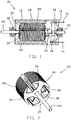
- FIG. 1 illustrates a common small size PMDC motor 10 as used, for example, in automotive accessories and battery powered applications.
- Motor 10 is shown in partial section to show the inner workings.
- Motor 10 has a cup shaped housing 12 and an end cap 14 closing the open end of the housing 12.
- the end cap 14 is typically of an insulating plastics material or has a liner of insulating plastics material which supports motor terminals 16, a pair of leaf type brush assemblies 18 and optionally other electrical components of the motor such as noise suppression components such as chokes and capacitors.
- Housing 12 accommodates a permanent magnet stator 20 and a wound rotor or armature 22.
- Armature 22 has a shaft 24 on which is mounted a commutator 26 and a armature core 28 having a number of salient poles.
- Windings 30 are formed about the salient poles and terminated on the commutator 26. Each winding 30 comprises a number of turns of insulated electrical wire forming a coil wound about respective individual poles of the core 28.
- the armature core 28 is a stack of laminations stamped from sheet electrical steel.
- the shaft 24 is journalled in bearings 32 held by the closed end of the housing 12 and by the end cap 14.
- the motor In use, the motor is operated by connecting the motor terminals to a source of suitable electrical power. Power is transferred from the terminals to the armature windings via the brush gear and commutator, the brush gear making sliding contact with the commutator as the armature rotates.
- the preferred armature is a 3 pole armature meaning that it has three salient poles 34 about which respective armature windings are wound, one winding per pole.
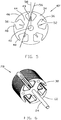
- Fig. 2 shows an unwound 3 pole armature to more clearly illustrate the structure of the core of the armature.
- the core 28 of the armature is formed from a stack of armature laminations.
- the core 28 is coated with an epoxy coating in the region of the windings, namely the axial ends and the inner surfaces of the winding tunnels 36, i.e., the spaces between adjacent poles which accommodate the windings.
- Within each winding tunnel is a radially and axially extending vane forming a winding guide 38 as will be explained hereinafter.
- FIG. 3 illustrates a preferred three pole armature lamination 40 according to the present invention.
- the lamination 40 is stamped from sheet electrical steel and has a central hole 42 for receiving the shaft. From the central region, three equally spaced poles 34 extend radially.
- Each pole 34 has a generally T-shaped configuration having a radially extending spoke 44 and a circumferentially extending cap or pole face 46.
- the ends or tips 48 of the pole face of each pole face the tips of an adjacent pole across a small gap known as the winding gap 50.
- Radially inward of the winding gap 50 is a larger space which forms a passageway in the stacked core known as the winding tunnel 36 where the windings locate as described above.
- Fingers 52 In between the pole spokes 44 are smaller radial projections known as fingers 52. Fingers 52 effectively divide the lower portion of the winding tunnel 36 into two separate sides. Thus during winding, the fingers 52 guide the wire to lay in its own half of the lower portion of the winding tunnel 36 next to the pole 34 about which the wire is being wound. When the laminations are stacked to form the core, the fingers 52 form a ridge or vane which we call the winding guide 38. Thus, when winding the wire about the adjacent poles, the wire can be wound close to the base or root of the pole spoke 44 as the previous winding has not already taken up the space at the bottom of the winding tunnel. This is shown schematically in Figure 4 when the windings are shown superimposed on the lamination of Figure 3 . Thus each winding has the same physical shape, occupies a similar space, both volume and radial location, and uses the same amount of wire. Thus the windings do not create an out of balance situation as occurs with the prior art laminations.
- the finger 52 may be of any suitable shape and size as long as it provides an effective separation between the windings and preferably, is not so large that it interferes with the operation of the normal winding machine or requires any modification of the standard winding mechanism of a winding machine.
- the thickness of the finger must be sufficient for the finger to have enough strength to withstand the force applied by the winding without deforming significantly. Of course, minor or insignificant deformation, though not desirable, could be acceptable and still offer significant improvement over the prior art.
- the present disclosure also relates to a five pole lamination 40' as shown in Fig 5 .
- the fingers 52 extend radially between the spokes 44 of the adjacent poles 34 of the lamination bisecting the space between adjacent spokes which forms the winding tunnel 36.
- the height of the fingers and thus the winding guides should be chosen so as not to interfere with the winding of the coils about the poles.
- the maximum height of the winding guide should be so that the top of the winding guide just touches a line 54 from the tip of the pole head of the pole adjacent to the pole under consideration to the adjacent tip of the pole heads of the other adjacent pole on the other side of the pole under consideration.
- Line 54 represents the feed path of the wire as it is being wound about the pole.
- Line 58 represents the radial plane bisecting the winding tunnel, which is the radial direction of the winding guide. This maximum height may be described as the intersection of line 54 with line 58.
- the height of the winding guide will be less than maximum for most applications.
- the height of the guide finger may be significantly shorter than this line.
- the height may be close to the height that touches a line 56 drawn from the tip 48 of the adjacent pole face 46 to the root 49 of the pole spoke 44.
- the root of the pole spoke is the location at which the pole spoke joins with the central region of the lamination.
- the root region is the point or area where the adjacent edge of the spoke of the initial pole joins the surface of the central region, ignoring any fillet corners or radialization of the intersection. It is the bottom or inner edge of the winding tunnel.
- the desired height of the winding guide for a five pole armature may be considered as the intersection of line 56 with line 58.
- a minimum height of the guide fingers will depend on the design of the lamination and the application, i.e., how full the winding tunnels are as the fingers are only needed to separate the adjacent windings. For motors with few windings, e.g. less than 40% fill of the tunnels, then short fingers will be sufficient but for high fill motors, e.g., 60% to 70%, then longer fingers will be required. It will be readily apparent to those skilled in the art that due to winding dynamics the radially outer portions of the windings are naturally wound closely to the pole spoke and do not require additional separation guides. Thus the fingers do not need to extend radially outwardly passed the outermost turn of each winding.
- the vane does require sufficient structural strength to resist deforming or bending under the presence of the first winding so as to not interfere with the space reserved for the second winding.
- this is a compromise as some bending can be tolerated and a completely rigid vane may be so big as to occupy a significant space in the winding tunnel originally available for the windings.
- While the disclosure relates to guide fingers formed integrally with the laminations, it is possible to implement this invention using separate guide fingers which are located within the winding tunnels during winding.
- Such separate guide fingers may be formed as part of a slot insulation arrangement or as a phase insulation arrangement or as an independent part. As an independent part, it may be left in the motor or it may be removed after winding.
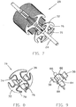
- Figure 6 shows an unwound three pole armature core fitted to the shaft.
- the armature core has a winding guide according to the present invention.
- the present disclosure relates to the winding guide being overmolded onto the armature core as an integral part of a slot liner. This is achieved by placing the core and shaft into the mold of an injection molding machine and injecting plastics material into the mold to form the slot insulation and the wire guide.
- the slot insulation is a thin layer covering the core in the area supporting or otherwise likely to contact the wires, i.e., inside surface of the winding tunnels and the axial end faces of the core. This type of slot lining is an alternative to the epoxy coating more commonly used.
- the slot liner may be formed as a separate injection molded part, complete with wire guide which is fitted to the armature core before winding. Once wound, the windings hold the lining securely to the core but before winding, the slot liner is held in place by its geometry and often by the tightness of the fit between the slot liner and the shaft.
- Figure 7 the present disclosure relates to the slot liner as shown being partially assembled to the core.
- Figure 8 is a perspective view of the slot liner of Figure 7 .
- the slot liner 70 of Figures 7 & 8 has a base portion 72 in a shape similar to the lamination and has axially extending edge parts or lips 78 which extend into the winding tunnel to protect the wires from the sharp edges of the core. This portion is also known as a spider.
- a hole 74 receives the shaft 24 as a tight fit to hold the slot liner 70 in place before winding.
- Wings 76 extend axially from the spider to cover the floor or radially inner portion of the winding tunnel. Vanes forming the winding guides 38 extend radially from the wings 76. The wings 76 gives the winding guide lateral support when fitted to the core.
- two slot liners according to the design of Figure 8 are required to insulate the armature core or to protect the windings from sharp edges of the winding tunnels, one fitted at each end and meeting in the middle.
- the two slot liners it appears necessary for the two slot liners to meet and preferably interlock to provide a complete layer of protection, this is not always necessary and a gap can exist between the confronting edges of the two liners without any concern for safety or the effectiveness of the liner or of the winding guide.
- a small gap is desired to ensure good fitting of the liner against the axial end faces of the core and to accommodate variations in the length of the core due to tolerances in the thicknesses of the individual laminations. Large gaps are also acceptable for some applications. Indeed, in the examples shown, the sides of the spokes of the inner laminations are not covered by the liner. For applications where complete coverage is necessary, the epoxy coating or overmolding alternatives are preferred.
- FIG 9 illustrates a removable winding guide assembly 80.
- the winding guide assembly 80 has a disc 82 with a central hole 84 for receiving the shaft 24.
- a boss 86 extends outwardly from the disc 82 and the hole 84 extends through the boss 86.
- Boss 86 provides additional support on the shaft and acts as a handle for installing and removing the assembly.
- Wings 88 extend axially from the disc to be located along the floor of the winding tunnel and vanes forming the winding guides 38 extend radially from the wings 88.
- the winding guide assembly 80 is inserted into the winding tunnel before winding and then removed after winding. Optionally, this may be done by a manual process.
- winding guides could be incorporated into the winding machine as part of the armature pickup/holding mechanism in which during pick up or mounting of the armature in the winding machinery, the winding guides are placed within the winding tunnels and are removed as the wound armature is removed from the winding machine.
- the winding guides it is preferred that they are made from a low friction material or coated with a low friction material to ease removal and avoid damaging the insulation on the wire of the windings which is typically an enamel insulation.
- PTFE also known by the trade name "TEFLON”.
- This invention is suited to armatures having salient poles where the armature windings are wound about individual discrete poles and not about multiple poles.
- armatures with other numbers of salient poles are known, and may be helped by this invention, we found that armatures with three poles stand to benefit the most from this invention due to the simple winding process used and the greater sensitivity to armature winding imbalance and the winding dynamics of a three pole armature.
- the winding guide divides or separates the radially inner portions of the winding tunnels into two portions.
- the purpose of this division or separation is to limit or locate the wire being wound about a salient pole, to the portion of the winding tunnels adjacent the pole about which the wire is wound.
- the winding guides keep the coils of wire of each winding wound about the adjacent poles separate, within a common winding tunnel, at least the radially inner parts.
Landscapes
- Engineering & Computer Science (AREA)
- Power Engineering (AREA)
- Manufacturing & Machinery (AREA)
- Insulation, Fastening Of Motor, Generator Windings (AREA)
- Windings For Motors And Generators (AREA)
- Iron Core Of Rotating Electric Machines (AREA)
Description
- This invention relates to small PMDC motors and in particular, to the laminations forming the core of the armature for such a motor.
- In small PMDC motors, the rotor or armature typically has a laminated core. The laminations are stamped from sheet electrical steel and stacked together to form the armature core which is pressed onto a shaft along with a commutator. The core is then placed in a winding machine where wire, typically enamel coated copper wire is wound about salient poles of the core and terminated on the commutator.
- In three pole armatures, the wires are wound around individual poles, where as for armatures with higher number of poles, the windings may be wound about groups of poles.
- In individually wound poles, the windings of adjacent poles occupy or share a common winding tunnel which is the space between adjacent poles. For armatures having a high fill rate and/or having fine wire size, the first winding to be wound may fill up the bottom of the winding tunnel spreading into the area which ideally should be occupied by the adjacent winding which is yet to be wound. Thus when the adjacent winding is wound, it is wound, at least partially, on top of the previously wound winding. This leads to a number of problems, including the second winding being larger than the first winding and the last winding is likely to be bigger yet again as it is wound between two adjacent windings. This means that although the number of turns of each winding is the same, the amount of wire used is different as the later windings are wound along a longer path. Thus the resistance of each winding will be different, which for thin and very thin wires can have an adverse effect on motor performance. Also, the greater volume of wire means that the windings are not the same weight, leading to a problem in balancing the motor, i.e., if the armature core is almost balanced before winding, after winding the armature will be significantly out of balance and when automated balancing machines are used to balance the armature, this may have an adverse effect on performance as the automatic balancing machines operate on a material removal principle and remove material from the armature core to balance the armature. The more material that is removed from the core, the bigger the effect on performance. Another important consideration, in the balance of the armature, is the radial positioning of the coils. If this is not the same, the dynamic balance of the armature will be adversely affected. By radial positioning we mean the radial distance between the axis of the armature to the center of mass of the coil. Differences in this distance between the coils of an armature will affect the dynamic balance of the armature leading to vibration in use if not corrected.
- Thus it is an object of the present invention to provide a lamination for an armature which can be wound using a winding machine which provides for separation of windings about individual poles of the armature, in a simple yet effective manner.
-
US 5 886 446 A discloses a motor including an armature withwinding guides 40.CA 2 619 583 A1 discloses a motor including partial teeth 3110. - Accordingly, the present invention provides a small PMDC motor as set out in claim 1 having a wound salient pole armature wherein the armature has a winding guide disposed within a winding tunnel formed between adjacent salient poles of the armature and arranged to separate the radially inner portion of the winding tunnels whereby windings wound about the adjacent salient poles of the armature are restrained from entering into the opposite radially inner portion of the winding tunnel.
- Preferably, the winding guide comprises a vane located within each winding tunnel, each vane extending along the winding tunnel and extending radially outwardly from a radially inner surface of the winding tunnel.
- Preferably, the vane extends along a plane bisecting the winding tunnel.
- Preferably, the vane extends radially to a height sufficient to separate the windings sharing the winding tunnel.
- Preferably, the armature core is formed of stacked laminations of electrical steel and the vanes are formed by fingers of the laminations.
- Preferably, the salient poles are substantially T-shaped having a radially extending spoke extending from a central region and a circumferentially extending pole head forming a pole face facing radially outwardly, each pole head extending between circumferentially spaced tips, a winding gap being formed between tips of adjacent pole heads and the winding tunnels being formed between the central region and the spoke and pole head of adjacent poles and being open radially through the winding gap, wherein the vanes extend along a radial plane, bisecting the winding tunnel and projecting towards the winding gap and having a radial height sufficient to separate adjacent windings within the winding tunnels but equal to or less than the height of a radial line extending through the vane and being cut by a line extending from an adjacent tip of one adjacent pole head to an adjacent tip of another adjacent pole head.
- Optionally, the radial height of the vanes is substantially equal to the height of a radial line extending through the vane and cut by a line extending from an adjacent tip of an adjacent pole head to a root region.
- Optionally, the height of the finger is approximately half of the height of the winding tunnel.
- Preferably, the winding guide is a separately formed item fitted to the armature core before winding.
- Preferably, the winding guide is of insulating material and forms an insulation barrier between adjacent windings.
- Preferably, the winding guide is an integral part of the slot insulation.
- Optionally, the slot insulation is molded directly onto the core.
- Optionally, the winding guide is a removal barrier.
- Preferably, the winding guide is at least partially formed of low friction material, especially PTFE.
- Optionally, the winding guide is a part of the winding machine.
- Preferably, the armature is a three pole armature.
- Preferred embodiments of the present invention will now be described, by way of example only, with reference to the accompanying drawings, in which:
-
Figure 1 is a PMDC motor to which the present invention is applicable; -
Figure 2 is an armature of the PMDC motor ofFigure 1 , in accordance with a preferred embodiment; -
Figure 3 is a lamination of the armature ofFigure 2 ; -
Figure 4 is a schematic sectional view showing windings superimposed on the lamination ofFigure 3 ; -
Figure 5 is a lamination for a five pole armature in accordance with another preferred embodiment of the present invention; -
Figure 6 shows an unwound core for a three pole armature with a winding guide according to another embodiment of the present invention; -
Figure 7 shows a partially exploded view of a three pole armature core with a winding guide according to a further embodiment of the present invention; -
Figure 8 is a perspective view of the winding guide ofFigure 7 ; and -
Figure 9 is a perspective view of a removable wire guide according to yet another embodiment of the present invention. -
Figure 1 illustrates a common smallsize PMDC motor 10 as used, for example, in automotive accessories and battery powered applications.Motor 10 is shown in partial section to show the inner workings. Motor 10 has a cup shapedhousing 12 and anend cap 14 closing the open end of thehousing 12. Theend cap 14 is typically of an insulating plastics material or has a liner of insulating plastics material which supportsmotor terminals 16, a pair of leaftype brush assemblies 18 and optionally other electrical components of the motor such as noise suppression components such as chokes and capacitors.Housing 12 accommodates apermanent magnet stator 20 and a wound rotor orarmature 22.Armature 22 has ashaft 24 on which is mounted acommutator 26 and aarmature core 28 having a number of salient poles.Windings 30 are formed about the salient poles and terminated on thecommutator 26. Each winding 30 comprises a number of turns of insulated electrical wire forming a coil wound about respective individual poles of thecore 28. Thearmature core 28 is a stack of laminations stamped from sheet electrical steel. Theshaft 24 is journalled inbearings 32 held by the closed end of thehousing 12 and by theend cap 14. - In use, the motor is operated by connecting the motor terminals to a source of suitable electrical power. Power is transferred from the terminals to the armature windings via the brush gear and commutator, the brush gear making sliding contact with the commutator as the armature rotates.
- The preferred armature is a 3 pole armature meaning that it has three
salient poles 34 about which respective armature windings are wound, one winding per pole.Fig. 2 shows an unwound 3 pole armature to more clearly illustrate the structure of the core of the armature. Thecore 28 of the armature is formed from a stack of armature laminations. Thecore 28 is coated with an epoxy coating in the region of the windings, namely the axial ends and the inner surfaces of the windingtunnels 36, i.e., the spaces between adjacent poles which accommodate the windings. Within each winding tunnel is a radially and axially extending vane forming a windingguide 38 as will be explained hereinafter. -
Figure 3 illustrates a preferred threepole armature lamination 40 according to the present invention. Thelamination 40 is stamped from sheet electrical steel and has acentral hole 42 for receiving the shaft. From the central region, three equally spacedpoles 34 extend radially. Eachpole 34 has a generally T-shaped configuration having aradially extending spoke 44 and a circumferentially extending cap orpole face 46. The ends ortips 48 of the pole face of each pole face the tips of an adjacent pole across a small gap known as the windinggap 50. Radially inward of the windinggap 50 is a larger space which forms a passageway in the stacked core known as the windingtunnel 36 where the windings locate as described above. - In between the
pole spokes 44 are smaller radial projections known asfingers 52.Fingers 52 effectively divide the lower portion of the windingtunnel 36 into two separate sides. Thus during winding, thefingers 52 guide the wire to lay in its own half of the lower portion of the windingtunnel 36 next to thepole 34 about which the wire is being wound. When the laminations are stacked to form the core, thefingers 52 form a ridge or vane which we call the windingguide 38. Thus, when winding the wire about the adjacent poles, the wire can be wound close to the base or root of the pole spoke 44 as the previous winding has not already taken up the space at the bottom of the winding tunnel. This is shown schematically inFigure 4 when the windings are shown superimposed on the lamination ofFigure 3 . Thus each winding has the same physical shape, occupies a similar space, both volume and radial location, and uses the same amount of wire. Thus the windings do not create an out of balance situation as occurs with the prior art laminations. - The
finger 52 may be of any suitable shape and size as long as it provides an effective separation between the windings and preferably, is not so large that it interferes with the operation of the normal winding machine or requires any modification of the standard winding mechanism of a winding machine. The thickness of the finger must be sufficient for the finger to have enough strength to withstand the force applied by the winding without deforming significantly. Of course, minor or insignificant deformation, though not desirable, could be acceptable and still offer significant improvement over the prior art. - The present disclosure also relates to a five pole lamination 40' as shown in
Fig 5 . Here again, thefingers 52 extend radially between thespokes 44 of theadjacent poles 34 of the lamination bisecting the space between adjacent spokes which forms the windingtunnel 36. - The height of the fingers and thus the winding guides should be chosen so as not to interfere with the winding of the coils about the poles. As shown in
Figure 3 , the maximum height of the winding guide should be so that the top of the winding guide just touches aline 54 from the tip of the pole head of the pole adjacent to the pole under consideration to the adjacent tip of the pole heads of the other adjacent pole on the other side of the pole under consideration.Line 54 represents the feed path of the wire as it is being wound about the pole.Line 58 represents the radial plane bisecting the winding tunnel, which is the radial direction of the winding guide. This maximum height may be described as the intersection ofline 54 withline 58. - In practice, the height of the winding guide will be less than maximum for most applications. For lamination designs with very small winding gaps or with a very low fill rate, the height of the guide finger may be significantly shorter than this line. For a five pole armature, as shown for example in
Figure 5 , the height may be close to the height that touches aline 56 drawn from thetip 48 of theadjacent pole face 46 to theroot 49 of the pole spoke 44. The root of the pole spoke is the location at which the pole spoke joins with the central region of the lamination. The root region is the point or area where the adjacent edge of the spoke of the initial pole joins the surface of the central region, ignoring any fillet corners or radialization of the intersection. It is the bottom or inner edge of the winding tunnel. As such, the desired height of the winding guide for a five pole armature may be considered as the intersection ofline 56 withline 58. - A minimum height of the guide fingers will depend on the design of the lamination and the application, i.e., how full the winding tunnels are as the fingers are only needed to separate the adjacent windings. For motors with few windings, e.g. less than 40% fill of the tunnels, then short fingers will be sufficient but for high fill motors, e.g., 60% to 70%, then longer fingers will be required. It will be readily apparent to those skilled in the art that due to winding dynamics the radially outer portions of the windings are naturally wound closely to the pole spoke and do not require additional separation guides. Thus the fingers do not need to extend radially outwardly passed the outermost turn of each winding. However, if the vanes are too short, then the windings will fall over the vanes and the winding guide will not be effective. As will be appreciated, the vane does require sufficient structural strength to resist deforming or bending under the presence of the first winding so as to not interfere with the space reserved for the second winding. Here again, this is a compromise as some bending can be tolerated and a completely rigid vane may be so big as to occupy a significant space in the winding tunnel originally available for the windings.
- While the disclosure relates to guide fingers formed integrally with the laminations, it is possible to implement this invention using separate guide fingers which are located within the winding tunnels during winding. Such separate guide fingers may be formed as part of a slot insulation arrangement or as a phase insulation arrangement or as an independent part. As an independent part, it may be left in the motor or it may be removed after winding.
-
Figure 6 shows an unwound three pole armature core fitted to the shaft. The armature core has a winding guide according to the present invention. The present disclosure relates to the winding guide being overmolded onto the armature core as an integral part of a slot liner. This is achieved by placing the core and shaft into the mold of an injection molding machine and injecting plastics material into the mold to form the slot insulation and the wire guide. The slot insulation is a thin layer covering the core in the area supporting or otherwise likely to contact the wires, i.e., inside surface of the winding tunnels and the axial end faces of the core. This type of slot lining is an alternative to the epoxy coating more commonly used. - As an alternative to overmolding, the slot liner may be formed as a separate injection molded part, complete with wire guide which is fitted to the armature core before winding. Once wound, the windings hold the lining securely to the core but before winding, the slot liner is held in place by its geometry and often by the tightness of the fit between the slot liner and the shaft. As shown in
Figure 7 the present disclosure relates to the slot liner as shown being partially assembled to the core.Figure 8 is a perspective view of the slot liner ofFigure 7 . - The
slot liner 70 ofFigures 7 & 8 has abase portion 72 in a shape similar to the lamination and has axially extending edge parts orlips 78 which extend into the winding tunnel to protect the wires from the sharp edges of the core. This portion is also known as a spider. Ahole 74 receives theshaft 24 as a tight fit to hold theslot liner 70 in place before winding.Wings 76 extend axially from the spider to cover the floor or radially inner portion of the winding tunnel. Vanes forming the windingguides 38 extend radially from thewings 76. Thewings 76 gives the winding guide lateral support when fitted to the core. - Actually, two slot liners according to the design of
Figure 8 are required to insulate the armature core or to protect the windings from sharp edges of the winding tunnels, one fitted at each end and meeting in the middle. Although it appears necessary for the two slot liners to meet and preferably interlock to provide a complete layer of protection, this is not always necessary and a gap can exist between the confronting edges of the two liners without any concern for safety or the effectiveness of the liner or of the winding guide. Indeed, a small gap is desired to ensure good fitting of the liner against the axial end faces of the core and to accommodate variations in the length of the core due to tolerances in the thicknesses of the individual laminations. Large gaps are also acceptable for some applications. Indeed, in the examples shown, the sides of the spokes of the inner laminations are not covered by the liner. For applications where complete coverage is necessary, the epoxy coating or overmolding alternatives are preferred. -
Figure 9 illustrates a removable winding guide assembly 80. The winding guide assembly 80 has adisc 82 with acentral hole 84 for receiving theshaft 24. Aboss 86 extends outwardly from thedisc 82 and thehole 84 extends through theboss 86.Boss 86 provides additional support on the shaft and acts as a handle for installing and removing the assembly.Wings 88 extend axially from the disc to be located along the floor of the winding tunnel and vanes forming the windingguides 38 extend radially from thewings 88. The winding guide assembly 80 is inserted into the winding tunnel before winding and then removed after winding. Optionally, this may be done by a manual process. Alternatively, it could be incorporated into the winding machine as part of the armature pickup/holding mechanism in which during pick up or mounting of the armature in the winding machinery, the winding guides are placed within the winding tunnels and are removed as the wound armature is removed from the winding machine. For removable winding guides, it is preferred that they are made from a low friction material or coated with a low friction material to ease removal and avoid damaging the insulation on the wire of the windings which is typically an enamel insulation. One especially suitable low friction material is PTFE, also known by the trade name "TEFLON". - This invention is suited to armatures having salient poles where the armature windings are wound about individual discrete poles and not about multiple poles. In this respect, while such armatures with other numbers of salient poles are known, and may be helped by this invention, we found that armatures with three poles stand to benefit the most from this invention due to the simple winding process used and the greater sensitivity to armature winding imbalance and the winding dynamics of a three pole armature.
- As can be appreciated from the preceding descriptions of what the present disclosure relates to, the winding guide divides or separates the radially inner portions of the winding tunnels into two portions. The purpose of this division or separation is to limit or locate the wire being wound about a salient pole, to the portion of the winding tunnels adjacent the pole about which the wire is wound. Put another way, the winding guides keep the coils of wire of each winding wound about the adjacent poles separate, within a common winding tunnel, at least the radially inner parts.
- The disclosures above are given by way of example only and various modifications will be apparent to persons skilled in the art without departing from the scope of the invention as defined in the appended claims.
Claims (8)
- A small PMDC motor having a wound salient pole armature (22) with three or five salient poles, wherein
the armature (22) has a winding guide (38) disposed within a winding tunnel (36) formed between adjacent salient poles (34) of the armature (22) and arranged to divide the radially inner portion of the winding tunnels;
characterised in that:the winding guide (38) comprises a vane located within each winding tunnel (36), each vane extending along the winding tunnel (36) and extending radially outwardly from a radial inner surface of the winding tunnel,whereby windings (30) wound about the adjacent salient poles (34) of the armature are restrained from entering into the opposite inner portion of the winding tunnel,wherein the salient poles (34) are substantially T-shaped having a radially extending spoke (44) extending from a central region and a circumferentially extending pole head forming a pole face (46) facing radially outwardly, each pole head extending between circumferentially spaced tips (48), a winding gap (50) being formed between tips (48) of adjacent pole heads and the winding tunnels (36) being formed between adjacent poles (34) where the windings are located and being open radially through the winding gap (50), wherein the vanes extend along a radial plane, bisecting the winding tunnel (36) and projecting towards the winding gap (50) and have a radial height sufficient to separate adjacent windings (30) within the winding tunnels (36), and the radial height of each vane is either:substantially equal to the height of a radial line (58) extending through the vane and being cut by a line (54) extending from the leading tip (48) of a pole head to the trailing tip of an adjacent pole head, which does not delimit the same winding tunnel (36), in the case of having three salient poles; orsubstantially equal to the height of a radial line (58) extending through the vane and being cut by a line (56) extending from the tip (48) of a pole head to the root region (49) of the spoke (44) of the adjacent pole that delimits the same winding tunnel (36), in the case of having five salient poles. - A motor according to Claim 1, wherein the armature (22) has an armature core (28) formed of stacked laminations (40,40') of electrical steel and the vanes are formed by fingers (52) of the laminations (22).
- A motor according to Claim 1, wherein the winding guide (38) is a separately formed item fitted to a core (28) of the armature (22) before winding.
- A motor according to Claim 1, wherein the winding guide (38) is of insulating material and forms an insulation barrier between adjacent windings (30).
- A motor according to Claim 1, wherein the winding guide (38) is an integral part of a slot insulation.
- A motor according to Claim 5, wherein the slot insulation is molded directly onto a core (28) of the armature (22).
- A motor according to Claim 1, wherein the winding guide (38) is a removable barrier.
- A motor according to Claim 7, wherein the winding guide (38) is at least partially formed of low friction material, especially PTFE.
Applications Claiming Priority (1)
| Application Number | Priority Date | Filing Date | Title |
|---|---|---|---|
| CN200610100197.1A CN101098090B (en) | 2006-06-30 | 2006-06-30 | Laminated sheet |
Publications (3)
| Publication Number | Publication Date |
|---|---|
| EP1873889A2 EP1873889A2 (en) | 2008-01-02 |
| EP1873889A3 EP1873889A3 (en) | 2015-09-23 |
| EP1873889B1 true EP1873889B1 (en) | 2019-11-20 |
Family
ID=38371074
Family Applications (1)
| Application Number | Title | Priority Date | Filing Date |
|---|---|---|---|
| EP07252630.4A Active EP1873889B1 (en) | 2006-06-30 | 2007-06-28 | Armature winding guide |
Country Status (4)
| Country | Link |
|---|---|
| US (1) | US8492953B2 (en) |
| EP (1) | EP1873889B1 (en) |
| JP (1) | JP5045909B2 (en) |
| CN (2) | CN104901451B (en) |
Families Citing this family (17)
| Publication number | Priority date | Publication date | Assignee | Title |
|---|---|---|---|---|
| CN104901451B (en) * | 2006-06-30 | 2019-02-05 | 德昌电机(深圳)有限公司 | Lamination |
| JP5155782B2 (en) * | 2008-09-04 | 2013-03-06 | アスモ株式会社 | Armature and motor |
| DE102009001650A1 (en) | 2009-03-19 | 2010-09-23 | Robert Bosch Gmbh | Electric machine |
| CN102025205B (en) * | 2010-08-12 | 2012-11-28 | 许晓华 | a rotor |
| JP2012222941A (en) * | 2011-04-07 | 2012-11-12 | Toyota Motor Corp | Rotating electric machine |
| DE102011121531A1 (en) * | 2011-12-16 | 2013-06-20 | Robert Bosch Gmbh | Annular rotor metal sheet for use in rotor metal sheet package of electromotor in cutting tool, has guide-type projection parts that are at large distance from center of gravity of inner edge than support-type projection parts |
| DE102012012624A1 (en) * | 2012-06-25 | 2014-01-02 | Nidec Motors & Actuators (Germany) Gmbh | Runners for electric motor, has central opening around which centering sections and mounting portions are arranged in circumferential direction at different portions of peripheral edge |
| JP2014187819A (en) * | 2013-03-25 | 2014-10-02 | Mitsuba Corp | Electric motor and wiper motor |
| US9748808B2 (en) | 2013-12-20 | 2017-08-29 | Nidec Motors & Actuators (Germany) Gmbh | Connection of rotor core assembly and rotor shaft at an electrical machine |
| CN105990979B (en) * | 2015-01-28 | 2019-09-13 | 泰安阳光动力电机有限公司 | A kind of electric exciting brushless DC motor rotor core structure |
| CN105990978A (en) * | 2015-01-28 | 2016-10-05 | 德昌电机(深圳)有限公司 | Permanent magnet DC motor |
| DE102015106523A1 (en) * | 2015-04-28 | 2016-11-03 | Ebm-Papst Mulfingen Gmbh & Co. Kg | Stator with adapted tooth geometry |
| CN107516952B (en) * | 2016-06-17 | 2020-07-28 | 德昌电机(深圳)有限公司 | Permanent-magnet DC motor |
| CN108258870A (en) * | 2016-12-29 | 2018-07-06 | 德昌电机(深圳)有限公司 | Motor and motor core |
| US11081930B2 (en) * | 2017-11-29 | 2021-08-03 | Hamilton Sundstrand Corporation | Kinetic energy storage with a switched reluctance machine |
| WO2019223253A1 (en) * | 2018-05-22 | 2019-11-28 | 上海理工大学 | Direct current motor |
| DE102024129751A1 (en) * | 2024-10-14 | 2026-04-16 | Valeo Eautomotive Germany Gmbh | Magnetic field-generating part of an electric machine, such as a stator and/or a rotor, with improved winding head end plate, as well as electric machine and vehicle with it |
Family Cites Families (45)
| Publication number | Priority date | Publication date | Assignee | Title |
|---|---|---|---|---|
| US2986663A (en) * | 1958-10-16 | 1961-05-30 | Siegler Corp | Rotor construction for dynamoelectric machines |
| JPS4112652Y1 (en) * | 1964-12-26 | 1966-06-15 | ||
| US3334255A (en) * | 1965-02-19 | 1967-08-01 | Robert W Peters | Electric motor |
| US3411725A (en) * | 1965-07-12 | 1968-11-19 | Globe Tool Eng Co | Coil winding machine |
| US3384255A (en) * | 1965-10-22 | 1968-05-21 | Clark Equipment Co | Lift attachment for handling cylindrical objects |
| US3735169A (en) * | 1971-04-04 | 1973-05-22 | Gen Electric | Channel,shaped,laminated,high temperature slot wedge for dynamoelectric machines |
| US3852137A (en) * | 1971-04-04 | 1974-12-03 | Gen Electric | Channel shaped laminated high temperature slot wedge for dynamoelectric machines |
| US4037320A (en) * | 1974-04-12 | 1977-07-26 | Gerard Edward Wilding | Apparatus for forming armature windings for commutator type dynamo/electric machines |
| GB1568704A (en) * | 1976-04-29 | 1980-06-04 | Ici Ltd | Polyester films |
| US4432135A (en) * | 1978-11-30 | 1984-02-21 | General Electric Company | Method of locking conductors in a dynamoelectric machine rotor |
| US4433262A (en) * | 1978-11-30 | 1984-02-21 | General Electric Company | Method of locking conductors in a dynamoelectric machine rotor and rotor having locked conductors |
| JPS57166860A (en) * | 1981-04-03 | 1982-10-14 | Honda Motor Co Ltd | Winding device |
| US4563808A (en) * | 1984-07-20 | 1986-01-14 | Edo Corporation | Methods of producing slotless and toothless wound stator |
| US4554491A (en) * | 1984-08-10 | 1985-11-19 | Msl Industries, Inc. | Brushless DC motor having a laminated stator with a single stator winding |
| JPH0729731Y2 (en) * | 1988-12-27 | 1995-07-05 | 株式会社三協精機製作所 | Rotating electric machine |
| US5051634A (en) | 1989-06-29 | 1991-09-24 | Kollmorgen Corporation | Motor stator heat spike |
| US5095238A (en) * | 1990-04-03 | 1992-03-10 | Minebea Co., Ltd. | Brushless dc motor and rotor magnet |
| US5274292A (en) * | 1991-09-04 | 1993-12-28 | Onan Corporation | Collector ring assembly and method |
| US5177390A (en) * | 1991-09-17 | 1993-01-05 | Kohler Co. | Rotor |
| US5444318A (en) * | 1994-02-22 | 1995-08-22 | Black & Decker Inc. | Motor with permanent magnet actuated brake |
| US5598071A (en) * | 1994-07-11 | 1997-01-28 | Seagate Technology | Method for starting and commutating a permanent-magnet direct current motor having a single phase winding |
| US6080352A (en) * | 1994-07-11 | 2000-06-27 | Seagate Technologies, Inc. | Method of magnetizing a ring-shaped magnet |
| US5705874A (en) * | 1995-05-18 | 1998-01-06 | Gerhard Geiger Gmbh & Co. | Disc for electrodynamics motors |
| EP0771061B1 (en) * | 1995-10-25 | 2003-05-07 | Sawafuji Electric Co., Ltd. | Small generator |
| US5883449A (en) * | 1996-08-07 | 1999-03-16 | Hunter Fan Company | Ceiling fan motors |
| JP3514929B2 (en) * | 1996-12-04 | 2004-04-05 | 株式会社三協精機製作所 | motor |
| JP3505345B2 (en) * | 1997-04-10 | 2004-03-08 | 株式会社三協精機製作所 | motor |
| JPH1169673A (en) * | 1997-08-09 | 1999-03-09 | Hitohiro Senoo | Rotor core for motor |
| JP3485810B2 (en) * | 1998-09-24 | 2004-01-13 | 日本電産株式会社 | Stator and motor having the same |
| GB9823924D0 (en) * | 1998-11-03 | 1998-12-30 | Lucas Ind Plc | Electric machine and rotor for use therein |
| US6342740B1 (en) * | 1998-11-06 | 2002-01-29 | Mabuchi Motor Co., Ltd. | Armature for a miniature DC motor |
| JP3574581B2 (en) * | 1999-01-29 | 2004-10-06 | マブチモーター株式会社 | Small motor |
| JP3519983B2 (en) * | 1999-04-07 | 2004-04-19 | マブチモーター株式会社 | Small motor and manufacturing method thereof |
| US6590311B1 (en) * | 1999-12-06 | 2003-07-08 | General Electric Company | Cross-shaped rotor shaft for electrical machine |
| DE60117487T2 (en) * | 2000-08-19 | 2006-10-12 | Johnson Electric S.A., La Chaux-De-Fonds | electric motor |
| MXPA03003258A (en) * | 2000-10-16 | 2004-12-03 | Globe Motors Inc | Machine for winding dynamo-electric stators. |
| US20020113519A1 (en) * | 2001-02-22 | 2002-08-22 | Brown Fred A. | Stator with molded insulator |
| JP3797122B2 (en) * | 2001-03-09 | 2006-07-12 | 株式会社日立製作所 | Permanent magnet rotating electric machine |
| US6483219B2 (en) * | 2001-03-20 | 2002-11-19 | Damco Limited | Electric motor |
| DE10392878T5 (en) * | 2002-07-02 | 2005-08-18 | Katsuyuki Totsu | Four-pole synchronous motor |
| GB0314555D0 (en) * | 2003-06-21 | 2003-07-30 | Weatherford Lamb | Electric submersible pumps |
| JP2006158136A (en) * | 2004-11-30 | 2006-06-15 | Nidec Sankyo Corp | Small motor |
| TWI307569B (en) * | 2005-01-21 | 2009-03-11 | Delta Electronics Inc | The stator structure of the motor |
| CN104901451B (en) * | 2006-06-30 | 2019-02-05 | 德昌电机(深圳)有限公司 | Lamination |
| US8207645B2 (en) * | 2009-02-24 | 2012-06-26 | Kura Laboratory Corporation | Magnetic flux controllable rotating electric machine system |
-
2006
- 2006-06-30 CN CN201510348820.4A patent/CN104901451B/en active Active
- 2006-06-30 CN CN200610100197.1A patent/CN101098090B/en active Active
-
2007
- 2007-06-28 EP EP07252630.4A patent/EP1873889B1/en active Active
- 2007-06-28 US US11/819,614 patent/US8492953B2/en active Active
- 2007-06-29 JP JP2007196711A patent/JP5045909B2/en active Active
Non-Patent Citations (1)
| Title |
|---|
| None * |
Also Published As
| Publication number | Publication date |
|---|---|
| US8492953B2 (en) | 2013-07-23 |
| CN101098090A (en) | 2008-01-02 |
| US20080001496A1 (en) | 2008-01-03 |
| CN104901451B (en) | 2019-02-05 |
| JP5045909B2 (en) | 2012-10-10 |
| CN101098090B (en) | 2015-08-12 |
| JP2008017692A (en) | 2008-01-24 |
| EP1873889A2 (en) | 2008-01-02 |
| CN104901451A (en) | 2015-09-09 |
| EP1873889A3 (en) | 2015-09-23 |
Similar Documents
| Publication | Publication Date | Title |
|---|---|---|
| US8492953B2 (en) | Lamination | |
| JP5484688B2 (en) | Armature lamination | |
| US7821175B2 (en) | Stator assembly for an electric machine and method of manufacturing the same | |
| EP2329583B1 (en) | Winding insulation arrangement for axial flux machines | |
| US7567009B2 (en) | Stator arrangement for an electric machine and a method for manufacturing the stator arrangement | |
| US20180366996A1 (en) | Brushless motor and stator therefor | |
| TWI727223B (en) | Axial gap type rotary electric machine | |
| JP4281733B2 (en) | Electric motor split stator | |
| US7342334B2 (en) | Insulated stator with wire routing element | |
| US20070194653A1 (en) | Primary Element For An Electrical Machine | |
| EP2712056A2 (en) | Stator and rotating electrical machine | |
| JP2009207334A (en) | Coil fixing member and dynamo-electric machine | |
| EP1385257A2 (en) | Method of making a stator for an electric machine | |
| JP7044871B2 (en) | Rotating electric machine and manufacturing method of rotating electric machine | |
| JP2010541258A (en) | Process and apparatus for electrically insulating coils of electrical devices | |
| JP2010104134A (en) | Rotating electrical machine | |
| JP2003143792A (en) | Armature of rotating electric machine | |
| CN218183086U (en) | Motor and motor component | |
| US20250260273A1 (en) | Rotary electric machine | |
| WO2014147810A1 (en) | Motor and manufacturing method therefor | |
| JPH1075544A (en) | Armature for rotating electric machines | |
| WO2021205653A1 (en) | Electric motor stator and electric motor |
Legal Events
| Date | Code | Title | Description |
|---|---|---|---|
| PUAI | Public reference made under article 153(3) epc to a published international application that has entered the european phase |
Free format text: ORIGINAL CODE: 0009012 |
|
| AK | Designated contracting states |
Kind code of ref document: A2 Designated state(s): AT BE BG CH CY CZ DE DK EE ES FI FR GB GR HU IE IS IT LI LT LU LV MC MT NL PL PT RO SE SI SK TR |
|
| AX | Request for extension of the european patent |
Extension state: AL BA HR MK YU |
|
| RAP1 | Party data changed (applicant data changed or rights of an application transferred) |
Owner name: JOHNSON ELECTRIC S.A. |
|
| PUAL | Search report despatched |
Free format text: ORIGINAL CODE: 0009013 |
|
| AK | Designated contracting states |
Kind code of ref document: A3 Designated state(s): AT BE BG CH CY CZ DE DK EE ES FI FR GB GR HU IE IS IT LI LT LU LV MC MT NL PL PT RO SE SI SK TR |
|
| AX | Request for extension of the european patent |
Extension state: AL BA HR MK RS |
|
| RIC1 | Information provided on ipc code assigned before grant |
Ipc: H02K 3/32 20060101AFI20150817BHEP Ipc: H02K 3/18 20060101ALN20150817BHEP Ipc: H02K 23/30 20060101ALN20150817BHEP Ipc: H02K 1/24 20060101ALI20150817BHEP |
|
| 17P | Request for examination filed |
Effective date: 20160222 |
|
| RBV | Designated contracting states (corrected) |
Designated state(s): AT BE BG CH CY CZ DE DK EE ES FI FR GB GR HU IE IS IT LI LT LU LV MC MT NL PL PT RO SE SI SK TR |
|
| AKX | Designation fees paid |
Designated state(s): AT BE BG CH CY CZ DE DK EE ES FI FR GB GR HU IE IS IT LI LT LU LV MC MT NL PL PT RO SE SI SK TR |
|
| AXX | Extension fees paid |
Extension state: RS Extension state: AL Extension state: MK Extension state: BA Extension state: HR |
|
| STAA | Information on the status of an ep patent application or granted ep patent |
Free format text: STATUS: EXAMINATION IS IN PROGRESS |
|
| 17Q | First examination report despatched |
Effective date: 20170127 |
|
| GRAP | Despatch of communication of intention to grant a patent |
Free format text: ORIGINAL CODE: EPIDOSNIGR1 |
|
| STAA | Information on the status of an ep patent application or granted ep patent |
Free format text: STATUS: GRANT OF PATENT IS INTENDED |
|
| RIC1 | Information provided on ipc code assigned before grant |
Ipc: H02K 23/30 20060101ALN20190520BHEP Ipc: H02K 3/18 20060101ALN20190520BHEP Ipc: H02K 3/32 20060101AFI20190520BHEP Ipc: H02K 1/24 20060101ALI20190520BHEP Ipc: H02K 15/095 20060101ALI20190520BHEP |
|
| INTG | Intention to grant announced |
Effective date: 20190617 |
|
| GRAS | Grant fee paid |
Free format text: ORIGINAL CODE: EPIDOSNIGR3 |
|
| GRAA | (expected) grant |
Free format text: ORIGINAL CODE: 0009210 |
|
| STAA | Information on the status of an ep patent application or granted ep patent |
Free format text: STATUS: THE PATENT HAS BEEN GRANTED |
|
| AK | Designated contracting states |
Kind code of ref document: B1 Designated state(s): AT BE BG CH CY CZ DE DK EE ES FI FR GB GR HU IE IS IT LI LT LU LV MC MT NL PL PT RO SE SI SK TR |
|
| REG | Reference to a national code |
Ref country code: GB Ref legal event code: FG4D |
|
| REG | Reference to a national code |
Ref country code: CH Ref legal event code: EP |
|
| REG | Reference to a national code |
Ref country code: IE Ref legal event code: FG4D |
|
| REG | Reference to a national code |
Ref country code: DE Ref legal event code: R096 Ref document number: 602007059515 Country of ref document: DE |
|
| REG | Reference to a national code |
Ref country code: AT Ref legal event code: REF Ref document number: 1205306 Country of ref document: AT Kind code of ref document: T Effective date: 20191215 |
|
| REG | Reference to a national code |
Ref country code: NL Ref legal event code: MP Effective date: 20191120 |
|
| REG | Reference to a national code |
Ref country code: DE Ref legal event code: R081 Ref document number: 602007059515 Country of ref document: DE Owner name: JOHNSON ELECTRIC INTERNATIONAL AG, CH Free format text: FORMER OWNER: JOHNSON ELECTRIC S.A., MURTEN, CH |
|
| REG | Reference to a national code |
Ref country code: LT Ref legal event code: MG4D |
|
| PG25 | Lapsed in a contracting state [announced via postgrant information from national office to epo] |
Ref country code: NL Free format text: LAPSE BECAUSE OF FAILURE TO SUBMIT A TRANSLATION OF THE DESCRIPTION OR TO PAY THE FEE WITHIN THE PRESCRIBED TIME-LIMIT Effective date: 20191120 Ref country code: LT Free format text: LAPSE BECAUSE OF FAILURE TO SUBMIT A TRANSLATION OF THE DESCRIPTION OR TO PAY THE FEE WITHIN THE PRESCRIBED TIME-LIMIT Effective date: 20191120 Ref country code: GR Free format text: LAPSE BECAUSE OF FAILURE TO SUBMIT A TRANSLATION OF THE DESCRIPTION OR TO PAY THE FEE WITHIN THE PRESCRIBED TIME-LIMIT Effective date: 20200221 Ref country code: BG Free format text: LAPSE BECAUSE OF FAILURE TO SUBMIT A TRANSLATION OF THE DESCRIPTION OR TO PAY THE FEE WITHIN THE PRESCRIBED TIME-LIMIT Effective date: 20200220 Ref country code: FI Free format text: LAPSE BECAUSE OF FAILURE TO SUBMIT A TRANSLATION OF THE DESCRIPTION OR TO PAY THE FEE WITHIN THE PRESCRIBED TIME-LIMIT Effective date: 20191120 Ref country code: SE Free format text: LAPSE BECAUSE OF FAILURE TO SUBMIT A TRANSLATION OF THE DESCRIPTION OR TO PAY THE FEE WITHIN THE PRESCRIBED TIME-LIMIT Effective date: 20191120 Ref country code: LV Free format text: LAPSE BECAUSE OF FAILURE TO SUBMIT A TRANSLATION OF THE DESCRIPTION OR TO PAY THE FEE WITHIN THE PRESCRIBED TIME-LIMIT Effective date: 20191120 Ref country code: ES Free format text: LAPSE BECAUSE OF FAILURE TO SUBMIT A TRANSLATION OF THE DESCRIPTION OR TO PAY THE FEE WITHIN THE PRESCRIBED TIME-LIMIT Effective date: 20191120 |
|
| PG25 | Lapsed in a contracting state [announced via postgrant information from national office to epo] |
Ref country code: IS Free format text: LAPSE BECAUSE OF FAILURE TO SUBMIT A TRANSLATION OF THE DESCRIPTION OR TO PAY THE FEE WITHIN THE PRESCRIBED TIME-LIMIT Effective date: 20200320 |
|
| PG25 | Lapsed in a contracting state [announced via postgrant information from national office to epo] |
Ref country code: RO Free format text: LAPSE BECAUSE OF FAILURE TO SUBMIT A TRANSLATION OF THE DESCRIPTION OR TO PAY THE FEE WITHIN THE PRESCRIBED TIME-LIMIT Effective date: 20191120 Ref country code: CZ Free format text: LAPSE BECAUSE OF FAILURE TO SUBMIT A TRANSLATION OF THE DESCRIPTION OR TO PAY THE FEE WITHIN THE PRESCRIBED TIME-LIMIT Effective date: 20191120 Ref country code: PT Free format text: LAPSE BECAUSE OF FAILURE TO SUBMIT A TRANSLATION OF THE DESCRIPTION OR TO PAY THE FEE WITHIN THE PRESCRIBED TIME-LIMIT Effective date: 20200412 Ref country code: EE Free format text: LAPSE BECAUSE OF FAILURE TO SUBMIT A TRANSLATION OF THE DESCRIPTION OR TO PAY THE FEE WITHIN THE PRESCRIBED TIME-LIMIT Effective date: 20191120 Ref country code: DK Free format text: LAPSE BECAUSE OF FAILURE TO SUBMIT A TRANSLATION OF THE DESCRIPTION OR TO PAY THE FEE WITHIN THE PRESCRIBED TIME-LIMIT Effective date: 20191120 |
|
| REG | Reference to a national code |
Ref country code: AT Ref legal event code: MK05 Ref document number: 1205306 Country of ref document: AT Kind code of ref document: T Effective date: 20191120 |
|
| REG | Reference to a national code |
Ref country code: DE Ref legal event code: R097 Ref document number: 602007059515 Country of ref document: DE |
|
| PG25 | Lapsed in a contracting state [announced via postgrant information from national office to epo] |
Ref country code: SK Free format text: LAPSE BECAUSE OF FAILURE TO SUBMIT A TRANSLATION OF THE DESCRIPTION OR TO PAY THE FEE WITHIN THE PRESCRIBED TIME-LIMIT Effective date: 20191120 |
|
| PLBE | No opposition filed within time limit |
Free format text: ORIGINAL CODE: 0009261 |
|
| STAA | Information on the status of an ep patent application or granted ep patent |
Free format text: STATUS: NO OPPOSITION FILED WITHIN TIME LIMIT |
|
| 26N | No opposition filed |
Effective date: 20200821 |
|
| PG25 | Lapsed in a contracting state [announced via postgrant information from national office to epo] |
Ref country code: AT Free format text: LAPSE BECAUSE OF FAILURE TO SUBMIT A TRANSLATION OF THE DESCRIPTION OR TO PAY THE FEE WITHIN THE PRESCRIBED TIME-LIMIT Effective date: 20191120 Ref country code: PL Free format text: LAPSE BECAUSE OF FAILURE TO SUBMIT A TRANSLATION OF THE DESCRIPTION OR TO PAY THE FEE WITHIN THE PRESCRIBED TIME-LIMIT Effective date: 20191120 Ref country code: SI Free format text: LAPSE BECAUSE OF FAILURE TO SUBMIT A TRANSLATION OF THE DESCRIPTION OR TO PAY THE FEE WITHIN THE PRESCRIBED TIME-LIMIT Effective date: 20191120 |
|
| PG25 | Lapsed in a contracting state [announced via postgrant information from national office to epo] |
Ref country code: IT Free format text: LAPSE BECAUSE OF FAILURE TO SUBMIT A TRANSLATION OF THE DESCRIPTION OR TO PAY THE FEE WITHIN THE PRESCRIBED TIME-LIMIT Effective date: 20191120 Ref country code: MC Free format text: LAPSE BECAUSE OF FAILURE TO SUBMIT A TRANSLATION OF THE DESCRIPTION OR TO PAY THE FEE WITHIN THE PRESCRIBED TIME-LIMIT Effective date: 20191120 |
|
| REG | Reference to a national code |
Ref country code: CH Ref legal event code: PL |
|
| GBPC | Gb: european patent ceased through non-payment of renewal fee |
Effective date: 20200628 |
|
| PG25 | Lapsed in a contracting state [announced via postgrant information from national office to epo] |
Ref country code: LU Free format text: LAPSE BECAUSE OF NON-PAYMENT OF DUE FEES Effective date: 20200628 |
|
| REG | Reference to a national code |
Ref country code: BE Ref legal event code: MM Effective date: 20200630 |
|
| PG25 | Lapsed in a contracting state [announced via postgrant information from national office to epo] |
Ref country code: GB Free format text: LAPSE BECAUSE OF NON-PAYMENT OF DUE FEES Effective date: 20200628 Ref country code: FR Free format text: LAPSE BECAUSE OF NON-PAYMENT OF DUE FEES Effective date: 20200630 Ref country code: IE Free format text: LAPSE BECAUSE OF NON-PAYMENT OF DUE FEES Effective date: 20200628 Ref country code: LI Free format text: LAPSE BECAUSE OF NON-PAYMENT OF DUE FEES Effective date: 20200630 Ref country code: CH Free format text: LAPSE BECAUSE OF NON-PAYMENT OF DUE FEES Effective date: 20200630 |
|
| PG25 | Lapsed in a contracting state [announced via postgrant information from national office to epo] |
Ref country code: BE Free format text: LAPSE BECAUSE OF NON-PAYMENT OF DUE FEES Effective date: 20200630 |
|
| PG25 | Lapsed in a contracting state [announced via postgrant information from national office to epo] |
Ref country code: TR Free format text: LAPSE BECAUSE OF FAILURE TO SUBMIT A TRANSLATION OF THE DESCRIPTION OR TO PAY THE FEE WITHIN THE PRESCRIBED TIME-LIMIT Effective date: 20191120 Ref country code: MT Free format text: LAPSE BECAUSE OF FAILURE TO SUBMIT A TRANSLATION OF THE DESCRIPTION OR TO PAY THE FEE WITHIN THE PRESCRIBED TIME-LIMIT Effective date: 20191120 Ref country code: CY Free format text: LAPSE BECAUSE OF FAILURE TO SUBMIT A TRANSLATION OF THE DESCRIPTION OR TO PAY THE FEE WITHIN THE PRESCRIBED TIME-LIMIT Effective date: 20191120 |
|
| P01 | Opt-out of the competence of the unified patent court (upc) registered |
Effective date: 20230628 |
|
| PGFP | Annual fee paid to national office [announced via postgrant information from national office to epo] |
Ref country code: DE Payment date: 20250626 Year of fee payment: 19 |