EP1873686A2 - Biometrics device - Google Patents
Biometrics device Download PDFInfo
- Publication number
- EP1873686A2 EP1873686A2 EP07011911A EP07011911A EP1873686A2 EP 1873686 A2 EP1873686 A2 EP 1873686A2 EP 07011911 A EP07011911 A EP 07011911A EP 07011911 A EP07011911 A EP 07011911A EP 1873686 A2 EP1873686 A2 EP 1873686A2
- Authority
- EP
- European Patent Office
- Prior art keywords
- finger
- image
- light sources
- images
- venous
- Prior art date
- Legal status (The legal status is an assumption and is not a legal conclusion. Google has not performed a legal analysis and makes no representation as to the accuracy of the status listed.)
- Withdrawn
Links
Images



Classifications
-
- G—PHYSICS
- G06—COMPUTING OR CALCULATING; COUNTING
- G06V—IMAGE OR VIDEO RECOGNITION OR UNDERSTANDING
- G06V40/00—Recognition of biometric, human-related or animal-related patterns in image or video data
- G06V40/10—Human or animal bodies, e.g. vehicle occupants or pedestrians; Body parts, e.g. hands
- G06V40/12—Fingerprints or palmprints
- G06V40/1335—Combining adjacent partial images (e.g. slices) to create a composite input or reference pattern; Tracking a sweeping finger movement
-
- G—PHYSICS
- G06—COMPUTING OR CALCULATING; COUNTING
- G06V—IMAGE OR VIDEO RECOGNITION OR UNDERSTANDING
- G06V40/00—Recognition of biometric, human-related or animal-related patterns in image or video data
- G06V40/10—Human or animal bodies, e.g. vehicle occupants or pedestrians; Body parts, e.g. hands
- G06V40/12—Fingerprints or palmprints
- G06V40/13—Sensors therefor
- G06V40/1318—Sensors therefor using electro-optical elements or layers, e.g. electroluminescent sensing
-
- G—PHYSICS
- G06—COMPUTING OR CALCULATING; COUNTING
- G06V—IMAGE OR VIDEO RECOGNITION OR UNDERSTANDING
- G06V40/00—Recognition of biometric, human-related or animal-related patterns in image or video data
- G06V40/10—Human or animal bodies, e.g. vehicle occupants or pedestrians; Body parts, e.g. hands
- G06V40/14—Vascular patterns
Definitions
- An object of the present invention is to provide a less expensive and more compact biometrics device.
- a luminous energy adjusting unit which adjusts the luminous energy of the reflective light sources arranged in a substantially horizontal direction, wherein, after the luminous energy outputs of the reflective light sources have been stabilized, the imaging unit picks up and acquires an image of the finger for authentication processing.
- a low-cost and compact vein authentication device since it enables image information on a living body to be acquired processed while moving it, a low-cost and compact vein authentication device can be realized. Further, a constant venous image pattern can be obtained even if the sweeping velocity varies.
- the structure is such that the roller 5 and the lead screw 6 are fixed to their respective rotation shafts 40 parallel to each other and are mutually interlocked via linking gears 41.
- the lead screw 6 is provided with colored grooves 17 at prescribed intervals to clearly measure the sweep quantity. These grooves 17 are colored black and do not reflect the light from the auxiliary light source 7. Other grooves do reflect the light from the auxiliary light source 7. In the input images, the colored grooves 17 are seen as black images as shown in Fig. 5.
- Fig. 4 shows the stored contents of the memory 9 of the authentication processing unit 8.
- Fig. 11 shows the stored contents of the memory 9.
- the venous image data 32 stores data after the processing to paste an image equivalent to the travel distance cut out of the venous image 32B onto the venous image 32A. For instance, this processing is accomplished by computing the travel distance 39 in the x-axis direction and the travel distance 90 in the y-axis direction by comparing the characteristic points of a surface image 37A which constitutes the n-th input image and of a surface image 37B which constitutes the (n+1) -th input, cutting an image equivalent to the travel distance out of the venous image 32B and pasting it onto the venous image 32A.
Landscapes
- Engineering & Computer Science (AREA)
- Human Computer Interaction (AREA)
- Physics & Mathematics (AREA)
- General Physics & Mathematics (AREA)
- Multimedia (AREA)
- Theoretical Computer Science (AREA)
- Health & Medical Sciences (AREA)
- General Health & Medical Sciences (AREA)
- Vascular Medicine (AREA)
- Measurement Of The Respiration, Hearing Ability, Form, And Blood Characteristics Of Living Organisms (AREA)
- Image Input (AREA)
- Collating Specific Patterns (AREA)
Abstract
Description
- The present invention relates to a biometrics device, and more particularly to a vein authentication device which authenticates individuals by use of venous information obtained by sweeping finger veins.
- Development of authentication devices as a technique for authenticating individuals by use of biometric information is making progress, and such devices are now coming into practical use in PCs, mobile terminals, automatic telling machines (ATMs) and automobiles. The working principle of vein authentication devices is that a living body is irradiated with near infrared rays, and the rays which are scattered within the body and later transmitted outside the body are formed into a biometric image. As hemoglobin in the blood absorbs near infrared rays, it emerges in the formed image as a dark shadowy pattern, and thereby enables veins to be recognized as such shadowy patterns. A vein authentication device authenticates an individual by computing the correlation between the imaged pattern and a pertinent pattern in biometric information images registered in advance.
- Known vein authentication devices as such include, for instance, those disclosed in
JP-A-253989/2005 JP-A-235049/2005 - Conventional vein authentication devices inevitably have to be structured in larger dimensions than the living objects because of the need to acquire overall information on the objects to be measures. However, larger authentication devices are correspondingly more costly and may be restricted in mounting convenience. Therefore, more compact vein authentication devices are called for.
- An object of the present invention is to provide a less expensive and more compact biometrics device.
- Another object of the invention is to provide a vein authentication device which, when biometric information is to be acquired by having a living body sweep, can provide a constant venous image pattern even if the sweeping velocity varies.
- Preferably, the invention is configured as a biometrics device including a supporting mechanism which movably supports a living body, light sources which emit near infrared rays, an imaging unit which picks up venous images of the living body with light emitted from the light sources and an image processing unit which processes venous images picked up by the imaging unit, wherein the imaging unit picks up a plurality of still images consecutively from the living body which travels supported by the supporting mechanism and the image processing unit forms an image pattern of the living body by subjecting the obtained plurality of still images to processing.
- In a preferable example, the supporting mechanism has a roller over which a finger is to be placed and a lead screw which turns interlocked with the roller, the lead screw is illuminated with light from the light sources, and the imaging unit obtains still images of the lead screw and venous images of the finger.
- Preferably, predetermined positions on the lead screw are marked, and the image processing unit, computing travel distances of the finger with reference to those marks in the still images obtained, processes combination of each plurality of still images of the finger obtained from the imaging unit by use of the computed travel distances.
- Another preferable example of the invention is configured as a biometrics device including a supporting mechanism which movably supports a living body, light sources which emit near infrared rays, reflective light sources which are arranged in a substantially horizontal direction, an imaging unit which picks up a plurality of venous images and a plurality of surface images of the living body while alternately causing the reflective light sources and the light sources of near infrared rays to emit light, and an image processing unit which computes travel distances of characteristic points of the surface images from the plurality of surface images obtained and processes combination of the plurality of venous images into a single image pattern. Preferably, it is further equipped with a luminous energy adjusting unit which adjusts the luminous energy of the reflective light sources arranged in a substantially horizontal direction, wherein, after the luminous energy outputs of the reflective light sources have been stabilized, the imaging unit picks up and acquires an image of the finger for authentication processing.
- According to the invention, since it enables image information on a living body to be acquired processed while moving it, a low-cost and compact vein authentication device can be realized. Further, a constant venous image pattern can be obtained even if the sweeping velocity varies.
- Preferred embodiments of the present invention will now be described in conjunction with the accompanying drawings, in which:
- Fig. 1 shows a profile of an
image input unit 1 of a vein authentication device, which is a first embodiment of the invention; - Fig. 2 shows the internal structure of the
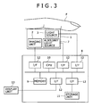
image input unit 1 in the first preferred embodiment of the invention; - Fig. 3 is a configurational diagram of the vein authentication device, which is the first embodiment of the invention;
- Fig. 4 shows contents stored in a
memory 9 of anauthentication processing unit 8 in the first embodiment of the invention; - Fig. 5 shows an initial input screen in the first embodiment of the invention;
- Fig. 6 shows an input image after a finger has traveled away in the first embodiment of the invention;
- Figs. 7A and 7B are intended for use in the description of vein image pasting in the first embodiment of the invention;
- Fig. 8 shows a profile of the
image input unit 1 in a second preferred embodiment of the invention; - Fig. 9 shows a top view of the
image input unit 1 in the second preferred embodiment of the invention; - Fig. 10 shows a venous image of a finger in the second embodiment of the invention;
- Fig. 11 shows contents stored in the
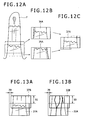
memory 9 of theauthentication processing unit 8 in the second embodiment of the invention; - Figs. 12A to 12C are intended for use in the description of the generation of a finger surface image in the second embodiment of the invention; and
- Figs. 13A and 13B illustrate how a venous image of a finger is formed from its surface image in the second embodiment of the invention.
- Preferred embodiments of the present invention will be described below with reference to the drawings.
- First, the first preferred embodiment of the invention will be described with reference to Figs. 1 through 7B.
- Fig. 1 shows a profile of the
image input unit 1 of a vein authentication device and Fig. 2 shows its plan. Theimage input unit 1 haslight sources 3 arranged in two positions and emitting near infrared rays, animaging unit 2 which picks up venous images of a finger F with light from thelight sources 3, aroller 5 which turns mounted with the finger F, alead screw 6 which turns interlocked with thisroller 5, and anauxiliary light source 7 which illuminates thelead screw 6. - As shown in Fig. 2, the structure is such that the
roller 5 and thelead screw 6 are fixed to theirrespective rotation shafts 40 parallel to each other and are mutually interlocked via linkinggears 41. Thelead screw 6 is provided withcolored grooves 17 at prescribed intervals to clearly measure the sweep quantity. Thesegrooves 17 are colored black and do not reflect the light from theauxiliary light source 7. Other grooves do reflect the light from theauxiliary light source 7. In the input images, thecolored grooves 17 are seen as black images as shown in Fig. 5. - It is preferable here for the widthwise shape of the
roller 5 to be substantially equal to the width of the finger F to be placed over it. This enables the placing position of the finger F of the object to be clearly defined and the sweep of the finger F to be guided to linearity. Also,grooves 51 matched in shape with the finger F are formed in theroller 5, and thesegrooves 51 can prevent veins from being flattened. - Incidentally, though two
light sources 3 are arranged in the illustrated case to pick up clear venous images, onelight source 3 will suffice if proper images can be obtained. - As shown in Fig. 3, the vein authentication device is configured of an
image input unit 1 and anauthentication processing unit 8. Theauthentication processing unit 8 has aCPU 10, amemory 9, astorage unit 11, adisplay unit 13 andinterfaces 12. TheCPU 10 here performs various processing functions by executing programs stored in thememory 9. The functions of these programs will be described afterwards. Thememory 9 also stores image data acquired by theimaging unit 2. Thestorage unit 11 stores predetermined venous image data. Theinterfaces 12 connect theimaging unit 2, thestorage unit 11 and theimage input unit 1. - The
display unit 13 is connected to theauthentication processing unit 8 to display situations including the result of authentication. Incidentally, thisdisplay unit 13 is dispensable. Where it is dispensed with, the result of authentication is made known by an alarm and the like. - Fig. 4 shows the stored contents of the
memory 9 of theauthentication processing unit 8. - The programs stored in the
memory 9 include a leadscrew detection program 18 for detecting and computing the quantities of variation of the lead screw image, an imagedata pasting program 24 for composing (pasting together) a biometric image on the basis of the quantities of variation computed according to the leadscrew detection program 18, and acharacteristics collation program 21 for extracting characteristics ofbiometric information data 23, collating them with a group of characteristic data registered in thestorage unit 11 in advance and determining whether or not thebiometric information data 23 is valid. The sets of data stored includeinput image data 15 and thebiometric information data 23. - Next, the authentication processing by the vein authentication device of this embodiment will be described with reference to Figs. 5 through 7B.
- As the image picked up from the initial state, an image of the
lead screw 6 is picked up keeping only the auxiliarylight source 7 lit. In this state, the positions of thegrooves 17 in thelead screw 6 are detected and monitored by theauthentication processing unit 8. Next, when the finger F is placed over theroller 5, the image of thegrooves 17 picked up by theimaging unit 2 varies. By causing theauthentication processing unit 8 to recognize this, thelight sources 3 are lit to start vein authentication processing. Or, it may be recognized by the method disclosed inPatent Reference 2 that the relative brightness of the input image has surpassed or fallen below a threshold, and thelight sources 3 are lit accordingly. - When the
light sources 3 are lit, the finger F is irradiated with near infrared rays. The light scattered within the finger F is picked up as animage 15A containing avenous image 14A and alead screw image 16A by the imaging unit 2 (Fig. 5) . The picked-up image of the finger is stored into the area for theinput image data 15 in thememory 9 as the initial input image via theinterface 12. Correspondingly to thisimage 15A, theCPU 10 is caused to store thevenous image 14A into the area for thebiometric information data 23, and at the same time the positions of thegrooves 17 of thelead screw image 16A are recognized. - In this while, the finger of the object is traveling over the
roller 5 from its position in the initial state. - An
image 15B to be picked up next is an image after a travel relative to theinitial image 15A. Thisimage 15B is shown in Fig. 6. - The
CPU 10 cuts alead screw image 16B out of theimage 15B, detects atravel distance 19 of thegrooves 17 and computes the travel distance 20 (Figs. 7A and 7B) from the initialvenous image 14B. Avenous image 14C equivalent to thetravel distance 20 is thereby pasted onto thebiometric information data 23. As the state of the pastedbiometric information 23 shown in Fig. 7B indicates, theearlier image 14A and the subsequently acquiredimage 14C are pasted together. - This processing is executed in the following manner. For instance, input image data (n) are inputted, and a lead screw image 16(n) is cut out of the input image data (n). Next, it is compared with a lead screw image 16 (n-1) and a travel distance 19 (n) is detected. And a travel distance 20 (n) is computed from the travel distance 19(n), and a venous image 14(n) in input image data 15(n) is cut out in an equivalent to the travel distance 20 (n) for the biometric information data 23 (n-1) and pasted onto a venous image 14 (n-1) . After that, the processing shifts to inputting of input image data (n+1).
- As the
travel distance 19 of thegrooves 17 here is in direct proportion to thetravel distance 20 from thevenous image 14A to thevenous image 14B, theCPU 10 can process pasting by merely performing simple computation of adding or subtracting the overlapping part of the pasting. This enables the required computation of the travel distances of images to be significantly reduced. Further, it is made possible, when pasting thevenous image 14C, to correct the pasting position of the venous image 13C by comparing and collating the remaining part of thevenous image 14B after the removal of the venous image 13C with thevenous image data 14A stored in thebiometric information 23, thereby enabling more accurate image pasting to be processed. - By repeating the processing described so far,
venous information 22 on the whole finger F which is the obj ect is stored into the biometricinformation data area 23. This processing makes it possible to check whether or not the generatedbiometric information data 23 matches the pertinent person by executing thecharacteristics collation program 21 and thereby comparing and collating it with a pattern stored in thestorage unit 11. - Next, a second embodiment of the present invention will be described with reference to Fig. 8 and subsequent drawings.
- As shown in Fig. 8, the second embodiment of the invention has reflective
light sources 31 for a living body in itsimage input unit 30. Compared with theimage input unit 1 shown in Figs. 1 through 3, it has the same configuration as the vein authentication device of the first embodiment except for the absence of the auxiliarylight source 7, and the same parts will be assigned respectively the same reference signs. Duplication of a description will be dispensed with. - As shown in Fig. 9, in order to more clearly image the shades of the unevenness of the finger F,
reflective light sources reflective light sources reflective light sources 31 here to be long-wavelength blue LEDs in order to obtain the surface image of the finger F clearly, other visible light may as well be used if the image can be obtained clearly. - As a surface image is obtained by irradiation from the two
reflective light sources surface image data 35 and leftsurface image data 36 are also secured for the data to be stored in thememory 9 as shown in Fig. 11. - Fig. 10 shows acquired finger vein image data, wherein
reference sign 32A denotes venous image data inputted for the n-th time and 32B denotes venous image data inputted for the (n+1)-th time. - Fig. 11 shows the stored contents of the
memory 9. - A
characteristics extraction program 33 extracts characteristic points of input images (venous image, right surface image and left surface image). An imagedata pasting program 34 realizes the function of detecting the travel distance of image data from the characteristic points extracted from thecharacteristics extraction program 33, correcting the travel distance and pasting the image data. - Right
surface image data 35 stores the right half of the image, and leftsurface image data 36 stores the left half.Surface image data 37 stores image data resulting from the processing to correct the travel distance of the image according to the characteristic points of theright surface image 35 and of theleft surface image 36 which have been cut out. - The
venous image data 32 stores data after the processing to paste an image equivalent to the travel distance cut out of thevenous image 32B onto thevenous image 32A. For instance, this processing is accomplished by computing thetravel distance 39 in the x-axis direction and thetravel distance 90 in the y-axis direction by comparing the characteristic points of asurface image 37A which constitutes the n-th input image and of asurface image 37B which constitutes the (n+1) -th input, cutting an image equivalent to the travel distance out of thevenous image 32B and pasting it onto thevenous image 32A. - A
characteristics collation program 38 compares afinger vein image 41 finished by the imagedata pasting program 34 with a group of characteristic data registered in thestorage unit 11 in advance, and determines whether or not thefinger vein image 41 is valid. - Next, a method of acquiring the venous image of the finger F using this embodiment will be described.
- When the finger F is placed over the
image input unit 30, the finger F is imaged first with thelight sources 3 and thereflective light sources authentication processing unit 8 checks whether or not the contour of the finger F can be distinguished or whether or not the image is free from halation, and the optimal luminous energy is set for each light source. - After this setting has been completed, the
light sources 3 are lit to pick up a one-frame equivalent of thevenous image 32A, which is stored into thevenous image data 32 in thememory 9 via theinterface 12, and theCPU 10 processes extraction of characteristics of the venous image data. Next, thelight sources 3 are turned off, the reflectivelight source 31A is turned on to pick up a one-frame equivalent of asurface image 35A, which is stored into the rightsurface image data 35 in thememory 9 via theinterface 12, followed by similar processing to extract characteristics. - Then, the reflective
light source 31A is turned off, and the reflectivelight sources 31B to pick up a one-frame equivalent of asurface image 36A, which is stored into the leftsurface image data 36 in thememory 9 via theinterface 12 to be subjected to processing to extract characteristics. Since there is a time lag equivalent to one frame between the rightsurface image data 35 and the leftsurface image data 36, the lag is compensated for by collating characteristic points extracted from the respective central parts of the images of the rightsurface image data 35 and the leftsurface image data 36. Further, the center is extracted from the finger contour of the left right surface image, and thesurface image 37A of the finger F can be formed by pasting together the right half of theright surface image 35 and the left half of the left surface image 36 (Figs. 12A to 12C). - By repeating the processing described so far, the
venous images 32B and thesurface images 37B of the second and subsequent frames can be obtained. How this is accomplished is shown in Figs. 13A and 13B. Since more characteristics can be extracted here from a surface image than from a venous image, by comparing thesurface images 37A and thesurface images 37B with the sweeping method, thetravel distance 90 of the finger F in the vertical direction can be computed. Further, as thetravel distance 39 in the horizontal direction, which is the positional lag in the right-and-left direction, can also be detected on the basis of contour extraction or detected data of characteristic points of the finger F, it is made possible to paste together thevenous image 32A and thevenous image 32B with high accuracy after the venous images by use of this data and pasting them together. - Since the travel distance can be consecutively computed from the surface images of the finger F by repeating the processing described so far, it is made possible to obtain venous images matching the computed travel distances, to obtain the overall venous image and characteristic point data of the finger F with high accuracy by pasting them together, and thereby to acquire overall venous image data 91 of the finger F to be authenticated. The overall venous image data 91 so acquired is compared and collated with a pattern stored in the
storage unit 11 by executing thecharacteristics collation program 38. As a result of this collation, it can be checked whether or not the acquired venous image data 91 fits the legitimate person. - Further, when surface image information on the finger F is to be authenticated, if the travel distance can be adequately computed from only the left surface image or the right surface image, only one side image will suffice, and in this case, the cost can be saved and the time taken to process computation can be reduced.
- This embodiment of the invention, since it requires no addition of any particular encoder mechanism and can measure the travel distance of sweeping by a living body, a low-cost and compact vein authentication device can be realized.
Claims (9)
- A biometrics device comprising a supporting mechanism which movably supports a living body, light sources which emit near infrared rays, an imaging unit which picks up venous images of the living body with light emitted from the light sources and an image processing unit which processes venous images picked up by the imaging unit, wherein the imaging unit picks up a plurality of still images consecutively from the living body which travels supported by the supporting mechanism and the image processing unit forms an image pattern of the living body by subjecting the obtained plurality of still images to processing.
- The vein authentication device according to Claim 1, wherein the supporting mechanism has a roller over which a finger is to be placed and a lead screw which turns interlocked with the roller, the lead screw is illuminated with light from the light sources, and the imaging unit obtains still images of the lead screw and venous images of the finger.
- The finger vein authentication device according to Claim 2, wherein the widthwise shape of the roller is substantially equal to the width of a human finger and grooves are cut therein.
- The vein authentication device according to Claim 2, wherein predetermined positions on the lead screw are marked, and the image processing unit, computing the travel distances of the finger with reference to those marks in the still images obtained, processes combination of each plurality of still images of the finger obtained from the imaging unit by use of the computed travel distances.
- The vein authentication device according to Claim 3, wherein predetermined positions on the lead screw are marked, and the image processing unit, computing travel distances of the finger with reference to those marks in the still images obtained, processes combination of each plurality of still images of the finger obtained from the imaging unit by use of the computed travel distances.
- A biometrics device comprising a supporting mechanism which movably supports a living body, light sources which emit near infrared rays, reflective light sources which are arranged in a substantially horizontal direction, an imaging unit which picks up a plurality of venous images and a plurality of surface images of the living body while alternately causing the reflective light sources and the light sources of near infrared rays to emit light, and an image processing unit which computes travel distances of characteristic points of the surface images from the plurality of surface images obtained and processes the plurality of venous images into a single image pattern.
- The finger vein authentication device according to Claim 6, further equipped with a luminous energy adjusting unit which adjusts the luminous energy of the reflective light sources arranged in a substantially horizontal direction, wherein, after the luminous energy outputs of the reflective light sources have been stabilized, the imaging unit picks up and acquires an image of the finger for authentication processing.
- The finger vein authentication device according to Claim 6, wherein the reflective light sources are blue LEDs.
- The finger vein authentication device according to Claim 7, wherein the reflective light sources are blue LEDs.
Applications Claiming Priority (1)
| Application Number | Priority Date | Filing Date | Title |
|---|---|---|---|
| JP2006175006A JP4659688B2 (en) | 2006-06-26 | 2006-06-26 | Biometric authentication device |
Publications (2)
| Publication Number | Publication Date |
|---|---|
| EP1873686A2 true EP1873686A2 (en) | 2008-01-02 |
| EP1873686A3 EP1873686A3 (en) | 2012-03-21 |
Family
ID=38520698
Family Applications (1)
| Application Number | Title | Priority Date | Filing Date |
|---|---|---|---|
| EP07011911A Withdrawn EP1873686A3 (en) | 2006-06-26 | 2007-06-18 | Biometrics device |
Country Status (6)
| Country | Link |
|---|---|
| US (1) | US7991205B2 (en) |
| EP (1) | EP1873686A3 (en) |
| JP (1) | JP4659688B2 (en) |
| KR (1) | KR20070122400A (en) |
| CN (1) | CN101097599B (en) |
| TW (1) | TW200800107A (en) |
Families Citing this family (14)
| Publication number | Priority date | Publication date | Assignee | Title |
|---|---|---|---|---|
| JP4547629B2 (en) * | 2006-02-10 | 2010-09-22 | ソニー株式会社 | Registration device, registration method, and registration program |
| JP4659688B2 (en) * | 2006-06-26 | 2011-03-30 | 日立オムロンターミナルソリューションズ株式会社 | Biometric authentication device |
| JP5292821B2 (en) * | 2008-01-16 | 2013-09-18 | ソニー株式会社 | Vein image acquisition device and vein image acquisition method |
| JP2010015365A (en) * | 2008-07-03 | 2010-01-21 | Hitachi Maxell Ltd | Biometrics device and biometrics method |
| WO2010041731A1 (en) * | 2008-10-10 | 2010-04-15 | 日本電気株式会社 | Collating device, collating method, and program |
| JP2011243042A (en) * | 2010-05-19 | 2011-12-01 | Nec Corp | Organism imaging device and method |
| CN103985201A (en) * | 2014-05-22 | 2014-08-13 | 昆山古鳌电子机械有限公司 | Paper money transaction system |
| WO2016090614A1 (en) * | 2014-12-11 | 2016-06-16 | 陈银芳 | Scanning circuit structure of intelligent mobile terminal |
| KR102349959B1 (en) * | 2015-01-07 | 2022-01-11 | 삼성전자주식회사 | Bio signal measurement apparatus and bio signal measurement method |
| USD776664S1 (en) * | 2015-05-20 | 2017-01-17 | Chaya Coleena Hendrick | Smart card |
| CN105512644B (en) * | 2016-01-15 | 2020-04-24 | 福建省宜品生物科技有限公司 | Finger vein recognition device and recognition method thereof |
| CN107766775A (en) * | 2016-08-17 | 2018-03-06 | 广州广电运通金融电子股份有限公司 | A kind of finger vena acquisition method and device |
| CN111652088B (en) * | 2020-05-15 | 2023-06-20 | 圣点世纪科技股份有限公司 | Finger vein registration method and registration device based on video optimization mechanism |
| CN112052764A (en) * | 2020-08-27 | 2020-12-08 | 五邑大学 | A palm vein identification device, method and storage medium |
Family Cites Families (27)
| Publication number | Priority date | Publication date | Assignee | Title |
|---|---|---|---|---|
| JPH04199376A (en) * | 1990-11-29 | 1992-07-20 | Fujitsu Ltd | Finger print image input device |
| CN1364279A (en) * | 2000-03-08 | 2002-08-14 | 精工电子有限公司 | Image reader |
| US7113622B2 (en) * | 2001-06-27 | 2006-09-26 | Laurence Hamid | Swipe imager with improved sensing control features |
| US7272248B2 (en) * | 2001-07-16 | 2007-09-18 | Activcard Ireland Limited | Biometric imaging device compensating for non-biometric parameters |
| DE60225224D1 (en) * | 2001-11-14 | 2008-04-10 | Hitachi Ltd | System for starting an engine using biometric information |
| US6954260B2 (en) * | 2002-01-17 | 2005-10-11 | Cross Match Technologies, Inc. | Systems and methods for illuminating a platen in a print scanner |
| EP1353292B1 (en) * | 2002-04-12 | 2011-10-26 | STMicroelectronics (Research & Development) Limited | Biometric sensor apparatus and methods |
| JP3972779B2 (en) * | 2002-09-20 | 2007-09-05 | 株式会社日立製作所 | Personal authentication device |
| US7480397B2 (en) * | 2003-04-18 | 2009-01-20 | Casio Computer Co., Ltd. | Fingerprint image reading apparatus |
| US7200250B2 (en) * | 2003-05-20 | 2007-04-03 | Lightuning Tech, Inc. | Sweep-type fingerprint sensor module |
| JP4207717B2 (en) * | 2003-08-26 | 2009-01-14 | 株式会社日立製作所 | Personal authentication device |
| TW200517975A (en) * | 2003-11-20 | 2005-06-01 | Lightuning Tech Inc | Sweep-type fingerprint sensor device capable of guiding a finger in a fixed sweeping direction |
| JP4410543B2 (en) * | 2003-12-09 | 2010-02-03 | 三菱電機株式会社 | Personal identification device |
| WO2005069212A1 (en) * | 2004-01-13 | 2005-07-28 | Fujitsu Limited | Authenticator using organism information |
| JP2005234653A (en) * | 2004-02-17 | 2005-09-02 | Alps Electric Co Ltd | Optical reading apparatus |
| JP4350547B2 (en) | 2004-02-23 | 2009-10-21 | 株式会社日立製作所 | Personal authentication device |
| JP4546169B2 (en) * | 2004-06-28 | 2010-09-15 | 富士通株式会社 | An imaging device for palm authentication |
| JP2006059282A (en) * | 2004-08-24 | 2006-03-02 | Fujitsu Ltd | Authentication method based on biometric feature information |
| JP2006099493A (en) * | 2004-09-30 | 2006-04-13 | Hitachi Omron Terminal Solutions Corp | Imaging device or personal authentication device |
| JP4687948B2 (en) * | 2004-10-29 | 2011-05-25 | ソニー株式会社 | Digital signal processing apparatus, digital signal processing method and program, and authentication apparatus |
| CN1770173B (en) * | 2004-11-05 | 2011-05-04 | 株式会社日立制作所 | Finger Authentication Device |
| JP2006218019A (en) * | 2005-02-09 | 2006-08-24 | Canon Inc | Blood vessel image acquisition device, biological image acquisition device, and personal authentication system using the same |
| JP4736502B2 (en) | 2005-03-30 | 2011-07-27 | 株式会社日立製作所 | Personal authentication device, personal authentication method |
| CN2789841Y (en) * | 2005-04-20 | 2006-06-21 | 张忠波 | Finger venous image collecting device |
| JP4855727B2 (en) * | 2005-07-22 | 2012-01-18 | 富士通株式会社 | Biometric authentication device delegation change method, biometric authentication method, and biometric authentication device |
| JP2007034521A (en) * | 2005-07-25 | 2007-02-08 | Sony Corp | Authentication apparatus and authentication method |
| JP4659688B2 (en) * | 2006-06-26 | 2011-03-30 | 日立オムロンターミナルソリューションズ株式会社 | Biometric authentication device |
-
2006
- 2006-06-26 JP JP2006175006A patent/JP4659688B2/en not_active Expired - Fee Related
-
2007
- 2007-05-24 TW TW096118464A patent/TW200800107A/en unknown
- 2007-06-18 EP EP07011911A patent/EP1873686A3/en not_active Withdrawn
- 2007-06-22 CN CN2007101125907A patent/CN101097599B/en not_active Expired - Fee Related
- 2007-06-25 KR KR1020070062306A patent/KR20070122400A/en not_active Ceased
- 2007-06-26 US US11/819,331 patent/US7991205B2/en not_active Expired - Fee Related
Also Published As
| Publication number | Publication date |
|---|---|
| JP4659688B2 (en) | 2011-03-30 |
| TW200800107A (en) | 2008-01-01 |
| JP2008003989A (en) | 2008-01-10 |
| US20080123905A1 (en) | 2008-05-29 |
| CN101097599A (en) | 2008-01-02 |
| KR20070122400A (en) | 2007-12-31 |
| EP1873686A3 (en) | 2012-03-21 |
| US7991205B2 (en) | 2011-08-02 |
| CN101097599B (en) | 2010-12-01 |
Similar Documents
| Publication | Publication Date | Title |
|---|---|---|
| US7991205B2 (en) | Biometrics device | |
| KR101819623B1 (en) | Method and device for detecting the orientation of an area of the body of an individual resting on an apposition area of a mounting of a biometric sensor | |
| EP1835438B1 (en) | Fingerprint authenticating system | |
| US7680305B2 (en) | Vein authentication device | |
| CN107004114B (en) | Blood vessel image capturing device and personal authentication system | |
| EP2848196B1 (en) | Apparatus for blood vessel imaging | |
| CN102194100B (en) | Finger vein authentication unit | |
| CN102804229B (en) | Identification device, fingerprint input device, identification method, and identification program | |
| US7616295B2 (en) | Biometric identification apparatus | |
| KR101947538B1 (en) | Authentication device and authentication method | |
| CN104392227A (en) | Live fingerprint judgment method and system | |
| JP4783331B2 (en) | Face recognition device | |
| EP2610820A2 (en) | Authentication apparatus, authentication program, and method of authentication | |
| US10248833B2 (en) | Method for biometric processing of images | |
| EP2842489A1 (en) | Biometric authentication apparatus | |
| KR20100046527A (en) | Biometrics apparatus | |
| JP2008015939A (en) | Non-contact type fingerprint input device and fingerprint collation device | |
| EP3627380B1 (en) | A method of verifying the acquisition of an individual's biometric data | |
| JPH02245980A (en) | Fingerprint collating device | |
| KR100852829B1 (en) | Image processing apparatus, personal authentication method and image processing method | |
| JP2019049809A (en) | Biometric information acquisition apparatus, and electronic device provided with biometric information acquisition apparatus |
Legal Events
| Date | Code | Title | Description |
|---|---|---|---|
| PUAI | Public reference made under article 153(3) epc to a published international application that has entered the european phase |
Free format text: ORIGINAL CODE: 0009012 |
|
| AK | Designated contracting states |
Kind code of ref document: A2 Designated state(s): AT BE BG CH CY CZ DE DK EE ES FI FR GB GR HU IE IS IT LI LT LU LV MC MT NL PL PT RO SE SI SK TR |
|
| AX | Request for extension of the european patent |
Extension state: AL BA HR MK YU |
|
| 17P | Request for examination filed |
Effective date: 20080331 |
|
| PUAL | Search report despatched |
Free format text: ORIGINAL CODE: 0009013 |
|
| RIC1 | Information provided on ipc code assigned before grant |
Ipc: G06K 9/00 20060101AFI20120203BHEP |
|
| AK | Designated contracting states |
Kind code of ref document: A3 Designated state(s): AT BE BG CH CY CZ DE DK EE ES FI FR GB GR HU IE IS IT LI LT LU LV MC MT NL PL PT RO SE SI SK TR |
|
| AX | Request for extension of the european patent |
Extension state: AL BA HR MK RS |
|
| RIC1 | Information provided on ipc code assigned before grant |
Ipc: G06K 9/00 20060101AFI20120213BHEP |
|
| AKX | Designation fees paid |
Designated state(s): DE FR GB |
|
| 17Q | First examination report despatched |
Effective date: 20121129 |
|
| STAA | Information on the status of an ep patent application or granted ep patent |
Free format text: STATUS: THE APPLICATION IS DEEMED TO BE WITHDRAWN |
|
| 18D | Application deemed to be withdrawn |
Effective date: 20130410 |