EP1873269A1 - Iron-based sintered alloy - Google Patents
Iron-based sintered alloy Download PDFInfo
- Publication number
- EP1873269A1 EP1873269A1 EP06729855A EP06729855A EP1873269A1 EP 1873269 A1 EP1873269 A1 EP 1873269A1 EP 06729855 A EP06729855 A EP 06729855A EP 06729855 A EP06729855 A EP 06729855A EP 1873269 A1 EP1873269 A1 EP 1873269A1
- Authority
- EP
- European Patent Office
- Prior art keywords
- powder
- alloy
- based sintered
- mass
- sintering
- Prior art date
- Legal status (The legal status is an assumption and is not a legal conclusion. Google has not performed a legal analysis and makes no representation as to the accuracy of the status listed.)
- Withdrawn
Links
- 229910045601 alloy Inorganic materials 0.000 title claims abstract description 208
- 239000000956 alloy Substances 0.000 title claims abstract description 208
- 229910052742 iron Inorganic materials 0.000 title description 2
- XEEYBQQBJWHFJM-UHFFFAOYSA-N Iron Chemical compound [Fe] XEEYBQQBJWHFJM-UHFFFAOYSA-N 0.000 title 2
- 239000000843 powder Substances 0.000 claims abstract description 154
- 238000002156 mixing Methods 0.000 claims abstract description 69
- 238000005245 sintering Methods 0.000 claims abstract description 68
- 229910002551 Fe-Mn Inorganic materials 0.000 claims abstract description 49
- OKTJSMMVPCPJKN-UHFFFAOYSA-N Carbon Chemical compound [C] OKTJSMMVPCPJKN-UHFFFAOYSA-N 0.000 claims abstract description 29
- 239000011812 mixed powder Substances 0.000 claims abstract description 23
- 230000000052 comparative effect Effects 0.000 description 39
- 238000000034 method Methods 0.000 description 13
- 229910018643 Mn—Si Inorganic materials 0.000 description 12
- 238000010586 diagram Methods 0.000 description 12
- 238000004519 manufacturing process Methods 0.000 description 12
- 239000002245 particle Substances 0.000 description 8
- 229910002549 Fe–Cu Inorganic materials 0.000 description 6
- 239000000463 material Substances 0.000 description 6
- 238000009864 tensile test Methods 0.000 description 6
- 238000009792 diffusion process Methods 0.000 description 5
- 238000009689 gas atomisation Methods 0.000 description 5
- QVGXLLKOCUKJST-UHFFFAOYSA-N atomic oxygen Chemical compound [O] QVGXLLKOCUKJST-UHFFFAOYSA-N 0.000 description 4
- 239000000314 lubricant Substances 0.000 description 4
- 239000001301 oxygen Substances 0.000 description 4
- 229910052760 oxygen Inorganic materials 0.000 description 4
- 238000003825 pressing Methods 0.000 description 4
- 238000010298 pulverizing process Methods 0.000 description 4
- 239000007789 gas Substances 0.000 description 3
- 239000011261 inert gas Substances 0.000 description 3
- 238000009692 water atomization Methods 0.000 description 3
- QGZKDVFQNNGYKY-UHFFFAOYSA-N Ammonia Chemical compound N QGZKDVFQNNGYKY-UHFFFAOYSA-N 0.000 description 2
- XKRFYHLGVUSROY-UHFFFAOYSA-N Argon Chemical compound [Ar] XKRFYHLGVUSROY-UHFFFAOYSA-N 0.000 description 2
- IJGRMHOSHXDMSA-UHFFFAOYSA-N Atomic nitrogen Chemical compound N#N IJGRMHOSHXDMSA-UHFFFAOYSA-N 0.000 description 2
- 238000012824 chemical production Methods 0.000 description 2
- 238000009694 cold isostatic pressing Methods 0.000 description 2
- 238000007796 conventional method Methods 0.000 description 2
- 230000007423 decrease Effects 0.000 description 2
- 229910001873 dinitrogen Inorganic materials 0.000 description 2
- 238000004453 electron probe microanalysis Methods 0.000 description 2
- 238000001513 hot isostatic pressing Methods 0.000 description 2
- 239000000203 mixture Substances 0.000 description 2
- QIQXTHQIDYTFRH-UHFFFAOYSA-N octadecanoic acid Chemical compound CCCCCCCCCCCCCCCCCC(O)=O QIQXTHQIDYTFRH-UHFFFAOYSA-N 0.000 description 2
- 238000004663 powder metallurgy Methods 0.000 description 2
- 238000005979 thermal decomposition reaction Methods 0.000 description 2
- XOOUIPVCVHRTMJ-UHFFFAOYSA-L zinc stearate Chemical compound [Zn+2].CCCCCCCCCCCCCCCCCC([O-])=O.CCCCCCCCCCCCCCCCCC([O-])=O XOOUIPVCVHRTMJ-UHFFFAOYSA-L 0.000 description 2
- 229910000851 Alloy steel Inorganic materials 0.000 description 1
- 238000004125 X-ray microanalysis Methods 0.000 description 1
- 229910021529 ammonia Inorganic materials 0.000 description 1
- 238000004458 analytical method Methods 0.000 description 1
- 229910052786 argon Inorganic materials 0.000 description 1
- 238000005266 casting Methods 0.000 description 1
- 229910001567 cementite Inorganic materials 0.000 description 1
- 150000001875 compounds Chemical class 0.000 description 1
- 230000003247 decreasing effect Effects 0.000 description 1
- 230000006866 deterioration Effects 0.000 description 1
- 239000006185 dispersion Substances 0.000 description 1
- 238000005868 electrolysis reaction Methods 0.000 description 1
- 238000011049 filling Methods 0.000 description 1
- 238000005242 forging Methods 0.000 description 1
- 239000010439 graphite Substances 0.000 description 1
- 229910002804 graphite Inorganic materials 0.000 description 1
- 239000001307 helium Substances 0.000 description 1
- 229910052734 helium Inorganic materials 0.000 description 1
- SWQJXJOGLNCZEY-UHFFFAOYSA-N helium atom Chemical compound [He] SWQJXJOGLNCZEY-UHFFFAOYSA-N 0.000 description 1
- 239000001257 hydrogen Substances 0.000 description 1
- 229910052739 hydrogen Inorganic materials 0.000 description 1
- 125000004435 hydrogen atom Chemical class [H]* 0.000 description 1
- 229910000765 intermetallic Inorganic materials 0.000 description 1
- KSOKAHYVTMZFBJ-UHFFFAOYSA-N iron;methane Chemical compound C.[Fe].[Fe].[Fe] KSOKAHYVTMZFBJ-UHFFFAOYSA-N 0.000 description 1
- 239000007791 liquid phase Substances 0.000 description 1
- 239000002184 metal Substances 0.000 description 1
- 229910052751 metal Inorganic materials 0.000 description 1
- 230000001737 promoting effect Effects 0.000 description 1
- 238000011946 reduction process Methods 0.000 description 1
- 239000011369 resultant mixture Substances 0.000 description 1
- 229910000859 α-Fe Inorganic materials 0.000 description 1
Images




Classifications
-
- C—CHEMISTRY; METALLURGY
- C22—METALLURGY; FERROUS OR NON-FERROUS ALLOYS; TREATMENT OF ALLOYS OR NON-FERROUS METALS
- C22C—ALLOYS
- C22C33/00—Making ferrous alloys
- C22C33/02—Making ferrous alloys by powder metallurgy
- C22C33/0257—Making ferrous alloys by powder metallurgy characterised by the range of the alloying elements
- C22C33/0264—Making ferrous alloys by powder metallurgy characterised by the range of the alloying elements the maximum content of each alloying element not exceeding 5%
- C22C33/0271—Making ferrous alloys by powder metallurgy characterised by the range of the alloying elements the maximum content of each alloying element not exceeding 5% with only C, Mn, Si, P, S, As as alloying elements, e.g. carbon steel
-
- C—CHEMISTRY; METALLURGY
- C22—METALLURGY; FERROUS OR NON-FERROUS ALLOYS; TREATMENT OF ALLOYS OR NON-FERROUS METALS
- C22C—ALLOYS
- C22C33/00—Making ferrous alloys
- C22C33/02—Making ferrous alloys by powder metallurgy
- C22C33/0257—Making ferrous alloys by powder metallurgy characterised by the range of the alloying elements
- C22C33/0278—Making ferrous alloys by powder metallurgy characterised by the range of the alloying elements with at least one alloying element having a minimum content above 5%
-
- C—CHEMISTRY; METALLURGY
- C22—METALLURGY; FERROUS OR NON-FERROUS ALLOYS; TREATMENT OF ALLOYS OR NON-FERROUS METALS
- C22C—ALLOYS
- C22C38/00—Ferrous alloys, e.g. steel alloys
- C22C38/02—Ferrous alloys, e.g. steel alloys containing silicon
Definitions
- the present invention relates to an Fe-based sintered alloy, and more particularly, it relates to an Fe-based sintered alloy produced through a mixing step of mixing an Fe-Mn alloy powder, graphite powder and Fe powder, a compacting step of compacting the mixed powder, and a sintering step of sintering the resultant compact.
- a powder metallurgical technique has advantages that size control and compacting of a complex shape are easier and a cost is lower compared with parts producing techniques of casting, forging and the like. Therefore, the powder metallurgical technique is widely used. Particularly in sintered structure parts for automobiles, many Fe-based sintered alloys are used.
- Fe-Cu-based sintered alloys each produced by mixing an Fe powder, Cu power and graphite, followed by compacting and sintering, have heretofore been used.
- the Cu powder is melted at a sintering temperature or less of the Fe powder to promote the sintering with the Fe powder, whereby mechanical strength of the sintered alloy is effectively improved.
- a sintering temperature of the Fe-Cu-based sintered alloys is usually in a range of 1100°C to 1200°C.
- the Fe-Cu-based sintered alloys are applied to, for example, clutch hubs, connecting rods and the like for automobiles.
- the improvement of the mechanical strength has been made by adding any of various metallic powders and alloy powders.
- an Fe-Mn-Si-based sintered alloy produced by mixing an Fe-Mn-Si alloy powder including Mn and Si in place of the Cu powder with the Fe powder and graphite powder, compacting and then sintering the resultant mixture, the mechanical strength has been further improved.
- the above Fe-Mn-Si-based sintered alloy is principally sintered at 1200°C or more to promote the sintering of the Fe-Mn-Si alloy powder and the Fe powder, because a liquid phase line of the Fe-Mn-Si alloy powder is at substantially 1200°C (e.g., see Non-patent Literature 1).
- Non-patent Literature 1 Zongyin Zhang and another, Fe-Mn-Si master alloy steel by powder metallurgy processing, Sweden, Journal of Alloys and Compounds, 2004, Vol. 363, p. 194-202 .
- an object of the present invention is to provide an Fe-based sintered alloy having improved mechanical strength produced through a mixing step of mixing an Fe-Mn alloy powder, graphite powder and Fe powder, a compacting step of compacting the mixed powder, and a sintering step of sintering the resultant compact.
- the Fe-based sintered alloy according to the present invention is an Fe-based sintered alloy produced through a mixing step of mixing an Fe-Mn alloy powder, graphite powder and Fe powder, a compacting step of compacting the mixed powder, and a sintering step of sintering the resultant compact, and the Fe-Mn alloy powder is characterized by containing Mn in an amount of 2-30 mass%.
- the mixing step is preferably accomplished by mixing 5-50 mass% of Fe-Mn alloy powder, 0.2-2 mass% of the graphite powder and the remainder of the Fe powder.
- the Fe-Mn alloy powder is used in place of the Cu powder, and hence the mechanical strength can be improved at the same sintering temperature as that of the Fe-Cu-based sintered alloy of a conventional technique.
- Fig. 1 is a diagram showing production steps of an Fe-based sintered alloy.
- the Fe-based sintered alloy is produced by a step (S10) of producing an Fe-Mn alloy powder containing Mn in an amount of 2-30 mass%, a step (S12) of producing a graphite powder, a step (S14) of producing an Fe powder, a mixing step (S16) of mixing these powders, a compacting step (S18) of compacting the mixed powder, and a sintering step (S20) of sintering the resultant compact.
- step (S10) of producing the Fe-Mn alloy powder will be described.
- the Fe-Mn alloy powder is produced by a gas atomization process so as to obtain the powder having less oxide contents.
- the production of the Fe-Mn alloy powder may be made by use of a mechanical production process such as pulverization, a production process by electrolysis, a chemical production process by reduction of an oxide or thermal decomposition, or a water atomization process for producing the powder from a molten metal by jet.
- Mn contained in the Fe-Mn alloy powder plays a role of promoting the sintering between the Fe-Mn alloy powder and the Fe powder by the diffusion of Mn during the sintering.
- the reason why the content of Mn in the Fe-Mn alloy powder is 2 mass% or more is that if the content of Mn is less than 2 mass%, the diffusion promotion of Mn is poor.
- the reason why the content of Mn is 30 mass% or less is that if the content of Mn is more than 30 mass%, compactibility of the powder in the compacting step (S18) deteriorates and mechanical strength of a sintered alloy cannot be improved. Therefore, the Fe-Mn alloy powder containing Mn in an amount of 2-30 mass% is used.
- the Fe-Mn alloy powder there is used a powder passed through a sieve having a predetermined mesh to regulate particle diameters. If the Fe-Mn alloy powder has large particle diameters, a filling ratio of the powder is low during the compacting of the Fe-Mn alloy powder by the compacting step (S18), which has an influence on the mechanical strength of the sintered alloy.
- the Fe-Mn alloy powder having particle diameters of, for example, 5-50 ⁇ m is used. Needless to say, the particle diameters of the Fe-Mn alloy powder may be 5-200 ⁇ m or 5-100 ⁇ m, and these particle diameters are not particularly limited.
- the graphite powder is produced by a mechanical production process such as pulverization and then it is used.
- the graphite powder may be produced by a chemical production process such as thermal decomposition and then it may be used.
- the Fe powder is produced by a water atomization process and then it is used.
- it may be produced by a mechanical production process such as pulverization, a gas atomization process, or a reduction process.
- the mixing step (S16) of mixing the Fe-Mn alloy powder, the graphite powder and the Fe powder will be described.
- a mixed powder is obtained by mixing 5-50 mass% of the Fe-Mn alloy powder, 0.2-2 mass% of the graphite powder and the remainder of the Fe powder, and the resultant mixed powder is then used.
- the Fe-Mn alloy powder is added to promote the diffusion of elements between the powders during the sintering.
- the reason why an amount of the Fe-Mn alloy powder is 5 mass% or more is that if a mixing ratio of the Fe-Mn alloy powder is less than 5 mass%, the promotion of the Mn diffusion is poor, with the result that the mechanical strength of the sintered alloy is not sufficiently improved.
- the reason why a mixing ratio of the Fe-Mn alloy powder is 50 mass% or less is that if the mixing ratio of the Fe-Mn alloy powder is more than 50 mass%, the compactibility of the powder in the compacting step (S18) deteriorates and the mechanical strength of the sintered alloy cannot be improved. In consequence, the Fe-Mn alloy powder is used in a mixing ratio of 5-50 mass%.
- the graphite powder is added to reinforce the Fe-based sintered alloy.
- a mixing ratio of the graphite powder is 0.2 mass% or more is that if it is less than 0.2 mass%, a ferrite increases and hence hardness of the sintered alloy deteriorates, which leads to the deterioration of the mechanical strength.
- the reason why a mixing ratio of the graphite powder is 2 mass% or less is that if it is more than 2 mass%, a cementite increases and hence toughness of the sintered alloy deteriorates. Therefore, the graphite powder is used in a mixing ratio of 0.2-2 mass%.
- the Fe-Mn alloy powder, graphite powder and Fe powder are sufficiently dried, and these powers are then put into a mixer, followed by mixing.
- a lubricant may be added thereto for the purpose of decreasing friction between a mold and the mixed powder in the subsequent compacting step (S18).
- a stearate such as zinc stearate is used. Needless to say, the stearate is not limited, and another type of lubricant may be used.
- a V-type mixer may be used, but this is not particularly limited.
- the compacting step (S18) of compacting the mixed powder of the Fe-Mn alloy powder, graphite powder and Fe powder will be described.
- a mold is packed with the mixed powder.
- the mold packed with the mixed powder is pressed in a monaxial direction to compact it.
- the press direction is limited to the monaxial direction, and the mixed powder may be pressed in an isostatic direction.
- a pressure to compact the mixed powder 800 Mpa is used.
- the pressure may be in a range of 500 MPa to 1500 MPa, but these pressures are not particularly limited.
- a pressing machine or the like is used in a case where the mixed powder is pressed in the monaxial direction. It is to be noted that in a case where the mixed powder is pressed in the isostatic direction, there is used a CIP (cold isostatic pressing) device, an HIP (hot isostatic pressing) device, or the like. Needless to say, any compacting machine may be used as long as it can apply the above pressure, and hence the aforesaid devices are not limited.
- the mixed powder is compacted at room temperature, but this temperature is not limited, and the mixed powder may be compacted while being heated.
- the compact obtained by compacting the mixed powder is released from the mold, and then sintered in a sintering furnace.
- a sintering furnace for an atmosphere in the sintering furnace, an inert gas, for example, an argon gas or a helium gas is used.
- the sintering atmosphere is not particularly limited, and a decomposed gas of ammonia, hydrogen, or a nitrogen gas may be used.
- a vacuum atmosphere may also be used.
- a sintering temperature for example, 1150°C is used. Needless to say, the sintering temperature may be in a range of 1100°C to 1250°C. These sintering temperatures are not particularly limited.
- a sintering time for example, a time of 30 minutes is used. Needless to say, the sintering time may be in a range of 10 minutes to 120 minutes, and these times are not particularly limited.
- a sintering furnace used in the sintering step (S20) a general sintering furnace for use in powder metallurgy can be used. The sintering furnace is not particularly limited, so long as it can adjust the above sintering atmosphere, sintering temperature and sintering time.
- Mn in the Fe-Mn alloy powder diffuses in the Fe powder to promote the sintering, so that the mechanical strength of the Fe-based sintered alloy can be further improved. Accordingly, sintered structure parts for automobiles can be lightened at a low cost.
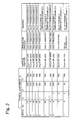
- Fig. 2 is a diagram showing composition ratios of Mn and the like of Fe-Mn alloy powders produced in Examples A to D, Fe-Mn alloy powders in Comparative Examples E and F, an Fe-Mn alloy powder in Example G, and Fe-Mn-Si alloy powders in Comparative Examples H to J.
- the alloy powders in Examples A to D, the Fe-Mn alloy powder in Example G, and the alloy powders in Comparative Examples E and F were produced by a gas atomization process using an inert gas.
- the alloy powder in Comparative Example H was produced by a gas atomization process using an inert gas
- the alloy powder in Comparative Example I was produced by a pulverization process
- the alloy powder in Comparative Example J was produced by a water atomization.
- alloy powders in Examples A to D contents of Mn were 2.5 mass%, 6 mass%, 18 mass% and 28 mass%, respectively.
- the alloy powders in Examples A to D were Fe-Mn alloy powders containing 2-30 mass% of Mn.
- contents of Mn were 1.5 mass% and 40 mass%, respectively.
- the alloy powders produced in Examples A to D and the alloy powders in Comparative Examples E and F were classified through a sieve of 330 mesh, and particle diameters of the Fe-Mn alloy powders were adjusted to 50 ⁇ m or less.
- Example G In the alloy powder in Example G, a content of Mn was 6 mass%.
- the particle diameter of the alloy powder in Example G was 100 ⁇ m or more, which was larger than that of the other alloy powders.
- the alloy powders in Comparative Examples H to J were produced for comparison with the Fe-Mn alloy powders.
- a content of Mn was 6 mass%, which was the same as that of Mn in the alloy powder in Example B.
- each of the alloy powders in Comparative Examples H to J contained 2 mass% of Si.
- the production processes thereof were different from each other as described above, and hence contents of oxygen contained in the alloy powders were different.
- the content of oxygen in the alloy powder in Comparative Example H was 0.06 mass%, and compared with an oxygen content of 0.2 mass% in the alloy powders in Comparative Examples I to J, the alloy powder in Comparative Example H produced by the gas atomization process had the smallest oxygen content.
- the alloy powders in Comparative Examples H to J were classified through a sieve of 330 mesh, and a particle diameter of each alloy powder was adjusted to 50 ⁇ m or less.
- Fig. 3 is a diagram showing material powder mixing ratios and the like of Fe-based sintered alloys in Examples 1 to 4, Fe-based sintered alloys in Comparative Examples 5 to 7, an Fe-based sintered alloy in Example 8, and Fe-based sintered alloys in Comparative Examples 9 to 16.
- a mixing ratio of the alloy powder in Example A was 45 mass%
- a mixing ratio of the alloy powder in Example B was 30 mass%
- a mixing ratio of the alloy powder in Example C was 10 mass%
- a mixing ratio of the alloy powder in Example D was 6 mass%, respectively.
- Mixing ratios of the Fe-Mn alloy powders in the Fe-based sintered alloys in Examples 1 to 4 were all in a range of 5 mass% to 50 mass%.
- mixing ratios of the alloy powder in Comparative Example E were 60 mass% and 99 mass%, respectively.
- a mixing ratio of the alloy powder in Comparative Example F was 2 mass%.
- a mixing ratio of the alloy powder in Comparative Example G was 3 mass%.
- a mixing ratio of the alloy powder in Example B was 30 mass%. Furthermore, in the Fe-based sintered alloy in Comparative Example 12, a mixing ratio of the graphite powder was 0.1 mass%, and in the Fe-based sintered alloy in Comparative Example 13, a mixing ratio of the graphite powder was 2.5 mass%.
- the Fe-based sintered alloy in Comparative Example 14 a mixing ratio of the alloy powder in Example A was 55 mass%, and in the Fe-based sintered alloy in Comparative Example 15, a mixing ratio of the alloy powder in Example D was 3 mass%. In every case of the Fe-based sintered alloys in Comparative Examples 14 and 15, a mixing ratio of the graphite powder was 1 mass%. It is to be noted that the Fe-based sintered alloy in Comparative Example 16 was a conventional Fe-based sintered alloy which was mixed with a Cu powder stipulated in JIS S MF4050.
- material powders of each Fe-based sintered alloy were mixed in a mixing ratio shown in Fig. 3 in the above mixing step (S16).
- 0.8 mass% of zinc stearate was added as a lubricant to the material powders, and the mixing was carried out by use of a V-type mixer.
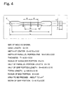
- Fig. 4 is a diagram showing a shape of a compact which was compacted in the compacting step (S18).
- the compact obtained in the compacting step (S18) was sintered in the above sintering step (S20).
- the sintering was carried out at a sintering temperature of 1150°C for a sintering time of 30 minutes in a nitrogen gas atmosphere by use of a sintering furnace.
- tensile tests were carried out at room temperature in accordance with JIS Z 2241.
- a shape of each test piece for the tensile test was the same as shown in Fig. 4.
- a tensile test speed was 0.5 mm/minute in terms of a cross head speed of a tensile tester.
- the Fe-based sintered alloys obtained in Examples 1 to 4 had tensile strengths of 620-650 MPa. It is shown that all the Fe-based sintered alloys were more improved in tensile strength than the conventional Fe-based sintered alloy in Comparative Example 16. Furthermore, the Fe-based sintered alloys in Examples 1 to 4 had higher tensile strengths than the other Fe-based sintered alloys shown in Fig. 3, and particularly in the Fe-based sintered alloys in Examples 1 to 4, higher tensile strengths were obtained than the Fe-based sintered alloys using Fe-Mn-Si alloy powders in Comparative Examples 9 to 11.
- a concentration of Mn at a site formed from the Fe powder was analyzed using electron probe micro-analysis (EPMA).
- EPMA electron probe micro-analysis
- Fig. 5 is a microgram showing a metallic texture of the Fe-based sintered alloy in Example 2.
- an X-ray microanalysis device type: MACHS200, made by Shimadzu Seisakusho Ltd. was used.
- the concentrations of Mn at the site formed from the Fe powder were in a range of 1 mass% to 2 mass%.
- the concentrations of Mn at the site formed from the Fe powder were higher than the other Fe-based sintered alloys shown in Fig. 3, and it is shown that Mn was diffused in large quantities from the Fe-Mn alloy powder into the Fe powder during the sintering.
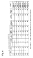
- Fig. 6 is a diagram showing tensile strengths and the like in a case where a plurality of conditions such as compacting conditions and sintering conditions are set in Fe-based sintered alloys in Examples 17 to 25.
- the Fe-based sintered alloys in Examples 17 to 25 were produced by mixing 30 mass% of the alloy powder in Example B, 1 mass% of the graphite powder and the remainder of the Fe powder in mixing ratios, and setting a plurality of conditions of a compacting pressure in the above compacting step (S18) as well as a sintering temperature and a sintering time in the above sintering step (S20).
- the Fe-based sintered alloys in Examples 17 to 19 were produced setting compacting pressures to 300 MPa, 500 MPa and 1500 MPa while a sintering temperature of 1150°C and a sintering time of 30 minutes were fixed.
- the Fe-based sintered alloys in Examples 20 to 22 were produced setting sintering temperatures to 1050°C, 1100°C and 1250°C while a compacting pressure of 800 MPa and a sintering time of 30 minutes were fixed.
- the Fe-based sintered alloys in Examples 23 to 25 were produced setting sintering times to 5 minutes, 10 minutes and 120 minutes while a compacting pressure of 800 MPa and a sintering temperature of 1150°C were fixed.
- the Fe-based sintered alloys in Examples 17 to 25 were carried out in the above test manners.
- the Fe-based sintered alloys having tensile strengths of 600 MPa or more were obtained by compacting under compacting pressures of 500-1500 MPa, and then sintering at sintering temperatures of 1100°C-1250°C for sintering times of 10-120 minutes.
- the Fe-based sintered alloys having tensile strengths of 600 MPa or more had densities of 7.2-7.4 g/cm 3 .
- Fig. 7 is a diagram showing contents of Mn and the like contained in Fe-based sintered alloys in Examples 26 to 31.
- the Fe-based sintered alloys in Examples 26 and 29 were Fe-based sintered alloys including the alloy powder in Example A in mixing ratios of 30 mass% and 15 mass%, respectively.
- the Fe-based sintered alloys in Examples 27 and 30 were Fe-based sintered alloys including the alloy powder in Example C in mixing ratios of 25 mass% and 35 mass%, respectively.
- the Fe-based sintered alloys in Examples 28 and 31 were Fe-based sintered alloys including the alloy powder in Example D in mixing ratios of 15 mass% and 25 mass%, respectively.
- each of the Fe-based sintered alloys in Examples 26 to 31 included the graphite powder in a mixing ratio of 1 mass%.
- Each of the Fe-based sintered alloys in Examples 26 to 31 was produced by mixing material powders in a material powder mixing ratio shown in Fig. 7 in the above mixing step (S16), pressing and compacting the mixed powder at 800 MPa in the above mixing step (S18), and then sintering the resultant compact at a sintering temperature of 1150°C for a sintering time of 30 minutes in the above mixing step (S20).
Landscapes
- Chemical & Material Sciences (AREA)
- Engineering & Computer Science (AREA)
- Materials Engineering (AREA)
- Mechanical Engineering (AREA)
- Metallurgy (AREA)
- Organic Chemistry (AREA)
- Powder Metallurgy (AREA)
Abstract
There is here disclosed an Fe-based sintered alloy produced through a mixing step of mixing an Fe-Mn alloy powder, graphite powder and Fe powder by a mixer (S16), a compacting step of compacting the mixed powder at a predetermined pressure (S18), and a sintering step of sintering the resultant compact in a sintering oven at a predetermined temperature for a predetermined time (S20), the Fe-Mn alloy powder being characterized by containing 2-30 mass% of Mn. In particular, the mixing step (S16) is carried out by mixing 5-50 mass% of the Fe-Mn alloy powder, 0.2-2 mass% of the graphite powder, and the remainder of the Fe powder in the mixer. Consequently, mechanical strength of the Fe-based sintered alloy can be further improved.
Description
- The present invention relates to an Fe-based sintered alloy, and more particularly, it relates to an Fe-based sintered alloy produced through a mixing step of mixing an Fe-Mn alloy powder, graphite powder and Fe powder, a compacting step of compacting the mixed powder, and a sintering step of sintering the resultant compact.
- A powder metallurgical technique has advantages that size control and compacting of a complex shape are easier and a cost is lower compared with parts producing techniques of casting, forging and the like. Therefore, the powder metallurgical technique is widely used. Particularly in sintered structure parts for automobiles, many Fe-based sintered alloys are used.
- Among the Fe-based sintered alloys, Fe-Cu-based sintered alloys each produced by mixing an Fe powder, Cu power and graphite, followed by compacting and sintering, have heretofore been used. Here, the Cu powder is melted at a sintering temperature or less of the Fe powder to promote the sintering with the Fe powder, whereby mechanical strength of the sintered alloy is effectively improved. A sintering temperature of the Fe-Cu-based sintered alloys is usually in a range of 1100°C to 1200°C. The Fe-Cu-based sintered alloys are applied to, for example, clutch hubs, connecting rods and the like for automobiles.
- Furthermore, in the Fe-based sintered alloy, the improvement of the mechanical strength has been made by adding any of various metallic powders and alloy powders. For example, in an Fe-Mn-Si-based sintered alloy produced by mixing an Fe-Mn-Si alloy powder including Mn and Si in place of the Cu powder with the Fe powder and graphite powder, compacting and then sintering the resultant mixture, the mechanical strength has been further improved. The above Fe-Mn-Si-based sintered alloy is principally sintered at 1200°C or more to promote the sintering of the Fe-Mn-Si alloy powder and the Fe powder, because a liquid phase line of the Fe-Mn-Si alloy powder is at substantially 1200°C (e.g., see Non-patent Literature 1).
- Non-patent Literature 1: Zongyin Zhang and another, Fe-Mn-Si master alloy steel by powder metallurgy processing, Sweden, Journal of Alloys and Compounds, 2004, Vol. 363, p. 194-202.
- To lighten the weight of sintered structure parts for automobiles at a low cost, it is necessary to further improve mechanical strength of the parts at a sintering temperature equal to that of an Fe-Cu-based sintered alloy in the above conventional technique. Furthermore, in a case where an Fe-Mn-Si alloy powder is used in place of a Cu powder and sintered at the same sintering temperature as that of the Fe-Cu-based sintered alloy, during the sintering of the Fe-Mn-Si alloy powder and an Fe powder, the dispersion of an element such as Mn between the powders might be disturbed by an oxide film of Si in the alloy powder formed on the surface of the alloy powder. In consequence, the sintering cannot be promoted any more in some cases. Morever, owing to the addition of Si, an intermetallic compound of Fe and Si is formed in the Fe-Mn-Si alloy powder, and hence the alloy power becomes hard. In consequence, the density of a compact decreases, whereby the density of the sintered alloy also decreases, and hence sufficient mechanical strength cannot be obtained in some cases.
- Accordingly, an object of the present invention is to provide an Fe-based sintered alloy having improved mechanical strength produced through a mixing step of mixing an Fe-Mn alloy powder, graphite powder and Fe powder, a compacting step of compacting the mixed powder, and a sintering step of sintering the resultant compact.
- The Fe-based sintered alloy according to the present invention is an Fe-based sintered alloy produced through a mixing step of mixing an Fe-Mn alloy powder, graphite powder and Fe powder, a compacting step of compacting the mixed powder, and a sintering step of sintering the resultant compact, and the Fe-Mn alloy powder is characterized by containing Mn in an amount of 2-30 mass%.
- In the production of the Fe-based sintered alloy according to the present invention, the mixing step is preferably accomplished by mixing 5-50 mass% of Fe-Mn alloy powder, 0.2-2 mass% of the graphite powder and the remainder of the Fe powder.
- As understood from the above, in the production of the Fe-based sintered alloy according to the present invention, the Fe-Mn alloy powder is used in place of the Cu powder, and hence the mechanical strength can be improved at the same sintering temperature as that of the Fe-Cu-based sintered alloy of a conventional technique.
-
- Fig. 1 is a diagram showing production steps of an Fe-based sintered alloy, in an embodiment according to the present invention;
- Fig. 2 is a diagram showing composition ratios of Mn and the like of Fe-Mn alloy powders produced in Examples A to D, Fe-Mn alloy powders in Comparative Examples E and F, an Fe-Mn alloy powder in Example G, and Fe-Mn-Si alloy powders in Comparative Examples H to J, in embodiments according to the present invention;
- Fig. 3 is a diagram showing material powder mixing ratios and the like of Fe-based sintered alloys in Examples 1 to 4, Fe-based sintered alloys in Comparative Examples 5 to 7, an Fe-based sintered alloy in Example 8, and Fe-based sintered alloys in Comparative Examples 9 to 16, in embodiments of the present invention;
- Fig. 4 is a diagram showing a shape of a compact which is compacted in a compacting step, in the embodiment according to the present invention;
- Fig. 5 is a microgram showing a metallic texture of the Fe-based sintered alloy in Example 2, in the embodiment according to the present invention;
- Fig. 6 is a diagram showing tensile strengths and the like' in cases where a plurality of conditions such as compacting conditions and sintering conditions are set in Fe-based sintered alloys in Examples 17 to 25, in the embodiments according to the present invention;
- Fig. 7 is a diagram showing contents of Mn and the like contained in Fe-based sintered alloys in Examples 26 to 31, in the embodiments according to the present invention.
- Embodiments of the present invention will be described in detail with reference to the drawings. Fig. 1 is a diagram showing production steps of an Fe-based sintered alloy. The Fe-based sintered alloy is produced by a step (S10) of producing an Fe-Mn alloy powder containing Mn in an amount of 2-30 mass%, a step (S12) of producing a graphite powder, a step (S14) of producing an Fe powder, a mixing step (S16) of mixing these powders, a compacting step (S18) of compacting the mixed powder, and a sintering step (S20) of sintering the resultant compact.
- First, the step (S10) of producing the Fe-Mn alloy powder will be described.
- The Fe-Mn alloy powder is produced by a gas atomization process so as to obtain the powder having less oxide contents. Needless to say, the production of the Fe-Mn alloy powder may be made by use of a mechanical production process such as pulverization, a production process by electrolysis, a chemical production process by reduction of an oxide or thermal decomposition, or a water atomization process for producing the powder from a molten metal by jet.
- Here, Mn contained in the Fe-Mn alloy powder plays a role of promoting the sintering between the Fe-Mn alloy powder and the Fe powder by the diffusion of Mn during the sintering. The reason why the content of Mn in the Fe-Mn alloy powder is 2 mass% or more is that if the content of Mn is less than 2 mass%, the diffusion promotion of Mn is poor. The reason why the content of Mn is 30 mass% or less is that if the content of Mn is more than 30 mass%, compactibility of the powder in the compacting step (S18) deteriorates and mechanical strength of a sintered alloy cannot be improved. Therefore, the Fe-Mn alloy powder containing Mn in an amount of 2-30 mass% is used.
- As the Fe-Mn alloy powder, there is used a powder passed through a sieve having a predetermined mesh to regulate particle diameters. If the Fe-Mn alloy powder has large particle diameters, a filling ratio of the powder is low during the compacting of the Fe-Mn alloy powder by the compacting step (S18), which has an influence on the mechanical strength of the sintered alloy. The Fe-Mn alloy powder having particle diameters of, for example, 5-50 µm is used. Needless to say, the particle diameters of the Fe-Mn alloy powder may be 5-200 µm or 5-100 µm, and these particle diameters are not particularly limited.
- Next, the production step (S12, S14) of producing the graphite powder and Fe powder will be described. The graphite powder is produced by a mechanical production process such as pulverization and then it is used. Needless to say, the graphite powder may be produced by a chemical production process such as thermal decomposition and then it may be used. Furthermore, the Fe powder is produced by a water atomization process and then it is used. Needless to say, it may be produced by a mechanical production process such as pulverization, a gas atomization process, or a reduction process.
- The mixing step (S16) of mixing the Fe-Mn alloy powder, the graphite powder and the Fe powder will be described. A mixed powder is obtained by mixing 5-50 mass% of the Fe-Mn alloy powder, 0.2-2 mass% of the graphite powder and the remainder of the Fe powder, and the resultant mixed powder is then used.
- The Fe-Mn alloy powder is added to promote the diffusion of elements between the powders during the sintering. The reason why an amount of the Fe-Mn alloy powder is 5 mass% or more is that if a mixing ratio of the Fe-Mn alloy powder is less than 5 mass%, the promotion of the Mn diffusion is poor, with the result that the mechanical strength of the sintered alloy is not sufficiently improved. The reason why a mixing ratio of the Fe-Mn alloy powder is 50 mass% or less is that if the mixing ratio of the Fe-Mn alloy powder is more than 50 mass%, the compactibility of the powder in the compacting step (S18) deteriorates and the mechanical strength of the sintered alloy cannot be improved. In consequence, the Fe-Mn alloy powder is used in a mixing ratio of 5-50 mass%.
- The graphite powder is added to reinforce the Fe-based sintered alloy. The reason why a mixing ratio of the graphite powder is 0.2 mass% or more is that if it is less than 0.2 mass%, a ferrite increases and hence hardness of the sintered alloy deteriorates, which leads to the deterioration of the mechanical strength. The reason why a mixing ratio of the graphite powder is 2 mass% or less is that if it is more than 2 mass%, a cementite increases and hence toughness of the sintered alloy deteriorates. Therefore, the graphite powder is used in a mixing ratio of 0.2-2 mass%.
- In the mixing step (S16), the Fe-Mn alloy powder, graphite powder and Fe powder are sufficiently dried, and these powers are then put into a mixer, followed by mixing. It is to be noted that a lubricant may be added thereto for the purpose of decreasing friction between a mold and the mixed powder in the subsequent compacting step (S18). As the lubricant, a stearate such as zinc stearate is used. Needless to say, the stearate is not limited, and another type of lubricant may be used. As the mixer for mixing these powders, a V-type mixer may be used, but this is not particularly limited.
- Next, the compacting step (S18) of compacting the mixed powder of the Fe-Mn alloy powder, graphite powder and Fe powder will be described. To impart a predetermined shape to the mixed powder, for example, a mold is packed with the mixed powder. The mold packed with the mixed powder is pressed in a monaxial direction to compact it. Needless to say, the press direction is limited to the monaxial direction, and the mixed powder may be pressed in an isostatic direction. As a pressure to compact the mixed powder, 800 Mpa is used. Needless to say, the pressure may be in a range of 500 MPa to 1500 MPa, but these pressures are not particularly limited.
- As a compacting device, a pressing machine or the like is used in a case where the mixed powder is pressed in the monaxial direction. It is to be noted that in a case where the mixed powder is pressed in the isostatic direction, there is used a CIP (cold isostatic pressing) device, an HIP (hot isostatic pressing) device, or the like. Needless to say, any compacting machine may be used as long as it can apply the above pressure, and hence the aforesaid devices are not limited. The mixed powder is compacted at room temperature, but this temperature is not limited, and the mixed powder may be compacted while being heated.
- Next, the sintering step (S20) of sintering the resultant compact will be described. The compact obtained by compacting the mixed powder is released from the mold, and then sintered in a sintering furnace. For an atmosphere in the sintering furnace, an inert gas, for example, an argon gas or a helium gas is used. Needless to say, the sintering atmosphere is not particularly limited, and a decomposed gas of ammonia, hydrogen, or a nitrogen gas may be used. A vacuum atmosphere may also be used.
- As a sintering temperature, for example, 1150°C is used. Needless to say, the sintering temperature may be in a range of 1100°C to 1250°C. These sintering temperatures are not particularly limited. As a sintering time, for example, a time of 30 minutes is used. Needless to say, the sintering time may be in a range of 10 minutes to 120 minutes, and these times are not particularly limited. As the sintering furnace used in the sintering step (S20), a general sintering furnace for use in powder metallurgy can be used. The sintering furnace is not particularly limited, so long as it can adjust the above sintering atmosphere, sintering temperature and sintering time.
- As will be understood from the above, according to the Fe-based sintered alloy, Mn in the Fe-Mn alloy powder diffuses in the Fe powder to promote the sintering, so that the mechanical strength of the Fe-based sintered alloy can be further improved. Accordingly, sintered structure parts for automobiles can be lightened at a low cost.
- Fig. 2 is a diagram showing composition ratios of Mn and the like of Fe-Mn alloy powders produced in Examples A to D, Fe-Mn alloy powders in Comparative Examples E and F, an Fe-Mn alloy powder in Example G, and Fe-Mn-Si alloy powders in Comparative Examples H to J. The alloy powders in Examples A to D, the Fe-Mn alloy powder in Example G, and the alloy powders in Comparative Examples E and F were produced by a gas atomization process using an inert gas. Furthermore, the alloy powder in Comparative Example H was produced by a gas atomization process using an inert gas, the alloy powder in Comparative Example I was produced by a pulverization process, and the alloy powder in Comparative Example J was produced by a water atomization.
- In the alloy powders in Examples A to D, contents of Mn were 2.5 mass%, 6 mass%, 18 mass% and 28 mass%, respectively. The alloy powders in Examples A to D were Fe-Mn alloy powders containing 2-30 mass% of Mn. In the alloy powders in Comparative Examples E and F, contents of Mn were 1.5 mass% and 40 mass%, respectively. The alloy powders produced in Examples A to D and the alloy powders in Comparative Examples E and F were classified through a sieve of 330 mesh, and particle diameters of the Fe-Mn alloy powders were adjusted to 50 µm or less.
- In the alloy powder in Example G, a content of Mn was 6 mass%. The particle diameter of the alloy powder in Example G was 100 µm or more, which was larger than that of the other alloy powders.
- The alloy powders in Comparative Examples H to J were produced for comparison with the Fe-Mn alloy powders. In each of the alloy powders in Comparative Examples H to J, a content of Mn was 6 mass%, which was the same as that of Mn in the alloy powder in Example B. Furthermore, each of the alloy powders in Comparative Examples H to J contained 2 mass% of Si. For the alloy powders in Comparative Examples H to J, the production processes thereof were different from each other as described above, and hence contents of oxygen contained in the alloy powders were different. The content of oxygen in the alloy powder in Comparative Example H was 0.06 mass%, and compared with an oxygen content of 0.2 mass% in the alloy powders in Comparative Examples I to J, the alloy powder in Comparative Example H produced by the gas atomization process had the smallest oxygen content. The alloy powders in Comparative Examples H to J were classified through a sieve of 330 mesh, and a particle diameter of each alloy powder was adjusted to 50 µm or less.
- Fig. 3 is a diagram showing material powder mixing ratios and the like of Fe-based sintered alloys in Examples 1 to 4, Fe-based sintered alloys in Comparative Examples 5 to 7, an Fe-based sintered alloy in Example 8, and Fe-based sintered alloys in Comparative Examples 9 to 16.
- In the Fe-based sintered alloys in Examples 1 to 4, a mixing ratio of the alloy powder in Example A was 45 mass%, a mixing ratio of the alloy powder in Example B was 30 mass%, a mixing ratio of the alloy powder in Example C was 10 mass%, and a mixing ratio of the alloy powder in Example D was 6 mass%, respectively. Mixing ratios of the Fe-Mn alloy powders in the Fe-based sintered alloys in Examples 1 to 4 were all in a range of 5 mass% to 50 mass%.
- In the Fe-based sintered alloys in Comparative Examples 5 and 6, mixing ratios of the alloy powder in Comparative Example E were 60 mass% and 99 mass%, respectively. In the Fe-based sintered alloy in Comparative Example 7, a mixing ratio of the alloy powder in Comparative Example F was 2 mass%. In the Fe-based sintered alloy in Example 8, a mixing ratio of the alloy powder in Comparative Example G was 3 mass%.
- Furthermore, in every case of the Fe-based sintered alloys in Examples 1 to 4, the Fe-based sintered alloys in Comparative Examples 5 to 7, and the Fe-based sintered alloy in Example 8, a mixing ratio of the graphite powder was 1 mass%, which was in a range of 0.2 mass% to 2 mass%.
- In each of the Fe-based sintered alloys in Comparative Examples 9 to 11, a mixing ratio of the alloy powders in Comparative Examples H to J was 30 mass%, and a mixing ratio of the graphite powder was 1 mass%.
- In each of the Fe-based sintered alloys in Comparative Examples 12 to 13, a mixing ratio of the alloy powder in Example B was 30 mass%. Furthermore, in the Fe-based sintered alloy in Comparative Example 12, a mixing ratio of the graphite powder was 0.1 mass%, and in the Fe-based sintered alloy in Comparative Example 13, a mixing ratio of the graphite powder was 2.5 mass%.
- In the Fe-based sintered alloy in Comparative Example 14, a mixing ratio of the alloy powder in Example A was 55 mass%, and in the Fe-based sintered alloy in Comparative Example 15, a mixing ratio of the alloy powder in Example D was 3 mass%. In every case of the Fe-based sintered alloys in Comparative Examples 14 and 15, a mixing ratio of the graphite powder was 1 mass%. It is to be noted that the Fe-based sintered alloy in Comparative Example 16 was a conventional Fe-based sintered alloy which was mixed with a Cu powder stipulated in JIS S MF4050.
- For the production of the Fe-based sintered alloy shown in Fig. 3, material powders of each Fe-based sintered alloy were mixed in a mixing ratio shown in Fig. 3 in the above mixing step (S16). Prior to the mixing, 0.8 mass% of zinc stearate was added as a lubricant to the material powders, and the mixing was carried out by use of a V-type mixer.
- The mixed powder obtained by the mixing in the mixing step (S16) was compacted in the above compacting step (S18). The compacting was carried out by putting the mixed powder into the mold, and then pressing it at 800 MPa in a monaxial direction by a pressing machine. Fig. 4 is a diagram showing a shape of a compact which was compacted in the compacting step (S18).
- The compact obtained in the compacting step (S18) was sintered in the above sintering step (S20). The sintering was carried out at a sintering temperature of 1150°C for a sintering time of 30 minutes in a nitrogen gas atmosphere by use of a sintering furnace. For the Fe-based sintered alloys shown in Fig. 3, tensile tests were carried out at room temperature in accordance with JIS Z 2241. A shape of each test piece for the tensile test was the same as shown in Fig. 4. Furthermore, a tensile test speed was 0.5 mm/minute in terms of a cross head speed of a tensile tester.
- According to the results of the tensile tests, as shown in Fig. 3, the Fe-based sintered alloys obtained in Examples 1 to 4 had tensile strengths of 620-650 MPa. It is shown that all the Fe-based sintered alloys were more improved in tensile strength than the conventional Fe-based sintered alloy in Comparative Example 16. Furthermore, the Fe-based sintered alloys in Examples 1 to 4 had higher tensile strengths than the other Fe-based sintered alloys shown in Fig. 3, and particularly in the Fe-based sintered alloys in Examples 1 to 4, higher tensile strengths were obtained than the Fe-based sintered alloys using Fe-Mn-Si alloy powders in Comparative Examples 9 to 11.
- For the Fe-based sintered alloys shown in Fig. 3, density measuring tests were carried out in accordance with JIS Z 2501. The shape of a test piece for each density measuring test was the same as shown in Fig. 4. According to the results of the density measuring tests, as shown in Fig. 3, the Fe-based sintered alloys obtained in Examples 1 to 4 had densities of 7.15-7.25 g/cm3. As will be understood from the above, in the Fe-based sintered alloys in Examples 1 to 4, higher densities were obtained than the other Fe-based sintered alloys shown in Fig. 3.
- To examine a diffusion state of Mn from the Fe-Mn alloy powder into the Fe powder, a concentration of Mn at a site formed from the Fe powder was analyzed using electron probe micro-analysis (EPMA). As an example, Fig. 5 is a microgram showing a metallic texture of the Fe-based sintered alloy in Example 2. As an analyzer, an X-ray microanalysis device (type: MACHS200, made by Shimadzu Seisakusho Ltd.) was used. In the Fe-based sintered alloys in Examples 1 to 4, the concentrations of Mn at the site formed from the Fe powder were in a range of 1 mass% to 2 mass%. In the Fe-based sintered alloys in Examples 1 to 4, the concentrations of Mn at the site formed from the Fe powder were higher than the other Fe-based sintered alloys shown in Fig. 3, and it is shown that Mn was diffused in large quantities from the Fe-Mn alloy powder into the Fe powder during the sintering.
- Fig. 6 is a diagram showing tensile strengths and the like in a case where a plurality of conditions such as compacting conditions and sintering conditions are set in Fe-based sintered alloys in Examples 17 to 25. The Fe-based sintered alloys in Examples 17 to 25 were produced by mixing 30 mass% of the alloy powder in Example B, 1 mass% of the graphite powder and the remainder of the Fe powder in mixing ratios, and setting a plurality of conditions of a compacting pressure in the above compacting step (S18) as well as a sintering temperature and a sintering time in the above sintering step (S20).
- The Fe-based sintered alloys in Examples 17 to 19 were produced setting compacting pressures to 300 MPa, 500 MPa and 1500 MPa while a sintering temperature of 1150°C and a sintering time of 30 minutes were fixed. The Fe-based sintered alloys in Examples 20 to 22 were produced setting sintering temperatures to 1050°C, 1100°C and 1250°C while a compacting pressure of 800 MPa and a sintering time of 30 minutes were fixed. The Fe-based sintered alloys in Examples 23 to 25 were produced setting sintering times to 5 minutes, 10 minutes and 120 minutes while a compacting pressure of 800 MPa and a sintering temperature of 1150°C were fixed.
- For the Fe-based sintered alloys in Examples 17 to 25, tensile tests and density measuring tests were carried out in the above test manners. As shown in Fig. 6, the Fe-based sintered alloys having tensile strengths of 600 MPa or more were obtained by compacting under compacting pressures of 500-1500 MPa, and then sintering at sintering temperatures of 1100°C-1250°C for sintering times of 10-120 minutes. Furthermore, the Fe-based sintered alloys having tensile strengths of 600 MPa or more had densities of 7.2-7.4 g/cm3.
- Fig. 7 is a diagram showing contents of Mn and the like contained in Fe-based sintered alloys in Examples 26 to 31. The Fe-based sintered alloys in Examples 26 and 29 were Fe-based sintered alloys including the alloy powder in Example A in mixing ratios of 30 mass% and 15 mass%, respectively. The Fe-based sintered alloys in Examples 27 and 30 were Fe-based sintered alloys including the alloy powder in Example C in mixing ratios of 25 mass% and 35 mass%, respectively. The Fe-based sintered alloys in Examples 28 and 31 were Fe-based sintered alloys including the alloy powder in Example D in mixing ratios of 15 mass% and 25 mass%, respectively. Furthermore, each of the Fe-based sintered alloys in Examples 26 to 31 included the graphite powder in a mixing ratio of 1 mass%.
- Each of the Fe-based sintered alloys in Examples 26 to 31 was produced by mixing material powders in a material powder mixing ratio shown in Fig. 7 in the above mixing step (S16), pressing and compacting the mixed powder at 800 MPa in the above mixing step (S18), and then sintering the resultant compact at a sintering temperature of 1150°C for a sintering time of 30 minutes in the above mixing step (S20).
- For the Fe-based sintered alloys in Examples 17 and 25, tensile tests, density measuring tests and concentration analyses of Mn at a site formed from the Fe powder were carried out in the above manners. A content of Mn in each Fe-based sintered alloy was measured and calculated using a high-frequency plasma atomic emission spectrometer (ICP).
- As shown in Fig. 7, in the Fe-based sintered alloys in Examples 26 to 28, contents of Mn were 0.8 mass%, 4.5 mass% and 4.2 mass%, respectively. In the Fe-based sintered alloys in Examples 29 to 31, contents of Mn were 0.4 mass%, 6.3 mass% and 7.0 mass%, respectively. In every case of the Fe-based sintered alloys in Examples 26 to 28, tensile strengths were 600 MPa or more. Therefore, the content of Mn in the Fe-based sintered alloy which can obtain a tensile strength of 600 MPa or more was 0.5-5 mass%.
Claims (2)
- An Fe-based sintered alloy produced through
a mixing step of mixing an Fe-Mn alloy powder, graphite powder and Fe powder,
a compacting step of compacting the mixed powder, and
a sintering step of sintering the resultant compact,
the Fe-Mn alloy powder being characterized by containing 2-30 mass% of Mn. - The Fe-based sintered alloy according to claim 1, wherein the mixing step is characterized by mixing 5-50 mass% of the Fe-Mn alloy powder, 0.2-2 mass% of the graphite powder, and the remainder of the Fe powder.
Applications Claiming Priority (2)
| Application Number | Priority Date | Filing Date | Title |
|---|---|---|---|
| JP2005125202A JP2006299364A (en) | 2005-04-22 | 2005-04-22 | Fe-based sintered alloy |
| PCT/JP2006/305907 WO2006114960A1 (en) | 2005-04-22 | 2006-03-17 | Iron-based sintered alloy |
Publications (1)
| Publication Number | Publication Date |
|---|---|
| EP1873269A1 true EP1873269A1 (en) | 2008-01-02 |
Family
ID=37214591
Family Applications (1)
| Application Number | Title | Priority Date | Filing Date |
|---|---|---|---|
| EP06729855A Withdrawn EP1873269A1 (en) | 2005-04-22 | 2006-03-17 | Iron-based sintered alloy |
Country Status (6)
| Country | Link |
|---|---|
| US (1) | US20090064819A1 (en) |
| EP (1) | EP1873269A1 (en) |
| JP (1) | JP2006299364A (en) |
| KR (1) | KR20070112875A (en) |
| CN (1) | CN101163809A (en) |
| WO (1) | WO2006114960A1 (en) |
Families Citing this family (4)
| Publication number | Priority date | Publication date | Assignee | Title |
|---|---|---|---|---|
| JP5308123B2 (en) * | 2008-11-10 | 2013-10-09 | 株式会社神戸製鋼所 | High-strength composition iron powder and sintered parts using it |
| CN106282742A (en) * | 2015-05-26 | 2017-01-04 | 东南大学 | A kind of preparation method of high efficiency bulk alloy cementite |
| JP6352959B2 (en) * | 2016-02-04 | 2018-07-04 | トヨタ自動車株式会社 | Method for producing wear-resistant iron-based sintered alloy, compact for sintered alloy, and wear-resistant iron-based sintered alloy |
| JP6431012B2 (en) * | 2016-09-16 | 2018-11-28 | トヨタ自動車株式会社 | Method for producing wear-resistant iron-based sintered alloy and wear-resistant iron-based sintered alloy |
Family Cites Families (5)
| Publication number | Priority date | Publication date | Assignee | Title |
|---|---|---|---|---|
| US2489839A (en) * | 1946-04-30 | 1949-11-29 | Isthmian Metals Inc | Process for carburizing compacted iron articles |
| US2903354A (en) * | 1956-10-16 | 1959-09-08 | Republic Steel Corp | Process for improving parts formed by powder metallurgy by addition of spiegeleisen to metal powders |
| US5834640A (en) * | 1994-01-14 | 1998-11-10 | Stackpole Limited | Powder metal alloy process |
| SE9404110D0 (en) * | 1994-11-25 | 1994-11-25 | Hoeganaes Ab | Manganese containing materials having high tensile strength |
| US5881354A (en) * | 1996-05-03 | 1999-03-09 | Stackpole Limited | Sintered hi-density process with forming |
-
2005
- 2005-04-22 JP JP2005125202A patent/JP2006299364A/en not_active Withdrawn
-
2006
- 2006-03-17 EP EP06729855A patent/EP1873269A1/en not_active Withdrawn
- 2006-03-17 WO PCT/JP2006/305907 patent/WO2006114960A1/en not_active Ceased
- 2006-03-17 KR KR1020077024043A patent/KR20070112875A/en not_active Ceased
- 2006-03-17 US US11/918,982 patent/US20090064819A1/en not_active Abandoned
- 2006-03-17 CN CNA2006800134851A patent/CN101163809A/en active Pending
Non-Patent Citations (1)
| Title |
|---|
| See references of WO2006114960A1 * |
Also Published As
| Publication number | Publication date |
|---|---|
| US20090064819A1 (en) | 2009-03-12 |
| CN101163809A (en) | 2008-04-16 |
| WO2006114960A1 (en) | 2006-11-02 |
| JP2006299364A (en) | 2006-11-02 |
| KR20070112875A (en) | 2007-11-27 |
Similar Documents
| Publication | Publication Date | Title |
|---|---|---|
| CA2911031C (en) | Alloy steel powder for powder metallurgy and method of producing iron-based sintered body | |
| EP0457418A1 (en) | An optimized double press-double sinter powder metallurgy method | |
| CA2922018C (en) | Alloy steel powder for powder metallurgy and method of producing iron-based sintered body | |
| KR20170080668A (en) | Alloy steel powder for powder metallurgy, and sintered body | |
| US9359662B2 (en) | Iron-carbon master alloy | |
| Danninger et al. | Dissolution of different graphite grades during sintering of PM steels | |
| EP0038558B1 (en) | Process for producing sintered ferrous alloys | |
| JP3177482B2 (en) | Low alloy steel powder for sinter hardening | |
| US7384446B2 (en) | Mixed powder for powder metallurgy | |
| JP3273789B2 (en) | Iron powder and mixed powder for powder metallurgy and method for producing iron powder | |
| US5443787A (en) | Method for preparing iron system soft magnetic sintered body | |
| EP1873269A1 (en) | Iron-based sintered alloy | |
| JP6690781B2 (en) | Alloy steel powder | |
| US20170361378A1 (en) | Compacting of gas atomized metal powder to a part | |
| EP1282478B1 (en) | A method for sintering a carbon steel part using a hydrocolloid binder as carbon source. | |
| CN114728331B (en) | Alloy steel powder for powder metallurgy, iron-based mixed powder and sintered body for powder metallurgy | |
| Lozada et al. | Controlled densification of boron-containing stainless steels | |
| US11590571B2 (en) | Method for producing a sintered component | |
| EP3950174A1 (en) | Iron-based mixed powder for powder metallurgy, and iron-base sintered body | |
| Ramabulana | Sinterability studies of high carbon steel powders containing nickel, molybdenum, cobalt and manganese | |
| Geykhman et al. | Structurally unstable pseudoalloys powder nickel-molybdenum steel-copper | |
| Wendel | Characteristics and Sintering of Fine Water-atomized and Carbonyl Iron Powder | |
| Cias et al. | PM Low Alloy Steels 1: Properties of Sintered Manganese Steels Compacted from Sponge and Water Atomised Ferrous Powders | |
| Unami et al. | Hybrid Type Ni-Mo-Cu Alloyed Steel Powder Suitable for Sinter-Hardening | |
| Danninger et al. | Sintered Steels-Microstructure: Sintered Steels Prealloyed with Manganese-Chances and Risks |
Legal Events
| Date | Code | Title | Description |
|---|---|---|---|
| PUAI | Public reference made under article 153(3) epc to a published international application that has entered the european phase |
Free format text: ORIGINAL CODE: 0009012 |
|
| 17P | Request for examination filed |
Effective date: 20071004 |
|
| AK | Designated contracting states |
Kind code of ref document: A1 Designated state(s): DE FR GB |
|
| DAX | Request for extension of the european patent (deleted) | ||
| RBV | Designated contracting states (corrected) |
Designated state(s): DE FR GB |
|
| STAA | Information on the status of an ep patent application or granted ep patent |
Free format text: STATUS: THE APPLICATION HAS BEEN WITHDRAWN |
|
| 18W | Application withdrawn |
Effective date: 20090409 |