EP1873051A1 - Ship - Google Patents
Ship Download PDFInfo
- Publication number
- EP1873051A1 EP1873051A1 EP06116487A EP06116487A EP1873051A1 EP 1873051 A1 EP1873051 A1 EP 1873051A1 EP 06116487 A EP06116487 A EP 06116487A EP 06116487 A EP06116487 A EP 06116487A EP 1873051 A1 EP1873051 A1 EP 1873051A1
- Authority
- EP
- European Patent Office
- Prior art keywords
- hull
- ship
- ship according
- fin
- horizontal
- Prior art date
- Legal status (The legal status is an assumption and is not a legal conclusion. Google has not performed a legal analysis and makes no representation as to the accuracy of the status listed.)
- Withdrawn
Links
- XLYOFNOQVPJJNP-UHFFFAOYSA-N water Substances O XLYOFNOQVPJJNP-UHFFFAOYSA-N 0.000 claims description 17
- 230000033001 locomotion Effects 0.000 claims description 16
- 230000001419 dependent effect Effects 0.000 claims description 6
- 238000005096 rolling process Methods 0.000 description 4
- 230000000087 stabilizing effect Effects 0.000 description 4
- 238000005273 aeration Methods 0.000 description 2
- 230000000368 destabilizing effect Effects 0.000 description 2
- 230000000694 effects Effects 0.000 description 1
- 239000011888 foil Substances 0.000 description 1
- 239000000463 material Substances 0.000 description 1
- 238000009423 ventilation Methods 0.000 description 1
Images

Classifications
-
- B—PERFORMING OPERATIONS; TRANSPORTING
- B63—SHIPS OR OTHER WATERBORNE VESSELS; RELATED EQUIPMENT
- B63B—SHIPS OR OTHER WATERBORNE VESSELS; EQUIPMENT FOR SHIPPING
- B63B1/00—Hydrodynamic or hydrostatic features of hulls or of hydrofoils
- B63B1/02—Hydrodynamic or hydrostatic features of hulls or of hydrofoils deriving lift mainly from water displacement
- B63B1/04—Hydrodynamic or hydrostatic features of hulls or of hydrofoils deriving lift mainly from water displacement with single hull
- B63B1/06—Shape of fore part
-
- B—PERFORMING OPERATIONS; TRANSPORTING
- B63—SHIPS OR OTHER WATERBORNE VESSELS; RELATED EQUIPMENT
- B63B—SHIPS OR OTHER WATERBORNE VESSELS; EQUIPMENT FOR SHIPPING
- B63B1/00—Hydrodynamic or hydrostatic features of hulls or of hydrofoils
- B63B1/02—Hydrodynamic or hydrostatic features of hulls or of hydrofoils deriving lift mainly from water displacement
- B63B1/04—Hydrodynamic or hydrostatic features of hulls or of hydrofoils deriving lift mainly from water displacement with single hull
-
- B—PERFORMING OPERATIONS; TRANSPORTING
- B63—SHIPS OR OTHER WATERBORNE VESSELS; RELATED EQUIPMENT
- B63B—SHIPS OR OTHER WATERBORNE VESSELS; EQUIPMENT FOR SHIPPING
- B63B39/00—Equipment to decrease pitch, roll, or like unwanted vessel movements; Apparatus for indicating vessel attitude
- B63B39/06—Equipment to decrease pitch, roll, or like unwanted vessel movements; Apparatus for indicating vessel attitude to decrease vessel movements by using foils acting on ambient water
-
- B—PERFORMING OPERATIONS; TRANSPORTING
- B63—SHIPS OR OTHER WATERBORNE VESSELS; RELATED EQUIPMENT
- B63H—MARINE PROPULSION OR STEERING
- B63H1/00—Propulsive elements directly acting on water
-
- B—PERFORMING OPERATIONS; TRANSPORTING
- B63—SHIPS OR OTHER WATERBORNE VESSELS; RELATED EQUIPMENT
- B63H—MARINE PROPULSION OR STEERING
- B63H1/00—Propulsive elements directly acting on water
- B63H1/02—Propulsive elements directly acting on water of rotary type
- B63H1/12—Propulsive elements directly acting on water of rotary type with rotation axis substantially in propulsive direction
- B63H1/14—Propellers
-
- B—PERFORMING OPERATIONS; TRANSPORTING
- B63—SHIPS OR OTHER WATERBORNE VESSELS; RELATED EQUIPMENT
- B63B—SHIPS OR OTHER WATERBORNE VESSELS; EQUIPMENT FOR SHIPPING
- B63B1/00—Hydrodynamic or hydrostatic features of hulls or of hydrofoils
- B63B1/32—Other means for varying the inherent hydrodynamic characteristics of hulls
-
- B—PERFORMING OPERATIONS; TRANSPORTING
- B63—SHIPS OR OTHER WATERBORNE VESSELS; RELATED EQUIPMENT
- B63B—SHIPS OR OTHER WATERBORNE VESSELS; EQUIPMENT FOR SHIPPING
- B63B1/00—Hydrodynamic or hydrostatic features of hulls or of hydrofoils
- B63B1/02—Hydrodynamic or hydrostatic features of hulls or of hydrofoils deriving lift mainly from water displacement
- B63B1/04—Hydrodynamic or hydrostatic features of hulls or of hydrofoils deriving lift mainly from water displacement with single hull
- B63B1/06—Shape of fore part
- B63B2001/066—Substantially vertical stems
-
- Y—GENERAL TAGGING OF NEW TECHNOLOGICAL DEVELOPMENTS; GENERAL TAGGING OF CROSS-SECTIONAL TECHNOLOGIES SPANNING OVER SEVERAL SECTIONS OF THE IPC; TECHNICAL SUBJECTS COVERED BY FORMER USPC CROSS-REFERENCE ART COLLECTIONS [XRACs] AND DIGESTS
- Y02—TECHNOLOGIES OR APPLICATIONS FOR MITIGATION OR ADAPTATION AGAINST CLIMATE CHANGE
- Y02T—CLIMATE CHANGE MITIGATION TECHNOLOGIES RELATED TO TRANSPORTATION
- Y02T70/00—Maritime or waterways transport
- Y02T70/10—Measures concerning design or construction of watercraft hulls
Definitions
- the invention concerns a ship in accordance with the preamble of claim 1.
- a ship is known from the publication Keuning, J.A.; Toxopeus, S.; Pinkster, J.; The effect of bow-shape on the seakeeping performance of a fast monohull; Proceedings of FAST 2001 conference, September 2001; page 197-206; ISBN 0 903055 70 8 , publisher The Royal Institute of Naval Architects.
- the ship according to the invention is described as the AXE BOW design.
- the described disadvantage of the known design is that due to its deep bow and flat aft ship the course stability is insufficient.
- the proposed solution for this is to apply a center skeg or cutwater in the stern region.
- the ship is according to claim 2.
- the fins By designing the fins in this way they increase the flow resistance of the ship only slightly and the more or less vertical front edge makes them very effective.
- the ship is according to claim 3. In this way it is easy to obtain minimal flare in the bow sections so that the displaced volume in waves increases only more or less linearly with the draught and so leads to better ship behavior in waves.
- the ship is according to claim 4.
- This fillet radius makes it possible to reduce the length of the ship and so reducing the wetted surface and the flow resistance without disadvantageously influencing the ships behavior in waves.
- the ship is according to claim 5. This improves the ships behavior in heavy seas as the added resistance in waves is reduced.
- the ship is according to claim 6. In this way the ship can be brought in a speed dependent trim position independent of the load or mass distribution in the ship, thereby reducing drag and improving propulsion efficiency.
- the ship is according to claim 7.
- the adjustable upwards or downwards directed force is obtained independent from the ships speed.
- the ship is according to claim 8.
- the ship is according to claim 9.
- the adjustable upwards or downwards directed force is obtained in efficient way.
- the ship is according to claim 10.
- the combination of the stationary fins with the horizontal fin makes a compact design possible whereby when locating the horizontal fin at sufficient depth of the stationary fin aeration of the horizontal fin is prevented.
- the ship is according to claim 11.
- the upwards or downwards directed forces can be adjusted in an easy way to varying circumstances such as forward speed, incoming waves and possibly also the dynamic movements of the ship.
- the ship is according to claim 12. In this way it is possible to generate with the upwards or downwards directed forces a torque in longitudinal direction of the hull which torque can minimize the rolling movements of the hull.
- the ship is according to claim 13. In this way the upwards and downwards directed forces can dynamically be adjusted dependent on the position and movements of the ship in the water.
- the ship is according to claim 14. In this way the hull is automatically held in the optimal attitude with the lowest resistance so improving the efficiency of the ship.
- the ship is according to claim 15. In this way the pitch, heave and/or roll motion are reduced in an easy way.
- Figure 1 shows a ship 1 which is designed in accordance with the body plan according to figure 2.
- the ship 1 is designed for high speeds and has a single long and slender hull with sides 19, whereby the length of the hull is at least five times the beam and for longer ships as much as seven to eight times the beam. In shorter ships the beam is relatively larger as the hull must include the propulsion means and a wider beam ensures that there remains sufficient stability.
- the ship 1 has one or more propellers 8 and one or more rudders 9.
- the lay out on deck is as usual for instance with a wheel house 2.
- the hull of the ship 1 has a special design, in more detail the design is such that a reduction of the Froude Kriloff forces in particular in the foreship is achieved by minimizing the change in momentaneous submerged volume of the hull whilst it makes larger relative motions relative to the water level due to waves or the ships motions.
- a further measure in the design is to reduce the change in waterline beam of the sections in particular in the foreship whilst it makes the foresaid larger relative motions. This implies there is a minimal flare in the bow sections and a bow 3 has a more or less vertical line or extends less than 30 degrees forward.
- the amount of increased shear in the foreship, shown in figure 2 as deck line 15, is dependent on ship size, speed and wave climate involved.
- a downwards sloping centre line 5 towards the foreship prevents the sections there to leave and re-enter the water whilst the ship is performing larger relative motions.
- the centre line 5 is at it lowest near the bow 3 near point 16 which indicates the maximum draught relative to a waterline 17.
- the amount of negative slope in the bottom 21 is dependent on ship size, speed and wave climate involved.
- the deadrise angle of the sections from bow to stern is carefully determined in order to minimize exciting forces and yet maintain sufficient hydrodynamic lift with minimal resistance.
- the shape of the hull is such that the hull is long and slender, there is no flare in the bow sections and the sides 19 at the bow sections are almost vertical. Near the bow 3 the sides 19 make an angle ⁇ seen in a horizontal plane which is smaller than 40 degrees. There is an increased sheer forward and down sloping centreline forward and the entry of the waterlines 20 are rounded. In order to reduce the wetted surface the bow 3 is rounded with a radius R of at least 0,1m. Depending on the beam of the ship the radius can be at least 1% of the beam.
- the hull itself generates destabilizing yaw and sway forces and moments which may lead to these instabilities.
- the fins 6 preferably have airfoil type section shapes and have reasonable aspects ratios to generate adequate lift to counteract the destabilizing effects in yaw and sway of the hull. They are designed to optimize the yaw stability in particular at the cost of minimal increase in resistance.
- the fins 6 are located away from the center line 5 and preferably near the sides 19 so that they are away from the disturbed area in the water which is the result of the maximum draught 16 of the bow 3 which is much deeper in the water than an aft ship 10.
- the restoring moment of the hull in pitch is relatively small when compared to similar craft. To a lesser extend this is also true for the restoring force in heave.
- the heave motion but in particular the pitch motion may be very effectively reduced by the application of one or more activated horizontal fins 7 at the aft ship 10.
- These fins 7 generate positive or negative lift and can be adjusted manually, if used only for trim control, or be controlled by (on board) sensors and control algorithms.
- there are two horizontal fins 7 which may work together and so bring forces on the aft ship 10 that counteract the heave and/or pitch of the ship 1 and can bring it in its optimal trim.
- the two horizontal fins 7 may be controlled in such a way that they create counter acting upward and downward forces and so create a torque in longitudinal direction on the ship 1 that counteracts rolling so that under proper control the stability can be improved.
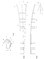
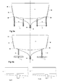
- Figure 3a shows the ship 1 of figure 1 in back view with the vertical fins 6 whereby on each side of the center line 5 two fins 6 are located and whereby between these two fins 6 one horizontal fin 7 is mounted.
- Figure 3b shows the same in side view.
- the propellers 8 and the rudders 9 are not shown.
- the propellers 8 and rudders 9 are located aft of the fins 6 and 7.
- various designs are possible, such as three propellers 8 as shown in figure 1, two propellers, two propellers with one waterjet, one propeller with two waterjets and also two or more waterjets as shown in figure 6 (discussed hereafter).
- Figures 4a and 4b show similar views of a further embodiment of the vertical fins 6 and the horizontal fins 7.
- the horizontal fin 7 extends from both sides of the vertical fin 6.
- the vertical fin 6 is located slightly away from side 19 so that the horizontal fin 7 does not extend outside the beam of the ship 1.
- the two horizontal fins 7 extending to both sides of the vertical fin 6 have a common axis and are connected to a single drive so that they move together.
- the horizontal fins 7 at starboard generate in a forward moving ship 1 an upwards directed force and the horizontal fins 7 at port generate a downwards directed force. These two forces form an anti-clockwise directed torque on the ship 1, which torque can be used to counteract forces that are for instance a consequence of waves.
- the front edge of the vertical fins 6 is shown as more or less vertical as in this way the water flow around the blade is most effective for creating a stabilizing force. It will be clear that the same conditions will apply if the vertical fins 6 are for instance vertical to the plane of the underside of the ship 1, as long as the front edge of the fin is more or less perpendicular to the water flow relative to the fin 6.
- the front edge of the vertical fins 6 can also be slightly swept back so that material folded around the front edge is guided towards the fin's end and comes free of the fin.
- the vertical fins 6 are combined with horizontal fins 7. It will be clear that for proper functioning of the vertical blades 6 this is no requirement.
- Figure 5 shows that the vertical fins 6 make a slight angle ⁇ with the center line 5 so that when the ship 1 moves in a straight line forward there are stable flow conditions around the fin 6 in the length of the fin 6 seen in flow direction and a correcting force is immediately available if waves push against the aft ship 10 and change the flow direction towards the fin 6 and flow conditions around the fin 6.
- angle ⁇ depends on the local flow conditions and so on the shape of the underside of the ship 1. In practice the value of angle ⁇ may be between 1 and 3 degrees or approximate 1,5 degrees.
- the blades of the horizontal fins 7 have a horizontal rotation axis, so ensuring similar aeration conditions along the length of the fin 7. Depending on the specific conditions this is not always essential. For instance in order to reduce flow resistance under normal conditions it might be advantageous to have the horizontal fin 7 seen perpendicular to the length parallel to the underside of the ship 1. In situations where there is no need to counteract the rolling of the ship 1 it is sufficient to have a horizontal fin 7 with a single drive, which can be over the full width of the ship 1 and which is only used for ensuring the proper trim of the ship 1. For stability this horizontal fin 7 can be supported in the center.
- Figure 6 shows the aft ship 10 of a further embodiment for which the hull is designed in similar way as in figure 1.
- the propulsion of the ship 1 in this embodiment is with waterjets.
- vertical fins 12 these vertical fins are more or less the same as the earlier discussed vertical fins 6 without the there added horizontal fins 7.
- water inlets 11 for intake of water that flows towards the waterjets and the water flows out of the nozzles 14 in the direction of a centre line 13.
- the centre lines 13 can be moved in a known way in a horizontal plane.
- For generating upward and downwards forces on the aft ship 10 the centre lines 13 can be moved in a similar way in a vertical plane around a horizontal axis.
- the control of the direction of the centre lines 13 is arranged in a similar way as the control of the horizontal fins 7 and is preferably connected to an auto pilot for active control having a control algorithm and applicable sensors for determining positions and movements of the ship.
Landscapes
- Ocean & Marine Engineering (AREA)
- Chemical & Material Sciences (AREA)
- Engineering & Computer Science (AREA)
- Combustion & Propulsion (AREA)
- Mechanical Engineering (AREA)
- Physics & Mathematics (AREA)
- Fluid Mechanics (AREA)
- Other Liquid Machine Or Engine Such As Wave Power Use (AREA)
- Hydraulic Turbines (AREA)
- Structures Of Non-Positive Displacement Pumps (AREA)
- Transition And Organic Metals Composition Catalysts For Addition Polymerization (AREA)
- Toys (AREA)
- Vibration Prevention Devices (AREA)
- Physical Water Treatments (AREA)
Abstract
The invention concerns a ship designed for use at high speed and/or heavy seas having a single long and slender hull, whereby the front half of the hull has more or less vertical sides, minimal flare in the bow sections and towards the bow an increase in draught at its center line combined with a more or less similar increase of freeboard and whereby the aft end of the hull has a flat or slightly V-shaped bottom with one or more propellers and/or waterjets as propulsion means. In accordance with the invention at the aft end of the hull on each side at some distance from the center line and preferably near the sides at least one stationary fin is provided.
Description
- The invention concerns a ship in accordance with the preamble of
claim 1. Such a ship is known from the publication Keuning, J.A.; Toxopeus, S.; Pinkster, J.; The effect of bow-shape on the seakeeping performance of a fast monohull; Proceedings of FAST 2001 conference, September 2001; page 197-206; ISBN 0 903055 70 8, publisher The Royal Institute of Naval Architects. In this publication the ship according to the invention is described as the AXE BOW design. The described disadvantage of the known design is that due to its deep bow and flat aft ship the course stability is insufficient. The proposed solution for this is to apply a center skeg or cutwater in the stern region. In practice this proposal does not bring the desired improvement as the draught near the bow is more than the draught of the cutwater so that the cutwater acts in disturbed water and does not generate sufficient stabilizing force in case of sideway movement of the aft of the hull due to a wave. In order to overcome this disadvantage the ship is in accordance withclaim 1. In this way there are at least two stationary fins that move under influence of the ships forward speed in more or less undisturbed water, so that they can generate sufficient stabilizing forces to ensure course stability. - In accordance with an embodiment of the invention the ship is according to
claim 2. By designing the fins in this way they increase the flow resistance of the ship only slightly and the more or less vertical front edge makes them very effective. - In accordance with an embodiment of the invention the ship is according to
claim 3. In this way it is easy to obtain minimal flare in the bow sections so that the displaced volume in waves increases only more or less linearly with the draught and so leads to better ship behavior in waves. - In accordance with an embodiment of the invention the ship is according to
claim 4. This fillet radius makes it possible to reduce the length of the ship and so reducing the wetted surface and the flow resistance without disadvantageously influencing the ships behavior in waves. - In accordance with an embodiment of the invention the ship is according to
claim 5. This improves the ships behavior in heavy seas as the added resistance in waves is reduced. - In accordance with an embodiment of the invention the ship is according to
claim 6. In this way the ship can be brought in a speed dependent trim position independent of the load or mass distribution in the ship, thereby reducing drag and improving propulsion efficiency. - In accordance with an embodiment of the invention the ship is according to
claim 7. By using water flow generated by the propellers or waterjets the adjustable upwards or downwards directed force is obtained independent from the ships speed. - In accordance with an embodiment of the invention the ship is according to
claim 8. By using the flow direction out of the nozzles both for steering and creating the adjustable upward or downward force a compact design is possible. - In accordance with an embodiment of the invention the ship is according to
claim 9. By using the water flow generated by the forward speed of the ship the adjustable upwards or downwards directed force is obtained in efficient way. - In accordance with an embodiment of the invention the ship is according to
claim 10. The combination of the stationary fins with the horizontal fin makes a compact design possible whereby when locating the horizontal fin at sufficient depth of the stationary fin aeration of the horizontal fin is prevented. - In accordance with an embodiment of the invention the ship is according to
claim 11. In this way the upwards or downwards directed forces can be adjusted in an easy way to varying circumstances such as forward speed, incoming waves and possibly also the dynamic movements of the ship. - In accordance with an embodiment of the invention the ship is according to
claim 12. In this way it is possible to generate with the upwards or downwards directed forces a torque in longitudinal direction of the hull which torque can minimize the rolling movements of the hull. - In accordance with an embodiment of the invention the ship is according to
claim 13. In this way the upwards and downwards directed forces can dynamically be adjusted dependent on the position and movements of the ship in the water. - In accordance with an embodiment of the invention the ship is according to
claim 14. In this way the hull is automatically held in the optimal attitude with the lowest resistance so improving the efficiency of the ship. - In accordance with an embodiment of the invention the ship is according to
claim 15. In this way the pitch, heave and/or roll motion are reduced in an easy way. - The invention will be explained in more detail below with reference to several exemplary embodiments by means of a drawing, in which:
- Figure 1 shows a perspective view of a ship according a first embodiment of the invention, whereby the propulsion means includes propellers,
- Figure 2 shows a body plan of the design of the ship according to the invention, whereby figure 2a shows the various cross sections, figure 2b shows the side view and figure 2c shows the bottom view,
- Figure 3 shows schematically the aft of the ship in accordance with figure 1 in back view and in side view,
- Figure 4 shows schematically the aft of the ship in accordance with a further embodiment of the invention in back view and in side view,
- Figure 5 shows schematically the bottom view of the aft of the ship of the previous embodiments and specifically the toe angle of the vertical fins, and
- Figure 6 shows a perspective view of an aft ship according to an further embodiment of the invention, whereby the propulsion means include waterjets.
- Figure 1 shows a
ship 1 which is designed in accordance with the body plan according to figure 2. Theship 1 is designed for high speeds and has a single long and slender hull withsides 19, whereby the length of the hull is at least five times the beam and for longer ships as much as seven to eight times the beam. In shorter ships the beam is relatively larger as the hull must include the propulsion means and a wider beam ensures that there remains sufficient stability. Theship 1 has one ormore propellers 8 and one ormore rudders 9. For manoeuvring there is abow thruster 4 near abow 3. The lay out on deck is as usual for instance with awheel house 2. - As can be seen in figure 2 the hull of the
ship 1 has a special design, in more detail the design is such that a reduction of the Froude Kriloff forces in particular in the foreship is achieved by minimizing the change in momentaneous submerged volume of the hull whilst it makes larger relative motions relative to the water level due to waves or the ships motions. This results in adesign applying sides 19 as much as feasible. A further measure in the design is to reduce the change in waterline beam of the sections in particular in the foreship whilst it makes the foresaid larger relative motions. This implies there is a minimal flare in the bow sections and abow 3 has a more or less vertical line or extends less than 30 degrees forward. By doing so the change of the added mass of the sections is minimized and with that also the changes in the hydrodynamic lift in the foreship are minimized. By increasing the freeboard and bringing thedeck line 15 higher towards thebow 3 in the foreship sufficient reserve buoyancy is guaranteed. - The amount of increased shear in the foreship, shown in figure 2 as
deck line 15, is dependent on ship size, speed and wave climate involved. A downwards slopingcentre line 5 towards the foreship prevents the sections there to leave and re-enter the water whilst the ship is performing larger relative motions. Thecentre line 5 is at it lowest near thebow 3 nearpoint 16 which indicates the maximum draught relative to awaterline 17. The amount of negative slope in thebottom 21 is dependent on ship size, speed and wave climate involved. The deadrise angle of the sections from bow to stern is carefully determined in order to minimize exciting forces and yet maintain sufficient hydrodynamic lift with minimal resistance. - Summarized the shape of the hull is such that the hull is long and slender, there is no flare in the bow sections and the
sides 19 at the bow sections are almost vertical. Near thebow 3 thesides 19 make an angle α seen in a horizontal plane which is smaller than 40 degrees. There is an increased sheer forward and down sloping centreline forward and the entry of thewaterlines 20 are rounded. In order to reduce the wetted surface thebow 3 is rounded with a radius R of at least 0,1m. Depending on the beam of the ship the radius can be at least 1% of the beam. - When applying this new hull shape additional measures must be taken for maintaining adequate yaw or course keeping stability and to prevent undesirable control problems in particular in following or stern quartering waves. The hull itself generates destabilizing yaw and sway forces and moments which may lead to these instabilities. By the introduction of fixed vertical stabilizing fins or
skegs 6 at the aft end of the hull these instabilities are prevented. Thefins 6 preferably have airfoil type section shapes and have reasonable aspects ratios to generate adequate lift to counteract the destabilizing effects in yaw and sway of the hull. They are designed to optimize the yaw stability in particular at the cost of minimal increase in resistance. Thefins 6 are located away from thecenter line 5 and preferably near thesides 19 so that they are away from the disturbed area in the water which is the result of themaximum draught 16 of thebow 3 which is much deeper in the water than anaft ship 10. - The restoring moment of the hull in pitch is relatively small when compared to similar craft. To a lesser extend this is also true for the restoring force in heave. The heave motion but in particular the pitch motion may be very effectively reduced by the application of one or more activated
horizontal fins 7 at theaft ship 10. Thesefins 7 generate positive or negative lift and can be adjusted manually, if used only for trim control, or be controlled by (on board) sensors and control algorithms. In the embodiment of figure 1 there are twohorizontal fins 7 which may work together and so bring forces on theaft ship 10 that counteract the heave and/or pitch of theship 1 and can bring it in its optimal trim. In another embodiment the twohorizontal fins 7 may be controlled in such a way that they create counter acting upward and downward forces and so create a torque in longitudinal direction on theship 1 that counteracts rolling so that under proper control the stability can be improved. - The submerged
horizontal fins 7, wetted on both sides, rely for the lift generation on both the high pressure and the suction side common for foils and they are preferably placed sufficiently deep below the water level to prevent ventilation or suction side cavitations along thefins 7. Specifically they can be used for active control of the trim angle in calm water dependent on the speed of theship 1 in order to yield optimum attitude of the ship, for active control of the pitch and heave motion by auto pilot and control algorithm and also by applying differential steering for port and starboard horizontal fins the rolling motion can be controlled. - Figure 3a shows the
ship 1 of figure 1 in back view with thevertical fins 6 whereby on each side of thecenter line 5 twofins 6 are located and whereby between these twofins 6 onehorizontal fin 7 is mounted. Figure 3b shows the same in side view. For reasons of clarity thepropellers 8 and therudders 9 are not shown. As can be seen in figure 1 thepropellers 8 andrudders 9 are located aft of thefins ship 1 various designs are possible, such as threepropellers 8 as shown in figure 1, two propellers, two propellers with one waterjet, one propeller with two waterjets and also two or more waterjets as shown in figure 6 (discussed hereafter). - Figures 4a and 4b show similar views of a further embodiment of the
vertical fins 6 and thehorizontal fins 7. In this embodiment thehorizontal fin 7 extends from both sides of thevertical fin 6. Thevertical fin 6 is located slightly away fromside 19 so that thehorizontal fin 7 does not extend outside the beam of theship 1. The twohorizontal fins 7 extending to both sides of thevertical fin 6 have a common axis and are connected to a single drive so that they move together. In the embodiment shown in figure 4 thehorizontal fins 7 at starboard generate in a forward movingship 1 an upwards directed force and thehorizontal fins 7 at port generate a downwards directed force. These two forces form an anti-clockwise directed torque on theship 1, which torque can be used to counteract forces that are for instance a consequence of waves. - The front edge of the
vertical fins 6 is shown as more or less vertical as in this way the water flow around the blade is most effective for creating a stabilizing force. It will be clear that the same conditions will apply if thevertical fins 6 are for instance vertical to the plane of the underside of theship 1, as long as the front edge of the fin is more or less perpendicular to the water flow relative to thefin 6. The front edge of thevertical fins 6 can also be slightly swept back so that material folded around the front edge is guided towards the fin's end and comes free of the fin. In the shown embodiments thevertical fins 6 are combined withhorizontal fins 7. It will be clear that for proper functioning of thevertical blades 6 this is no requirement. Figure 5 shows that thevertical fins 6 make a slight angle β with thecenter line 5 so that when theship 1 moves in a straight line forward there are stable flow conditions around thefin 6 in the length of thefin 6 seen in flow direction and a correcting force is immediately available if waves push against theaft ship 10 and change the flow direction towards thefin 6 and flow conditions around thefin 6. The value of angle β depends on the local flow conditions and so on the shape of the underside of theship 1. In practice the value of angle β may be between 1 and 3 degrees or approximate 1,5 degrees. - In the shown embodiments the blades of the
horizontal fins 7 have a horizontal rotation axis, so ensuring similar aeration conditions along the length of thefin 7. Depending on the specific conditions this is not always essential. For instance in order to reduce flow resistance under normal conditions it might be advantageous to have thehorizontal fin 7 seen perpendicular to the length parallel to the underside of theship 1. In situations where there is no need to counteract the rolling of theship 1 it is sufficient to have ahorizontal fin 7 with a single drive, which can be over the full width of theship 1 and which is only used for ensuring the proper trim of theship 1. For stability thishorizontal fin 7 can be supported in the center. - Figure 6 shows the
aft ship 10 of a further embodiment for which the hull is designed in similar way as in figure 1. The propulsion of theship 1 in this embodiment is with waterjets. For course stability there arevertical fins 12, these vertical fins are more or less the same as the earlier discussedvertical fins 6 without the there addedhorizontal fins 7. In the underside of the ship there arewater inlets 11 for intake of water that flows towards the waterjets and the water flows out of thenozzles 14 in the direction of acentre line 13. For steering thecentre lines 13 can be moved in a known way in a horizontal plane. For generating upward and downwards forces on theaft ship 10 thecentre lines 13 can be moved in a similar way in a vertical plane around a horizontal axis. The control of the direction of thecentre lines 13 is arranged in a similar way as the control of thehorizontal fins 7 and is preferably connected to an auto pilot for active control having a control algorithm and applicable sensors for determining positions and movements of the ship.
Claims (15)
- Ship designed for use at high speed and/or heavy seas having a single long and slender hull, whereby the front half of the hull has more or less vertical sides (19), minimal flare in the bow sections and towards the bow (3) an increase in draught at its center line (5) combined with a more or less similar increase of freeboard and whereby the aft end (10) of the hull has a flat or slightly V-shaped bottom with one or more propellers (8) and/or waterjets (14) as propulsion means characterized in that at the aft end (10) of the hull on each side at some distance from the center line (5) and preferably near the sides (19) at least one stationary fin (6;12) is mounted.
- Ship according to claim 1 whereby the stationary fins (6;12) have a more or less vertical or slightly swept back front edge and an airfoil type section shape.
- Ship according to claim 1 or 2 whereby the bow (3) has a more or less vertical stem (3).
- Ship according to claim 1, 2 or 3 whereby the sides (19) near the bow (3) seen in a horizontal section make a sharp angle (α) with a fillet radius (R) of at least 0,1 m.
- Ship according to claim 4 whereby the sharp angle (α) of the sides (19) near the bow (3) is less than 40 degrees.
- Ship according to one of the previous claims whereby the hull has at the aft end (10) of the hull adjustable force generating means (7;14) for generating an upward and/or downward force.
- Ship according to claim 6 whereby the adjustable force generating means include one or more flow guides (14) placed in water flow generated by the propulsion means (8;14) and which flow guides are rotatable around a horizontal axis.
- Ship according to claim 7 whereby the flow guides are formed by the nozzles (14) of the waterjets.
- Ship according to claim 6 whereby the adjustable force generating means include at least one more or less horizontal fin (7) placed beneath the bottom of the hull and which fin is rotatable around the longitudinal axis of the fin.
- Ship according to claim 9 whereby the or each horizontal fin (7) is attached to a stationary fin (6), preferably near its maximum depth.
- Ship according to one of the claims 6-10 whereby each flow guide (14) or each horizontal fin (7) has a drive for rotating the flow guide or the horizontal fin around its horizontal axis.
- Ship according to claim 11 whereby for flow guides (14) or horizontal fins (7) located at different sides of the hull, the drive for each flow guide or horizontal fin is independently controlled.
- Ship according to one of the claims 11-12 whereby the drives are controlled by a control system which is connected to one or more sensors for determining positions and/or movements of the hull.
- Ship according to claim 13 whereby the control system includes algorithm and control means for adjusting the drives in order to bring the hull in a speed dependent trim position.
- Ship according to claim 13 or 14 whereby the control system includes algorithm and control means for adjusting the drives in order to reduce wave generated pitch and/or heave and/or roll motion.
Priority Applications (22)
| Application Number | Priority Date | Filing Date | Title |
|---|---|---|---|
| EP06116487A EP1873051A1 (en) | 2006-06-30 | 2006-06-30 | Ship |
| PL07786969T PL2038167T3 (en) | 2006-06-30 | 2007-06-30 | Ship |
| AT07786969T ATE459529T1 (en) | 2006-06-30 | 2007-06-30 | SHIP |
| EP07786969A EP2038167B1 (en) | 2006-06-30 | 2007-06-30 | Ship |
| JP2009517235A JP5175281B2 (en) | 2006-06-30 | 2007-06-30 | boat |
| ES07786969T ES2342221T3 (en) | 2006-06-30 | 2007-06-30 | SHIP. |
| BRPI0713868-7A BRPI0713868B1 (en) | 2006-06-30 | 2007-06-30 | SHIP |
| AU2007264945A AU2007264945B2 (en) | 2006-06-30 | 2007-06-30 | Ship |
| CA2656119A CA2656119C (en) | 2006-06-30 | 2007-06-30 | Ship |
| PT07786969T PT2038167E (en) | 2006-06-30 | 2007-06-30 | Ship |
| CN2007800249578A CN101484351B (en) | 2006-06-30 | 2007-06-30 | Ship |
| PCT/EP2007/056614 WO2008000838A1 (en) | 2006-06-30 | 2007-06-30 | Ship |
| DK07786969.1T DK2038167T3 (en) | 2006-06-30 | 2007-06-30 | Ship |
| RU2009102980/11A RU2437797C2 (en) | 2006-06-30 | 2007-06-30 | Vessel |
| DE602007005134T DE602007005134D1 (en) | 2006-06-30 | 2007-06-30 | SHIP |
| UAA200900666A UA92649C2 (en) | 2006-06-30 | 2007-06-30 | ship |
| NO20085297A NO337654B1 (en) | 2006-06-30 | 2008-12-18 | Ship |
| MYPI20085202A MY147613A (en) | 2006-06-30 | 2008-12-19 | Ship |
| ZA200810864A ZA200810864B (en) | 2006-06-30 | 2008-12-23 | Ship |
| KR1020087031837A KR101377025B1 (en) | 2006-06-30 | 2008-12-29 | ship |
| US12/346,514 US8047148B2 (en) | 2006-06-30 | 2008-12-30 | Ship |
| CY20101100449T CY1110080T1 (en) | 2006-06-30 | 2010-05-21 | VESSEL |
Applications Claiming Priority (1)
| Application Number | Priority Date | Filing Date | Title |
|---|---|---|---|
| EP06116487A EP1873051A1 (en) | 2006-06-30 | 2006-06-30 | Ship |
Publications (1)
| Publication Number | Publication Date |
|---|---|
| EP1873051A1 true EP1873051A1 (en) | 2008-01-02 |
Family
ID=37507862
Family Applications (2)
| Application Number | Title | Priority Date | Filing Date |
|---|---|---|---|
| EP06116487A Withdrawn EP1873051A1 (en) | 2006-06-30 | 2006-06-30 | Ship |
| EP07786969A Active EP2038167B1 (en) | 2006-06-30 | 2007-06-30 | Ship |
Family Applications After (1)
| Application Number | Title | Priority Date | Filing Date |
|---|---|---|---|
| EP07786969A Active EP2038167B1 (en) | 2006-06-30 | 2007-06-30 | Ship |
Country Status (21)
| Country | Link |
|---|---|
| US (1) | US8047148B2 (en) |
| EP (2) | EP1873051A1 (en) |
| JP (1) | JP5175281B2 (en) |
| KR (1) | KR101377025B1 (en) |
| CN (1) | CN101484351B (en) |
| AT (1) | ATE459529T1 (en) |
| AU (1) | AU2007264945B2 (en) |
| BR (1) | BRPI0713868B1 (en) |
| CA (1) | CA2656119C (en) |
| CY (1) | CY1110080T1 (en) |
| DE (1) | DE602007005134D1 (en) |
| DK (1) | DK2038167T3 (en) |
| ES (1) | ES2342221T3 (en) |
| MY (1) | MY147613A (en) |
| NO (1) | NO337654B1 (en) |
| PL (1) | PL2038167T3 (en) |
| PT (1) | PT2038167E (en) |
| RU (1) | RU2437797C2 (en) |
| UA (1) | UA92649C2 (en) |
| WO (1) | WO2008000838A1 (en) |
| ZA (1) | ZA200810864B (en) |
Cited By (6)
| Publication number | Priority date | Publication date | Assignee | Title |
|---|---|---|---|---|
| CN102514681A (en) * | 2011-12-23 | 2012-06-27 | 深圳市海斯比船艇科技股份有限公司 | Dolabriform bow high-speed boat model adhered with wave-elimination-damping wings |
| CN101723054B (en) * | 2009-10-16 | 2013-01-09 | 庄学东 | Spherical twin-hull non-capsizing ship |
| CN101484353B (en) * | 2006-06-30 | 2013-09-18 | 代尔夫特科技大学 | Ship with bow control surface |
| CN104002939A (en) * | 2012-05-10 | 2014-08-27 | 赵凤银 | Aircraft carrier, vessel, submarine and offshore platform with efficient load-eliminating shake-stopping anti-overturning correction device |
| WO2016042527A1 (en) * | 2014-09-18 | 2016-03-24 | Cantiere Navale Vittoria S.P.A. | Hull for boats for high speed in irregular sea conditions |
| EP3583022A1 (en) * | 2017-02-17 | 2019-12-25 | BA Technologies Limited | Powerboat |
Families Citing this family (21)
| Publication number | Priority date | Publication date | Assignee | Title |
|---|---|---|---|---|
| EP1873051A1 (en) * | 2006-06-30 | 2008-01-02 | Technische Universiteit Delft | Ship |
| US8662000B2 (en) * | 2009-11-08 | 2014-03-04 | Ssp Technologies, Inc. | Stable offshore floating depot |
| RU2488510C2 (en) * | 2011-08-25 | 2013-07-27 | Российская Федерация, от имени которой выступает Министерство промышленности и торговли Российской Федерации (Минпромторг России) | High-speed vessel |
| CN102514684B (en) * | 2011-12-23 | 2014-12-10 | 深圳市海斯比船艇科技股份有限公司 | High-speed boat with axe-shaped bow and diving body |
| RU2493039C1 (en) * | 2012-02-02 | 2013-09-20 | Российская Федерация, От Имени Которой Выступает Министерство Промышленности И Торговли Российской Федерации | Surface single-hull displacement fast-speed ship |
| CN102700680B (en) * | 2012-06-08 | 2015-03-04 | 中国神华能源股份有限公司 | Displacement pilot boat |
| USD742805S1 (en) * | 2012-08-28 | 2015-11-10 | Ulstein Power & Control As | Ship's bridge |
| USD724517S1 (en) * | 2013-02-22 | 2015-03-17 | Philippe Starck | Yacht deck |
| RU2562086C2 (en) * | 2013-10-30 | 2015-09-10 | РОССИЙСКАЯ ФЕДЕРАЦИЯ, от имени которой выступает МИНИСТЕРСТВО ПРОМЫШЛЕННОСТИ И ТОРГОВЛИ РОССИЙСКОЙ ФЕДЕРАЦИИ "МИНПРОМТОРГ РОССИИ" | High-speed single-hull displacement surface ship stabiliser |
| US9751593B2 (en) | 2015-01-30 | 2017-09-05 | Peter Van Diepen | Wave piercing ship hull |
| RU2607136C2 (en) * | 2015-03-02 | 2017-01-10 | Василий Николаевич Храмушин | Fore end of high-speed surface ship or relatively low-speed civil ship of high thunderstorm navigability and ice flotation in autonomous navigation |
| RU2623348C1 (en) | 2015-12-24 | 2017-06-23 | Игнат Михайлович Водопьянов | Stabilized housing of the single-hull keeled wind driven/power sail ship |
| CN107351971A (en) * | 2017-06-27 | 2017-11-17 | 贺健元 | Submarine drag reduction tip cap, triangle water knockout drum |
| CN109367689B (en) * | 2018-10-09 | 2020-10-23 | 中船黄埔文冲船舶有限公司 | Design method of hull deck surface platform molded line |
| RU2701622C1 (en) * | 2019-01-17 | 2019-09-30 | Российская Федерация, от имени которой выступает Министерство обороны Российской Федерации | Surface single-hull high-speed vessel with wave-cutting contours |
| CN117326057A (en) * | 2020-03-07 | 2024-01-02 | 茂名高新技术产业开发区嘉舟创新科技有限公司 | Head-jet tail-jet water-borne airship |
| CN114179961A (en) * | 2020-09-15 | 2022-03-15 | 上海交通大学 | Attitude-adaptive water surface two-body unmanned platform |
| JP7527215B2 (en) * | 2021-02-04 | 2024-08-02 | 三菱重工マリタイムシステムズ株式会社 | Ships |
| CN113501099B (en) * | 2021-08-26 | 2022-12-02 | 哈尔滨工程大学 | A pitch-reducing channel propeller |
| USD1013040S1 (en) * | 2022-09-13 | 2024-01-30 | Ulstein Design & Solutions As | Ship |
| USD1096582S1 (en) * | 2023-08-08 | 2025-10-07 | Nerio Alessandri | Boat |
Citations (6)
| Publication number | Priority date | Publication date | Assignee | Title |
|---|---|---|---|---|
| NL9100048A (en) * | 1991-01-11 | 1992-08-03 | Scheepswerf Damen B V | Vessel stabilising fins mechanism - has interconnected, central controlled horizontal fins at right angles to rudders |
| EP0678445A1 (en) * | 1994-04-21 | 1995-10-25 | Petroleum Geo-Services Ag | Hull configuration |
| JPH08324485A (en) * | 1995-06-02 | 1996-12-10 | Hitachi Zosen Corp | Motion control device and motion control method in ship |
| US6171159B1 (en) * | 1999-09-07 | 2001-01-09 | The United States Of America As Represented By The Secretary Of The Navy | Steering and backing systems for waterjet craft with underwater discharge |
| US20050011427A1 (en) * | 2003-07-18 | 2005-01-20 | Lockheed Martin Corporation | Two degree of freedom rudder/stabilizer for waterborne vessels |
| WO2005012075A1 (en) * | 2003-08-01 | 2005-02-10 | Rolls-Royce Marine As | Device for increasing the yaw stability in ships |
Family Cites Families (15)
| Publication number | Priority date | Publication date | Assignee | Title |
|---|---|---|---|---|
| US1211316A (en) * | 1916-09-12 | 1917-01-02 | Niels Jantzen | Boat's rudder. |
| US2342707A (en) | 1941-01-17 | 1944-02-29 | Troyer Nelson | Boat |
| US2363335A (en) * | 1942-07-23 | 1944-11-21 | Katcher Morris | Steering means for watercraft |
| US3889623A (en) * | 1974-01-31 | 1975-06-17 | Robert W Arnold | Jet propulsion unit for boats |
| NO153560C (en) * | 1983-07-19 | 1986-04-16 | Roar Ramde | HULL FORM. |
| DE3539081A1 (en) * | 1985-11-04 | 1987-04-09 | Joachim Gerhard Dietel | Knife-edge bow on the hull of a ship |
| JPS63312298A (en) | 1987-01-23 | 1988-12-20 | Mitsubishi Heavy Ind Ltd | Steering gear |
| GB9011007D0 (en) * | 1990-05-16 | 1990-10-10 | Dowty Woodville Polymer Engine | Means to enhance the flow of fluid |
| AU7549694A (en) * | 1993-06-17 | 1995-01-17 | Vehicle Research Corporation | Surfing ship transition system |
| RU2155693C1 (en) * | 1999-11-09 | 2000-09-10 | Центральный научно-исследовательский институт им. акад. А.Н. Крылова | Surface single-hulled displacement-type high-speed vessel |
| CA2359532A1 (en) * | 2001-09-27 | 2003-03-27 | Peter J. Van Diepen | Monohull wave piercing bow |
| WO2006018303A1 (en) * | 2004-08-19 | 2006-02-23 | Hanse Yachts Gmbh & Co. Kg | Floating body |
| NO324744B3 (en) * | 2005-03-09 | 2012-01-10 | Ulstein Design & Solutions As | Device for displacement of a displacement type vessel. |
| EP1873055A1 (en) * | 2006-06-30 | 2008-01-02 | Technische Universiteit Delft | Ship with bow control surface |
| EP1873051A1 (en) * | 2006-06-30 | 2008-01-02 | Technische Universiteit Delft | Ship |
-
2006
- 2006-06-30 EP EP06116487A patent/EP1873051A1/en not_active Withdrawn
-
2007
- 2007-06-30 PL PL07786969T patent/PL2038167T3/en unknown
- 2007-06-30 DE DE602007005134T patent/DE602007005134D1/en active Active
- 2007-06-30 AT AT07786969T patent/ATE459529T1/en not_active IP Right Cessation
- 2007-06-30 WO PCT/EP2007/056614 patent/WO2008000838A1/en not_active Ceased
- 2007-06-30 UA UAA200900666A patent/UA92649C2/en unknown
- 2007-06-30 CA CA2656119A patent/CA2656119C/en active Active
- 2007-06-30 BR BRPI0713868-7A patent/BRPI0713868B1/en active IP Right Grant
- 2007-06-30 EP EP07786969A patent/EP2038167B1/en active Active
- 2007-06-30 ES ES07786969T patent/ES2342221T3/en active Active
- 2007-06-30 CN CN2007800249578A patent/CN101484351B/en active Active
- 2007-06-30 PT PT07786969T patent/PT2038167E/en unknown
- 2007-06-30 JP JP2009517235A patent/JP5175281B2/en active Active
- 2007-06-30 AU AU2007264945A patent/AU2007264945B2/en active Active
- 2007-06-30 DK DK07786969.1T patent/DK2038167T3/en active
- 2007-06-30 RU RU2009102980/11A patent/RU2437797C2/en active
-
2008
- 2008-12-18 NO NO20085297A patent/NO337654B1/en unknown
- 2008-12-19 MY MYPI20085202A patent/MY147613A/en unknown
- 2008-12-23 ZA ZA200810864A patent/ZA200810864B/en unknown
- 2008-12-29 KR KR1020087031837A patent/KR101377025B1/en active Active
- 2008-12-30 US US12/346,514 patent/US8047148B2/en active Active
-
2010
- 2010-05-21 CY CY20101100449T patent/CY1110080T1/en unknown
Patent Citations (6)
| Publication number | Priority date | Publication date | Assignee | Title |
|---|---|---|---|---|
| NL9100048A (en) * | 1991-01-11 | 1992-08-03 | Scheepswerf Damen B V | Vessel stabilising fins mechanism - has interconnected, central controlled horizontal fins at right angles to rudders |
| EP0678445A1 (en) * | 1994-04-21 | 1995-10-25 | Petroleum Geo-Services Ag | Hull configuration |
| JPH08324485A (en) * | 1995-06-02 | 1996-12-10 | Hitachi Zosen Corp | Motion control device and motion control method in ship |
| US6171159B1 (en) * | 1999-09-07 | 2001-01-09 | The United States Of America As Represented By The Secretary Of The Navy | Steering and backing systems for waterjet craft with underwater discharge |
| US20050011427A1 (en) * | 2003-07-18 | 2005-01-20 | Lockheed Martin Corporation | Two degree of freedom rudder/stabilizer for waterborne vessels |
| WO2005012075A1 (en) * | 2003-08-01 | 2005-02-10 | Rolls-Royce Marine As | Device for increasing the yaw stability in ships |
Non-Patent Citations (3)
| Title |
|---|
| KEUNING, JA, PINKSTER, J & WALREE, F VAN, 18 September 2002, UNIVERSITY OF NAPLES, NAPLES, XP008073064 * |
| KEUNING, JA, TOXOPEUS, S & PINKSTER,J: "THE EFFECT OF BOWSHAPE ON THE SEAKEEPEING PERFORMANCE OF A FAST MONOHULL", 4 September 2001, THE ROYAL INSTITUTE OF NAVAL ARCHITECTS, LONDON, XP008073025 * |
| KEUNING,J.A.; TOXOPEUS,S.; PINKSTER,J.: "The effect of bowshape on the seakeeping performance of a fast monohull. Proceedings of FAST 2001 conference.", September 2001, THE ROYAL INSTITUTE OF NAVAL ARCHITECTS., ISBN: 0-903055-70-8, pages: 197 - 206 |
Cited By (6)
| Publication number | Priority date | Publication date | Assignee | Title |
|---|---|---|---|---|
| CN101484353B (en) * | 2006-06-30 | 2013-09-18 | 代尔夫特科技大学 | Ship with bow control surface |
| CN101723054B (en) * | 2009-10-16 | 2013-01-09 | 庄学东 | Spherical twin-hull non-capsizing ship |
| CN102514681A (en) * | 2011-12-23 | 2012-06-27 | 深圳市海斯比船艇科技股份有限公司 | Dolabriform bow high-speed boat model adhered with wave-elimination-damping wings |
| CN104002939A (en) * | 2012-05-10 | 2014-08-27 | 赵凤银 | Aircraft carrier, vessel, submarine and offshore platform with efficient load-eliminating shake-stopping anti-overturning correction device |
| WO2016042527A1 (en) * | 2014-09-18 | 2016-03-24 | Cantiere Navale Vittoria S.P.A. | Hull for boats for high speed in irregular sea conditions |
| EP3583022A1 (en) * | 2017-02-17 | 2019-12-25 | BA Technologies Limited | Powerboat |
Also Published As
| Publication number | Publication date |
|---|---|
| KR20090051008A (en) | 2009-05-20 |
| RU2009102980A (en) | 2010-08-10 |
| BRPI0713868B1 (en) | 2020-09-29 |
| JP5175281B2 (en) | 2013-04-03 |
| BRPI0713868A2 (en) | 2012-12-18 |
| CN101484351A (en) | 2009-07-15 |
| PL2038167T3 (en) | 2010-08-31 |
| DE602007005134D1 (en) | 2010-04-15 |
| EP2038167B1 (en) | 2010-03-03 |
| ZA200810864B (en) | 2009-10-28 |
| EP2038167A1 (en) | 2009-03-25 |
| CA2656119A1 (en) | 2008-01-03 |
| MY147613A (en) | 2012-12-31 |
| CA2656119C (en) | 2013-01-22 |
| US8047148B2 (en) | 2011-11-01 |
| UA92649C2 (en) | 2010-11-25 |
| ES2342221T3 (en) | 2010-07-02 |
| CY1110080T1 (en) | 2015-01-14 |
| NO337654B1 (en) | 2016-05-23 |
| AU2007264945B2 (en) | 2012-05-03 |
| DK2038167T3 (en) | 2010-06-07 |
| RU2437797C2 (en) | 2011-12-27 |
| CN101484351B (en) | 2012-06-13 |
| AU2007264945A1 (en) | 2008-01-03 |
| JP2009541138A (en) | 2009-11-26 |
| NO20085297L (en) | 2009-03-27 |
| KR101377025B1 (en) | 2014-03-20 |
| ATE459529T1 (en) | 2010-03-15 |
| WO2008000838A1 (en) | 2008-01-03 |
| US20090158989A1 (en) | 2009-06-25 |
| PT2038167E (en) | 2010-06-11 |
Similar Documents
| Publication | Publication Date | Title |
|---|---|---|
| EP2038167B1 (en) | Ship | |
| EP2040978B1 (en) | Ship with bow control surface | |
| US4915048A (en) | Vessel with improved hydrodynamic performance | |
| US6138602A (en) | Catamaran--V boat hull | |
| AU621822B2 (en) | Vessel with improved hydrodynamic performance | |
| EP4126652A1 (en) | Vessel with stern positioned foil to reduce wave resistance | |
| US8286570B2 (en) | Hull for a marine vessel | |
| JP4530505B2 (en) | Ship stern flap device | |
| US12428107B1 (en) | Modular keel | |
| US9783265B2 (en) | Foil-assisted catamaran marine craft |
Legal Events
| Date | Code | Title | Description |
|---|---|---|---|
| PUAI | Public reference made under article 153(3) epc to a published international application that has entered the european phase |
Free format text: ORIGINAL CODE: 0009012 |
|
| AK | Designated contracting states |
Kind code of ref document: A1 Designated state(s): AT BE BG CH CY CZ DE DK EE ES FI FR GB GR HU IE IS IT LI LT LU LV MC NL PL PT RO SE SI SK TR |
|
| AX | Request for extension of the european patent |
Extension state: AL BA HR MK YU |
|
| AKX | Designation fees paid | ||
| REG | Reference to a national code |
Ref country code: DE Ref legal event code: 8566 |
|
| STAA | Information on the status of an ep patent application or granted ep patent |
Free format text: STATUS: THE APPLICATION IS DEEMED TO BE WITHDRAWN |
|
| 18D | Application deemed to be withdrawn |
Effective date: 20080703 |