EP1873020A1 - Integrated vehicle crash sensing system and method - Google Patents
Integrated vehicle crash sensing system and method Download PDFInfo
- Publication number
- EP1873020A1 EP1873020A1 EP07075521A EP07075521A EP1873020A1 EP 1873020 A1 EP1873020 A1 EP 1873020A1 EP 07075521 A EP07075521 A EP 07075521A EP 07075521 A EP07075521 A EP 07075521A EP 1873020 A1 EP1873020 A1 EP 1873020A1
- Authority
- EP
- European Patent Office
- Prior art keywords
- sensing
- vehicle
- linear acceleration
- crash
- axis
- Prior art date
- Legal status (The legal status is an assumption and is not a legal conclusion. Google has not performed a legal analysis and makes no representation as to the accuracy of the status listed.)
- Withdrawn
Links
- 238000000034 method Methods 0.000 title claims abstract description 22
- 230000001133 acceleration Effects 0.000 claims abstract description 113
- 238000001914 filtration Methods 0.000 claims description 6
- 238000001514 detection method Methods 0.000 description 10
- 230000003750 conditioning effect Effects 0.000 description 8
- 230000006870 function Effects 0.000 description 5
- 238000004364 calculation method Methods 0.000 description 4
- 238000010586 diagram Methods 0.000 description 4
- 230000008569 process Effects 0.000 description 3
- 230000003321 amplification Effects 0.000 description 2
- 230000003466 anti-cipated effect Effects 0.000 description 2
- 230000010354 integration Effects 0.000 description 2
- 238000003199 nucleic acid amplification method Methods 0.000 description 2
- 230000002411 adverse Effects 0.000 description 1
- 230000009977 dual effect Effects 0.000 description 1
- 230000000694 effects Effects 0.000 description 1
- 230000008030 elimination Effects 0.000 description 1
- 238000003379 elimination reaction Methods 0.000 description 1
- 230000005055 memory storage Effects 0.000 description 1
- 238000012986 modification Methods 0.000 description 1
- 230000004048 modification Effects 0.000 description 1
Images


Classifications
-
- B—PERFORMING OPERATIONS; TRANSPORTING
- B60—VEHICLES IN GENERAL
- B60R—VEHICLES, VEHICLE FITTINGS, OR VEHICLE PARTS, NOT OTHERWISE PROVIDED FOR
- B60R21/00—Arrangements or fittings on vehicles for protecting or preventing injuries to occupants or pedestrians in case of accidents or other traffic risks
- B60R21/01—Electrical circuits for triggering passive safety arrangements, e.g. airbags, safety belt tighteners, in case of vehicle accidents or impending vehicle accidents
- B60R21/013—Electrical circuits for triggering passive safety arrangements, e.g. airbags, safety belt tighteners, in case of vehicle accidents or impending vehicle accidents including means for detecting collisions, impending collisions or roll-over
- B60R21/0132—Electrical circuits for triggering passive safety arrangements, e.g. airbags, safety belt tighteners, in case of vehicle accidents or impending vehicle accidents including means for detecting collisions, impending collisions or roll-over responsive to vehicle motion parameters, e.g. to vehicle longitudinal or transversal deceleration or speed value
-
- B—PERFORMING OPERATIONS; TRANSPORTING
- B60—VEHICLES IN GENERAL
- B60R—VEHICLES, VEHICLE FITTINGS, OR VEHICLE PARTS, NOT OTHERWISE PROVIDED FOR
- B60R21/00—Arrangements or fittings on vehicles for protecting or preventing injuries to occupants or pedestrians in case of accidents or other traffic risks
- B60R21/01—Electrical circuits for triggering passive safety arrangements, e.g. airbags, safety belt tighteners, in case of vehicle accidents or impending vehicle accidents
- B60R21/013—Electrical circuits for triggering passive safety arrangements, e.g. airbags, safety belt tighteners, in case of vehicle accidents or impending vehicle accidents including means for detecting collisions, impending collisions or roll-over
- B60R21/0132—Electrical circuits for triggering passive safety arrangements, e.g. airbags, safety belt tighteners, in case of vehicle accidents or impending vehicle accidents including means for detecting collisions, impending collisions or roll-over responsive to vehicle motion parameters, e.g. to vehicle longitudinal or transversal deceleration or speed value
- B60R21/01332—Electrical circuits for triggering passive safety arrangements, e.g. airbags, safety belt tighteners, in case of vehicle accidents or impending vehicle accidents including means for detecting collisions, impending collisions or roll-over responsive to vehicle motion parameters, e.g. to vehicle longitudinal or transversal deceleration or speed value by frequency or waveform analysis
-
- B—PERFORMING OPERATIONS; TRANSPORTING
- B60—VEHICLES IN GENERAL
- B60R—VEHICLES, VEHICLE FITTINGS, OR VEHICLE PARTS, NOT OTHERWISE PROVIDED FOR
- B60R21/00—Arrangements or fittings on vehicles for protecting or preventing injuries to occupants or pedestrians in case of accidents or other traffic risks
- B60R21/01—Electrical circuits for triggering passive safety arrangements, e.g. airbags, safety belt tighteners, in case of vehicle accidents or impending vehicle accidents
- B60R21/013—Electrical circuits for triggering passive safety arrangements, e.g. airbags, safety belt tighteners, in case of vehicle accidents or impending vehicle accidents including means for detecting collisions, impending collisions or roll-over
- B60R21/0132—Electrical circuits for triggering passive safety arrangements, e.g. airbags, safety belt tighteners, in case of vehicle accidents or impending vehicle accidents including means for detecting collisions, impending collisions or roll-over responsive to vehicle motion parameters, e.g. to vehicle longitudinal or transversal deceleration or speed value
- B60R21/01332—Electrical circuits for triggering passive safety arrangements, e.g. airbags, safety belt tighteners, in case of vehicle accidents or impending vehicle accidents including means for detecting collisions, impending collisions or roll-over responsive to vehicle motion parameters, e.g. to vehicle longitudinal or transversal deceleration or speed value by frequency or waveform analysis
- B60R21/01336—Electrical circuits for triggering passive safety arrangements, e.g. airbags, safety belt tighteners, in case of vehicle accidents or impending vehicle accidents including means for detecting collisions, impending collisions or roll-over responsive to vehicle motion parameters, e.g. to vehicle longitudinal or transversal deceleration or speed value by frequency or waveform analysis using filtering
-
- B—PERFORMING OPERATIONS; TRANSPORTING
- B60—VEHICLES IN GENERAL
- B60R—VEHICLES, VEHICLE FITTINGS, OR VEHICLE PARTS, NOT OTHERWISE PROVIDED FOR
- B60R21/00—Arrangements or fittings on vehicles for protecting or preventing injuries to occupants or pedestrians in case of accidents or other traffic risks
- B60R2021/0002—Type of accident
-
- B—PERFORMING OPERATIONS; TRANSPORTING
- B60—VEHICLES IN GENERAL
- B60W—CONJOINT CONTROL OF VEHICLE SUB-UNITS OF DIFFERENT TYPE OR DIFFERENT FUNCTION; CONTROL SYSTEMS SPECIALLY ADAPTED FOR HYBRID VEHICLES; ROAD VEHICLE DRIVE CONTROL SYSTEMS FOR PURPOSES NOT RELATED TO THE CONTROL OF A PARTICULAR SUB-UNIT
- B60W30/00—Purposes of road vehicle drive control systems not related to the control of a particular sub-unit, e.g. of systems using conjoint control of vehicle sub-units
- B60W30/02—Control of vehicle driving stability
- B60W30/04—Control of vehicle driving stability related to roll-over prevention
Definitions
- the present invention generally relates to vehicle crash sensing, and more particularly relates to an integrated sensing system capable of sensing multiple crash events of the vehicle.
- Automotive vehicles are generally equipped with various restraint devices that deploy in the event that a vehicle is involved in a crash, such as a forward collision, a rear collision, a side (lateral) collision or a rollover.
- restraint devices For example, air bags, side curtains, seatbelt pretensioners, pop-up roll bars and other devices can be deployed when certain crash events are detected.
- These and other restraint devices require timely deployment to mitigate adverse effects to occupants in the vehicle.
- the vehicle dynamics To achieve timely deployment of restraint devices, the vehicle dynamics generally must be monitored and a decision must be made to determine whether some type of vehicle crash is anticipated to occur or is occurring.
- Various vehicle crash sensing systems employ sensors to sense dynamic conditions of the vehicle.
- a conventional crash sensing system may employ inertial sensors for sensing linear acceleration and/or angular velocity.
- Some conventional crash sensing systems are designed to detect only a frontal crash event.
- Other crash sensing systems have been designed to detect other vehicle crash events such as a side impact crash, a rear impact crash and vehicle rollover events.
- Each type of crash event detection generally employs inertial sensing requirements that are unique to that type of crash event. These requirements generally place constraints on the range, resolution and placement within the vehicle of each type of inertial sensor. Consequently, increasing the types of crash events that can be detected for a vehicle necessarily increases the number of sensors that are generally required to detect those crash events, and thereby results in an increase in the cost of the overall crash detection systems.
- a conventional vehicle side impact crash detection system may employ a single linear accelerometer, the output of which is processed by a side crash event algorithm.
- a separate and distinct rollover crash sensing system may employ another separate and distinct accelerometer along with an angular rate sensor, the outputs of which are processed by a rollover crash event algorithm.
- the two separate crash sensing systems typically employ separate inertial acceleration sensors that are each calibrated for a specific crash event and are not integrated.
- a vehicle crash sensing system that integrates one or more inertial sensors into one crash sensing system capable of detecting multiple crash events.
- the vehicle crash sensing system includes a linear acceleration sensor located on a vehicle for sensing linear acceleration along a first sensing axis and generating a linear acceleration signal.
- the system has crash sensing logic for determining a crash event along the first sensing axis as a function of the sensed linear acceleration.
- the system also has signal processing circuitry for processing the linear acceleration signal and generating a processed linear acceleration signal.
- the system has an angular rate sensor located on the vehicle for sensing an angular roll rate of the vehicle about a second sensing axis and generating a roll rate signal.
- the system further includes rollover crash sensing logic for determining a rollover event of the vehicle about the second sensing axis as a function of the processed linear acceleration signal and the roll rate signal.
- a method of detecting a crash event of a vehicle due to at least one of an impact crash event and a rollover event includes the step of sensing linear acceleration along a first sensing axis of the vehicle with a first linear acceleration sensor and generating a sensed linear acceleration signal. The method also includes the step of sensing a crash event along the first sensing axis as a function of the sensed linear acceleration signal. The method includes the step of processing the linear acceleration signal with signal processing circuitry to generate a processed linear acceleration signal. The method also includes the step of sensing an angular roll rate of the vehicle about a second sensing axis and generating a roll rate signal. The method further includes the step of determining a rollover event of the vehicle about the second sensing axis as a function of the processed linear acceleration signal and the roll rate signal.
- a vehicle 10 is generally illustrated equipped with a vehicle crash sensing system 20 for detecting either or both of an impact crash event and a rollover event of the vehicle 10.
- the vehicle 10 shown is a wheeled automotive vehicle generally shown having four wheels 12, 14, 16 and 18 for travelling on the ground, such as a roadway.
- the vehicle crash sensing system 20 may be contained in a module on the automotive vehicle 10 or may have components at various locations onboard the vehicle 10.
- the crash sensing system 20 has inertial sensors arranged to detect a side crash event along the lateral Y-axis of the vehicle 10 and a rollover crash event about the longitudinal X-axis of the vehicle 10, according to the embodiments shown.
- the vehicle crash sensing system 20 may be configured with sensors arranged to detect linear crash events and rollover events about any desired axes.
- a vehicle rollover event may include side-to-side rotation of the vehicle 10 about the longitudinal axis, shown as the X-axis, of the vehicle 10, commonly referred to as “vehicle rollover,” or back-to-front rotation of the vehicle 10 about the vehicle lateral axis, shown as the Y-axis, commonly referred to as a “vehicle pitchover,” or a combination of rollover and pitchover.
- rollover is generally used to refer to either a rollover event or a pitchover event.
- an impact crash event may include a side impact crash event of the vehicle 10 along the lateral Y-axis, a frontal or rear impact crash event along the X-axis, or other impact crash events occurring along other sensing axes.
- the vehicle crash sensing system 20 is designed to be located on the vehicle 10 to sense vehicle dynamics, particularly linear acceleration in a direction along a first sensing axis, and an angular rate (velocity) of the vehicle 10 about a second sensing axis.
- the first sensing axis e.g., Y-axis
- the second sensing axis e.g., X-axis
- linear acceleration and angular rate may be sensed in other first and second sensing axes according to other embodiments.
- a linear accelerometer 22 shown oriented on the vehicle 10 to sense linear acceleration A Y along the lateral Y-axis.
- a suitable linear accelerometer is Model No. ADXL78 commercially available from Analog Devices, Inc., rated at 50 g.
- an angular roll rate sensor 32 arranged, according to the first embodiment, on the vehicle 10 to sense angular roll rate about the longitudinal X-axis of the vehicle 10.
- a suitable angular rate sensor is Model No. EWTZGC250, commercially available from Panasonic.
- the linear accelerometer 22 and angular roll rate sensor 32 may be located at any of a number of locations on the vehicle 10 to sense linear acceleration along the lateral Y-axis and angular rate about the longitudinal X-axis, respectively.
- the linear accelerometer 22 may be mounted in the vehicle passenger compartment, in a vehicle door or on a structural support of the vehicle 10, such as the A-pillar, B-pillar or C-pillar.
- the angular roll rate sensor 32 may be mounted in the vehicle passenger compartment near the center, according to one example, or elsewhere onboard the vehicle 10.
- the liner accelerometer 22 and angular roll rate sensor 32 are integrated into a single vehicle crash sensing system 20 to sense either or both of a side impact crash event and a rollover event according to the embodiment shown and described herein.
- the vehicle crash sensing system 20 employs the linear accelerometer 22 to generate a linear acceleration A Y that is employed both by a side crash event algorithm 50 and a rollover crash event algorithm 70.
- the vehicle crash sensing system 20 therefore employs the linear accelerometer 20 in a manner that allows for sensing multiple crash events, thereby eliminating the need for separate and distinct acceleration sensors.
- the vehicle crash sensing system 20 has a controller, shown as a microprocessor control unit (MCU) 25, having a microprocessor 24 and memory 34. Stored within memory 34 are the side crash event algorithm 50 and rollover crash event algorithm 70.
- the microprocessor 24 may include any known analog and/or digital processing circuitry capable of executing the side crash event algorithm 50 and rollover crash event algorithm 70.
- Memory 34 may include conventional memory storage medium such as electrically erasable programmable read-only memory (EEPROM) or random access memory (RAM) that may store various program calibrations and routines for performing the crash sensing detection.
- the MCU 25 may be a dedicated crash sensing controller or may be implemented on a shared controller.
- the vehicle crash sensing system 20 senses a linear impact crash event, such as a side crash event, by processing the linear acceleration signal A Y output from the linear accelerometer 22.
- a linear impact crash event such as a side crash event
- the linear accelerometer 22 is oriented along the lateral Y-axis of the vehicle 10.
- the output of the linear accelerometer 22 is shown input to the side crash event algorithm 50.
- Any of a number of side crash event algorithms 50 may be employed to sense the presence of a side impact crash event.
- a side crash event algorithm 50 is shown in FIG. 3.
- the crash sensing system 20 employs signal conditioning circuitry 26 for processing the sensed acceleration signal A Y output from the linear accelerometer 22 and outputs a processed linear acceleration signal to the rollover crash event algorithm 70.
- the signal conditioning circuitry 26 enables the use of a single accelerometer 22 that is generally configured for use to detect a side impact crash event to also be employed to detect a vehicle rollover crash event, according to one embodiment of the present invention.
- the signal conditioning circuitry 26 processes the linear acceleration signal output to alter the range, resolution and/or bandwidth of the inertial linear acceleration sensor 22 used for the side impact crash event in order to provide linear acceleration data that meets the requirements for sensing a second crash-type event, namely a vehicle rollover event.
- the signal conditioning circuitry 26 therefore allows for elimination of duplicative sensors by generating the appropriately processed linear acceleration signal.
- the signal conditioning circuitry 26 is shown including an amplifier 28 coupled to the output of linear accelerometer 22, and a band-pass filter 26 coupled to the output of the amplifier 28.
- the amplifier 28 amplifies the sensed linear acceleration signal A Y by an amplification gain, such as 10X according to one example.
- the band-pass filter 30 has a pass band, such as a frequency range of 0.1 Hz to 50 Hz, according to one embodiment. According to another embodiment, the band-pass filter 30 may have the low frequency portion of the signal removed by the subtraction of the output of a linear integration function tracking the low band portion of the signal.
- the band-pass filter 30 therefore filters low frequencies below 0.1 Hz and high frequencies above 50 Hz, according to this embodiment, to reduce or eliminate noise.
- the amplified and filtered linear acceleration signal is then input to the rollover crash event algorithm 70.
- the digital signal conditioning circuitry 26 may be implemented in analog circuitry, according to one embodiment. According to another embodiment, the signal conditioning circuitry 26 may be implemented in digital circuitry. According to other embodiments, a combination of analog and digital circuitry may be employed in the signal conditioning circuitry 26 to process the sensed linear acceleration signal A Y and make the processed linear acceleration signal available as an input to the rollover crash event algorithm 70.
- the vehicle crash sensing system 20 further includes an angular roll rate sensor 32 for sensing angular rate (velocity) ⁇ x of the vehicle 10 about a second sensing axis.
- the angular roll rate sensor 32 is oriented to sense angular rate about the longitudinal X-axis of the vehicle 10, and generates a sensed angular rate signal ⁇ x indicative thereof. Any of a number of angular rate sensors 32 may be employed to sense the vehicle angular roll rate ⁇ x .
- Angular roll rate sensor 32 may be oriented about another sensing axis, such as the lateral Y-axis to determine a pitch rate of the vehicle 10.
- the rollover crash event algorithm 34 therefore receives as inputs the processed linear acceleration signal and the sensed angular roll rate signal.
- the rollover crash event algorithm 70 processes the linear acceleration and angular rate signals and determines an anticipated or actual rollover of the vehicle 10 about the longitudinal X-axis. According to other embodiments, the rollover crash event algorithm 70 may determine a rollover event of the vehicle 10 about other axes, such as the lateral Y-axis, also referred to as a pitchover event. Any of a number of rollover crash event algorithms may be employed.
- a rollover crash event algorithm 70 is shown in FIG. 4.
- a vehicle 10 is illustrated employing a vehicle crash sensing system 20 according to a second embodiment of the present invention.
- the vehicle crash sensing system 20 according to the second invention employs first and second linear acceleration sensors (accelerometers) 40 and 42, each oriented at an angle offset from each other and in a direction offset from both the longitudinal X-axis and lateral Y-axis of the vehicle 10.
- the first linear accelerometer 40 is oriented in a first axis at an angle ⁇ offset by -45° from the longitudinal X-axis of the vehicle 10 as shown.
- the second linear accelerometer 42 is oriented in a second axis at an angle ⁇ offset by +45° from the longitudinal X-axis of the vehicle 10.
- first and second linear accelerometers 40 and 42 are arranged orthogonal (90°) relative to each other and are offset from both the longitudinal X-axis and lateral Y-axis of the vehicle 10 such that each of accelerometers 40 and 42 senses components of linear acceleration A x and A Y in each of the respective longitudinal X-axis and lateral Y-axis of the vehicle 10.
- first and second linear accelerometers 40 and 42 in the system 20 advantageously sense linear accelerations A 1 and A 2 about the two separate axes.
- the accelerometers 40 and 42 may include an integrated dual axis accelerometer, such as Model No. ADXL278, commercially available from Analog Devices, Inc.
- the vehicle crash sensing system 20 employs signal processing circuitry 26 that includes an arithmetic logic device 44, such as a summer or a subtractor for either summing or subtracting the sensed linear acceleration signals A 1 and A 2 output from the first and second linear accelerometers 40 and 42.
- an arithmetic logic device 44 such as a summer or a subtractor for either summing or subtracting the sensed linear acceleration signals A 1 and A 2 output from the first and second linear accelerometers 40 and 42.
- the sensed linear acceleration signals from each of the first and second linear accelerometers 40 and 42 are subtracted such that the difference provides a signal indicative of the lateral acceleration in the Y-axis.
- the arithmetically summed output of the sensed acceleration signals A 1 and A 2 provides the lateral Y-axis linear acceleration component that is input to a side crash event algorithm 50 for processing as discussed above.
- the signal processing circuitry 26 in the vehicle crash sensing system 10 further employs an amplifier 28 for amplifying arithmetic summed linear acceleration signal, and a band-pass filter 30 for filtering amplified linear acceleration signals.
- the amplified and filtered linear acceleration signal is then input to a rollover crash event algorithm 70.
- an angular roll rate signal ⁇ X sensed by angular roll rate sensor 32 oriented to sense angular acceleration about the longitudinal X-axis is also input to the rollover crash events algorithm 70 and is processed as discussed above in connection with the first embodiment.
- the vehicle crash sensing system 20 is shown employing two linear accelerometers 40 and 42 each rated as 50 g acceleration sensors that produce the equivalent of a single axis 5 g acceleration sensor, according to one example.
- the amplification gain provided by the amplifier 28 is of a different magnitude (e.g., 7X) from that of the first embodiment, due to the magnitude of the summing vector acceleration components A X and A Y from the two contributing linear accelerometers 40 and 42.
- the band-pass filter 30 may have a pass band frequency range from 0.1 Hz to 50 Hz, according to one embodiment.
- the two linear accelerometers 40 and 42 also provide the linear acceleration A x along the longitudinal X-axis, which may be processed by the MCU 25 for additional crash event detection or other purposes.
- the vehicle crash sensing system 20 may employ additional sensors that may be processed by the same or different crash algorithms that detect any of a number of crash events of the vehicle 10.
- the side crash event algorithm 50 begins at step 52 receiving the sensed lateral acceleration signal and proceeds to calculate a lateral velocity in step 54.
- the lateral velocity calculation may include performing an integration with a forgetting factor.
- Algorithm 50 then proceeds to apply the lateral acceleration and lateral velocity signals to a side crash detection logic in step 56.
- the side crash detection logic 56 may include any known logic for establishing thresholds indicative of a lateral impact crash event with the vehicle 10.
- the algorithm 50 detects a side crash event in step 58.
- the algorithm 50 may be repeatedly executed.
- the rollover crash event algorithm 70 begins by receiving the processed lateral acceleration signal in step 72 and receiving the sensed roll rate signal in step 74.
- a roll angle calculation step 76 calculates a roll angle based on the sensed roll rate and lateral acceleration. This may include integrating the roll rate signal.
- a roll angle prediction step 78 predicts a roll angle based on the processed lateral acceleration signal, the roll angle calculation, and the sensed roll rate.
- a rollover crash detection logic detects a rollover event based on the processed lateral acceleration signal, roll angle calculation, roll angle prediction, and sensed roll rate.
- the detection logic 80 may include any known rollover crash event detection logic for detecting a vehicle rollover event.
- Algorithm 70 then detects a rollover crash event as indicated in step 82. Algorithm 70 may be repeatedly executed to continuously detect a rollover event.
- the side crash event algorithm 50 and rollover crash event algorithm 70 may be processed by the same or different MCU 25 or other analog and/or digital circuitry by executing software code as should be evident to those skilled in the art.
- the MCU 25 may be part of a dedicated controller or may be a shared controller within the vehicle 10. Additionally, one or more outputs of the MCU 25 generally provides output signal(s) that may be made available to various restraint devices and other devices that may utilize a crash event indicative signal.
- the vehicle crash sensing system 20 advantageously integrates the use of a linear accelerometer signal in a crash sensing system 20 to enable sensing of multiple crash events.
- a linear accelerometer is employed to sense a crash event and a rollover event of a vehicle by employing signal processing circuitry so as to eliminate the need for separate and distinct acceleration sensors, thereby eliminating duplication and reducing the cost of the overall crash sensing system 20.
Landscapes
- Engineering & Computer Science (AREA)
- Mechanical Engineering (AREA)
- Air Bags (AREA)
Abstract
Description
- The present invention generally relates to vehicle crash sensing, and more particularly relates to an integrated sensing system capable of sensing multiple crash events of the vehicle.
- Automotive vehicles are generally equipped with various restraint devices that deploy in the event that a vehicle is involved in a crash, such as a forward collision, a rear collision, a side (lateral) collision or a rollover. For example, air bags, side curtains, seatbelt pretensioners, pop-up roll bars and other devices can be deployed when certain crash events are detected. These and other restraint devices require timely deployment to mitigate adverse effects to occupants in the vehicle. To achieve timely deployment of restraint devices, the vehicle dynamics generally must be monitored and a decision must be made to determine whether some type of vehicle crash is anticipated to occur or is occurring.
- Various vehicle crash sensing systems employ sensors to sense dynamic conditions of the vehicle. For example, a conventional crash sensing system may employ inertial sensors for sensing linear acceleration and/or angular velocity. Some conventional crash sensing systems are designed to detect only a frontal crash event. Other crash sensing systems have been designed to detect other vehicle crash events such as a side impact crash, a rear impact crash and vehicle rollover events.
- Each type of crash event detection generally employs inertial sensing requirements that are unique to that type of crash event. These requirements generally place constraints on the range, resolution and placement within the vehicle of each type of inertial sensor. Consequently, increasing the types of crash events that can be detected for a vehicle necessarily increases the number of sensors that are generally required to detect those crash events, and thereby results in an increase in the cost of the overall crash detection systems. For example, a conventional vehicle side impact crash detection system may employ a single linear accelerometer, the output of which is processed by a side crash event algorithm. A separate and distinct rollover crash sensing system may employ another separate and distinct accelerometer along with an angular rate sensor, the outputs of which are processed by a rollover crash event algorithm. The two separate crash sensing systems typically employ separate inertial acceleration sensors that are each calibrated for a specific crash event and are not integrated.
- It is therefore desirable to provide for a cost-effective vehicle crash sensing system that advantageously integrates device(s), and is capable of detecting multiple crash sensing events. In particular, it is desirable to provide for a vehicle crash sensing system that integrates one or more inertial sensors into one crash sensing system capable of detecting multiple crash events.
- In accordance with the teachings of the present invention, a vehicle crash sensing system and method are provided for sensing an impact crash event and/or a rollover crash event of a vehicle. According to one aspect of the present invention, the vehicle crash sensing system includes a linear acceleration sensor located on a vehicle for sensing linear acceleration along a first sensing axis and generating a linear acceleration signal. The system has crash sensing logic for determining a crash event along the first sensing axis as a function of the sensed linear acceleration. The system also has signal processing circuitry for processing the linear acceleration signal and generating a processed linear acceleration signal. The system has an angular rate sensor located on the vehicle for sensing an angular roll rate of the vehicle about a second sensing axis and generating a roll rate signal. The system further includes rollover crash sensing logic for determining a rollover event of the vehicle about the second sensing axis as a function of the processed linear acceleration signal and the roll rate signal.
- According to another aspect of the present invention, a method of detecting a crash event of a vehicle due to at least one of an impact crash event and a rollover event is provided. The method includes the step of sensing linear acceleration along a first sensing axis of the vehicle with a first linear acceleration sensor and generating a sensed linear acceleration signal. The method also includes the step of sensing a crash event along the first sensing axis as a function of the sensed linear acceleration signal. The method includes the step of processing the linear acceleration signal with signal processing circuitry to generate a processed linear acceleration signal. The method also includes the step of sensing an angular roll rate of the vehicle about a second sensing axis and generating a roll rate signal. The method further includes the step of determining a rollover event of the vehicle about the second sensing axis as a function of the processed linear acceleration signal and the roll rate signal.
- These and other features, advantages and objects of the present invention will be further understood and appreciated by those skilled in the art by reference to the following specification, claims and appended drawings.
- The present invention will now be described, by way of example, with reference to the accompanying drawings, in which:
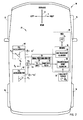
- FIG. 1 is a block diagram of a vehicle equipped with a vehicle crash sensing system for detecting side impact crash and vehicle rollover crash events according to one embodiment of the present invention;
- FIG. 2 is a block diagram of a vehicle equipped with a vehicle crash sensing system for detecting side impact crash and vehicle rollover crash events according to a second embodiment of the present invention;
- FIG. 3 is a flow diagram illustrating a side crash event algorithm according to one embodiment; and
- FIG. 4 is a flow diagram illustrating a rollover crash event algorithm according to one embodiment.
- Referring to FIG. 1, a
vehicle 10 is generally illustrated equipped with a vehiclecrash sensing system 20 for detecting either or both of an impact crash event and a rollover event of thevehicle 10. Thevehicle 10 shown is a wheeled automotive vehicle generally shown having fourwheels crash sensing system 20 may be contained in a module on theautomotive vehicle 10 or may have components at various locations onboard thevehicle 10. Thecrash sensing system 20 has inertial sensors arranged to detect a side crash event along the lateral Y-axis of thevehicle 10 and a rollover crash event about the longitudinal X-axis of thevehicle 10, according to the embodiments shown. However, the vehiclecrash sensing system 20 may be configured with sensors arranged to detect linear crash events and rollover events about any desired axes. - A vehicle rollover event, as explained herein in connection with the present invention, may include side-to-side rotation of the
vehicle 10 about the longitudinal axis, shown as the X-axis, of thevehicle 10, commonly referred to as "vehicle rollover," or back-to-front rotation of thevehicle 10 about the vehicle lateral axis, shown as the Y-axis, commonly referred to as a "vehicle pitchover," or a combination of rollover and pitchover. For purposes of describing the rollover event sensing of the present invention, the term "rollover" is generally used to refer to either a rollover event or a pitchover event. Additionally, an impact crash event may include a side impact crash event of thevehicle 10 along the lateral Y-axis, a frontal or rear impact crash event along the X-axis, or other impact crash events occurring along other sensing axes. - The vehicle
crash sensing system 20 is designed to be located on thevehicle 10 to sense vehicle dynamics, particularly linear acceleration in a direction along a first sensing axis, and an angular rate (velocity) of thevehicle 10 about a second sensing axis. In the embodiments shown and described herein, the first sensing axis (e.g., Y-axis) is orthogonal to the second sensing axis (e.g., X-axis). However, linear acceleration and angular rate may be sensed in other first and second sensing axes according to other embodiments. - Included in the vehicle
crash sensing system 20, according to the first embodiment, is alinear accelerometer 22, shown oriented on thevehicle 10 to sense linear acceleration AY along the lateral Y-axis. One example of a suitable linear accelerometer is Model No. ADXL78 commercially available from Analog Devices, Inc., rated at 50 g. Also included in vehiclecrash sensing system 20 is an angularroll rate sensor 32 arranged, according to the first embodiment, on thevehicle 10 to sense angular roll rate about the longitudinal X-axis of thevehicle 10. One example of a suitable angular rate sensor is Model No. EWTZGC250, commercially available from Panasonic. Thelinear accelerometer 22 and angularroll rate sensor 32 may be located at any of a number of locations on thevehicle 10 to sense linear acceleration along the lateral Y-axis and angular rate about the longitudinal X-axis, respectively. According to some examples, thelinear accelerometer 22 may be mounted in the vehicle passenger compartment, in a vehicle door or on a structural support of thevehicle 10, such as the A-pillar, B-pillar or C-pillar. The angularroll rate sensor 32 may be mounted in the vehicle passenger compartment near the center, according to one example, or elsewhere onboard thevehicle 10. - The
liner accelerometer 22 and angularroll rate sensor 32 are integrated into a single vehiclecrash sensing system 20 to sense either or both of a side impact crash event and a rollover event according to the embodiment shown and described herein. The vehiclecrash sensing system 20 employs thelinear accelerometer 22 to generate a linear acceleration AY that is employed both by a sidecrash event algorithm 50 and a rollovercrash event algorithm 70. The vehiclecrash sensing system 20 therefore employs thelinear accelerometer 20 in a manner that allows for sensing multiple crash events, thereby eliminating the need for separate and distinct acceleration sensors. - The vehicle
crash sensing system 20 has a controller, shown as a microprocessor control unit (MCU) 25, having amicroprocessor 24 andmemory 34. Stored withinmemory 34 are the sidecrash event algorithm 50 and rollovercrash event algorithm 70. Themicroprocessor 24 may include any known analog and/or digital processing circuitry capable of executing the sidecrash event algorithm 50 and rollovercrash event algorithm 70.Memory 34 may include conventional memory storage medium such as electrically erasable programmable read-only memory (EEPROM) or random access memory (RAM) that may store various program calibrations and routines for performing the crash sensing detection. TheMCU 25 may be a dedicated crash sensing controller or may be implemented on a shared controller. - The vehicle
crash sensing system 20 senses a linear impact crash event, such as a side crash event, by processing the linear acceleration signal AY output from thelinear accelerometer 22. For a side impact event, thelinear accelerometer 22 is oriented along the lateral Y-axis of thevehicle 10. The output of thelinear accelerometer 22 is shown input to the sidecrash event algorithm 50. Any of a number of sidecrash event algorithms 50 may be employed to sense the presence of a side impact crash event. One example of a sidecrash event algorithm 50 is shown in FIG. 3. - The
crash sensing system 20 employssignal conditioning circuitry 26 for processing the sensed acceleration signal AY output from thelinear accelerometer 22 and outputs a processed linear acceleration signal to the rollovercrash event algorithm 70. Thesignal conditioning circuitry 26 enables the use of asingle accelerometer 22 that is generally configured for use to detect a side impact crash event to also be employed to detect a vehicle rollover crash event, according to one embodiment of the present invention. Thesignal conditioning circuitry 26 processes the linear acceleration signal output to alter the range, resolution and/or bandwidth of the inertiallinear acceleration sensor 22 used for the side impact crash event in order to provide linear acceleration data that meets the requirements for sensing a second crash-type event, namely a vehicle rollover event. Thesignal conditioning circuitry 26 therefore allows for elimination of duplicative sensors by generating the appropriately processed linear acceleration signal. - The
signal conditioning circuitry 26 is shown including anamplifier 28 coupled to the output oflinear accelerometer 22, and a band-pass filter 26 coupled to the output of theamplifier 28. Theamplifier 28 amplifies the sensed linear acceleration signal AY by an amplification gain, such as 10X according to one example. The band-pass filter 30 has a pass band, such as a frequency range of 0.1 Hz to 50 Hz, according to one embodiment. According to another embodiment, the band-pass filter 30 may have the low frequency portion of the signal removed by the subtraction of the output of a linear integration function tracking the low band portion of the signal. The band-pass filter 30 therefore filters low frequencies below 0.1 Hz and high frequencies above 50 Hz, according to this embodiment, to reduce or eliminate noise. The amplified and filtered linear acceleration signal is then input to the rollovercrash event algorithm 70. - The digital
signal conditioning circuitry 26 may be implemented in analog circuitry, according to one embodiment. According to another embodiment, thesignal conditioning circuitry 26 may be implemented in digital circuitry. According to other embodiments, a combination of analog and digital circuitry may be employed in thesignal conditioning circuitry 26 to process the sensed linear acceleration signal AY and make the processed linear acceleration signal available as an input to the rollovercrash event algorithm 70. - The vehicle
crash sensing system 20 further includes an angularroll rate sensor 32 for sensing angular rate (velocity) φ̇ x of thevehicle 10 about a second sensing axis. In the embodiment shown, the angularroll rate sensor 32 is oriented to sense angular rate about the longitudinal X-axis of thevehicle 10, and generates a sensed angular rate signal φ̇ x indicative thereof. Any of a number ofangular rate sensors 32 may be employed to sense the vehicle angular roll rate φ̇ x. Angularroll rate sensor 32 may be oriented about another sensing axis, such as the lateral Y-axis to determine a pitch rate of thevehicle 10. - The rollover
crash event algorithm 34 therefore receives as inputs the processed linear acceleration signal and the sensed angular roll rate signal. The rollovercrash event algorithm 70 processes the linear acceleration and angular rate signals and determines an anticipated or actual rollover of thevehicle 10 about the longitudinal X-axis. According to other embodiments, the rollovercrash event algorithm 70 may determine a rollover event of thevehicle 10 about other axes, such as the lateral Y-axis, also referred to as a pitchover event. Any of a number of rollover crash event algorithms may be employed. One example of a rollovercrash event algorithm 70 is shown in FIG. 4. - Referring to FIG. 2, a
vehicle 10 is illustrated employing a vehiclecrash sensing system 20 according to a second embodiment of the present invention. The vehiclecrash sensing system 20 according to the second invention employs first and second linear acceleration sensors (accelerometers) 40 and 42, each oriented at an angle offset from each other and in a direction offset from both the longitudinal X-axis and lateral Y-axis of thevehicle 10. The firstlinear accelerometer 40 is oriented in a first axis at an angle θ offset by -45° from the longitudinal X-axis of thevehicle 10 as shown.Linear accelerometer 40 generates a first linear acceleration signal A1 at angle θ = -45°. The secondlinear accelerometer 42 is oriented in a second axis at an angle θ offset by +45° from the longitudinal X-axis of thevehicle 10. The secondlinear accelerometer 42 generates a second linear acceleration signal A2 at angle θ = +45°. Thus, in the embodiment shown, first and secondlinear accelerometers vehicle 10 such that each ofaccelerometers vehicle 10. - It should be appreciated that the first and second
linear accelerometers system 20 according to the second embodiment advantageously sense linear accelerations A1 and A2 about the two separate axes. By orienting the first and secondlinear accelerometers vehicle 10, each of thelinear accelerometer sensors accelerometers - The vehicle
crash sensing system 20 according to the second embodiment employssignal processing circuitry 26 that includes anarithmetic logic device 44, such as a summer or a subtractor for either summing or subtracting the sensed linear acceleration signals A1 and A2 output from the first and secondlinear accelerometers linear accelerometers crash event algorithm 50 for processing as discussed above. - The
signal processing circuitry 26 in the vehiclecrash sensing system 10 according to the second embodiment further employs anamplifier 28 for amplifying arithmetic summed linear acceleration signal, and a band-pass filter 30 for filtering amplified linear acceleration signals. The amplified and filtered linear acceleration signal is then input to a rollovercrash event algorithm 70. Additionally, an angular roll rate signal φ̇ X sensed by angularroll rate sensor 32 oriented to sense angular acceleration about the longitudinal X-axis is also input to the rollovercrash events algorithm 70 and is processed as discussed above in connection with the first embodiment. - The vehicle
crash sensing system 20 according to the second embodiment is shown employing twolinear accelerometers amplifier 28 is of a different magnitude (e.g., 7X) from that of the first embodiment, due to the magnitude of the summing vector acceleration components AX and AY from the two contributinglinear accelerometers pass filter 30 may have a pass band frequency range from 0.1 Hz to 50 Hz, according to one embodiment. - It should be appreciated that the two
linear accelerometers MCU 25 for additional crash event detection or other purposes. The vehiclecrash sensing system 20 may employ additional sensors that may be processed by the same or different crash algorithms that detect any of a number of crash events of thevehicle 10. - Referring to FIG. 3, one example of a side
crash event algorithm 50 is illustrated. The sidecrash event algorithm 50 begins atstep 52 receiving the sensed lateral acceleration signal and proceeds to calculate a lateral velocity instep 54. The lateral velocity calculation may include performing an integration with a forgetting factor.Algorithm 50 then proceeds to apply the lateral acceleration and lateral velocity signals to a side crash detection logic instep 56. The sidecrash detection logic 56 may include any known logic for establishing thresholds indicative of a lateral impact crash event with thevehicle 10. Thealgorithm 50 then detects a side crash event instep 58. Thealgorithm 50 may be repeatedly executed. - Referring to FIG. 4, one example of a rollover
crash event algorithm 70 is illustrated. The rollovercrash event algorithm 70 begins by receiving the processed lateral acceleration signal instep 72 and receiving the sensed roll rate signal instep 74. A rollangle calculation step 76 calculates a roll angle based on the sensed roll rate and lateral acceleration. This may include integrating the roll rate signal. Next, a rollangle prediction step 78 predicts a roll angle based on the processed lateral acceleration signal, the roll angle calculation, and the sensed roll rate. Instep 80, a rollover crash detection logic detects a rollover event based on the processed lateral acceleration signal, roll angle calculation, roll angle prediction, and sensed roll rate. Thedetection logic 80 may include any known rollover crash event detection logic for detecting a vehicle rollover event.Algorithm 70 then detects a rollover crash event as indicated instep 82.Algorithm 70 may be repeatedly executed to continuously detect a rollover event. - It should be appreciated that the side
crash event algorithm 50 and rollovercrash event algorithm 70 may be processed by the same ordifferent MCU 25 or other analog and/or digital circuitry by executing software code as should be evident to those skilled in the art. TheMCU 25 may be part of a dedicated controller or may be a shared controller within thevehicle 10. Additionally, one or more outputs of theMCU 25 generally provides output signal(s) that may be made available to various restraint devices and other devices that may utilize a crash event indicative signal. - The vehicle
crash sensing system 20 according to the present invention advantageously integrates the use of a linear accelerometer signal in acrash sensing system 20 to enable sensing of multiple crash events. In particular, a linear accelerometer is employed to sense a crash event and a rollover event of a vehicle by employing signal processing circuitry so as to eliminate the need for separate and distinct acceleration sensors, thereby eliminating duplication and reducing the cost of the overallcrash sensing system 20. - It will be understood by those who practice the invention and those skilled in the art, that various modifications and improvements may be made to the invention without departing from the spirit of the disclosed concept. The scope of protection afforded is to be determined by the claims and by the breadth of interpretation allowed by law.
Claims (18)
- An integrated vehicle crash sensing system (20) comprising:a linear acceleration sensor (22) located on a vehicle (10) for sensing linear acceleration (AY) along a first sensing axis (Y) and generating a linear acceleration signal;crash sensing logic (50) for determining a crash event along the first sensing axis (Y) as a function of the sensed linear acceleration signal;signal processing circuitry (26) for processing the linear acceleration signal and generating a processed linear acceleration signal;an angular rate sensor (32) located on the vehicle (10) for sensing an angular roll rate (φ̇ x) of the vehicle (1) about a second sensing axis (X) and generating a roll rate signal; androllover crash sensing logic (70) for determining a rollover event of the vehicle (10) about the second sensing axis (X) as a function of the processed linear acceleration signal and the angular roll rate signal.
- The crash sensing system as defined in claim 1, wherein the signal processing circuitry (26) comprises an amplifier (28) for amplifying the sensed linear acceleration signal to generate the processed linear acceleration signal.
- The crash sensing system as defined in claim 2, wherein the signal processing circuitry (26) further comprises a filter (30) for filtering the amplified linear acceleration signal.
- The crash sensing system as defined in claim 3, wherein the filter (30) comprises a band-pass filter.
- The crash sensing system as defined in claim 4, wherein the band-pass filter (30) has a pass band frequency ranging from about 0.1 Hz to 50 Hz.
- The crash sensing system as defined in claim 1, wherein the signal processing circuitry (26) comprises a filter (30) for filtering the sensed acceleration signal.
- The crash sensing system as defined in claim 1, wherein the linear acceleration sensor (22) is oriented to sense linear acceleration along a lateral axis (Y) of the vehicle (10), and the crash sensing logic (50) senses a side impact with the vehicle (10) along the lateral axis (Y) of the vehicle (10).
- The crash sensing system as defined in claim 1, wherein the linear acceleration sensor (22) comprises a first accelerometer (40) oriented to sense linear acceleration (A1) at an angle (θ) offset from both a lateral axis (Y) and a longitudinal axis (X) of the vehicle (10), and a second accelerometer (42) oriented to sense linear acceleration (A2) at an angle offset from the lateral axis (Y) and the longitudinal axis (X) of the vehicle (10), wherein the first and second accelerometers (40, 42) each sense acceleration components (AX, AY) along both the longitudinal axis (X) and the lateral axis (Y) of the vehicle (10).
- The crash sensing system as defined in claim 8, wherein the signal processing circuitry (26) further comprises arithmetic logic (44) for performing one of summing and subtracting the outputs of the first and second accelerometers (40, 42).
- A method of detecting a crash event of a vehicle (10) due to at least one of an impact crash event and a rollover event of the vehicle (10), said method comprising the steps of:sensing linear acceleration (AY) along a first sensing axis (Y) of the vehicle (10) with a linear acceleration sensor (22) and generating a sensed linear acceleration signal;sensing a crash event along the first sensing axis (Y) as a function of the sensed linear acceleration (AY);processing the sensed linear acceleration signal with signal processing circuitry (26) to generate a processed linear acceleration signal;sensing an angular roll rate (φ̇ x) of the vehicle (10) about a second sensing axis (X) and generating a roll rate signal; anddetermining a rollover event of the vehicle (10) about the second sensing axis (X) as a function of the processed linear acceleration signal and the roll rate signal.
- The method as defined in claim 10, wherein the step of sensing linear acceleration comprises sensing linear acceleration along a lateral axis (Y) of the vehicle (10), and the step of sensing a crash event along the first sensing axis (Y) comprises sensing a side impact crash event of the vehicle (10) along the lateral axis (Y) of the vehicle (10).
- The method as defined in claim 8, wherein the step of sensing linear acceleration comprises sensing a first linear acceleration (A1) with a first accelerometer (40) oriented at an angle (θ) offset from a longitudinal axis (X) and a lateral axis (Y) of the vehicle (10) and sensing a second linear acceleration (A2) with a second accelerometer (42) oriented at an angle (θ) offset from the longitudinal axis (X) and the lateral axis (Y) of the vehicle (10), wherein the first and second accelerations (A1, A2) each comprise components (Ax, AY) of linear acceleration in both the lateral axis (Y) and the longitudinal axis (X).
- The method as defined in claim 12 further comprising the step of arithmetically summing or subtracting the first and second acceleration signals to generate a signal indicative of the linear acceleration sensed along the first sensing axis (Y).
- The method as defined in claim 13, wherein the step of filtering comprises filtering signals outside of a pass band in the range of about 0.1 to 50 Hz.
- The method as defined in claim 10, wherein the step of processing the sensed linear acceleration signal comprises the step of filtering the sensed linear acceleration signal.
- The method as defined in claim 10, wherein the step of sensing linear acceleration comprises sensing linear acceleration along a lateral axis of the vehicle, and the step of sensing a crash event along the first sensing axis comprises sensing a side impact crash event of the vehicle along the lateral axis of the vehicle.
- The method as defined in claim 8, wherein the step of sensing linear acceleration comprises sensing a first linear acceleration with a first accelerometer oriented at an angle offset from a longitudinal axis and a lateral axis of the vehicle and sensing a second linear acceleration with a second accelerometer oriented at an angle offset from the longitudinal axis and the lateral axis of the vehicle, wherein the first and second accelerations each comprise components of linear acceleration in both the lateral axis and the longitudinal axis.
- The method as defined in claim 17 further comprising the step of arithmetically summing or subtracting the first and second acceleration signals to generate a signal indicative of the linear acceleration sensed along the first sensing axis.
Applications Claiming Priority (1)
| Application Number | Priority Date | Filing Date | Title |
|---|---|---|---|
| US11/478,347 US7805231B2 (en) | 2006-06-29 | 2006-06-29 | Integrated vehicle crash sensing system and method |
Publications (1)
| Publication Number | Publication Date |
|---|---|
| EP1873020A1 true EP1873020A1 (en) | 2008-01-02 |
Family
ID=38566124
Family Applications (1)
| Application Number | Title | Priority Date | Filing Date |
|---|---|---|---|
| EP07075521A Withdrawn EP1873020A1 (en) | 2006-06-29 | 2007-06-26 | Integrated vehicle crash sensing system and method |
Country Status (2)
| Country | Link |
|---|---|
| US (1) | US7805231B2 (en) |
| EP (1) | EP1873020A1 (en) |
Cited By (3)
| Publication number | Priority date | Publication date | Assignee | Title |
|---|---|---|---|---|
| WO2010094363A1 (en) * | 2009-02-20 | 2010-08-26 | Robert Bosch Gmbh | Method and control device for classifying a collision of a vehicle |
| WO2013106516A1 (en) * | 2012-01-10 | 2013-07-18 | Chrysler Group Llc | Method and system for calibrating rollover settings of a vehicle |
| CN109733382A (en) * | 2018-12-19 | 2019-05-10 | 南京航空航天大学 | A kind of car for guarding against side turned over method based on Model Predictive Control |
Families Citing this family (17)
| Publication number | Priority date | Publication date | Assignee | Title |
|---|---|---|---|---|
| US8386130B2 (en) * | 2007-02-07 | 2013-02-26 | Mitsubishi Electric Corporation | Occupant protection device |
| JP5217307B2 (en) * | 2007-09-07 | 2013-06-19 | アイシン精機株式会社 | Vehicle headrest device |
| DE102008043475B4 (en) * | 2008-11-04 | 2020-06-18 | Robert Bosch Gmbh | Device control method and device control device |
| US9406222B2 (en) | 2012-10-18 | 2016-08-02 | Calamp Corp. | Systems and methods for location reporting of detected events in vehicle operation |
| US10107831B2 (en) | 2012-11-21 | 2018-10-23 | Calamp Corp | Systems and methods for efficient characterization of acceleration events |
| US10466269B2 (en) | 2013-02-19 | 2019-11-05 | Calamp Corp. | Systems and methods for low latency 3-axis accelerometer calibration |
| US9644977B2 (en) | 2015-05-22 | 2017-05-09 | Calamp Corp. | Systems and methods for determining vehicle operational status |
| US10214166B2 (en) | 2015-06-11 | 2019-02-26 | Calamp Corp. | Systems and methods for impact detection with noise attenuation of a sensor signal |
| US10055909B2 (en) | 2016-07-08 | 2018-08-21 | Calamp Corp. | Systems and methods for crash determination |
| US10395438B2 (en) | 2016-08-19 | 2019-08-27 | Calamp Corp. | Systems and methods for crash determination with noise filtering |
| US10219117B2 (en) | 2016-10-12 | 2019-02-26 | Calamp Corp. | Systems and methods for radio access interfaces |
| US10473750B2 (en) | 2016-12-08 | 2019-11-12 | Calamp Corp. | Systems and methods for tracking multiple collocated assets |
| US10599421B2 (en) | 2017-07-14 | 2020-03-24 | Calamp Corp. | Systems and methods for failsafe firmware upgrades |
| US20190141156A1 (en) | 2017-11-06 | 2019-05-09 | Calamp Corp. | Systems and Methods for Dynamic Telematics Messaging |
| US11206171B2 (en) | 2017-11-07 | 2021-12-21 | Calamp Corp. | Systems and methods for dynamic device programming |
| US11203289B2 (en) * | 2019-11-21 | 2021-12-21 | Enterprise Electronics Llc | Emergency center high mounted stop lamp (CHMSL) controller |
| US11648900B2 (en) | 2020-07-27 | 2023-05-16 | Robert Bosch Gmbh | Off-zone crash detection using lateral accelerations at different positions in a vehicle |
Citations (7)
| Publication number | Priority date | Publication date | Assignee | Title |
|---|---|---|---|---|
| GB2335521A (en) * | 1998-03-17 | 1999-09-22 | Autoliv Dev | Vehicle roll sensor |
| US20020019719A1 (en) * | 2000-05-22 | 2002-02-14 | Hermann Kueblbeck | Method for generating an activating algorithm for rollover detection for safety-related devices in automotive vehicles |
| EP1219500A2 (en) * | 2000-12-28 | 2002-07-03 | Toyota Jidosha Kabushiki Kaisha | Rollover determining apparatus and methods |
| EP1270337A2 (en) * | 2001-06-28 | 2003-01-02 | Robert Bosch Corporation | A rollover-sensing system for a vehicle and method of operating the same |
| EP1312515A1 (en) * | 2001-11-08 | 2003-05-21 | Delphi Technologies, Inc. | Adaptive rollover detection apparatus and method |
| US20030158633A1 (en) * | 2002-02-15 | 2003-08-21 | Schubert Peter J. | Vehicle rollover detection having variable sensitivity |
| EP1502823A1 (en) * | 2003-07-22 | 2005-02-02 | Toyota Jidosha Kabushiki Kaisha | Roll over detector for a vehicle |
Family Cites Families (34)
| Publication number | Priority date | Publication date | Assignee | Title |
|---|---|---|---|---|
| US5610575A (en) * | 1994-08-25 | 1997-03-11 | Automotive Systems Laboratory, Inc. | Method and system for detecting vehicle roll-over |
| WO1997049578A1 (en) * | 1996-06-24 | 1997-12-31 | Breed Automotive Technology, Inc. | Controller for vehicular safety device |
| US5825284A (en) * | 1996-12-10 | 1998-10-20 | Rollover Operations, Llc | System and method for the detection of vehicle rollover conditions |
| US5835873A (en) * | 1997-02-21 | 1998-11-10 | Breed Automotive Technology, Inc. | Vehicle safety system with safety device controllers |
| US6038495A (en) * | 1998-02-06 | 2000-03-14 | Delco Electronics Corporation | Vehicle rollover sensing using short-term integration |
| US6002974A (en) * | 1998-02-06 | 1999-12-14 | Delco Electronics Corporation | Vehicle rollover sensing using extended kalman filter |
| US6002975A (en) * | 1998-02-06 | 1999-12-14 | Delco Electronics Corporation | Vehicle rollover sensing |
| US6182783B1 (en) * | 1998-07-23 | 2001-02-06 | Trw Vehicle Safety Systems Inc. | System for protecting a vehicle occupant during a vehicle rollover condition |
| US6212455B1 (en) * | 1998-12-03 | 2001-04-03 | Indiana Mills & Manufacturing, Inc. | Roll sensor system for a vehicle |
| US6301536B1 (en) * | 1999-11-18 | 2001-10-09 | Visteon Global Technologies, Inc. | Method and apparatus for detecting a vehicle rollover |
| DE10010633A1 (en) * | 2000-03-03 | 2001-09-06 | Siemens Ag | Procedure for recognizing a rollover situation |
| US6542792B2 (en) * | 2000-11-29 | 2003-04-01 | Delphi Technologies, Inc. | Vehicle rollover detection apparatus and method |
| JP3788286B2 (en) * | 2001-01-19 | 2006-06-21 | トヨタ自動車株式会社 | Control device for occupant protection device |
| US6600985B2 (en) * | 2001-03-26 | 2003-07-29 | Indiana Mills & Manufacturing, Inc. | Roll sensor system for a vehicle |
| US6535800B2 (en) * | 2001-05-29 | 2003-03-18 | Delphi Technologies, Inc. | Vehicle rollover sensing using angular rate sensors |
| JP3608050B2 (en) * | 2001-07-24 | 2005-01-05 | トヨタ自動車株式会社 | Rollover discrimination device |
| US7107136B2 (en) * | 2001-08-29 | 2006-09-12 | Delphi Technologies, Inc. | Vehicle rollover detection and mitigation using rollover index |
| US6631317B2 (en) * | 2001-10-01 | 2003-10-07 | Ford Global Technologies, Inc. | Attitude sensing system for an automotive vehicle |
| JP3818140B2 (en) * | 2001-12-04 | 2006-09-06 | 株式会社デンソー | Vehicle inclination angle detection device for occupant protection |
| US6925413B2 (en) * | 2001-12-14 | 2005-08-02 | Robert Bosch Gmbh | Method and system for detecting a spatial movement state of moving objects |
| US20030120408A1 (en) * | 2001-12-20 | 2003-06-26 | Caruso Christopher Michael | Vehicle occupant restraint deployment safing system |
| AU2003214228A1 (en) * | 2002-03-19 | 2003-10-08 | Automotive Systems Laboratory, Inc. | Vehicle rollover detection system |
| US7245998B2 (en) * | 2003-02-25 | 2007-07-17 | Denso Corporation | Apparatus for detecting rollover of vehicle and apparatus for activating occupant protective device |
| JP4073856B2 (en) * | 2003-10-08 | 2008-04-09 | 三菱電機株式会社 | Rollover judging device for vehicle |
| US7512461B2 (en) * | 2003-11-25 | 2009-03-31 | Delphi Technologies, Inc. | Vehicle rollover sensing using angular accelerometer |
| US7162340B2 (en) * | 2004-01-08 | 2007-01-09 | Delphi Technologies, Inc. | Vehicle rollover detection and method of anticipating vehicle rollover |
| PL364449A1 (en) * | 2004-01-19 | 2005-07-25 | Delphi Technologies, Inc. | Logic circuit designed to detect vehicle roll-overs and the method for detection of roll-overs |
| US20050171672A1 (en) * | 2004-01-29 | 2005-08-04 | Wallner Edward J. | Vehicle rollover detection using dual-axis acceleration sensing |
| US7702441B2 (en) * | 2004-02-23 | 2010-04-20 | Delphi Technologies, Inc. | Safety logic for vehicle rollover detection systems and a method for detecting near rollover situations |
| US7502675B2 (en) * | 2004-04-01 | 2009-03-10 | Delphi Technologies, Inc. | Feedforward control of motor vehicle roll angle |
| ATE393064T1 (en) * | 2004-07-19 | 2008-05-15 | Delphi Tech Inc | A METHOD AND SYSTEM FOR DETECTING A VEHICLE ROLL CONDITION |
| JP2006226762A (en) * | 2005-02-16 | 2006-08-31 | Mitsubishi Electric Corp | Roll over sensing device |
| US7734394B2 (en) * | 2005-04-25 | 2010-06-08 | Robert Bosch Gmbh | System and method for sensing soil-and curb-tripped rollover events |
| FI118930B (en) * | 2005-09-16 | 2008-05-15 | Vti Technologies Oy | Method for micromechanical measurement of acceleration and micromechanical accelerometer |
-
2006
- 2006-06-29 US US11/478,347 patent/US7805231B2/en active Active
-
2007
- 2007-06-26 EP EP07075521A patent/EP1873020A1/en not_active Withdrawn
Patent Citations (7)
| Publication number | Priority date | Publication date | Assignee | Title |
|---|---|---|---|---|
| GB2335521A (en) * | 1998-03-17 | 1999-09-22 | Autoliv Dev | Vehicle roll sensor |
| US20020019719A1 (en) * | 2000-05-22 | 2002-02-14 | Hermann Kueblbeck | Method for generating an activating algorithm for rollover detection for safety-related devices in automotive vehicles |
| EP1219500A2 (en) * | 2000-12-28 | 2002-07-03 | Toyota Jidosha Kabushiki Kaisha | Rollover determining apparatus and methods |
| EP1270337A2 (en) * | 2001-06-28 | 2003-01-02 | Robert Bosch Corporation | A rollover-sensing system for a vehicle and method of operating the same |
| EP1312515A1 (en) * | 2001-11-08 | 2003-05-21 | Delphi Technologies, Inc. | Adaptive rollover detection apparatus and method |
| US20030158633A1 (en) * | 2002-02-15 | 2003-08-21 | Schubert Peter J. | Vehicle rollover detection having variable sensitivity |
| EP1502823A1 (en) * | 2003-07-22 | 2005-02-02 | Toyota Jidosha Kabushiki Kaisha | Roll over detector for a vehicle |
Cited By (5)
| Publication number | Priority date | Publication date | Assignee | Title |
|---|---|---|---|---|
| WO2010094363A1 (en) * | 2009-02-20 | 2010-08-26 | Robert Bosch Gmbh | Method and control device for classifying a collision of a vehicle |
| CN102325672A (en) * | 2009-02-20 | 2012-01-18 | 罗伯特·博世有限公司 | Method and control device for classifying a collision of a vehicle |
| WO2013106516A1 (en) * | 2012-01-10 | 2013-07-18 | Chrysler Group Llc | Method and system for calibrating rollover settings of a vehicle |
| CN109733382A (en) * | 2018-12-19 | 2019-05-10 | 南京航空航天大学 | A kind of car for guarding against side turned over method based on Model Predictive Control |
| CN109733382B (en) * | 2018-12-19 | 2020-07-07 | 南京航空航天大学 | Automobile rollover prevention method based on model predictive control |
Also Published As
| Publication number | Publication date |
|---|---|
| US20080046147A1 (en) | 2008-02-21 |
| US7805231B2 (en) | 2010-09-28 |
Similar Documents
| Publication | Publication Date | Title |
|---|---|---|
| US7805231B2 (en) | Integrated vehicle crash sensing system and method | |
| EP1346883B1 (en) | Vehicle roll angle estimator and method | |
| EP1002709B1 (en) | Vehicle attitude angle estimation using sensed signal blending | |
| US6535800B2 (en) | Vehicle rollover sensing using angular rate sensors | |
| US7484756B2 (en) | Vehicle side impact crash detection for deployment of curtain and side airbags | |
| US6038495A (en) | Vehicle rollover sensing using short-term integration | |
| US6560519B2 (en) | Rollover-sensing system for a vehicle and method of operating the same | |
| JP3608050B2 (en) | Rollover discrimination device | |
| US6694225B2 (en) | Rollover determining apparatus and methods | |
| EP2288895B1 (en) | Method and apparatus for determining a vehicle pitch-over condition | |
| US8244437B2 (en) | Method and system for restraint deployment using lateral kinetic energy | |
| EP1619083B1 (en) | A method and system for detecting vehicle rollover events | |
| EP2398675B1 (en) | Method and apparatus for controlling an actuatable restraint device using a side pressure sensor | |
| EP2965954A1 (en) | Method and apparatus for controlling an actuatable safety device | |
| EP1559616B1 (en) | Vehicle rollover detection using dual-axis acceleration sensing | |
| US7744123B2 (en) | Method and apparatus for controlling an actuatable restraining device using XY side satellite accelerometers | |
| EP1642780B1 (en) | A method and system for detecting a vehicle rollover | |
| US8118130B2 (en) | Method and apparatus for controlling an actuatable restraining device using XY crush-zone satellite accelerometers | |
| US8392070B2 (en) | Method and apparatus for controlling an actuatable safety device |
Legal Events
| Date | Code | Title | Description |
|---|---|---|---|
| PUAI | Public reference made under article 153(3) epc to a published international application that has entered the european phase |
Free format text: ORIGINAL CODE: 0009012 |
|
| AK | Designated contracting states |
Kind code of ref document: A1 Designated state(s): AT BE BG CH CY CZ DE DK EE ES FI FR GB GR HU IE IS IT LI LT LU LV MC MT NL PL PT RO SE SI SK TR |
|
| AX | Request for extension of the european patent |
Extension state: AL BA HR MK YU |
|
| 17P | Request for examination filed |
Effective date: 20080702 |
|
| AKX | Designation fees paid |
Designated state(s): AT BE BG CH CY CZ DE DK EE ES FI FR GB GR HU IE IS IT LI LT LU LV MC MT NL PL PT RO SE SI SK TR |
|
| 17Q | First examination report despatched |
Effective date: 20080902 |
|
| STAA | Information on the status of an ep patent application or granted ep patent |
Free format text: STATUS: THE APPLICATION IS DEEMED TO BE WITHDRAWN |
|
| 18D | Application deemed to be withdrawn |
Effective date: 20091231 |