EP1872985A1 - Mode mechanization system with integrated heater outlet - Google Patents
Mode mechanization system with integrated heater outlet Download PDFInfo
- Publication number
- EP1872985A1 EP1872985A1 EP20070075518 EP07075518A EP1872985A1 EP 1872985 A1 EP1872985 A1 EP 1872985A1 EP 20070075518 EP20070075518 EP 20070075518 EP 07075518 A EP07075518 A EP 07075518A EP 1872985 A1 EP1872985 A1 EP 1872985A1
- Authority
- EP
- European Patent Office
- Prior art keywords
- gear
- vent
- engaging
- valve
- defrost
- Prior art date
- Legal status (The legal status is an assumption and is not a legal conclusion. Google has not performed a legal analysis and makes no representation as to the accuracy of the status listed.)
- Granted
Links
Images



Classifications
-
- B—PERFORMING OPERATIONS; TRANSPORTING
- B60—VEHICLES IN GENERAL
- B60H—ARRANGEMENTS OF HEATING, COOLING, VENTILATING OR OTHER AIR-TREATING DEVICES SPECIALLY ADAPTED FOR PASSENGER OR GOODS SPACES OF VEHICLES
- B60H1/00—Heating, cooling or ventilating devices
- B60H1/00642—Control systems or circuits; Control members or indication devices for heating, cooling or ventilating devices
- B60H1/00814—Control systems or circuits characterised by their output, for controlling particular components of the heating, cooling or ventilating installation
- B60H1/00821—Control systems or circuits characterised by their output, for controlling particular components of the heating, cooling or ventilating installation the components being ventilating, air admitting or air distributing devices
- B60H1/00835—Damper doors, e.g. position control
- B60H1/00857—Damper doors, e.g. position control characterised by the means connecting the initiating means, e.g. control lever, to the damper door
-
- B—PERFORMING OPERATIONS; TRANSPORTING
- B60—VEHICLES IN GENERAL
- B60H—ARRANGEMENTS OF HEATING, COOLING, VENTILATING OR OTHER AIR-TREATING DEVICES SPECIALLY ADAPTED FOR PASSENGER OR GOODS SPACES OF VEHICLES
- B60H1/00—Heating, cooling or ventilating devices
- B60H1/00507—Details, e.g. mounting arrangements, desaeration devices
- B60H1/00514—Details of air conditioning housings
-
- Y—GENERAL TAGGING OF NEW TECHNOLOGICAL DEVELOPMENTS; GENERAL TAGGING OF CROSS-SECTIONAL TECHNOLOGIES SPANNING OVER SEVERAL SECTIONS OF THE IPC; TECHNICAL SUBJECTS COVERED BY FORMER USPC CROSS-REFERENCE ART COLLECTIONS [XRACs] AND DIGESTS
- Y10—TECHNICAL SUBJECTS COVERED BY FORMER USPC
- Y10T—TECHNICAL SUBJECTS COVERED BY FORMER US CLASSIFICATION
- Y10T137/00—Fluid handling
- Y10T137/8593—Systems
- Y10T137/877—With flow control means for branched passages
- Y10T137/87708—With common valve operator
- Y10T137/87732—With gearing
Definitions
- the subject invention relates to an assembly for controlling airflow in an HVAC system in different modes of operation.
- HVAC systems typically include a variety of ducts for conducting air based on a selected mode of operation.
- a vehicle HVAC system might include heater ducts, defrost ducts, and rear mode ducts.
- a housing is provided to house a plurality of valves for directing airflow through these ducts.
- the housing defines a side port outlet in fluid communication with one of the ducts.
- a plurality of driven gears are connected to a plurality of valve levers.
- the levers connect the valves to one of the driven gears for actuating the valves in response to rotation of the driven gears.
- Torque for rotating the driven gears is provided by an actuator (not shown) rotating a drive gear.
- a transmission member is provided to link the drive gear to the driven gears while circumventing the side port.
- the known transmission member comprises a series of levers extending between the gears. These levers provide inefficient torque transmission from the actuator.
- the subject invention provides such a heat exchanger wherein the transmission member includes an annular idling gear rotatably supported on the housing for rotation about an annular gear axis and encircling the side port and engaging the drive gear and engaging the driven gear.
- FIG. 1 is a perspective view of an HVAC control housing in accordance with an exemplary embodiment of the present invention
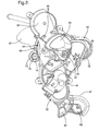
- Figure 2 is a perspective view of a subassembly for actuating the valves of the housing in accordance with the exemplary embodiment
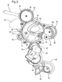
- Figure 3 is a perspective view of the subassembly of Figure 2 with the upper mounting bracket removed;
- Figure 4 is an alternate perspective view of the subassembly of Figure 2 from a rear elevation
- Figure 5 is an exploded perspective view of the subassembly of Figure 2;
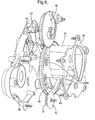
- Figure 6 is a fragmentary view of the subassembly showing the fingers disposed on the upper mounting bracket.
- an assembly 20 is generally shown for controlling airflow in an HVAC system in different modes of operation.
- the assembly 20 includes a housing 22 for directing airflow through a plurality of ducts within the housing 22.
- a housing outlet 24 having an outer periphery is defined on the housing 22 and is connected fluidly to one of the plurality of ducts.
- the housing outlet 24 is connected to a heater duct.
- a plurality of valves 26, 28, 30, 32 extend within the housing 22. Although the exemplary embodiment shows four valves 26, 28, 30, 32, the use of the term plurality throughout the application should be understood to mean two or more.
- the valves 26, 28, 30, 32 are rotatably supported within the housing 22 and direct airflow through at least one of the plurality of ducts in response to a selected mode of operation.
- a side port 34 extends outwardly from the housing 22 and is in fluid communication with the housing outlet 24.
- the housing 22 includes a lower mounting bracket 36 extending laterally outwardly from the side port 34, and is formed integrally with the side port 34.
- the housing 22 also includes an upper mounting bracket 38 having an opening therein for receiving the side port 34.
- a gear system is provided to actuate the plurality of valves 26, 28, 30, 32, including a drive gear 40 rotatably supported on the upper mounting bracket 38 for rotation about a drive axis A.
- the drive gear 40 includes a plurality of drive gear teeth 42 disposed thereabout.
- An actuator 44 is secured to the upper mounting bracket 38 for rotating the drive gear 40 about the drive axis A.
- a plurality of driven gears 46, 48, 50 are also provided.
- the plurality of driven gears 46, 48, 50 includes a vent driven gear 46, a defrost driven gear 48, and a rear mode driven gear 50.
- Each driven gear is rotatably supported on the upper mounting bracket 38, and is connected to the plurality of valves 26, 28, 30, 32 through a plurality of valve levers 52, 54, 56, 58, 60, 62.
- Each valve lever connects one of the valves 26, 28, 30, 32 to one of the driven gears 46, 48, 50 for actuating the valves 26, 28, 30, 32 in response to rotation of the driven gears 46, 48, 50.
- the respective valve lever systems for each driven gear will be discussed in more detail later.
- the gear system includes a transmission member supported on the upper mounting bracket 38 for connecting the drive gear 40 to the driven gears 46, 48, 50 for rotating the driven gears 46, 48, 50 in response to the drive gear 40.
- the transmission member is an annular idling gear 64 having a plurality of annular idling gear teeth 66 for meshing engagement with the drive gear teeth 42.
- the annular idling gear 64 is rotatably supported by the upper mounting bracket 38 and sandwiched between the upper mounting bracket 38 and the lower mounting bracket 36 and encircles the side port 34.
- the upper mounting bracket 38 includes a plurality of fingers 68 for securing the annular idling gear 64 between the upper and lower mounting brackets 38, 36.
- a positioning gear 70 is rotatably supported on the lower mounting bracket 36 and includes a plurality of positioning gear teeth 72 in meshing engagement with the annular idling gear 64 for securing the annular idling gear 64 laterally about the side port 34.
- the positioning gear 70 includes a positioning gear flange 74 extending outwardly in a radial fashion. The flange extends between the annular idling gear 64 and the lower mounting bracket 36 to space the annular idling gear 64 from the lower mounting bracket 36.
- Each of the vent driven gear 46 and defrost driven gear 48 also includes a plurality of meshing gear teeth, including vent driven gear teeth 76 and defrost driven gear teeth 78, respectively, for meshing engagement with the annular idling gear teeth 66.
- the vent driven gear 46 and defrost driven gear 48 also each include a vent driven gear flange 80 and a defrost driven gear flange 82 extending outwardly in a radial fashion to space the annular idling gear 64 from the lower mounting bracket 36.
- the rear mode driven gear 50 includes a plurality of rear mode driven gear 50 teeth for meshing engagement with the drive gear teeth 42.
- the plurality of valves 26, 28, 30, 32 includes a slice valve 26 covering the outer periphery of the housing outlet 24 when in a closed position.
- the slice valve 26 includes a corresponding slice valve 26 for covering a corresponding housing outlet 24 on the opposite end of the housing 22.
- the slice valve 26 is rotatable about a slice valve axis B to an open position to fluidly connect the housing outlet 24 to the heater duct (not shown).
- the plurality of valve levers 52, 54, 56, 58, 60, 62 includes a first heater lever 52 engaging the slice valve 26, and a second heater lever 54 engaging the first heater lever 52.
- the plurality of valves 26, 28, 30, 32 also includes a vent flap valve 28 rotatable about the slice valve axis B for selectively directing airflow to at least one of a dashboard outlet (not shown) and a floorboard outlet (not shown).
- the plurality of valve levers 52, 54, 56, 58, 60, 62 includes a vent lever 56 engaging the vent flap valve 28.
- the vent driven gear 46 includes oppositely facing sides to define a vent side and a heater side.
- a vent cam track 84 is disposed along the vent side, engaging the vent lever 56 for operating the vent flap valve 28 in response to the vent driven gear 46.
- a heater cam track 86 is disposed along the heater side, engaging the second heater lever 54 for operating the slice valve 26 in response to the vent driven gear 46.
- the plurality of valves 26, 28, 30, 32 includes a defrost flap valve 30 for selectively directing airflow to a defrost outlet (not shown), and the plurality of valve levers 52, 54, 56, 58, 60, 62 includes a defrost valve lever 58 engaging the defrost flap valve 30.
- the defrost driven gear 48 includes a defrost cam track 88 engaging the defrost lever for operating the defrost flap valve 30 in response to the defrost driven gear 48.
- the plurality of valves 26, 28, 30, 32 includes a rear mode flap valve 32 for selectively directing airflow to a rear outlet (not shown), and the plurality of valve levers 52, 54, 56, 58, 60, 62 includes a first rear mode lever 60 engaging the rear mode flap valve 32 and a second rear mode lever 62 engaging the first rear mode lever 60 .
- the rear mode driven gear 50 includes a rear mode cam track 90 engaging the second rear mode lever 62 for operating the rear mode flap valve 32 in response to the rear mode driven gear 50.
- each of the cam tracks 84, 86, 88, 90 follows a non-linear path so that rotation of the actuator 44 to the same radial position will not always position the valves 26, 28, 30, 32 in the same manner.
- the actuator 44 then provides torque to rotate the drive gear 40, which is, in turn, threadingly engaged with the annular idling gear 64.
- the annular idling gear 64 is threadingly engaged with both the defrost driven gear 48 and the vent driven gear 46.
- the drive gear 40 is also threadingly engaged with the rear mode driven gear 50. Based on a selected mode of operation, the actuator 44 rotates to a specified position that causes each of the driven gears 46, 48, 50 to rotate in response.
- the levers 52, 54, 56, 58, 60, 62 translate along the cam tracks 84, 86, 88, 90 inducing a rotation in the respective valves 26, 28, 30, 32 about a fixed point, thereby causing air to be ducted through the HVAC system in accordance with the selected mode of operation.
Landscapes
- Physics & Mathematics (AREA)
- Thermal Sciences (AREA)
- Engineering & Computer Science (AREA)
- Mechanical Engineering (AREA)
- Air-Conditioning For Vehicles (AREA)
- Mechanically-Actuated Valves (AREA)
- General Details Of Gearings (AREA)
- Gear Transmission (AREA)
- Massaging Devices (AREA)
- Air-Flow Control Members (AREA)
- Multiple-Way Valves (AREA)
Abstract
Description
- The subject invention relates to an assembly for controlling airflow in an HVAC system in different modes of operation.
- HVAC systems typically include a variety of ducts for conducting air based on a selected mode of operation. For example, a vehicle HVAC system might include heater ducts, defrost ducts, and rear mode ducts. A housing is provided to house a plurality of valves for directing airflow through these ducts. The housing defines a side port outlet in fluid communication with one of the ducts. A plurality of driven gears are connected to a plurality of valve levers. The levers connect the valves to one of the driven gears for actuating the valves in response to rotation of the driven gears. Torque for rotating the driven gears is provided by an actuator (not shown) rotating a drive gear. A transmission member is provided to link the drive gear to the driven gears while circumventing the side port. The known transmission member comprises a series of levers extending between the gears. These levers provide inefficient torque transmission from the actuator.
- The subject invention provides such a heat exchanger wherein the transmission member includes an annular idling gear rotatably supported on the housing for rotation about an annular gear axis and encircling the side port and engaging the drive gear and engaging the driven gear.
- Other advantages of the present invention will be readily appreciated, as the same becomes better understood by reference to the following detailed description when considered in connection with the accompanying drawings wherein:
- Figure 1 is a perspective view of an HVAC control housing in accordance with an exemplary embodiment of the present invention;
- Figure 2 is a perspective view of a subassembly for actuating the valves of the housing in accordance with the exemplary embodiment;
- Figure 3 is a perspective view of the subassembly of Figure 2 with the upper mounting bracket removed;
- Figure 4 is an alternate perspective view of the subassembly of Figure 2 from a rear elevation;
- Figure 5 is an exploded perspective view of the subassembly of Figure 2;
- Figure 6 is a fragmentary view of the subassembly showing the fingers disposed on the upper mounting bracket.
- Referring to the Figures, wherein like numerals indicate corresponding parts throughout the several views, an
assembly 20 is generally shown for controlling airflow in an HVAC system in different modes of operation. Referring first to Figure 1, theassembly 20 includes ahousing 22 for directing airflow through a plurality of ducts within thehousing 22. Ahousing outlet 24 having an outer periphery is defined on thehousing 22 and is connected fluidly to one of the plurality of ducts. According to the exemplary embodiment, thehousing outlet 24 is connected to a heater duct. Referring next to Figures 2-5, a plurality ofvalves housing 22. Although the exemplary embodiment shows fourvalves valves housing 22 and direct airflow through at least one of the plurality of ducts in response to a selected mode of operation. - A
side port 34 extends outwardly from thehousing 22 and is in fluid communication with thehousing outlet 24. Thehousing 22 includes alower mounting bracket 36 extending laterally outwardly from theside port 34, and is formed integrally with theside port 34. Thehousing 22 also includes anupper mounting bracket 38 having an opening therein for receiving theside port 34. - A gear system is provided to actuate the plurality of
valves drive gear 40 rotatably supported on theupper mounting bracket 38 for rotation about a drive axis A. Thedrive gear 40 includes a plurality ofdrive gear teeth 42 disposed thereabout. Anactuator 44 is secured to theupper mounting bracket 38 for rotating thedrive gear 40 about the drive axis A. A plurality of drivengears gears gear 46, a defrost drivengear 48, and a rear mode drivengear 50. Each driven gear is rotatably supported on theupper mounting bracket 38, and is connected to the plurality ofvalves valve levers valves gears valves gears - The gear system includes a transmission member supported on the
upper mounting bracket 38 for connecting thedrive gear 40 to the drivengears gears drive gear 40. According to the exemplary embodiment, the transmission member is an annularidling gear 64 having a plurality of annularidling gear teeth 66 for meshing engagement with thedrive gear teeth 42. The annularidling gear 64 is rotatably supported by theupper mounting bracket 38 and sandwiched between theupper mounting bracket 38 and thelower mounting bracket 36 and encircles theside port 34. As shown more clearly in Figure 6, theupper mounting bracket 38 includes a plurality offingers 68 for securing the annularidling gear 64 between the upper andlower mounting brackets positioning gear 70 is rotatably supported on thelower mounting bracket 36 and includes a plurality ofpositioning gear teeth 72 in meshing engagement with the annularidling gear 64 for securing the annularidling gear 64 laterally about theside port 34. Thepositioning gear 70 includes apositioning gear flange 74 extending outwardly in a radial fashion. The flange extends between the annularidling gear 64 and thelower mounting bracket 36 to space the annularidling gear 64 from thelower mounting bracket 36. Each of the vent drivengear 46 and defrost drivengear 48 also includes a plurality of meshing gear teeth, including vent drivengear teeth 76 and defrost drivengear teeth 78, respectively, for meshing engagement with the annularidling gear teeth 66. The vent drivengear 46 and defrost drivengear 48 also each include a vent drivengear flange 80 and a defrost drivengear flange 82 extending outwardly in a radial fashion to space the annularidling gear 64 from thelower mounting bracket 36. The rear mode drivengear 50 includes a plurality of rear mode drivengear 50 teeth for meshing engagement with thedrive gear teeth 42. - According to a first aspect of the exemplary embodiment, the plurality of
valves slice valve 26 covering the outer periphery of thehousing outlet 24 when in a closed position. As can be seen more easily in Figure 4, theslice valve 26 includes acorresponding slice valve 26 for covering acorresponding housing outlet 24 on the opposite end of thehousing 22. Theslice valve 26 is rotatable about a slice valve axis B to an open position to fluidly connect thehousing outlet 24 to the heater duct (not shown). The plurality of valve levers 52, 54, 56, 58, 60, 62 includes afirst heater lever 52 engaging theslice valve 26, and asecond heater lever 54 engaging thefirst heater lever 52. The plurality ofvalves vent flap valve 28 rotatable about the slice valve axis B for selectively directing airflow to at least one of a dashboard outlet (not shown) and a floorboard outlet (not shown). The plurality of valve levers 52, 54, 56, 58, 60, 62 includes avent lever 56 engaging thevent flap valve 28. The vent drivengear 46 includes oppositely facing sides to define a vent side and a heater side. Avent cam track 84 is disposed along the vent side, engaging thevent lever 56 for operating thevent flap valve 28 in response to the vent drivengear 46. Aheater cam track 86 is disposed along the heater side, engaging thesecond heater lever 54 for operating theslice valve 26 in response to the vent drivengear 46. - According to a second aspect of the exemplary embodiment, the plurality of
valves defrost flap valve 30 for selectively directing airflow to a defrost outlet (not shown), and the plurality ofvalve levers defrost valve lever 58 engaging thedefrost flap valve 30. The defrost drivengear 48 includes adefrost cam track 88 engaging the defrost lever for operating thedefrost flap valve 30 in response to the defrost drivengear 48. - According to a third aspect of the exemplary embodiment, the plurality of
valves mode flap valve 32 for selectively directing airflow to a rear outlet (not shown), and the plurality ofvalve levers rear mode lever 60 engaging the rearmode flap valve 32 and a secondrear mode lever 62 engaging the firstrear mode lever 60. The rear mode drivengear 50 includes a rearmode cam track 90 engaging the secondrear mode lever 62 for operating the rearmode flap valve 32 in response to the rear mode drivengear 50. - According to the exemplary embodiment, each of the cam tracks 84, 86, 88, 90 follows a non-linear path so that rotation of the
actuator 44 to the same radial position will not always position thevalves actuator 44 then provides torque to rotate thedrive gear 40, which is, in turn, threadingly engaged with theannular idling gear 64. Theannular idling gear 64 is threadingly engaged with both the defrost drivengear 48 and the vent drivengear 46. Thedrive gear 40 is also threadingly engaged with the rear mode drivengear 50. Based on a selected mode of operation, theactuator 44 rotates to a specified position that causes each of the driven gears 46, 48, 50 to rotate in response. Thelevers respective valves - While the invention has been described with reference to an exemplary embodiment, it will be understood by those skilled in the art that various changes may be made and equivalents may be substituted for elements thereof without departing from the scope of the invention. In addition, many modifications may be made to adapt a particular situation or material to the teachings of the invention without departing from the essential scope thereof. Therefore, it is intended that the invention not be limited to the particular embodiment disclosed as the best mode contemplated for carrying out this invention, but that the invention will include all embodiments falling within the scope of the appended claims.
Claims (23)
- An assembly (20) for controlling airflow in an HVAC system in different modes of operation comprising;
a housing (22) defining a housing outlet (24),
at least one valve extending within said housing (22) for directing airflow through at least one of a plurality of ducts
a side port (34) extending outwardly from said housing (22) in fluid communication with said housing outlet (24),
a drive gear (40) rotatably supported on said housing (22) for rotation about a drive axis (A),
at least one driven gear rotatably supported on said housing (22) and engaging said valve for actuating said valve,
a transmission member for connecting said drive gear (40) to said driven gear for rotating said driven gear in response to said drive gear (40),
said transmission member including an annular idling gear (64) rotatably supported on said housing (22) for rotation about an annular gear axis and encircling said side port (34) and engaging said drive gear (40) and engaging said driven gear. - An assembly (20) as set forth in claim 1 wherein said housing (22) includes an upper mounting bracket (38) having an opening therein for receiving said side port (34) and rotatably supporting and securing said annular gear axially.
- An assembly (20) as set forth in claim 2 wherein said driven gear includes a driven gear flange extending radially outwardly therefrom and extending beneath said annular idling gear (64) for spacing said annular idling gear (64) axially from said housing (22).
- An assembly (20) as set forth in claim 3 wherein said upper mounting bracket (38) includes at least one finger (68) for securing said annular idling gear (64) axially against said driven gear flange.
- An assembly (20) as set forth in claim 2 including a positioning gear (70) engaging said annular idling gear (64) for securing said annular idling gear (64) laterally about said side port (34).
- An assembly (20) as set forth in claim 5 wherein said positioning gear (70) includes a positioning gear flange (74) extending radially outwardly therefrom and extending beneath said annular idling gear (64) for spacing said annular idling gear (64) axially from said housing (22).
- An assembly (20) as set forth in claim 2 wherein said housing (22) includes a lower mounting bracket (36) extending between said annular idling gear (64) and said housing (22) and spaced axially from said annular idling gear (64) by said driven gear flange.
- An assembly (20) as set forth in claim 7 wherein said lower mounting bracket (36) extends laterally outwardly from said side port (34).
- An assembly (20) as set forth in claim 2 including a plurality of valves (26, 28, 30, 32) extending within said housing (22) and rotatably supported therein for directing airflow through at least one of a plurality of ducts in response to a selected mode of operation.
- An assembly (20) as set forth in claim 9 including a plurality of said driven gears (46, 48, 50) each rotatably supported on said upper mounting bracket (38).
- An assembly (20) as set forth in claim 10 including a plurality of valve levers (52, 54, 56, 58, 60, 62) each connecting one of said valves (26, 28, 30, 32) to one of said driven gears (46, 48, 50) for actuating said valves (26, 28, 30, 32) in response to rotation of said driven gears (46, 48, 50).
- An assembly (20) as set forth in claim 11 wherein said plurality of driven gears (46, 48, 50) each include at least one cam track engaging at least one of said plurality of valve levers (52, 54, 56, 58, 60, 62) for operating at least one of said valves (26, 28, 30, 32) in response to said driven gear.
- An assembly (20) as set forth in claim 12 wherein said plurality of valves (26, 28, 30, 32) includes a slice valve (26) covering said housing outlet (24) in a closed position and rotatable about a slice valve axis (B) to an open position and said plurality of valve levers (52, 54, 56, 58, 60, 62) including a first heater lever (52) engaging said slice valve (26) and said plurality of valve levers (52, 54, 56, 58, 60, 62) including a second heater lever (54) engaging said first heater lever (52).
- An assembly (20) as set forth in claim 13 wherein said plurality of valves (26, 28, 30, 32) includes a vent flap valve (28) rotatable about said slice valve axis (B) for selectively directing airflow to at least one of a dashboard outlet and a floorboard outlet and said plurality of valve levers (52, 54, 56, 58, 60, 62) includes a vent lever (56) engaging said vent flap valve (28) and said plurality of driven gears (46, 48, 50) includes a vent driven gear (46) having oppositely facing sides to define a vent side and a heater side and rotatable about a vent gear axis engaging said annular idling gear (64) for rotation in response to said drive gear (40).
- An assembly (20) as set forth in claim 14 wherein said vent driven gear (46) includes a vent driven gear flange (80) extending radially outwardly therefrom and extending beneath said annular idling gear (64) for spacing said annular idling gear (64) axially from said housing (22).
- An assembly (20) as set forth in claim 14 wherein said vent driven gear (46) includes a vent cam track (84) along said vent side engaging said vent lever (56) for operating said vent flap valve (28) in response to said vent driven gear (46).
- An assembly (20) as set forth in claim 14 wherein said vent driven gear (46) includes a heater cam track (86) along said heater side engaging said second heater lever (54) for operating said slice valve (26) in response to said vent driven gear (46).
- An assembly (20) as set forth in claim 12 wherein said plurality of valves (26, 28, 30, 32) includes a defrost flap valve (30) for selectively directing airflow to a defrost outlet and said plurality of valve levers (52, 54, 56, 58, 60, 62) includes a defrost valve lever (58) engaging said defrost flap valve (30) and said plurality of driven gears (46, 48, 50) includes a defrost driven gear (48) rotatable about a defrost gear axis engaging said annular idling gear (64) for rotation in response to said drive gear (40) and said defrost driven gear (48) includes a defrost cam track (88) engaging said defrost lever for operating said defrost flap valve (30) in response to said defrost driven gear (48).
- An assembly (20) as set forth in claim 18 wherein said defrost driven gear (48) includes a defrost driven gear flange (82) extending radially outwardly therefrom and extending beneath said annular idling gear (64) for spacing said annular idling gear (64) axially from said housing (22).
- An assembly (20) as set forth in claim 12 wherein said plurality of valves (26, 28, 30, 32) includes a rear mode flap valve (32) for selectively directing airflow to a rear outlet and said plurality of valve levers (52, 54, 56, 58, 60, 62) includes a first rear mode lever (60) engaging said rear mode flap valve (32) and a second rear mode lever (62) engaging said first rear mode lever (60) and said plurality of driven gears (46, 48, 50) includes a rear mode driven gear (50) rotatable about a rear mode axis and engaged directly with said drive gear (40) and said rear mode driven gear (50) includes a rear mode cam track (90) engaging said second rear mode lever (62) for operating said rear mode flap valve (32) in response to said rear mode driven gear (50).
- An assembly (20) as set forth in claim 10 wherein said drive gear (40) and said driven gears (46, 48, 50) each include a plurality of meshing gear teeth for respective meshing engagement with each other.
- An assembly (20) as set forth in claim 2 including an actuator (44) secured to said upper mounting bracket (38) for rotating said drive gear (40) about said drive axis (A).
- An assembly (20) for controlling airflow in an HVAC system in different modes of operation comprising;
a housing (22) defining a housing outlet (24) having an outer periphery,
a plurality of valves (26, 28, 30, 32) extending within said housing (22) and rotatably supported therein for directing airflow through at least one of a plurality of ducts in response to a selected mode of operation,
a side port (34) extending outwardly from said housing (22) in fluid communication with said housing outlet (24),
said housing (22) including a lower mounting bracket (36) extending laterally outwardly from said side port (34),
said housing (22) including an upper mounting bracket (38) having an opening therein for receiving said side port (34),
a drive gear (40) including a plurality of drive gear teeth (42) and rotatably supported on said upper mounting bracket (38) for rotation about a drive axis (A),
an actuator (44) secured to said upper mounting bracket (38) for rotating said drive gear (40) about said drive axis (A),
a plurality of driven gears (46, 48, 50) each rotatably supported on said upper mounting bracket (38),
a plurality of valve levers (52, 54, 56, 58, 60, 62) each connecting one of said valves (26, 28, 30, 32) to one of said driven gears (46, 48, 50) for actuating said valves (26, 28, 30, 32) in response to rotation of said driven gears (46, 48, 50),
a transmission member supported on said upper mounting bracket (38) for connecting said drive gear (40) to at least one of said driven gears (46, 48, 50) for rotating at least one of said driven gears (46, 48, 50) in response to said drive gear (40),
said plurality of valves (26, 28, 30, 32) including a slice valve (26) covering said outer periphery of said housing outlet (24) in a closed position and rotatable about a slice valve axis (B) to an open position,
said plurality of valve levers (52, 54, 56, 58, 60, 62) including a first heater lever (52) engaging said slice valve (26),
said plurality of valve levers (52, 54, 56, 58, 60, 62) including a second heater lever (54) engaging said first heater lever (52),
said plurality of valves (26, 28, 30, 32) including a vent flap valve (28) rotatable about said slice valve axis (B) for selectively directing airflow to at least one of a dashboard outlet and a floorboard outlet,
said plurality of valve levers (52, 54, 56, 58, 60, 62) including a vent lever (56) engaging said vent flap valve (28),
said plurality of driven gears (46, 48, 50) including a vent driven gear (46) rotatable about a vent gear axis and including a plurality of vent gear teeth engaging said transmission member for rotation in response to said drive gear (40),
said vent driven gear (46) including oppositely facing sides to define a vent side and a heater side,
said vent driven gear (46) including a vent cam track (84) along said vent side engaging said vent lever (56) for operating said vent flap valve (28) in response to said vent driven gear (46),
said vent driven gear (46) including a heater cam track (86) along said heater side engaging said second heater lever (54) for operating said slice valve (26) in response to said vent driven gear (46),
said plurality of valves (26, 28, 30, 32) including a defrost flap valve (30) for selectively directing airflow to a defrost outlet,
said plurality of valve levers (52, 54, 56, 58, 60, 62) including a defrost valve lever (58) engaging said defrost flap valve (30),
said plurality of driven gears (46, 48, 50) including a defrost driven gear (48) rotatable about a defrost gear axis and including a plurality of defrost gear teeth engaging said transmission member for rotation in response to said drive gear (40),
said defrost driven gear (48) including a defrost cam track (88) engaging said defrost lever for operating said defrost flap valve (30) in response to said defrost driven gear (48),
said plurality of valves (26, 28, 30, 32) including a rear mode flap valve (32) for selectively directing airflow to a rear outlet,
said plurality of valve levers (52, 54, 56, 58, 60, 62) including a first rear mode lever (60) engaging said rear mode flap valve (32),
said plurality of valve levers (52, 54, 56, 58, 60, 62) including a second rear mode lever (62) engaging said first rear mode lever (60),
said plurality of driven gears (46, 48, 50) including a rear mode driven gear (50) rotatable about a rear mode axis and including a plurality of rear mode gear teeth engaging said drive gear teeth (42),
said rear mode driven gear (50) including a rear mode cam track (90) engaging said second rear mode lever (62) for operating said rear mode flap valve (32) in response to said rear mode driven gear (50),
said transmission member including an annular idling gear (64) having annular idling gear teeth (66) engaging said drive gear teeth (42) and rotatable about an annular gear axis,
said annular idling gear (64) rotatably supported by said upper mounting bracket (38) and sandwiched between said upper mounting bracket (38) and said lower mounting bracket (36),
said annular idling gear teeth (66) engaging said vent driven gear teeth (76) and said defrost driven gear teeth (78),
said annular idling gear (64) encircling said side port (34),
a positioning gear (70) including a plurality of positioning gear teeth (72) directly engaging said annular idling gear (64) for securing said annular idling gear (64) laterally about the side port (34),
said positioning gear (70) including a positioning gear flange (74) extending radially outwardly therefrom and extending between said annular idling gear (64) and said lower mounting bracket (36),
said defrost driven gear (48) including a defrost driven gear flange (82) extending radially outwardly therefrom and extending between said annular idling gear (64) and said lower mounting bracket (36),
said vent driven gear (46) including a vent driven gear flange (80) extending radially outwardly therefrom and extending between said annular idling gear (64) and said lower mounting bracket (36), and
said upper mounting bracket (38) including a plurality of fingers (68) for securing said annular idling gear (64) between said upper and lower mounting brackets (38,36)
Applications Claiming Priority (2)
| Application Number | Priority Date | Filing Date | Title |
|---|---|---|---|
| US81765906P | 2006-06-29 | 2006-06-29 | |
| US11/708,482 US7517278B2 (en) | 2006-06-29 | 2007-02-20 | Mode mechanization system with integrated heater outlet |
Publications (2)
| Publication Number | Publication Date |
|---|---|
| EP1872985A1 true EP1872985A1 (en) | 2008-01-02 |
| EP1872985B1 EP1872985B1 (en) | 2009-12-16 |
Family
ID=38535395
Family Applications (1)
| Application Number | Title | Priority Date | Filing Date |
|---|---|---|---|
| EP20070075518 Not-in-force EP1872985B1 (en) | 2006-06-29 | 2007-06-25 | Mode mechanization system with integrated heater outlet |
Country Status (5)
| Country | Link |
|---|---|
| US (1) | US7517278B2 (en) |
| EP (1) | EP1872985B1 (en) |
| JP (1) | JP4856582B2 (en) |
| AT (1) | ATE452037T1 (en) |
| DE (1) | DE602007003779D1 (en) |
Cited By (3)
| Publication number | Priority date | Publication date | Assignee | Title |
|---|---|---|---|---|
| EP2168793A1 (en) * | 2008-09-25 | 2010-03-31 | Behr GmbH & Co. KG | Air conditioning device |
| EP2907682A3 (en) * | 2014-02-13 | 2015-10-07 | Delphi Technologies, Inc. | Combination linear and rotary actuator |
| CN111043683A (en) * | 2020-01-14 | 2020-04-21 | 衢州若楠智能控制系统有限公司 | Air purification device with voice control humidification |
Families Citing this family (13)
| Publication number | Priority date | Publication date | Assignee | Title |
|---|---|---|---|---|
| US20090156343A1 (en) * | 2007-12-14 | 2009-06-18 | Stevenson Mark W | Force multiplying control cable system |
| JP5502409B2 (en) * | 2009-09-25 | 2014-05-28 | 株式会社ケーヒン | Air conditioner for vehicles |
| KR101154265B1 (en) * | 2010-08-26 | 2012-06-13 | 현대자동차주식회사 | Door actuator for hvac of vehicle |
| US20140000397A1 (en) * | 2012-06-29 | 2014-01-02 | Visteon Global Technologies, Inc. | Constant to variable gear pitch for temperature door rotation |
| US9067474B2 (en) * | 2013-03-15 | 2015-06-30 | Denso International America, Inc. | Gear with idle zones |
| FR3004504B1 (en) * | 2013-04-12 | 2015-04-24 | Valeo Sys Controle Moteur Sas | VALVE, IN PARTICULAR ENGINE CONTROL, COMPRISING A DOSING COMPONENT AND A NEEDLE FLAP |
| DE102015112378B4 (en) * | 2015-07-29 | 2023-03-16 | Halla Visteon Climate Control Corp. | System for air distribution of an air conditioning system of a motor vehicle and method for operating the system |
| US10661630B2 (en) * | 2015-10-16 | 2020-05-26 | Hanon Systems | HVAC kinematics to provide temperature and mode control with one actuator |
| DE102017011180B4 (en) * | 2017-12-04 | 2023-11-09 | Faurecia lnterieur Industrie | Exhaust device |
| FR3093020A1 (en) * | 2019-02-25 | 2020-08-28 | Valeo Systemes Thermiques | Method for assembling a heating, ventilation and / or air conditioning device for a motor vehicle |
| DE102020108169A1 (en) * | 2019-06-06 | 2020-12-10 | Fischer Automotive Systems Gmbh & Co. Kg | Air vents |
| US11660930B2 (en) * | 2019-10-14 | 2023-05-30 | Denso International America, Inc. | Actuator assembly |
| JP7364705B2 (en) * | 2022-01-11 | 2023-10-18 | 本田技研工業株式会社 | Vehicle air conditioner |
Citations (3)
| Publication number | Priority date | Publication date | Assignee | Title |
|---|---|---|---|---|
| EP0600779A1 (en) * | 1992-12-02 | 1994-06-08 | Valeo Thermique Habitacle | Device for heating, ventilating and/or air conditioning the interior of a motor vehicle |
| EP0904964A2 (en) * | 1997-09-20 | 1999-03-31 | Rover Group Limited | Air temperature and distribution module |
| DE10135330A1 (en) * | 2001-07-19 | 2003-02-06 | Behr Gmbh & Co | Drive unit for flaps controlling throughflow of air duct has one flap has toothed segment meshing with gearwheel only over part of gearwheel's movement, and then comes out of engagement by means of a short tooth |
Family Cites Families (15)
| Publication number | Priority date | Publication date | Assignee | Title |
|---|---|---|---|---|
| US1738526A (en) * | 1928-03-21 | 1929-12-10 | Howie Company Inc | Wind motor and ventilator |
| US2104279A (en) * | 1935-06-10 | 1938-01-04 | Excel Auto Radiator Company | Air distributing means |
| BE483619A (en) * | 1946-05-24 | |||
| US2622850A (en) * | 1949-03-24 | 1952-12-23 | Shell Dev | Matrix for heat regenerators |
| JPS5230597A (en) * | 1975-09-01 | 1977-03-08 | Asahi Glass Co Ltd | Panel transport container for crt |
| JPS6470214A (en) * | 1987-09-11 | 1989-03-15 | Mazda Motor | Air conditioner of vehicle |
| JPH06211040A (en) * | 1993-01-18 | 1994-08-02 | Nippon Plast Co Ltd | Air direction adjusting device |
| KR100440875B1 (en) * | 1998-08-04 | 2004-10-28 | 한국델파이주식회사 | Door plate driving mechanism of automotive air conditioning system |
| KR20000013274A (en) * | 1998-08-06 | 2000-03-06 | 윤종용 | Improved alarm method of mobile phone |
| JP4002681B2 (en) * | 1998-08-10 | 2007-11-07 | カルソニックカンセイ株式会社 | Air conditioner for automobile |
| US6209404B1 (en) * | 1999-10-25 | 2001-04-03 | Trw Inc. | Intermittent geneva actuated mechanism |
| JP2001354024A (en) * | 2000-06-09 | 2001-12-25 | Zexel Valeo Climate Control Corp | Power transmission, and air-conditioner for automobile |
| JP4721590B2 (en) * | 2001-09-26 | 2011-07-13 | 日本プラスト株式会社 | Wind direction adjustment device |
| JP2003161510A (en) * | 2001-11-28 | 2003-06-06 | Nippon Plast Co Ltd | Wind direction adjusting device |
| JP2005145190A (en) * | 2003-11-13 | 2005-06-09 | Denso Corp | Air conditioner for vehicles |
-
2007
- 2007-02-20 US US11/708,482 patent/US7517278B2/en not_active Expired - Fee Related
- 2007-05-30 JP JP2007143047A patent/JP4856582B2/en not_active Expired - Fee Related
- 2007-06-25 EP EP20070075518 patent/EP1872985B1/en not_active Not-in-force
- 2007-06-25 AT AT07075518T patent/ATE452037T1/en not_active IP Right Cessation
- 2007-06-25 DE DE200760003779 patent/DE602007003779D1/en active Active
Patent Citations (3)
| Publication number | Priority date | Publication date | Assignee | Title |
|---|---|---|---|---|
| EP0600779A1 (en) * | 1992-12-02 | 1994-06-08 | Valeo Thermique Habitacle | Device for heating, ventilating and/or air conditioning the interior of a motor vehicle |
| EP0904964A2 (en) * | 1997-09-20 | 1999-03-31 | Rover Group Limited | Air temperature and distribution module |
| DE10135330A1 (en) * | 2001-07-19 | 2003-02-06 | Behr Gmbh & Co | Drive unit for flaps controlling throughflow of air duct has one flap has toothed segment meshing with gearwheel only over part of gearwheel's movement, and then comes out of engagement by means of a short tooth |
Cited By (3)
| Publication number | Priority date | Publication date | Assignee | Title |
|---|---|---|---|---|
| EP2168793A1 (en) * | 2008-09-25 | 2010-03-31 | Behr GmbH & Co. KG | Air conditioning device |
| EP2907682A3 (en) * | 2014-02-13 | 2015-10-07 | Delphi Technologies, Inc. | Combination linear and rotary actuator |
| CN111043683A (en) * | 2020-01-14 | 2020-04-21 | 衢州若楠智能控制系统有限公司 | Air purification device with voice control humidification |
Also Published As
| Publication number | Publication date |
|---|---|
| JP4856582B2 (en) | 2012-01-18 |
| US7517278B2 (en) | 2009-04-14 |
| ATE452037T1 (en) | 2010-01-15 |
| US20080000537A1 (en) | 2008-01-03 |
| JP2008007097A (en) | 2008-01-17 |
| DE602007003779D1 (en) | 2010-01-28 |
| EP1872985B1 (en) | 2009-12-16 |
Similar Documents
| Publication | Publication Date | Title |
|---|---|---|
| EP1872985B1 (en) | Mode mechanization system with integrated heater outlet | |
| EP2694313B1 (en) | Drive system for multiple movable systems | |
| JP5530509B2 (en) | Gear driven shut-off valve for ventilation system | |
| EP3928039B1 (en) | DRIVE UNIT FOR ACTUATING A VARIETY OF FUNCTIONS OF A VENTILATION SYSTEM, AND VENTILATION SYSTEM WITH SUCH A DRIVE UNIT | |
| US9579968B2 (en) | One-way vented screen assembly for a work vehicle | |
| US20140273807A1 (en) | Grille Shutter Assembly | |
| US6209404B1 (en) | Intermittent geneva actuated mechanism | |
| US7182047B1 (en) | Cooling fan system for automotive vehicle | |
| US20090175742A1 (en) | Hydraulic supply system for a motor vehicle | |
| EP0296555B1 (en) | Drum-shaped distributor for motor vehicle air-conditioning systems | |
| US8784166B2 (en) | Heating, ventilating and air-conditioning apparatus | |
| US20150044959A1 (en) | Vehicle air-conditioning device | |
| WO2005099069A1 (en) | Actuator using spur gears | |
| US20160023536A1 (en) | Hvac system having linkage rod with mid-point movement control | |
| CN110612406B (en) | Modular system for production control devices | |
| CN100443319C (en) | Device for controlling opening angle of ventilation valve of vehicle ventilation/air conditioning equipment and facility controlled by device | |
| WO2013133068A1 (en) | Air conditioning device for vehicle | |
| WO2015169589A1 (en) | Valve flap sub-assembly | |
| US7431639B2 (en) | Vehicle air-conditioning unit, assembly structure of vehicle air-conditioning unit and link module for use therein | |
| EP3317132B1 (en) | Module for heating, ventilation and/or air conditioning of a passenger compartment of a motor vehicle | |
| US20050011490A1 (en) | Pressure pulse communication in an engine intake manifold | |
| JP4820041B2 (en) | Automatic air distribution device | |
| US11654979B1 (en) | Passively activated flow control device for a vehicle | |
| US10556486B2 (en) | Axial retention means | |
| JP3694944B2 (en) | Switching door drive |
Legal Events
| Date | Code | Title | Description |
|---|---|---|---|
| PUAI | Public reference made under article 153(3) epc to a published international application that has entered the european phase |
Free format text: ORIGINAL CODE: 0009012 |
|
| AK | Designated contracting states |
Kind code of ref document: A1 Designated state(s): AT BE BG CH CY CZ DE DK EE ES FI FR GB GR HU IE IS IT LI LT LU LV MC MT NL PL PT RO SE SI SK TR |
|
| AX | Request for extension of the european patent |
Extension state: AL BA HR MK YU |
|
| 17P | Request for examination filed |
Effective date: 20080702 |
|
| AKX | Designation fees paid |
Designated state(s): AT BE BG CH CY CZ DE DK EE ES FI FR GB GR HU IE IS IT LI LT LU LV MC MT NL PL PT RO SE SI SK TR |
|
| GRAP | Despatch of communication of intention to grant a patent |
Free format text: ORIGINAL CODE: EPIDOSNIGR1 |
|
| GRAS | Grant fee paid |
Free format text: ORIGINAL CODE: EPIDOSNIGR3 |
|
| GRAA | (expected) grant |
Free format text: ORIGINAL CODE: 0009210 |
|
| AK | Designated contracting states |
Kind code of ref document: B1 Designated state(s): AT BE BG CH CY CZ DE DK EE ES FI FR GB GR HU IE IS IT LI LT LU LV MC MT NL PL PT RO SE SI SK TR |
|
| REG | Reference to a national code |
Ref country code: GB Ref legal event code: FG4D |
|
| REG | Reference to a national code |
Ref country code: CH Ref legal event code: EP |
|
| REG | Reference to a national code |
Ref country code: IE Ref legal event code: FG4D |
|
| REF | Corresponds to: |
Ref document number: 602007003779 Country of ref document: DE Date of ref document: 20100128 Kind code of ref document: P |
|
| REG | Reference to a national code |
Ref country code: NL Ref legal event code: VDEP Effective date: 20091216 |
|
| PG25 | Lapsed in a contracting state [announced via postgrant information from national office to epo] |
Ref country code: FI Free format text: LAPSE BECAUSE OF FAILURE TO SUBMIT A TRANSLATION OF THE DESCRIPTION OR TO PAY THE FEE WITHIN THE PRESCRIBED TIME-LIMIT Effective date: 20091216 Ref country code: SE Free format text: LAPSE BECAUSE OF FAILURE TO SUBMIT A TRANSLATION OF THE DESCRIPTION OR TO PAY THE FEE WITHIN THE PRESCRIBED TIME-LIMIT Effective date: 20091216 Ref country code: LT Free format text: LAPSE BECAUSE OF FAILURE TO SUBMIT A TRANSLATION OF THE DESCRIPTION OR TO PAY THE FEE WITHIN THE PRESCRIBED TIME-LIMIT Effective date: 20091216 |
|
| LTIE | Lt: invalidation of european patent or patent extension |
Effective date: 20091216 |
|
| PG25 | Lapsed in a contracting state [announced via postgrant information from national office to epo] |
Ref country code: SI Free format text: LAPSE BECAUSE OF FAILURE TO SUBMIT A TRANSLATION OF THE DESCRIPTION OR TO PAY THE FEE WITHIN THE PRESCRIBED TIME-LIMIT Effective date: 20091216 Ref country code: LV Free format text: LAPSE BECAUSE OF FAILURE TO SUBMIT A TRANSLATION OF THE DESCRIPTION OR TO PAY THE FEE WITHIN THE PRESCRIBED TIME-LIMIT Effective date: 20091216 Ref country code: PL Free format text: LAPSE BECAUSE OF FAILURE TO SUBMIT A TRANSLATION OF THE DESCRIPTION OR TO PAY THE FEE WITHIN THE PRESCRIBED TIME-LIMIT Effective date: 20091216 |
|
| PG25 | Lapsed in a contracting state [announced via postgrant information from national office to epo] |
Ref country code: AT Free format text: LAPSE BECAUSE OF FAILURE TO SUBMIT A TRANSLATION OF THE DESCRIPTION OR TO PAY THE FEE WITHIN THE PRESCRIBED TIME-LIMIT Effective date: 20091216 |
|
| PG25 | Lapsed in a contracting state [announced via postgrant information from national office to epo] |
Ref country code: NL Free format text: LAPSE BECAUSE OF FAILURE TO SUBMIT A TRANSLATION OF THE DESCRIPTION OR TO PAY THE FEE WITHIN THE PRESCRIBED TIME-LIMIT Effective date: 20091216 Ref country code: RO Free format text: LAPSE BECAUSE OF FAILURE TO SUBMIT A TRANSLATION OF THE DESCRIPTION OR TO PAY THE FEE WITHIN THE PRESCRIBED TIME-LIMIT Effective date: 20091216 Ref country code: ES Free format text: LAPSE BECAUSE OF FAILURE TO SUBMIT A TRANSLATION OF THE DESCRIPTION OR TO PAY THE FEE WITHIN THE PRESCRIBED TIME-LIMIT Effective date: 20100327 Ref country code: BG Free format text: LAPSE BECAUSE OF FAILURE TO SUBMIT A TRANSLATION OF THE DESCRIPTION OR TO PAY THE FEE WITHIN THE PRESCRIBED TIME-LIMIT Effective date: 20100316 Ref country code: EE Free format text: LAPSE BECAUSE OF FAILURE TO SUBMIT A TRANSLATION OF THE DESCRIPTION OR TO PAY THE FEE WITHIN THE PRESCRIBED TIME-LIMIT Effective date: 20091216 Ref country code: PT Free format text: LAPSE BECAUSE OF FAILURE TO SUBMIT A TRANSLATION OF THE DESCRIPTION OR TO PAY THE FEE WITHIN THE PRESCRIBED TIME-LIMIT Effective date: 20100416 Ref country code: IS Free format text: LAPSE BECAUSE OF FAILURE TO SUBMIT A TRANSLATION OF THE DESCRIPTION OR TO PAY THE FEE WITHIN THE PRESCRIBED TIME-LIMIT Effective date: 20100416 |
|
| PG25 | Lapsed in a contracting state [announced via postgrant information from national office to epo] |
Ref country code: SK Free format text: LAPSE BECAUSE OF FAILURE TO SUBMIT A TRANSLATION OF THE DESCRIPTION OR TO PAY THE FEE WITHIN THE PRESCRIBED TIME-LIMIT Effective date: 20091216 Ref country code: BE Free format text: LAPSE BECAUSE OF FAILURE TO SUBMIT A TRANSLATION OF THE DESCRIPTION OR TO PAY THE FEE WITHIN THE PRESCRIBED TIME-LIMIT Effective date: 20091216 Ref country code: CZ Free format text: LAPSE BECAUSE OF FAILURE TO SUBMIT A TRANSLATION OF THE DESCRIPTION OR TO PAY THE FEE WITHIN THE PRESCRIBED TIME-LIMIT Effective date: 20091216 |
|
| PLBE | No opposition filed within time limit |
Free format text: ORIGINAL CODE: 0009261 |
|
| STAA | Information on the status of an ep patent application or granted ep patent |
Free format text: STATUS: NO OPPOSITION FILED WITHIN TIME LIMIT |
|
| PG25 | Lapsed in a contracting state [announced via postgrant information from national office to epo] |
Ref country code: CY Free format text: LAPSE BECAUSE OF FAILURE TO SUBMIT A TRANSLATION OF THE DESCRIPTION OR TO PAY THE FEE WITHIN THE PRESCRIBED TIME-LIMIT Effective date: 20091216 Ref country code: GR Free format text: LAPSE BECAUSE OF FAILURE TO SUBMIT A TRANSLATION OF THE DESCRIPTION OR TO PAY THE FEE WITHIN THE PRESCRIBED TIME-LIMIT Effective date: 20100317 |
|
| 26N | No opposition filed |
Effective date: 20100917 |
|
| PG25 | Lapsed in a contracting state [announced via postgrant information from national office to epo] |
Ref country code: MC Free format text: LAPSE BECAUSE OF NON-PAYMENT OF DUE FEES Effective date: 20100630 Ref country code: DK Free format text: LAPSE BECAUSE OF FAILURE TO SUBMIT A TRANSLATION OF THE DESCRIPTION OR TO PAY THE FEE WITHIN THE PRESCRIBED TIME-LIMIT Effective date: 20091216 |
|
| REG | Reference to a national code |
Ref country code: FR Ref legal event code: ST Effective date: 20110228 |
|
| PG25 | Lapsed in a contracting state [announced via postgrant information from national office to epo] |
Ref country code: IT Free format text: LAPSE BECAUSE OF FAILURE TO SUBMIT A TRANSLATION OF THE DESCRIPTION OR TO PAY THE FEE WITHIN THE PRESCRIBED TIME-LIMIT Effective date: 20091216 |
|
| PG25 | Lapsed in a contracting state [announced via postgrant information from national office to epo] |
Ref country code: IE Free format text: LAPSE BECAUSE OF NON-PAYMENT OF DUE FEES Effective date: 20100625 Ref country code: MT Free format text: LAPSE BECAUSE OF FAILURE TO SUBMIT A TRANSLATION OF THE DESCRIPTION OR TO PAY THE FEE WITHIN THE PRESCRIBED TIME-LIMIT Effective date: 20091216 |
|
| PG25 | Lapsed in a contracting state [announced via postgrant information from national office to epo] |
Ref country code: FR Free format text: LAPSE BECAUSE OF NON-PAYMENT OF DUE FEES Effective date: 20100630 |
|
| REG | Reference to a national code |
Ref country code: CH Ref legal event code: PL |
|
| GBPC | Gb: european patent ceased through non-payment of renewal fee |
Effective date: 20110625 |
|
| PG25 | Lapsed in a contracting state [announced via postgrant information from national office to epo] |
Ref country code: LI Free format text: LAPSE BECAUSE OF NON-PAYMENT OF DUE FEES Effective date: 20110630 Ref country code: CH Free format text: LAPSE BECAUSE OF NON-PAYMENT OF DUE FEES Effective date: 20110630 |
|
| PG25 | Lapsed in a contracting state [announced via postgrant information from national office to epo] |
Ref country code: GB Free format text: LAPSE BECAUSE OF NON-PAYMENT OF DUE FEES Effective date: 20110625 |
|
| PG25 | Lapsed in a contracting state [announced via postgrant information from national office to epo] |
Ref country code: LU Free format text: LAPSE BECAUSE OF NON-PAYMENT OF DUE FEES Effective date: 20100625 Ref country code: HU Free format text: LAPSE BECAUSE OF FAILURE TO SUBMIT A TRANSLATION OF THE DESCRIPTION OR TO PAY THE FEE WITHIN THE PRESCRIBED TIME-LIMIT Effective date: 20100617 |
|
| PG25 | Lapsed in a contracting state [announced via postgrant information from national office to epo] |
Ref country code: TR Free format text: LAPSE BECAUSE OF FAILURE TO SUBMIT A TRANSLATION OF THE DESCRIPTION OR TO PAY THE FEE WITHIN THE PRESCRIBED TIME-LIMIT Effective date: 20091216 |
|
| REG | Reference to a national code |
Ref country code: DE Ref legal event code: R082 Ref document number: 602007003779 Country of ref document: DE Representative=s name: BRP RENAUD UND PARTNER MBB RECHTSANWAELTE PATE, DE Ref country code: DE Ref legal event code: R082 Ref document number: 602007003779 Country of ref document: DE Representative=s name: BRP RENAUD UND PARTNER MBB, DE Ref country code: DE Ref legal event code: R081 Ref document number: 602007003779 Country of ref document: DE Owner name: MAHLE INTERNATIONAL GMBH, DE Free format text: FORMER OWNER: DELPHI TECHNOLOGIES, INC., TROY, MICH., US |
|
| PGFP | Annual fee paid to national office [announced via postgrant information from national office to epo] |
Ref country code: DE Payment date: 20180831 Year of fee payment: 12 |
|
| REG | Reference to a national code |
Ref country code: DE Ref legal event code: R119 Ref document number: 602007003779 Country of ref document: DE |
|
| PG25 | Lapsed in a contracting state [announced via postgrant information from national office to epo] |
Ref country code: DE Free format text: LAPSE BECAUSE OF NON-PAYMENT OF DUE FEES Effective date: 20200101 |