EP1872544B1 - Monitoring a queue for a communication link - Google Patents
Monitoring a queue for a communication link Download PDFInfo
- Publication number
- EP1872544B1 EP1872544B1 EP06758458.1A EP06758458A EP1872544B1 EP 1872544 B1 EP1872544 B1 EP 1872544B1 EP 06758458 A EP06758458 A EP 06758458A EP 1872544 B1 EP1872544 B1 EP 1872544B1
- Authority
- EP
- European Patent Office
- Prior art keywords
- queue
- available space
- data
- communication link
- link
- Prior art date
- Legal status (The legal status is an assumption and is not a legal conclusion. Google has not performed a legal analysis and makes no representation as to the accuracy of the status listed.)
- Expired - Lifetime
Links
Images



Classifications
-
- H—ELECTRICITY
- H04—ELECTRIC COMMUNICATION TECHNIQUE
- H04L—TRANSMISSION OF DIGITAL INFORMATION, e.g. TELEGRAPHIC COMMUNICATION
- H04L47/00—Traffic control in data switching networks
- H04L47/50—Queue scheduling
Definitions
- Communication networks typically use high speed serial interconnects to route data and/or instructions (hereinafter referred to as "data") between devices in a communication network.
- data data and/or instructions
- Various industry standards and/or proprietary communication protocols are used to facilitate the forwarding of data from one or more source devices to one or more destination devices in the communication network.
- Some examples of industry standards are the PCI-Express Base Specification, Rev. 1.1, published March 28, 2005, (“the PCI-Express standard ”) and the Advanced Switching Core Architecture Specification, Rev. 1.0, published December 2003, (“the AS standard ").
- Devices compliant with the PCI-Express and/or AS standards communicate with each other and forward data between the devices on point-to-point communication links using a three layer communication protocol.
- This three layer communication protocol may result in the data passing through a physical layer, a data link layer and a transaction layer.
- electronic pulses are converted to byte oriented packets and passed to the data link layer.
- the packets are validated, acknowledgement packets are generated to the transmitting device and transaction layer packets are passed up to the device.
- the transaction layer packets may indicate to the device to perform an action. This action may include, but is not limited to, forwarding the data onto one or more other devices in the communication network.
- VC queues Physical Channels
- VC TC DLLPs in-band flow control packets
- a VC FC DLLP will indicate to the other communication link partner the available space (flow control credits) of a given VC queue. If the flow control credits are exhausted, the communication link partner cannot transmit data on that VC queue until the receiving partner makes space available and sends another VC FC DLLP to indicate space is available.
- US-B1-6 834 053 discloses a distributed traffic scheduler comprising monitoring mechanisms which monitor the sum of various classes of queue traffic stored at a given within the class scheduler queues. A number of alarms are raised when respective thresholds, set by a user, for each queue, are exceeded.
- US-A-5 914 936 discloses an ATM exchange performing traffic flow control comprising comparison of a single queue length to two threshold levels.
- US-B1-6 762 994 discloses a high speed traffic management control using lookup tables to compare statistical information of respective queues each to threshold level information.
- Examples in this disclosure are generally directed to monitoring a queue for a communication link.
- a capacity manager is described that monitors available space in a VC queue for a communication link.
- the capacity manager may compare the available space to available space in another VC queue for the communication link.
- the capacity manager may then communicate the comparison to an arbiter.
- the arbiter may modify a parameter for an arbitration scheme to change a utilization rate of the VC queue relative to the other VC queue based on the comparison.
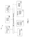
- Fig. 1 is a block diagram of an example electronic system 100.
- Electronic system 100 may be, for example, a computer, a server, a network switch or a router for a communication network.
- Electronic system 100 includes communication channels 102, system control logic 104, system memory 106, input/output (I/O) interfaces 108, mass storage 110, switch element 112, endpoints 114, and capacity manager 116, each coupled as depicted.
- I/O input/output
- system control logic 104 controls the overall operation of electronic system 100 and is intended to represent any of a wide variety of logic device(s) and/or executable content to control the operation of electronic system 100.
- System control logic 104 may include a microprocessor, network processor, microcontroller, field programmable gate array (FPGA), application specific integrated chip (ASIC), executable content to implement such control features and/or any combination thereof.
- FPGA field programmable gate array
- ASIC application specific integrated chip
- System memory 106 stores information such as temporary variables or intermediate information. This information may be stored during execution of instructions by system control logic 104. System memory 106 may also temporarily store data selected for forwarding by electronic system 100 to either elements within electronic system 100 (e.g., switch element 112 and/or endpoints 114) via communication channels 102 or elements remote to electronic system 100 via system I/O interfaces 108. The data may either originate from electronic system 100 (e.g., system control logic 102 or system applications 116) or may be received by electronic system 100 via system I/O interfaces 108.
- elements within electronic system 100 e.g., switch element 112 and/or endpoints 11
- the data may either originate from electronic system 100 (e.g., system control logic 102 or system applications 116) or may be received by electronic system 100 via system I/O interfaces 108.
- System applications 116 may provide internal instructions to system control logic 104, for example, to assist in the forwarding of data within/outside of electronic system 100.
- Endpoints 114 are elements within electronic system 100 that may serve as I/O endpoints to process the data to be transmitted/received on a communication link.
- the communication link may be located within electronic system 100 (e.g., included within communication channels 102).
- the communication link may also be located externally to electronic system 100.
- endpoints 114 may act as the I/O endpoint for electronic system 100 which is linked to another I/O processing endpoint in another electronic system through system I/O interfaces 108 via direct and/or remote communication links.
- Direct communication links may be via links utilizing communication standards such as Ethernet, SONET, asynchronous transfer mode (ATM) or the like.
- Remote communication links may be via wireless links utilizing such wireless communication standards as IEEE 802.11 and/or IEEE 802.16 or the like.
- data may be forwarded through one or more communication links within electronic system 100. These communication links may be included within communication channels 102 and may consist of one or more point-to-point communication links. The data may be forwarded from one endpoint 114 to another endpoint 114 through one or more of these point-to-point communication links. In one implementation, the data is also forwarded within electronic system 100 on a point-to-point communication link with an intermediary such as switch element 112. The data may then be forwarded from the intermediary to another endpoint 114 on another point-to-point communication link.
- intermediary such as switch element 112.
- VC queues are utilized to facilitate the efficient forwarding of the data on a point-to-point communication link.
- these VC queues may provide a means of supporting multiple independent logical communication channels on the point-to-point communication link.
- endpoint 114 and switch element 112 may be "link partners" on a point-to-point communication link.
- link partners data forwarded from endpoint 114 to switch element 112 may be logically channeled by multiplexing streams of the data onto one or more VCs queues responsive to and/or resident within switch element 112.
- VC queue capacity or space is needed by switch element 112.
- FC flow control
- DLLPs data link layer packets
- capacity manager 116 may monitor available space in a device's (e.g., switch element 112 or endpoints 114) VC queue for a point-to-point communication link with a link partner device.
- FIG. 2 is an example architectural diagram of capacity manager 116.
- capacity manager 116 includes a monitor engine 210, control logic 220, memory 230, I/O interfaces 240, and optionally one or more application(s) 250, each coupled as depicted.
- monitor engine 210 includes a credit feature 212, comparison feature 214 and communication feature 216. These features monitor available space in a VC queue for a communication link, compare the available space in the VC queue to available space in one or more other VC queues for the communication link and communicate the determined available space to an arbiter. The arbiter may then modify one or more parameters for an arbitration scheme to change the utilization rate of the VC queue relative to the one or more other VC queues based on the comparison.
- Control logic 220 may control the overall operation of capacity manager 116 and is intended to represent any of a wide variety of logic device(s) and/or executable content to implement the control of capacity manager 116.
- control logic 220 may include of a microprocessor, network processor, microcontroller, FPGA, ASIC, or executable content to implement such control features, and/or any combination thereof.
- the features and functionality of control logic 220 may be implemented within monitor engine 210.
- memory 230 is used by monitor engine 210 to temporarily store information related to the monitoring of and the comparison of available space in a VC queue.
- Memory 230 may also store executable content. The executable content may be used by control logic 220 to implement an instance of monitor engine 210.
- I/O interfaces 240 may provide a communications interface between capacity manager 116 and an electronic system (e.g., electronic system 100).
- capacity manager 116 is implemented as an element of a computer system.
- I/O interfaces 240 may provide a communications interface between capacity manager 116 and the computer system via a communication channel.
- control logic 220 can receive a series of instructions from application software external to capacity manager 116 via I/O interfaces 240. The series of instructions may invoke control logic 220 to implement one or more features of monitor engine 210.
- capacity manager 116 includes one or more application(s) 250 to provide internal instructions to control logic 220.
- application(s) 250 may be invoked to generate a user interface, e.g., a graphical user interface (GUI), to enable administrative features, and the like.
- GUI graphical user interface
- one or more features of monitor engine 210 may be implemented as an application(s) 250, selectively invoked by control logic 220 to invoke such features.
- monitor engine 210 may invoke an instance of credit feature 212 to monitor the available space of a VC queue in switch element 112.
- the VC queue may be a VC receive and/or transmit queue for a point-to-point communication link to a link partner (e.g., coupled to endpoints 114).
- Credit feature 212 may temporarily store the available space information in a memory (e.g., memory 230).
- Monitor engine 210 may also invoke an instance of comparison feature 214. Comparison feature 214 may access the available space information and then compare the available space in the VC queue relative to one or more other VC queues in switch element 112 for the point-to-point communication link. Monitor engine 210 may then invoke communication feature 216 to communicate the comparison to an arbiter.
- the arbiter for example, may modify one or more parameters for an arbitration scheme to change the utilization rate of the VC queue relative to the other VC queues.
- capacity manager 116 may be located outside of switch element 112 to monitor available space in a VC queue resident within and/or responsive to switch element 112 and communicate any comparisons of available space to an arbiter within and/or outside of switch element 112.
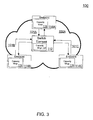
- Fig. 3 is an example graphical illustration of elements of electronic system 100 coupled by an Advanced Switching (AS) fabric 102A.
- communication channels 102 may include communication links (e.g., fabric) that may operate in compliance with the AS standard (e.g., AS fabric 102A).
- AS standard e.g., AS fabric 102A
- elements of electronic system 100 e.g., switch element 112, endpoints 114) may forward data on AS 102A. These elements may also operate in compliance with the AS standard and may route the data via point-to-point communication links 101A-C.
- the data may be encapsulated by the inclusion of one or more headers containing route and handling information. As described in more detail below, these headers may utilize one or more communication protocols described in the AS standard.
- switch element 112 and endpoints 114A-C are coupled to AS fabric 102A. Additionally, switch element 112 is coupled to endpoints 114A-C through point-to-point communication links 101A-C.
- AS fabric 102A may be included within communication channels 102 in electronic system 100.
- endpoints 114A-C and switch element 112 may communicate through other point-to-point communication links in addition to those depicted in Fig. 3 .
- endpoint 114A may have a point-to-point communication link with endpoint 114B and/or 114C.
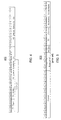
- Fig. 4 is a graphical illustration of an example VC FC DLLP 400.
- DLLP 400 depicts a packet format that contains 32-bits of data with a 16-bit cyclic redundancy check.
- DLLP 400 includes fields to indicate flow control type, VC identification (ID) and queue credits for one or more VC queues associated with the VC ID.
- ID VC identification
- the FC type field in bits 28-31 indicates the type of VC FC credit.
- the type of VC FC credit may be an initialization VC FC credit or may be an update/refresh VC FC credit, although types of VC FC credits are not limited to only these types of VC FC credits.
- an initialization VC FC credit is exchanged between link partners when a point-to-point communication link is initiated between devices (e.g., endpoint 1114A and switch element 112).
- an update VC FC credit is exchanged between link partners after initialization.
- Update VC FC DLLPs in the format of DLLP 400 may continue to be exchanged at a given interval.
- the interval is not limited to only a particular given/fixed interval. The interval, for example, may vary based on such factors as link congestion, caused by, for example, VC queues lacking enough available space to forward data.
- the VC index field in bits 24-27 indicates what given VC ID(s) is associated with the VC FC DLLP being exchanged between the link partners.
- the VC index field is associated with the AS standard's assignment of one or more VC identification numbers (IDs) to a given VC index.
- the assignments may be based on the type of VC queue being either a "bypass capable" or "ordered only.”
- a bypass capable VC has both a bypass queue and an ordered queue.
- only one VC ID is associated with a given VC index number for a bypass capable VC.
- An ordered only VC contains just an ordered queue.
- two VC IDs are associated with a given VC index number for an ordered only VC.
- the VC queue credits (B) field in bits 12-23 will indicate the amount of queue credits (e.g., space available in bits, bytes or d-words) in the bypass queue and the VC queue credits (A) field in bits 0-11 will indicate the amount of credits in the ordered queue. If the VC FC DLLP is associated with an ordered only VC, then the VC queue credits (B) field will indicate the amount of queue credits for one VC ID and the VC queue credits (A) will indicate the amount of queue credits for another VC ID.
- the AS and PCI-Express standards describe a number of congestion management techniques, one of which is a credit-based flow control technique that ensures that data is not lost due to congestion.
- congestion management techniques one of which is a credit-based flow control technique that ensures that data is not lost due to congestion.
- communication link partners in a communication network e.g., switch element 112 and endpoints 114A-C
- exchange flow control credit information to guarantee that the receiving end of a communication link has the available space or capacity in a VC queue to accept data.
- Flow control credits are computed on a VC-basis by the receiving end of the communication link and communicated to the transmitting end of the communication link.
- data is transmitted only when there are enough credits available for a particular VC queue to receive the data.
- the transmitting end of the communication link debits its available credit account by an amount of flow control credits that reflects a size of the data.
- the receiving end of the communication link processes the received data (e.g., performs handling and/or routing functions), space is made available on the corresponding VC queue.
- an update VC FC DLLP in the format of DLLP 400 is returned to the transmission end of the communication link. After receiving the update VC FC DLLP, the transmission end of the communication link may then update its available credit account to match the available credits indicated in the update VC FC DLLP.
- Fig. 5 is a graphical illustration of a portion of an example AS route header 500.
- AS route header 500 depicts a typical AS route header format containing 32-bits of data.
- the AS standard describes the 32-bits of data as including fields to indicate credits required, VC type specific (TS), ordered only (OO) traffic class (TC) and protocol interface (PI).
- TS VC type specific
- OO ordered only
- TC traffic class
- PI protocol interface
- the credits required field in bits 14-18 indicates the amount of credits that are needed to forward data through a VC queue for a communication link.
- the data including a packet header in the format of AS route header 500
- bits 14-18 are selectively asserted to indicate that credits amounting to 128 bytes are required to forward the data.
- the TS field in bit 13 indicates whether bypass or ordered VC queue credits are to be consumed as the data is routed through a VC queue. For example, if bit 13 is asserted, the data consumes bypass credit and is bypass-able. If bit 13 is not asserted, the data consumes ordered credit and is not bypassable.
- the OO field in bit 12 indicates what type of VC queue the data is routed through. For example, if bit 12 is asserted, the data is routed through an ordered-only VC queue. If bit 12 is not asserted, the data can be routed through either the bypassable or ordered queue of a bypass capable VC queue.
- the traffic class (TC) field in bits 9-11 indicate the traffic class associated with the data.
- the AS standard describes several TCs that, for example, enable class of service differentiation for different types of data to be forwarded on an AS fabric.
- one or more TCs may be mapped to a given VC queue ("TC-to-VC mapping").
- the TC field may indicate the given VC queue data is routed through based on the TC-to-VC mapping.
- the PI field in bits 0-6 identifies the type of data being routed through a VC queue the type of data may indicate specific AS fabric transport services performed on the data as it is forwarded through elements on an AS fabric. For example, transportation services such as congestion management, multicast, and segmentation and reassembly, although AS fabric transport services are not limited to these examples.
- the AS standard assigns these transportation services to a particular PI. For example, segmentation and reassembly transportation services are assigned to a particular PI called "PI-2.”
- bits 0-6 in AS route header 500 may be selectively asserted to indicate PI-2 if the data is associated with segmentation and reassembly transportation services.
- switch element 112 and/or endpoints 114 may have resources (e.g., an ASIC, FPGA, special function controller or embedded processor, other hardware device and firmware or software) to perform transportation services assigned to a given PI. These resources may be referred to as "PI processing elements" and may reside within and/or are responsive to switch element 112 and/or endpoints 114. In an example implementation, data to be forwarded through a VC queue may be routed to these PI processing elements based on the PI indicated in PI field of an AS route header in the format of AS route header 500.
- resources e.g., an ASIC, FPGA, special function controller or embedded processor, other hardware device and firmware or software
- Bits 19-31 and 8-9 are reserved for other types of AS route information. This information may further facilitate the forwarding of the data through an AS fabric.
- Fig. 6 is an example block diagram of a capacity manager 116 monitoring VC queues in switch element 112.
- Switch element 112 is shown in Fig. 6 as including an AS transaction layer 600 having a four VC receive and transmit path, although the disclosure is not limited to a four VC receive and transmit path.
- data is received by switch element 112 from AS fabric 102A over a point-to-point communication link (e.g., point-to-point communication link 101A-C).
- the data is passed from the physical link layer to the AS data/link layer.
- acknowledgement data may be generated and transmitted to the transmitting device (e.g. endpoints 114A-C), and one or more transaction layer packets are generated from the data and are passed to the inbound packet director 605.
- the transaction layer packet passed to inbound packet director 605 includes an AS route header in the format of AS route header 500.
- Inbound packet director 605 reads the TC field in the AS route header and writes the transaction layer packet to a VC receive queue 610A-D based at least in part on the TC-to-VC mapping that is stored at (or is otherwise accessible by) the inbound packet director 605.
- the transaction layer packet may be routed to one of the four VC receive queues 610A-D.
- At lease one VC receive queue 610A-D may be implemented as a first-in-first-out (FIFO) queue that passes transaction layer packets to its corresponding VC packet dispatch unit 615A-D in the order received. For example, packets on VC receive queue 610C are passed to its corresponding VC packet dispatch unit 615C.
- FIFO first-in-first-out
- the packet dispatch reads the protocol interface field in the AS route header and based on the PI indicated, notifies an arbiter 622 for a PI processing element(s) 620.
- the notification may be that a transaction layer packet awaits forwarding.
- arbiter 622 arbitrates between multiple notifications sent by VC packet dispatch units 615A-D and selects a VC queue using an arbitration scheme.
- An arbitration scheme may include, but is not limited to, round-robin, weighted round-robin, or round robin including a fairness protocol.
- PI processing element(s) 620 once PI processing element(s) 620 completes its handling/processing of the transaction layer packet, it notifies one of the four VC arbiters 620A-D.
- the particular VC arbiter notified for example, is based on the TC field in the AS route header and the corresponding TC-to-VC mapping for the transmit queues. This TC-to-VC mapping is stored at (or is otherwise accessible by) the processing element(s) 620.
- multiple PI processing element(s) 620 may be notifying a given VC arbiter 620A-D that data is ready to be forwarded.
- Arbiter 620A-D may arbitrate between the multiple notifications and may select which PI processing element(s) 620 to allow to forward the data to its corresponding VC transmit queue 625A-D. The selection may be made utilizing an arbitration scheme that may include but is not limited to those arbitration schemes mentioned above.
- At least one VC transmit queue 625A-D may be implemented as a FIFO queue.
- the VC transmit queue notifies outbound packet arbiter 630 that a transaction layer packet is ready for transmission.
- outbound packet arbiter 630 may read the credits required field in the AS route header.
- Outbound packet arbiter 630 may then determine if switch element 112's link partner (e.g., endpoints 114A-C) has sufficient VC receive queue credits to receive the data associated with the transaction layer packet over that VC. If the link partner has adequate credits, outbound packet arbiter 630 passes down the data in the transaction layer packet to the AS data/link layer where the data is further passed down to the physical link layer and transmitted on a point-to-point communication link in AS fabric 102A.
- switch element 112's link partner e.g., endpoints 114A-C
- capacity manager 116 monitors VC queue capacities in VC receive queues 610A-D by reading the update VC FC DLLPs transmitted by inbound packet director 605 Capacity manager 116 may then compare the available space in a given VC receive queue to one or more other VC receive queues. Capacity manager 116 may then communicate that comparison to, for example, arbiter 622. Arbiter 622 may then modify one or more parameters for an arbitration scheme that may change the utilization rate of the given VC receive queue relative to the one or more other VC receive queues.
- arbiter 622 may use a weighted round robin (WWR) arbitration scheme. If the comparison shows an imbalance (e.g., greater than a 10% difference) in the available space of one VC receive queue compared to other VC receive queues, one or more parameters (e.g., algorithm coefficients) to the WWR arbitration scheme may be modified. The modification may change the utilization rate of that VC queue by the arbiter to equalize that VC receive queue's available space as compared to the other VC receive queues.
- WWR weighted round robin
- capacity manager 116 monitors available space in VC transmit queues 625A-D by starting from a given credit capacity for a given VC transmit queue. Capacity manager 116 may then read the credits required field of the AS route header for a transaction layer packet written into a given VC transmit queue (e.g., by PI processing element(s) 620). Capacity manager 116 may then subtract from the given credit capacity the credits indicated in the AS route header. Then when the transaction layer packet is transmitted from a given transmit VC queue, the capacity manager 116 adds back the credits indicated in the AS route header. Capacity manager 116 may maintain an available space table reflecting this credit capacity accounting in a memory (e.g., memory 230).
- a memory e.g., memory 230
- Fig. 7 is a flow chart of an example method to monitor available space in a VC queue for a communication link.
- the method for example may be for AS transaction layer 600's four VC receive and transmit path depicted in Fig. 6 .
- monitor engine 210 invokes an instance of credit feature 212.
- credit feature 212 reads the VC queue credit fields of an update VC FC DLLP transmitted by inbound packet director 605.
- the update VC FC DLLP may be in the format of DLLP 400 and may be associated with a given VC receive queue.
- Credit feature 212 may then temporarily store (e.g., in memory 230) the indicated available space in an available space table for the given VC receive queue.
- credit feature 212 reads the credits required field of a AS route header.
- the AS route header may be for a transaction layer packet written into a VC transmit queue (e.g., VC transmit queue 625A-D) by PI processing element(s) 620.
- Credit feature 212 may access an available space table for the VC transmit queue from a memory (e.g., memory 230). Credit feature 212 may then subtract the indicated credits from the available space table to update that table. Then when the transaction layer packet is transmitted from the VC transmit queue, credit feature 212 accesses the table and adds back the credits indicated in the AS route header to update the table again.
- monitor engine 210 invokes an instance of comparison feature 214 to compare the available space in a VC queue compared to one or more other VC queues.
- comparison feature 214 may compare the available space in VC receive queue 610A relative to VC receive queues 610B-C.
- Comparison feature 214 may access the available space tables for VC receive queues 610A-D.
- Comparison feature 214 may then compare the available space in VC receive queue 610A to the available space in VC receive queues 610B-D.
- comparison feature 214 determines if the comparison of the available space in a VC queue shows an imbalance. For example, comparison feature 214's comparison may show that VC receive queue 610A has available space of less than 10% and VC receive queues 610B-D have an average available space that is higher than 10% (e.g., 15% or 20%). In one implementation, comparison feature 214 may determine that this difference in available space equates to an imbalance. If comparison feature 214 determines an imbalance exists, the process moves to block 740. If comparison feature 214 determines that no imbalance exists, the process moves to block 750.
- monitor engine 210 invokes an instance of communication feature 216 to communicate the results of the comparison by comparison feature 214 to an arbiter.
- communication feature 216 may communicate the comparison information (e.g., the level of the imbalance) to arbiter 622.
- Arbiter 622 based on the comparison may modify one or more parameters of an arbitration scheme used to decide which transaction layer packet to process from a given VC receive queue. This parameter modification may change the utilization rate of VC receive queue 610A relative to VC receive queues 610B-D and thus reduce the imbalance.
- the process may then start over to monitor any of the VC receive queues in the four VC receive and transmit path depicted in Fig. 6 .
- the monitoring and resulting comparison(s) may occur, for example, on a periodic or a continual basis.
- Switch element 114 may represent an element of electronic system 100 that may act as an intermediary to forward or process data transmitted within electronic system 100 (e.g., on AS fabric 102A).
- switch element 112 may include one or more of a switch blade or a router for electronic system 100.
- Endpoints 114 may represent elements of electronic system 100 which act as either an input (ingress) or output (egress) node situated on communication channels 102. Endpoints 114 may represent any of a number of hardware and/or software element(s) to receive and transmit data. In this regard, according to one example, endpoints 114 may include one or more of a bridge, a microprocessor, network processor, software application, embedded logic, or the like.
- capacity manager 116 may be encompassed within switch element 112 or endpoints 114. Alternatively, capacity manager 116 may be responsive to or communicatively coupled to switch element 112 and endpoints 114 through communication channels 102.
- capacity manager 116 may be implemented in hardware, software, firmware, or any combination thereof.
- capacity manager 116 may be implemented as one or more of an ASIC, special function controller or processor, FPGA, other hardware device and firmware or software to perform at least the functions described in this disclosure.
- System memory 106 and/or memory 230 may include a wide variety of memory media including but not limited to volatile memory, non-volatile memory, flash, programmable variables or states, random access memory (RAM), read-only memory (ROM), flash, or other static or dynamic storage media.
- volatile memory non-volatile memory
- flash programmable variables or states
- RAM random access memory
- ROM read-only memory
- flash or other static or dynamic storage media.
- memory responsive to a device may include one or more VC queues for a communication link.
- This memory may include RAM.
- RAM may include, but is not limited to, ferroelectric RAM (FRAM), dynamic RAM (DRAM), static RAM (SRAM), extended data output RAM (EDO RAM), synchronous DRAM (SDRAM).
- machine-readable instructions can be provided to system memory 106 and/or memory 230 from a form of machine-accessible medium.
- a machine-accessible medium may represent any mechanism that provides (i.e., stores and/or transmits) information in a form readable by a machine (e.g., switch element 112 or endpoints 114).
- a machine-accessible medium may include: ROM; RAM; magnetic disk storage media; optical storage media; flash memory devices; electrical, optical, acoustical or other form of propagated signals (e.g., carrier waves, infrared signals, digital signals); and the like.
- references made in the specification to the term “responsive to” are not limited to responsiveness to only a particular feature and/or structure.
- a feature may also be “responsive to” another feature and/or structure and also be located within that feature and/or structure.
- responsive to may also be synonymous with other terms such as “communicatively coupled to” or “operatively coupled to,” although the term is not limited in his regard.
Landscapes
- Engineering & Computer Science (AREA)
- Computer Networks & Wireless Communication (AREA)
- Signal Processing (AREA)
- Data Exchanges In Wide-Area Networks (AREA)
- Small-Scale Networks (AREA)
Description
- Communication networks typically use high speed serial interconnects to route data and/or instructions (hereinafter referred to as "data") between devices in a communication network. Various industry standards and/or proprietary communication protocols are used to facilitate the forwarding of data from one or more source devices to one or more destination devices in the communication network. Some examples of industry standards are the PCI-Express Base Specification, Rev. 1.1, published March 28, 2005, ("the PCI-Express standard") and the Advanced Switching Core Architecture Specification, Rev. 1.0, published December 2003, ("the AS standard").
- Devices compliant with the PCI-Express and/or AS standards communicate with each other and forward data between the devices on point-to-point communication links using a three layer communication protocol. This three layer communication protocol may result in the data passing through a physical layer, a data link layer and a transaction layer. At the physical layer, electronic pulses are converted to byte oriented packets and passed to the data link layer. At the data link layer, the packets are validated, acknowledgement packets are generated to the transmitting device and transaction layer packets are passed up to the device. At the transaction layer, the transaction layer packets may indicate to the device to perform an action. This action may include, but is not limited to, forwarding the data onto one or more other devices in the communication network.
- Devices compliant with the PCI-Express and/or AS standards each contain a plurality of queues described in these standards as "Virtual Channels," or "VC queues." These VC queues provide a means of supporting multiple independent "logical data flows" over a communication link. This may involve the multiplexing of different data flows on a single communication link between devices. Each device manages VC queue usage with its communication link partner through the use of in-band flow control packets called VC flow control data link layer packets or "VC TC DLLPs." A VC FC DLLP will indicate to the other communication link partner the available space (flow control credits) of a given VC queue. If the flow control credits are exhausted, the communication link partner cannot transmit data on that VC queue until the receiving partner makes space available and sends another VC FC DLLP to indicate space is available.
- When a link partner is a switching device with multiple switch ports to one or more other devices, multiple switch ports may utilize the same given VC queue to forward data. If the flow control credits are exhausted for the given VC queue, a ripple effect may result. This ripple effect may lead to congestion as multiple link partners must wait for the exhausted VC queue to replenish its flow control credits before transmitting data to the switching device. This is problematic in situations where an over-utilized VC queue may result in congestion that negatively impacts increasing portions of a communication network.
US-B1-6 834 053 discloses a distributed traffic scheduler comprising monitoring mechanisms which monitor the sum of various classes of queue traffic stored at a given within the class scheduler queues. A number of alarms are raised when respective thresholds, set by a user, for each queue, are exceeded.
US-A-5 914 936 discloses an ATM exchange performing traffic flow control comprising comparison of a single queue length to two threshold levels.
US-B1-6 762 994 discloses a high speed traffic management control using lookup tables to compare statistical information of respective queues each to threshold level information. -
-
Fig. 1 is a block diagram of an example electronic system; -
Fig. 2 is an example architectural diagram of a capacity manager; -
Fig. 3 is an example graphical illustration of elements of the electronic system coupled by an Advanced Switching (AS) fabric; -
Fig. 4 is a graphical illustration of an example virtual channel (VC) flow control (FC) data link layer packet (DLLP); -
Fig. 5 is a graphical illustration of a portion of an example AS route header; -
Fig. 6 is an example block diagram of a capacity manager monitoring VC queues in a switch element; and -
Fig. 7 is a flow chart of an example method to monitor available space in a VC queue for a communication link. - Examples in this disclosure are generally directed to monitoring a queue for a communication link. A capacity manager is described that monitors available space in a VC queue for a communication link. The capacity manager may compare the available space to available space in another VC queue for the communication link. The capacity manager may then communicate the comparison to an arbiter. The arbiter may modify a parameter for an arbitration scheme to change a utilization rate of the VC queue relative to the other VC queue based on the comparison.
-
Fig. 1 is a block diagram of an exampleelectronic system 100.Electronic system 100 may be, for example, a computer, a server, a network switch or a router for a communication network.Electronic system 100 includescommunication channels 102,system control logic 104,system memory 106, input/output (I/O)interfaces 108,mass storage 110,switch element 112,endpoints 114, andcapacity manager 116, each coupled as depicted. - In one example,
system control logic 104 controls the overall operation ofelectronic system 100 and is intended to represent any of a wide variety of logic device(s) and/or executable content to control the operation ofelectronic system 100.System control logic 104 may include a microprocessor, network processor, microcontroller, field programmable gate array (FPGA), application specific integrated chip (ASIC), executable content to implement such control features and/or any combination thereof. -
System memory 106 stores information such as temporary variables or intermediate information. This information may be stored during execution of instructions bysystem control logic 104.System memory 106 may also temporarily store data selected for forwarding byelectronic system 100 to either elements within electronic system 100 (e.g.,switch element 112 and/or endpoints 114) viacommunication channels 102 or elements remote toelectronic system 100 via system I/O interfaces 108. The data may either originate from electronic system 100 (e.g.,system control logic 102 or system applications 116) or may be received byelectronic system 100 via system I/O interfaces 108. -
System applications 116 may provide internal instructions tosystem control logic 104, for example, to assist in the forwarding of data within/outside ofelectronic system 100. -
Endpoints 114 are elements withinelectronic system 100 that may serve as I/O endpoints to process the data to be transmitted/received on a communication link. The communication link may be located within electronic system 100 (e.g., included within communication channels 102). The communication link may also be located externally toelectronic system 100. For example,endpoints 114 may act as the I/O endpoint forelectronic system 100 which is linked to another I/O processing endpoint in another electronic system through system I/O interfaces 108 via direct and/or remote communication links. Direct communication links may be via links utilizing communication standards such as Ethernet, SONET, asynchronous transfer mode (ATM) or the like. Remote communication links may be via wireless links utilizing such wireless communication standards as IEEE 802.11 and/or IEEE 802.16 or the like. - In one example, data may be forwarded through one or more communication links within
electronic system 100. These communication links may be included withincommunication channels 102 and may consist of one or more point-to-point communication links. The data may be forwarded from oneendpoint 114 to anotherendpoint 114 through one or more of these point-to-point communication links. In one implementation, the data is also forwarded withinelectronic system 100 on a point-to-point communication link with an intermediary such asswitch element 112. The data may then be forwarded from the intermediary to anotherendpoint 114 on another point-to-point communication link. - In one implementation, VC queues are utilized to facilitate the efficient forwarding of the data on a point-to-point communication link. As introduced above, these VC queues may provide a means of supporting multiple independent logical communication channels on the point-to-point communication link. For example,
endpoint 114 andswitch element 112 may be "link partners" on a point-to-point communication link. As link partners, data forwarded fromendpoint 114 to switchelement 112 may be logically channeled by multiplexing streams of the data onto one or more VCs queues responsive to and/or resident withinswitch element 112. - Before the data can be forwarded through the point-to-point communication link, adequate VC queue capacity or space is needed by switch
element 112. As will be explained in more detail below, one indication of adequate VC queue capacity or space may be communicated to a link partner by exchanging VC flow control (FC) data link layer packets (DLLPs) with the link partner. VC FC DLLPs may indicate available VC queue space, for example, measured in bits, bytes, d-words (4-bytes), and the like. - In one example,
capacity manager 116 may monitor available space in a device's (e.g.,switch element 112 or endpoints 114) VC queue for a point-to-point communication link with a link partner device. -
Fig. 2 is an example architectural diagram ofcapacity manager 116. InFig. 2 ,capacity manager 116 includes amonitor engine 210,control logic 220,memory 230, I/O interfaces 240, and optionally one or more application(s) 250, each coupled as depicted. - In
Fig. 2 , monitorengine 210 includes acredit feature 212,comparison feature 214 andcommunication feature 216. These features monitor available space in a VC queue for a communication link, compare the available space in the VC queue to available space in one or more other VC queues for the communication link and communicate the determined available space to an arbiter. The arbiter may then modify one or more parameters for an arbitration scheme to change the utilization rate of the VC queue relative to the one or more other VC queues based on the comparison. -
Control logic 220 may control the overall operation ofcapacity manager 116 and is intended to represent any of a wide variety of logic device(s) and/or executable content to implement the control ofcapacity manager 116. In this regard,control logic 220 may include of a microprocessor, network processor, microcontroller, FPGA, ASIC, or executable content to implement such control features, and/or any combination thereof. In alternate examples, the features and functionality ofcontrol logic 220 may be implemented withinmonitor engine 210. - According to one example,
memory 230 is used bymonitor engine 210 to temporarily store information related to the monitoring of and the comparison of available space in a VC queue.Memory 230 may also store executable content. The executable content may be used bycontrol logic 220 to implement an instance ofmonitor engine 210. - I/O interfaces 240 may provide a communications interface between
capacity manager 116 and an electronic system (e.g., electronic system 100). For example,capacity manager 116 is implemented as an element of a computer system. I/O interfaces 240 may provide a communications interface betweencapacity manager 116 and the computer system via a communication channel. As a result,control logic 220 can receive a series of instructions from application software external tocapacity manager 116 via I/O interfaces 240. The series of instructions may invokecontrol logic 220 to implement one or more features ofmonitor engine 210. - In one example,
capacity manager 116 includes one or more application(s) 250 to provide internal instructions to controllogic 220. Such application(s) 250 may be invoked to generate a user interface, e.g., a graphical user interface (GUI), to enable administrative features, and the like. In alternate examples, one or more features ofmonitor engine 210 may be implemented as an application(s) 250, selectively invoked bycontrol logic 220 to invoke such features. - In one implementation,
monitor engine 210 may invoke an instance ofcredit feature 212 to monitor the available space of a VC queue inswitch element 112. The VC queue, for example, may be a VC receive and/or transmit queue for a point-to-point communication link to a link partner (e.g., coupled to endpoints 114).Credit feature 212 may temporarily store the available space information in a memory (e.g., memory 230). -
Monitor engine 210 may also invoke an instance ofcomparison feature 214.Comparison feature 214 may access the available space information and then compare the available space in the VC queue relative to one or more other VC queues inswitch element 112 for the point-to-point communication link.Monitor engine 210 may then invokecommunication feature 216 to communicate the comparison to an arbiter. The arbiter, for example, may modify one or more parameters for an arbitration scheme to change the utilization rate of the VC queue relative to the other VC queues. - In one implementation,
capacity manager 116 may be located outside ofswitch element 112 to monitor available space in a VC queue resident within and/or responsive to switchelement 112 and communicate any comparisons of available space to an arbiter within and/or outside ofswitch element 112. -
Fig. 3 is an example graphical illustration of elements ofelectronic system 100 coupled by an Advanced Switching (AS)fabric 102A. In one example,communication channels 102 may include communication links (e.g., fabric) that may operate in compliance with the AS standard (e.g., ASfabric 102A). Additionally, elements of electronic system 100 (e.g.,switch element 112, endpoints 114) may forward data onAS 102A. These elements may also operate in compliance with the AS standard and may route the data via point-to-point communication links 101A-C. In one implementation, the data may be encapsulated by the inclusion of one or more headers containing route and handling information. As described in more detail below, these headers may utilize one or more communication protocols described in the AS standard. - As depicted in
Fig. 3 ,switch element 112 andendpoints 114A-C are coupled to ASfabric 102A. Additionally,switch element 112 is coupled toendpoints 114A-C through point-to-point communication links 101A-C. As mentioned above, ASfabric 102A may be included withincommunication channels 102 inelectronic system 100. As a result,endpoints 114A-C andswitch element 112 may communicate through other point-to-point communication links in addition to those depicted inFig. 3 . For example,endpoint 114A may have a point-to-point communication link withendpoint 114B and/or 114C. -
Fig. 4 is a graphical illustration of an exampleVC FC DLLP 400.DLLP 400 depicts a packet format that contains 32-bits of data with a 16-bit cyclic redundancy check.DLLP 400 includes fields to indicate flow control type, VC identification (ID) and queue credits for one or more VC queues associated with the VC ID. - In one example, the FC type field in bits 28-31 indicates the type of VC FC credit. The type of VC FC credit may be an initialization VC FC credit or may be an update/refresh VC FC credit, although types of VC FC credits are not limited to only these types of VC FC credits. In one implementation, an initialization VC FC credit is exchanged between link partners when a point-to-point communication link is initiated between devices (e.g., endpoint 1114A and switch element 112). In another implementation, an update VC FC credit is exchanged between link partners after initialization. Update VC FC DLLPs in the format of
DLLP 400 may continue to be exchanged at a given interval. The interval is not limited to only a particular given/fixed interval. The interval, for example, may vary based on such factors as link congestion, caused by, for example, VC queues lacking enough available space to forward data. - The VC index field in bits 24-27 indicates what given VC ID(s) is associated with the VC FC DLLP being exchanged between the link partners. In one implementation, the VC index field is associated with the AS standard's assignment of one or more VC identification numbers (IDs) to a given VC index. The assignments may be based on the type of VC queue being either a "bypass capable" or "ordered only." A bypass capable VC has both a bypass queue and an ordered queue. As a result, only one VC ID is associated with a given VC index number for a bypass capable VC. An ordered only VC contains just an ordered queue. As a result, two VC IDs are associated with a given VC index number for an ordered only VC.
- In one example, if a VC FC DLLP is associated with a bypass capable VC, the VC queue credits (B) field in bits 12-23 will indicate the amount of queue credits (e.g., space available in bits, bytes or d-words) in the bypass queue and the VC queue credits (A) field in bits 0-11 will indicate the amount of credits in the ordered queue. If the VC FC DLLP is associated with an ordered only VC, then the VC queue credits (B) field will indicate the amount of queue credits for one VC ID and the VC queue credits (A) will indicate the amount of queue credits for another VC ID.
- The AS and PCI-Express standards describe a number of congestion management techniques, one of which is a credit-based flow control technique that ensures that data is not lost due to congestion. For example, communication link partners in a communication network (e.g.,
switch element 112 andendpoints 114A-C) exchange flow control credit information to guarantee that the receiving end of a communication link has the available space or capacity in a VC queue to accept data. - Flow control credits are computed on a VC-basis by the receiving end of the communication link and communicated to the transmitting end of the communication link. Typically, data is transmitted only when there are enough credits available for a particular VC queue to receive the data. Upon sending data, the transmitting end of the communication link debits its available credit account by an amount of flow control credits that reflects a size of the data. As the receiving end of the communication link processes the received data (e.g., performs handling and/or routing functions), space is made available on the corresponding VC queue. In one implementation, an update VC FC DLLP in the format of
DLLP 400 is returned to the transmission end of the communication link. After receiving the update VC FC DLLP, the transmission end of the communication link may then update its available credit account to match the available credits indicated in the update VC FC DLLP. -
Fig. 5 is a graphical illustration of a portion of an example ASroute header 500. ASroute header 500 depicts a typical AS route header format containing 32-bits of data. The AS standard describes the 32-bits of data as including fields to indicate credits required, VC type specific (TS), ordered only (OO) traffic class (TC) and protocol interface (PI). - In one implementation, the credits required field in bits 14-18 indicates the amount of credits that are needed to forward data through a VC queue for a communication link. For example, the data (including a packet header in the format of AS route header 500) may require 128 bytes (16 d-words) of VC queue space to be forwarded through the VC queue. As a result, bits 14-18 are selectively asserted to indicate that credits amounting to 128 bytes are required to forward the data.
- In one implementation, the TS field in
bit 13 indicates whether bypass or ordered VC queue credits are to be consumed as the data is routed through a VC queue. For example, ifbit 13 is asserted, the data consumes bypass credit and is bypass-able. Ifbit 13 is not asserted, the data consumes ordered credit and is not bypassable. - In one implementation, the OO field in
bit 12 indicates what type of VC queue the data is routed through. For example, ifbit 12 is asserted, the data is routed through an ordered-only VC queue. Ifbit 12 is not asserted, the data can be routed through either the bypassable or ordered queue of a bypass capable VC queue. - In one implementation, the traffic class (TC) field in bits 9-11 indicate the traffic class associated with the data. The AS standard describes several TCs that, for example, enable class of service differentiation for different types of data to be forwarded on an AS fabric. To facilitate the- efficient transmission of the data, one or more TCs may be mapped to a given VC queue ("TC-to-VC mapping"). Thus, the TC field may indicate the given VC queue data is routed through based on the TC-to-VC mapping.
- In one implementation, the PI field in bits 0-6 identifies the type of data being routed through a VC queue the type of data may indicate specific AS fabric transport services performed on the data as it is forwarded through elements on an AS fabric. For example, transportation services such as congestion management, multicast, and segmentation and reassembly, although AS fabric transport services are not limited to these examples. The AS standard assigns these transportation services to a particular PI. For example, segmentation and reassembly transportation services are assigned to a particular PI called "PI-2." As a result, bits 0-6 in
AS route header 500 may be selectively asserted to indicate PI-2 if the data is associated with segmentation and reassembly transportation services. - In one example,
switch element 112 and/orendpoints 114 may have resources (e.g., an ASIC, FPGA, special function controller or embedded processor, other hardware device and firmware or software) to perform transportation services assigned to a given PI. These resources may be referred to as "PI processing elements" and may reside within and/or are responsive to switchelement 112 and/orendpoints 114. In an example implementation, data to be forwarded through a VC queue may be routed to these PI processing elements based on the PI indicated in PI field of an AS route header in the format ofAS route header 500. - Bits 19-31 and 8-9 are reserved for other types of AS route information. This information may further facilitate the forwarding of the data through an AS fabric.
-
Fig. 6 is an example block diagram of acapacity manager 116 monitoring VC queues inswitch element 112.Switch element 112 is shown inFig. 6 as including an AStransaction layer 600 having a four VC receive and transmit path, although the disclosure is not limited to a four VC receive and transmit path. - In one implementation, data is received by
switch element 112 from ASfabric 102A over a point-to-point communication link (e.g., point-to-point communication link 101A-C). The data is passed from the physical link layer to the AS data/link layer. In the AS data/link layer, the data is validated, acknowledgement data may be generated and transmitted to the transmitting device (e.g. endpoints 114A-C), and one or more transaction layer packets are generated from the data and are passed to theinbound packet director 605. - In one example, the transaction layer packet passed to
inbound packet director 605 includes an AS route header in the format ofAS route header 500.Inbound packet director 605 reads the TC field in the AS route header and writes the transaction layer packet to a VC receivequeue 610A-D based at least in part on the TC-to-VC mapping that is stored at (or is otherwise accessible by) theinbound packet director 605. In the example ofFig. 6 , the transaction layer packet may be routed to one of the four VC receivequeues 610A-D. - At lease one VC receive
queue 610A-D may be implemented as a first-in-first-out (FIFO) queue that passes transaction layer packets to its corresponding VCpacket dispatch unit 615A-D in the order received. For example, packets on VC receivequeue 610C are passed to its corresponding VCpacket dispatch unit 615C. - Once the transaction layer packet reaches the head of a VC receive queue, the packet dispatch reads the protocol interface field in the AS route header and based on the PI indicated, notifies an
arbiter 622 for a PI processing element(s) 620. The notification may be that a transaction layer packet awaits forwarding. In one implementation,arbiter 622 arbitrates between multiple notifications sent by VCpacket dispatch units 615A-D and selects a VC queue using an arbitration scheme. An arbitration scheme may include, but is not limited to, round-robin, weighted round-robin, or round robin including a fairness protocol. - In one implementation, once PI processing element(s) 620 completes its handling/processing of the transaction layer packet, it notifies one of the four
VC arbiters 620A-D. The particular VC arbiter notified, for example, is based on the TC field in the AS route header and the corresponding TC-to-VC mapping for the transmit queues. This TC-to-VC mapping is stored at (or is otherwise accessible by) the processing element(s) 620. - In one example, multiple PI processing element(s) 620 may be notifying a given
VC arbiter 620A-D that data is ready to be forwarded.Arbiter 620A-D may arbitrate between the multiple notifications and may select which PI processing element(s) 620 to allow to forward the data to its corresponding VC transmitqueue 625A-D. The selection may be made utilizing an arbitration scheme that may include but is not limited to those arbitration schemes mentioned above. - At least one VC transmit
queue 625A-D may be implemented as a FIFO queue. As a result, once the transaction layer packet reaches the head of a FIFO VC transmit queue, the VC transmit queue notifiesoutbound packet arbiter 630 that a transaction layer packet is ready for transmission. After notification,outbound packet arbiter 630 may read the credits required field in the AS route header.Outbound packet arbiter 630 may then determine ifswitch element 112's link partner (e.g.,endpoints 114A-C) has sufficient VC receive queue credits to receive the data associated with the transaction layer packet over that VC. If the link partner has adequate credits,outbound packet arbiter 630 passes down the data in the transaction layer packet to the AS data/link layer where the data is further passed down to the physical link layer and transmitted on a point-to-point communication link in ASfabric 102A. - In one
implementation capacity manager 116 monitors VC queue capacities in VC receivequeues 610A-D by reading the update VC FC DLLPs transmitted byinbound packet director 605Capacity manager 116 may then compare the available space in a given VC receive queue to one or more other VC receive queues.Capacity manager 116 may then communicate that comparison to, for example,arbiter 622.Arbiter 622 may then modify one or more parameters for an arbitration scheme that may change the utilization rate of the given VC receive queue relative to the one or more other VC receive queues. - In one example,
arbiter 622 may use a weighted round robin (WWR) arbitration scheme. If the comparison shows an imbalance (e.g., greater than a 10% difference) in the available space of one VC receive queue compared to other VC receive queues, one or more parameters (e.g., algorithm coefficients) to the WWR arbitration scheme may be modified. The modification may change the utilization rate of that VC queue by the arbiter to equalize that VC receive queue's available space as compared to the other VC receive queues. - In one implementation,
capacity manager 116 monitors available space in VC transmitqueues 625A-D by starting from a given credit capacity for a given VC transmit queue.Capacity manager 116 may then read the credits required field of the AS route header for a transaction layer packet written into a given VC transmit queue (e.g., by PI processing element(s) 620).Capacity manager 116 may then subtract from the given credit capacity the credits indicated in the AS route header. Then when the transaction layer packet is transmitted from a given transmit VC queue, thecapacity manager 116 adds back the credits indicated in the AS route header.Capacity manager 116 may maintain an available space table reflecting this credit capacity accounting in a memory (e.g., memory 230). -
Fig. 7 is a flow chart of an example method to monitor available space in a VC queue for a communication link. The method, for example may be forAS transaction layer 600's four VC receive and transmit path depicted inFig. 6 . Inblock 710, in response to controllogic 220, monitorengine 210 invokes an instance ofcredit feature 212. - In one implementation, if monitoring available space in VC receive
queues 610A-D,credit feature 212 reads the VC queue credit fields of an update VC FC DLLP transmitted byinbound packet director 605. The update VC FC DLLP may be in the format ofDLLP 400 and may be associated with a given VC receive queue.Credit feature 212 may then temporarily store (e.g., in memory 230) the indicated available space in an available space table for the given VC receive queue. - In one implementation, if monitoring available space in VC transmit
queues 625A-D,credit feature 212 reads the credits required field of a AS route header. The AS route header may be for a transaction layer packet written into a VC transmit queue (e.g., VC transmitqueue 625A-D) by PI processing element(s) 620.Credit feature 212 may access an available space table for the VC transmit queue from a memory (e.g., memory 230).Credit feature 212 may then subtract the indicated credits from the available space table to update that table. Then when the transaction layer packet is transmitted from the VC transmit queue,credit feature 212 accesses the table and adds back the credits indicated in the AS route header to update the table again. - In
block 720, monitorengine 210 invokes an instance ofcomparison feature 214 to compare the available space in a VC queue compared to one or more other VC queues. For example,comparison feature 214 may compare the available space in VC receivequeue 610A relative to VC receivequeues 610B-C. Comparison feature 214 may access the available space tables for VC receivequeues 610A-D. Comparison feature 214 may then compare the available space in VC receivequeue 610A to the available space in VC receivequeues 610B-D. - In
block 730,comparison feature 214 determines if the comparison of the available space in a VC queue shows an imbalance. For example, comparison feature 214's comparison may show that VC receivequeue 610A has available space of less than 10% and VC receivequeues 610B-D have an average available space that is higher than 10% (e.g., 15% or 20%). In one implementation,comparison feature 214 may determine that this difference in available space equates to an imbalance. If comparison feature 214 determines an imbalance exists, the process moves to block 740. If comparison feature 214 determines that no imbalance exists, the process moves to block 750. - In
block 740, monitorengine 210 invokes an instance ofcommunication feature 216 to communicate the results of the comparison bycomparison feature 214 to an arbiter. For example,communication feature 216 may communicate the comparison information (e.g., the level of the imbalance) toarbiter 622.Arbiter 622, based on the comparison may modify one or more parameters of an arbitration scheme used to decide which transaction layer packet to process from a given VC receive queue. This parameter modification may change the utilization rate of VC receivequeue 610A relative to VC receivequeues 610B-D and thus reduce the imbalance. The process may then start over to monitor any of the VC receive queues in the four VC receive and transmit path depicted inFig. 6 . The monitoring and resulting comparison(s) may occur, for example, on a periodic or a continual basis. - In
block 750, since no imbalance was determined bycomparison feature 214, the comparison is not communicated to an arbiter. The process may then start over to monitor any of the VC receive queues in the four VC receive and transmit path depicted inFig. 6 . - Referring again to the illustration of
electronic system 100 inFig. 1 .Switch element 114 may represent an element ofelectronic system 100 that may act as an intermediary to forward or process data transmitted within electronic system 100 (e.g., on ASfabric 102A). In that regard,switch element 112 may include one or more of a switch blade or a router forelectronic system 100. -
Endpoints 114 may represent elements ofelectronic system 100 which act as either an input (ingress) or output (egress) node situated oncommunication channels 102.Endpoints 114 may represent any of a number of hardware and/or software element(s) to receive and transmit data. In this regard, according to one example,endpoints 114 may include one or more of a bridge, a microprocessor, network processor, software application, embedded logic, or the like. - As mentioned above,
capacity manager 116 may be encompassed withinswitch element 112 orendpoints 114. Alternatively,capacity manager 116 may be responsive to or communicatively coupled to switchelement 112 andendpoints 114 throughcommunication channels 102. - According to one example,
capacity manager 116 may be implemented in hardware, software, firmware, or any combination thereof. In this regard,capacity manager 116 may be implemented as one or more of an ASIC, special function controller or processor, FPGA, other hardware device and firmware or software to perform at least the functions described in this disclosure. -
System memory 106 and/ormemory 230 may include a wide variety of memory media including but not limited to volatile memory, non-volatile memory, flash, programmable variables or states, random access memory (RAM), read-only memory (ROM), flash, or other static or dynamic storage media. - In one implementation, memory responsive to a device (e.g.,
switch element 112 or endpoints 114) may include one or more VC queues for a communication link. This memory may include RAM. RAM may include, but is not limited to, ferroelectric RAM (FRAM), dynamic RAM (DRAM), static RAM (SRAM), extended data output RAM (EDO RAM), synchronous DRAM (SDRAM). - In one example, machine-readable instructions can be provided to
system memory 106 and/ormemory 230 from a form of machine-accessible medium. A machine-accessible medium may represent any mechanism that provides (i.e., stores and/or transmits) information in a form readable by a machine (e.g.,switch element 112 or endpoints 114). For example, a machine-accessible medium may include: ROM; RAM; magnetic disk storage media; optical storage media; flash memory devices; electrical, optical, acoustical or other form of propagated signals (e.g., carrier waves, infrared signals, digital signals); and the like. - In the previous descriptions, for the purpose of explanation, numerous specific details were set forth in order to provide an understanding of this disclosure. It will be apparent that the disclosure can be practiced without these specific details. In other instances, structures and devices were shown in block diagram form in order to avoid obscuring the disclosure.
- References made in the specification to the term "responsive to" are not limited to responsiveness to only a particular feature and/or structure. A feature may also be "responsive to" another feature and/or structure and also be located within that feature and/or structure. Additionally, the term "responsive to" may also be synonymous with other terms such as "communicatively coupled to" or "operatively coupled to," although the term is not limited in his regard.
Claims (25)
- A method comprising the steps of:with a capacity manager:monitoring available space in a virtual channel (VC) queue for a communication link; characterized bycomparing the available space in the monitored VC queue to available space in another VC queue for the communication link;determining if an imbalance in the available space in the monitored VC queue compared to the available space in the other VC queue for the communication link exists; andif an imbalance exists, communicating the comparison to an arbiter (622); and,by the arbiter, modifying a parameter for an arbitration scheme to change a utilization rate of the monitored VC queue relative to the other VC queue to equalize the available space of the monitored VC queue as compared to the other VC queue.
- A method according to claim 1. wherein the VC queue comprises a VC receive queue for a device on a communication network, wherein the device receives data on the communication link from a link partner in the communication network.
- A method according to claim 2, wherein available space comprises available space to receive the data into the VC receive queue.
- A method according to claim 3, wherein the data is received by the device in compliance with a Peripheral Component Interconnect (PCI) Express standard.
- A method according to claim 3, wherein the data is received by the device in compliance with an Advanced Switching (AS) standard.
- A method according to claim 5, wherein the arbiter is for a protocol interface (PI) processing element, the PI processing element responsive to the device.
- A method according to claim 5, wherein monitoring available space in the VC receive queue comprises reading flow control credit data link layer packets transmitted between the device and the link partner.
- A method according to claim 1, wherein the VC queue comprises a VC transmit queue for a device on a communication network, wherein the device forwards data on the communication link to a link partner in the communication network.
- A method according to claim 8, wherein available space comprises available space to receive the data into the VC transmit queue.
- A method according to claim 8, wherein the data is forwarded by the device in compliance with an Advanced Switching (AS) standard.
- A method according to claim 8, wherein monitoring available space in the VC transmit queue comprises reading an AS route header associated with the data forwarded through the VC transmit queue.
- A method according to claim 1, wherein the arbitration scheme comprises a weighted round robin arbitration scheme.
- The method of claim 1:wherein the communication link is a point-to- point communication link (101A-C) for a device operating in compliance with an Advanced Switching (AS) standard, wherein the monitored VC queue is a receive queue for the point-to-point communication link (101A-C), and wherein the device receives data on the point-to-point communication link (101A-C) from a link partner in a communication network; andwherein communicating the comparison to the arbiter includes communicating the comparison to an arbiter (622) for a protocol interface (PI) processing element responsive to the device, wherein the arbiter (622) modifies one or more parameters for a weighted round robin arbitration scheme based on the comparison, the modification to change a utilization rate of the monitored VC receive queue by the PI processing element relative to the other VC receive queue.
- A method according to claim 13, wherein monitoring available space in the VC receive queue comprises reading flow control credit data link layer packets transmitted between the device and the link partner.
- A method according to claim 14, wherein the PI processing element comprises a PI processing element to facilitate transportation services to include segmentation and reassembly of the data received by the device on the communication link.
- An apparatus comprising:a capacity manager (116);an arbiter (622);wherein the capacity manager (116) is adapted to:monitor available space in a virtual channel (VC) queue for a communication link, characterized in that the capacity manager is adapted tocompare the available space in the monitored VC queue to available space in another VC queue for the communication link,determine if an imbalance in the available space in the monitored VC queue compared to the available space in the other VC queue for the communication link exists; andif an imbalance exists, communicate the comparison to the arbiter (622), andwherein the arbiter (622) is adapted to modify a parameter for an arbitration scheme to change a utilization rate of the monitored VC queue relative to the other VC queue based on the comparison to equalize the available space of the monitored VC queue as compared to the other VC receive queue.
- An apparatus according to claim 16, wherein the VC queue comprises a VC receive queue for a device on a communication network, wherein the device is adapted to receive data on the communication link from a link partner in the communication network.
- An apparatus according to claim 17, wherein the data is received by the device in compliance with an Advanced Switching (AS) standard.
- An apparatus according to claim 18, wherein the processing element comprises a protocol interface processing element responsive to the device.
- An apparatus according to claim 18, wherein to monitor available space in the VC receive queue comprises the capacity manager to read flow control data link layer packets transmitted between the device and the link partner.
- An apparatus according to claim 16, wherein the VC queue comprises a VC transmit queue for a device on a communication network, wherein the device forwards data on the communication link to a link partner in the communication network.
- An apparatus according to claim 21, wherein the data is forwarded by the device in compliance with an Advanced Switching (AS) standard.
- An apparatus according to claim 22, wherein monitoring available space in the VC transmit queue comprises reading at least a portion of an AS route header, the AS route header associated with a transaction layer packet forwarded through the VC transmit queue.
- An apparatus according to claim 16, the apparatus further comprising:a memory (230) to store executable content; anda control logic (220), communicatively coupled with the memory (230), to execute the executable content, to implement an instance of the capacity manager (116).
- A machine-accessible medium for storing a program, which, when executed by a machine causes the machine to perform all of the method steps of claims 1, 2 and 8.
Applications Claiming Priority (2)
| Application Number | Priority Date | Filing Date | Title |
|---|---|---|---|
| US11/111,299 US20060239194A1 (en) | 2005-04-20 | 2005-04-20 | Monitoring a queue for a communication link |
| PCT/US2006/015008 WO2006113899A1 (en) | 2005-04-20 | 2006-04-20 | Monitoring a queue for a communication link |
Publications (2)
| Publication Number | Publication Date |
|---|---|
| EP1872544A1 EP1872544A1 (en) | 2008-01-02 |
| EP1872544B1 true EP1872544B1 (en) | 2013-11-06 |
Family
ID=36658675
Family Applications (1)
| Application Number | Title | Priority Date | Filing Date |
|---|---|---|---|
| EP06758458.1A Expired - Lifetime EP1872544B1 (en) | 2005-04-20 | 2006-04-20 | Monitoring a queue for a communication link |
Country Status (5)
| Country | Link |
|---|---|
| US (1) | US20060239194A1 (en) |
| EP (1) | EP1872544B1 (en) |
| JP (1) | JP4576454B2 (en) |
| CN (1) | CN101199168B (en) |
| WO (1) | WO2006113899A1 (en) |
Families Citing this family (27)
| Publication number | Priority date | Publication date | Assignee | Title |
|---|---|---|---|---|
| US8238624B2 (en) * | 2007-01-30 | 2012-08-07 | International Business Machines Corporation | Hybrid medical image processing |
| US7876940B2 (en) * | 2007-01-30 | 2011-01-25 | International Business Machines Corporation | Universal image processing |
| US8326092B2 (en) * | 2007-04-23 | 2012-12-04 | International Business Machines Corporation | Heterogeneous image processing system |
| US8331737B2 (en) | 2007-04-23 | 2012-12-11 | International Business Machines Corporation | Heterogeneous image processing system |
| US8462369B2 (en) * | 2007-04-23 | 2013-06-11 | International Business Machines Corporation | Hybrid image processing system for a single field of view having a plurality of inspection threads |
| US7966440B2 (en) * | 2007-05-14 | 2011-06-21 | Ricoh Company, Limted | Image processing controller and image forming apparatus |
| GB2452913B (en) * | 2007-09-18 | 2011-06-15 | Virtensys Ltd | Queuing method |
| US8675219B2 (en) * | 2007-10-24 | 2014-03-18 | International Business Machines Corporation | High bandwidth image processing with run time library function offload via task distribution to special purpose engines |
| US9135073B2 (en) | 2007-11-15 | 2015-09-15 | International Business Machines Corporation | Server-processor hybrid system for processing data |
| US20090132582A1 (en) * | 2007-11-15 | 2009-05-21 | Kim Moon J | Processor-server hybrid system for processing data |
| US9332074B2 (en) * | 2007-12-06 | 2016-05-03 | International Business Machines Corporation | Memory to memory communication and storage for hybrid systems |
| US20090150556A1 (en) * | 2007-12-06 | 2009-06-11 | Kim Moon J | Memory to storage communication for hybrid systems |
| US8229251B2 (en) * | 2008-02-08 | 2012-07-24 | International Business Machines Corporation | Pre-processing optimization of an image processing system |
| US8379963B2 (en) * | 2008-03-28 | 2013-02-19 | International Business Machines Corporation | Visual inspection system |
| US8325602B2 (en) * | 2008-12-18 | 2012-12-04 | Cisco Technology, Inc. | Method and system to manage network traffic congestion in networks with link layer flow control |
| US7852757B1 (en) * | 2009-03-10 | 2010-12-14 | Xilinx, Inc. | Status based data flow control for chip systems |
| US9146610B2 (en) * | 2010-09-25 | 2015-09-29 | Intel Corporation | Throttling integrated link |
| US9660940B2 (en) | 2010-12-01 | 2017-05-23 | Juniper Networks, Inc. | Methods and apparatus for flow control associated with a switch fabric |
| JP5966265B2 (en) * | 2011-07-15 | 2016-08-10 | 株式会社リコー | Data transfer apparatus and image forming system |
| US9455907B1 (en) | 2012-11-29 | 2016-09-27 | Marvell Israel (M.I.S.L) Ltd. | Multithreaded parallel packet processing in network devices |
| US9553820B2 (en) | 2012-12-17 | 2017-01-24 | Marvell Israel (M.L.S.L) Ltd. | Maintaining packet order in a parallel processing network device |
| CN104885422B (en) | 2012-12-17 | 2019-03-22 | 马维尔以色列(M.I.S.L.)有限公司 | Method and apparatus for maintaining packet order in parallel processing network devices |
| CN106537863B (en) | 2013-10-17 | 2019-11-26 | 马维尔国际贸易有限公司 | Method and apparatus for concomitantly handling network packet |
| US20150163140A1 (en) * | 2013-12-09 | 2015-06-11 | Edward J. Rovner | Method and system for dynamic usage of multiple tables for internet protocol hosts |
| US9886273B1 (en) | 2014-08-28 | 2018-02-06 | Marvell Israel (M.I.S.L.) Ltd. | Maintaining packet order in a parallel processing network device |
| US9954771B1 (en) | 2015-01-30 | 2018-04-24 | Marvell Israel (M.I.S.L) Ltd. | Packet distribution with prefetch in a parallel processing network device |
| US20250343766A1 (en) * | 2024-05-02 | 2025-11-06 | Mellanox Technologies, Ltd. | Dual Mode QOS for Multiplex Network Receive Queue |
Family Cites Families (14)
| Publication number | Priority date | Publication date | Assignee | Title |
|---|---|---|---|---|
| US5163046A (en) * | 1989-11-30 | 1992-11-10 | At&T Bell Laboratories | Dynamic window sizing in a data network |
| JP3315588B2 (en) * | 1996-05-16 | 2002-08-19 | 株式会社日立製作所 | ATM switch for traffic flow control |
| US6762994B1 (en) * | 1999-04-13 | 2004-07-13 | Alcatel Canada Inc. | High speed traffic management control using lookup tables |
| US6834053B1 (en) * | 2000-10-27 | 2004-12-21 | Nortel Networks Limited | Distributed traffic scheduler |
| WO2002086817A1 (en) * | 2001-04-19 | 2002-10-31 | Telefonaktiebolaget Lm Ericsson (Publ) | Adaptive memory allocation |
| US7023856B1 (en) * | 2001-12-11 | 2006-04-04 | Riverstone Networks, Inc. | Method and system for providing differentiated service on a per virtual circuit basis within a packet-based switch/router |
| JP2003264580A (en) * | 2002-03-07 | 2003-09-19 | Mitsubishi Electric Corp | Network management device |
| CN1172488C (en) * | 2002-04-01 | 2004-10-20 | 港湾网络有限公司 | Switch bundled port distribution method and switch chip |
| US7080379B2 (en) * | 2002-06-20 | 2006-07-18 | International Business Machines Corporation | Multiprocessor load balancing system for prioritizing threads and assigning threads into one of a plurality of run queues based on a priority band and a current load of the run queue |
| JP3931748B2 (en) * | 2002-07-03 | 2007-06-20 | 日本電気株式会社 | DSL device, ATM multiplexing method used therefor, and program therefor |
| US8165029B2 (en) * | 2002-07-22 | 2012-04-24 | Samsung Electronics Co., Ltd. | Method of parallel detection for ethernet protocol |
| JP4118757B2 (en) * | 2003-07-10 | 2008-07-16 | 三菱電機株式会社 | Weighted priority control method |
| US7209991B2 (en) * | 2004-09-03 | 2007-04-24 | Intel Corporation | Packet processing in switched fabric networks |
| US20060101178A1 (en) * | 2004-11-08 | 2006-05-11 | Zhong Tina C | Arbitration in a multi-protocol environment |
-
2005
- 2005-04-20 US US11/111,299 patent/US20060239194A1/en not_active Abandoned
-
2006
- 2006-04-20 WO PCT/US2006/015008 patent/WO2006113899A1/en not_active Ceased
- 2006-04-20 JP JP2008507895A patent/JP4576454B2/en not_active Expired - Fee Related
- 2006-04-20 EP EP06758458.1A patent/EP1872544B1/en not_active Expired - Lifetime
- 2006-04-20 CN CN2006800217816A patent/CN101199168B/en not_active Expired - Fee Related
Also Published As
| Publication number | Publication date |
|---|---|
| CN101199168B (en) | 2013-04-24 |
| US20060239194A1 (en) | 2006-10-26 |
| EP1872544A1 (en) | 2008-01-02 |
| WO2006113899A1 (en) | 2006-10-26 |
| CN101199168A (en) | 2008-06-11 |
| JP4576454B2 (en) | 2010-11-10 |
| JP2008538880A (en) | 2008-11-06 |
Similar Documents
| Publication | Publication Date | Title |
|---|---|---|
| US20060239194A1 (en) | Monitoring a queue for a communication link | |
| US8248930B2 (en) | Method and apparatus for a network queuing engine and congestion management gateway | |
| US6744776B1 (en) | Servicing priority traffic in multiport network switch | |
| US7990858B2 (en) | Method, device and system of scheduling data transport over a fabric | |
| US8320240B2 (en) | Rate limiting and minimum and maximum shaping in a network device | |
| US20030026267A1 (en) | Virtual channels in a network switch | |
| JP4500457B2 (en) | Apparatus and method for programmable memory access slot allocation | |
| JP2008536391A (en) | Network-on-chip environment and method for reducing latency | |
| US20060209865A1 (en) | Multi-part parsing in a network device | |
| US11972292B1 (en) | Interconnect switch using multi-bank scheduling | |
| US20050138238A1 (en) | Flow control interface | |
| US5940397A (en) | Methods and apparatus for scheduling ATM cells | |
| KR100896791B1 (en) | Flow control credit updates for virtual channels in the advanced switching as architecture | |
| JP4833518B2 (en) | System, method and logic for multicasting in a fast switching environment | |
| US6816889B1 (en) | Assignment of dual port memory banks for a CPU and a host channel adapter in an InfiniBand computing node | |
| US7573821B2 (en) | Data packet rate control | |
| JP4408376B2 (en) | System, method and logic for queuing packets to be written to memory for exchange | |
| CN101002443A (en) | A method for allocating data to at least one packet in an integrated circuit | |
| JP3954500B2 (en) | Tag generation based on priority or differentiated service information | |
| US8457131B2 (en) | Dynamic table sharing of memory space within a network device | |
| US9154569B1 (en) | Method and system for buffer management | |
| JP4852138B2 (en) | System, method and logic for multicasting in fast exchange environment | |
| US20210006509A1 (en) | Managing virtual output queues | |
| US20060187965A1 (en) | Creating an IP checksum in a pipeline architecture with packet modification | |
| US8331380B2 (en) | Bookkeeping memory use in a search engine of a network device |
Legal Events
| Date | Code | Title | Description |
|---|---|---|---|
| PUAI | Public reference made under article 153(3) epc to a published international application that has entered the european phase |
Free format text: ORIGINAL CODE: 0009012 |
|
| 17P | Request for examination filed |
Effective date: 20071015 |
|
| AK | Designated contracting states |
Kind code of ref document: A1 Designated state(s): AT BE BG CH CY CZ DE DK EE ES FI FR GB GR HU IE IS IT LI LT LU LV MC NL PL PT RO SE SI SK TR |
|
| 17Q | First examination report despatched |
Effective date: 20080225 |
|
| DAX | Request for extension of the european patent (deleted) | ||
| REG | Reference to a national code |
Ref country code: DE Ref legal event code: R079 Ref document number: 602006039138 Country of ref document: DE Free format text: PREVIOUS MAIN CLASS: H04L0012560000 Ipc: H04L0012660000 |
|
| RIC1 | Information provided on ipc code assigned before grant |
Ipc: H04L 12/66 20060101AFI20130221BHEP |
|
| GRAP | Despatch of communication of intention to grant a patent |
Free format text: ORIGINAL CODE: EPIDOSNIGR1 |
|
| INTG | Intention to grant announced |
Effective date: 20130517 |
|
| GRAS | Grant fee paid |
Free format text: ORIGINAL CODE: EPIDOSNIGR3 |
|
| GRAA | (expected) grant |
Free format text: ORIGINAL CODE: 0009210 |
|
| AK | Designated contracting states |
Kind code of ref document: B1 Designated state(s): AT BE BG CH CY CZ DE DK EE ES FI FR GB GR HU IE IS IT LI LT LU LV MC NL PL PT RO SE SI SK TR |
|
| REG | Reference to a national code |
Ref country code: GB Ref legal event code: FG4D |
|
| REG | Reference to a national code |
Ref country code: CH Ref legal event code: EP |
|
| REG | Reference to a national code |
Ref country code: AT Ref legal event code: REF Ref document number: 640047 Country of ref document: AT Kind code of ref document: T Effective date: 20131215 |
|
| REG | Reference to a national code |
Ref country code: IE Ref legal event code: FG4D |
|
| REG | Reference to a national code |
Ref country code: DE Ref legal event code: R096 Ref document number: 602006039138 Country of ref document: DE Effective date: 20140102 |
|
| REG | Reference to a national code |
Ref country code: NL Ref legal event code: T3 |
|
| REG | Reference to a national code |
Ref country code: AT Ref legal event code: MK05 Ref document number: 640047 Country of ref document: AT Kind code of ref document: T Effective date: 20131106 |
|
| REG | Reference to a national code |
Ref country code: LT Ref legal event code: MG4D |
|
| PG25 | Lapsed in a contracting state [announced via postgrant information from national office to epo] |
Ref country code: IS Free format text: LAPSE BECAUSE OF FAILURE TO SUBMIT A TRANSLATION OF THE DESCRIPTION OR TO PAY THE FEE WITHIN THE PRESCRIBED TIME-LIMIT Effective date: 20140306 Ref country code: FI Free format text: LAPSE BECAUSE OF FAILURE TO SUBMIT A TRANSLATION OF THE DESCRIPTION OR TO PAY THE FEE WITHIN THE PRESCRIBED TIME-LIMIT Effective date: 20131106 Ref country code: SE Free format text: LAPSE BECAUSE OF FAILURE TO SUBMIT A TRANSLATION OF THE DESCRIPTION OR TO PAY THE FEE WITHIN THE PRESCRIBED TIME-LIMIT Effective date: 20131106 Ref country code: LT Free format text: LAPSE BECAUSE OF FAILURE TO SUBMIT A TRANSLATION OF THE DESCRIPTION OR TO PAY THE FEE WITHIN THE PRESCRIBED TIME-LIMIT Effective date: 20131106 |
|
| PG25 | Lapsed in a contracting state [announced via postgrant information from national office to epo] |
Ref country code: AT Free format text: LAPSE BECAUSE OF FAILURE TO SUBMIT A TRANSLATION OF THE DESCRIPTION OR TO PAY THE FEE WITHIN THE PRESCRIBED TIME-LIMIT Effective date: 20131106 Ref country code: LV Free format text: LAPSE BECAUSE OF FAILURE TO SUBMIT A TRANSLATION OF THE DESCRIPTION OR TO PAY THE FEE WITHIN THE PRESCRIBED TIME-LIMIT Effective date: 20131106 Ref country code: ES Free format text: LAPSE BECAUSE OF FAILURE TO SUBMIT A TRANSLATION OF THE DESCRIPTION OR TO PAY THE FEE WITHIN THE PRESCRIBED TIME-LIMIT Effective date: 20131106 Ref country code: BE Free format text: LAPSE BECAUSE OF FAILURE TO SUBMIT A TRANSLATION OF THE DESCRIPTION OR TO PAY THE FEE WITHIN THE PRESCRIBED TIME-LIMIT Effective date: 20131106 |
|
| PG25 | Lapsed in a contracting state [announced via postgrant information from national office to epo] |
Ref country code: PT Free format text: LAPSE BECAUSE OF FAILURE TO SUBMIT A TRANSLATION OF THE DESCRIPTION OR TO PAY THE FEE WITHIN THE PRESCRIBED TIME-LIMIT Effective date: 20140306 |
|
| PG25 | Lapsed in a contracting state [announced via postgrant information from national office to epo] |
Ref country code: EE Free format text: LAPSE BECAUSE OF FAILURE TO SUBMIT A TRANSLATION OF THE DESCRIPTION OR TO PAY THE FEE WITHIN THE PRESCRIBED TIME-LIMIT Effective date: 20131106 |
|
| REG | Reference to a national code |
Ref country code: DE Ref legal event code: R097 Ref document number: 602006039138 Country of ref document: DE |
|
| PG25 | Lapsed in a contracting state [announced via postgrant information from national office to epo] |
Ref country code: PL Free format text: LAPSE BECAUSE OF FAILURE TO SUBMIT A TRANSLATION OF THE DESCRIPTION OR TO PAY THE FEE WITHIN THE PRESCRIBED TIME-LIMIT Effective date: 20131106 Ref country code: CZ Free format text: LAPSE BECAUSE OF FAILURE TO SUBMIT A TRANSLATION OF THE DESCRIPTION OR TO PAY THE FEE WITHIN THE PRESCRIBED TIME-LIMIT Effective date: 20131106 Ref country code: IT Free format text: LAPSE BECAUSE OF FAILURE TO SUBMIT A TRANSLATION OF THE DESCRIPTION OR TO PAY THE FEE WITHIN THE PRESCRIBED TIME-LIMIT Effective date: 20131106 Ref country code: RO Free format text: LAPSE BECAUSE OF FAILURE TO SUBMIT A TRANSLATION OF THE DESCRIPTION OR TO PAY THE FEE WITHIN THE PRESCRIBED TIME-LIMIT Effective date: 20131106 Ref country code: SK Free format text: LAPSE BECAUSE OF FAILURE TO SUBMIT A TRANSLATION OF THE DESCRIPTION OR TO PAY THE FEE WITHIN THE PRESCRIBED TIME-LIMIT Effective date: 20131106 |
|
| PLBE | No opposition filed within time limit |
Free format text: ORIGINAL CODE: 0009261 |
|
| STAA | Information on the status of an ep patent application or granted ep patent |
Free format text: STATUS: NO OPPOSITION FILED WITHIN TIME LIMIT |
|
| PG25 | Lapsed in a contracting state [announced via postgrant information from national office to epo] |
Ref country code: DK Free format text: LAPSE BECAUSE OF FAILURE TO SUBMIT A TRANSLATION OF THE DESCRIPTION OR TO PAY THE FEE WITHIN THE PRESCRIBED TIME-LIMIT Effective date: 20131106 |
|
| 26N | No opposition filed |
Effective date: 20140807 |
|
| REG | Reference to a national code |
Ref country code: DE Ref legal event code: R097 Ref document number: 602006039138 Country of ref document: DE Effective date: 20140807 |
|
| PG25 | Lapsed in a contracting state [announced via postgrant information from national office to epo] |
Ref country code: MC Free format text: LAPSE BECAUSE OF FAILURE TO SUBMIT A TRANSLATION OF THE DESCRIPTION OR TO PAY THE FEE WITHIN THE PRESCRIBED TIME-LIMIT Effective date: 20131106 Ref country code: LU Free format text: LAPSE BECAUSE OF FAILURE TO SUBMIT A TRANSLATION OF THE DESCRIPTION OR TO PAY THE FEE WITHIN THE PRESCRIBED TIME-LIMIT Effective date: 20140420 |
|
| REG | Reference to a national code |
Ref country code: CH Ref legal event code: PL |
|
| REG | Reference to a national code |
Ref country code: FR Ref legal event code: ST Effective date: 20141231 |
|
| REG | Reference to a national code |
Ref country code: IE Ref legal event code: MM4A |
|
| PG25 | Lapsed in a contracting state [announced via postgrant information from national office to epo] |
Ref country code: LI Free format text: LAPSE BECAUSE OF NON-PAYMENT OF DUE FEES Effective date: 20140430 Ref country code: CH Free format text: LAPSE BECAUSE OF NON-PAYMENT OF DUE FEES Effective date: 20140430 |
|
| PG25 | Lapsed in a contracting state [announced via postgrant information from national office to epo] |
Ref country code: SI Free format text: LAPSE BECAUSE OF FAILURE TO SUBMIT A TRANSLATION OF THE DESCRIPTION OR TO PAY THE FEE WITHIN THE PRESCRIBED TIME-LIMIT Effective date: 20131106 Ref country code: FR Free format text: LAPSE BECAUSE OF NON-PAYMENT OF DUE FEES Effective date: 20140430 |
|
| PG25 | Lapsed in a contracting state [announced via postgrant information from national office to epo] |
Ref country code: IE Free format text: LAPSE BECAUSE OF NON-PAYMENT OF DUE FEES Effective date: 20140420 |
|
| PGFP | Annual fee paid to national office [announced via postgrant information from national office to epo] |
Ref country code: NL Payment date: 20150409 Year of fee payment: 10 |
|
| PG25 | Lapsed in a contracting state [announced via postgrant information from national office to epo] |
Ref country code: BG Free format text: LAPSE BECAUSE OF FAILURE TO SUBMIT A TRANSLATION OF THE DESCRIPTION OR TO PAY THE FEE WITHIN THE PRESCRIBED TIME-LIMIT Effective date: 20131106 |
|
| PG25 | Lapsed in a contracting state [announced via postgrant information from national office to epo] |
Ref country code: GR Free format text: LAPSE BECAUSE OF FAILURE TO SUBMIT A TRANSLATION OF THE DESCRIPTION OR TO PAY THE FEE WITHIN THE PRESCRIBED TIME-LIMIT Effective date: 20140207 Ref country code: CY Free format text: LAPSE BECAUSE OF FAILURE TO SUBMIT A TRANSLATION OF THE DESCRIPTION OR TO PAY THE FEE WITHIN THE PRESCRIBED TIME-LIMIT Effective date: 20131106 |
|
| PG25 | Lapsed in a contracting state [announced via postgrant information from national office to epo] |
Ref country code: HU Free format text: LAPSE BECAUSE OF FAILURE TO SUBMIT A TRANSLATION OF THE DESCRIPTION OR TO PAY THE FEE WITHIN THE PRESCRIBED TIME-LIMIT; INVALID AB INITIO Effective date: 20060420 Ref country code: TR Free format text: LAPSE BECAUSE OF FAILURE TO SUBMIT A TRANSLATION OF THE DESCRIPTION OR TO PAY THE FEE WITHIN THE PRESCRIBED TIME-LIMIT Effective date: 20131106 |
|
| REG | Reference to a national code |
Ref country code: NL Ref legal event code: MM Effective date: 20160501 |
|
| PG25 | Lapsed in a contracting state [announced via postgrant information from national office to epo] |
Ref country code: NL Free format text: LAPSE BECAUSE OF NON-PAYMENT OF DUE FEES Effective date: 20160501 |
|
| PGFP | Annual fee paid to national office [announced via postgrant information from national office to epo] |
Ref country code: GB Payment date: 20230316 Year of fee payment: 18 |
|
| P01 | Opt-out of the competence of the unified patent court (upc) registered |
Effective date: 20230518 |
|
| PGFP | Annual fee paid to national office [announced via postgrant information from national office to epo] |
Ref country code: DE Payment date: 20230321 Year of fee payment: 18 |
|
| REG | Reference to a national code |
Ref country code: DE Ref legal event code: R119 Ref document number: 602006039138 Country of ref document: DE |
|
| GBPC | Gb: european patent ceased through non-payment of renewal fee |
Effective date: 20240420 |
|
| PG25 | Lapsed in a contracting state [announced via postgrant information from national office to epo] |
Ref country code: DE Free format text: LAPSE BECAUSE OF NON-PAYMENT OF DUE FEES Effective date: 20241105 |
|
| PG25 | Lapsed in a contracting state [announced via postgrant information from national office to epo] |
Ref country code: GB Free format text: LAPSE BECAUSE OF NON-PAYMENT OF DUE FEES Effective date: 20240420 |
|
| PG25 | Lapsed in a contracting state [announced via postgrant information from national office to epo] |
Ref country code: GB Free format text: LAPSE BECAUSE OF NON-PAYMENT OF DUE FEES Effective date: 20240420 Ref country code: DE Free format text: LAPSE BECAUSE OF NON-PAYMENT OF DUE FEES Effective date: 20241105 |