EP1872182B1 - A fluid evacuation system with two-way communication filter - Google Patents
A fluid evacuation system with two-way communication filter Download PDFInfo
- Publication number
- EP1872182B1 EP1872182B1 EP06749261A EP06749261A EP1872182B1 EP 1872182 B1 EP1872182 B1 EP 1872182B1 EP 06749261 A EP06749261 A EP 06749261A EP 06749261 A EP06749261 A EP 06749261A EP 1872182 B1 EP1872182 B1 EP 1872182B1
- Authority
- EP
- European Patent Office
- Prior art keywords
- filter
- rfid tag
- information
- evacuation
- microcontroller
- Prior art date
- Legal status (The legal status is an assumption and is not a legal conclusion. Google has not performed a legal analysis and makes no representation as to the accuracy of the status listed.)
- Expired - Lifetime
Links
Images




Classifications
-
- G—PHYSICS
- G05—CONTROLLING; REGULATING
- G05B—CONTROL OR REGULATING SYSTEMS IN GENERAL; FUNCTIONAL ELEMENTS OF SUCH SYSTEMS; MONITORING OR TESTING ARRANGEMENTS FOR SUCH SYSTEMS OR ELEMENTS
- G05B19/00—Program-control systems
- G05B19/02—Program-control systems electric
- G05B19/04—Program control other than numerical control, i.e. in sequence controllers or logic controllers
- G05B19/12—Program control other than numerical control, i.e. in sequence controllers or logic controllers using record carriers
- G05B19/128—Program control other than numerical control, i.e. in sequence controllers or logic controllers using record carriers the workpiece itself serves as a record carrier, e.g. by its form, by marks or codes on it
-
- F—MECHANICAL ENGINEERING; LIGHTING; HEATING; WEAPONS; BLASTING
- F24—HEATING; RANGES; VENTILATING
- F24F—AIR-CONDITIONING; AIR-HUMIDIFICATION; VENTILATION; USE OF AIR CURRENTS FOR SCREENING
- F24F11/00—Control or safety arrangements
- F24F11/30—Control or safety arrangements for purposes related to the operation of the system, e.g. for safety or monitoring
- F24F11/32—Responding to malfunctions or emergencies
- F24F11/39—Monitoring filter performance
-
- G—PHYSICS
- G05—CONTROLLING; REGULATING
- G05B—CONTROL OR REGULATING SYSTEMS IN GENERAL; FUNCTIONAL ELEMENTS OF SUCH SYSTEMS; MONITORING OR TESTING ARRANGEMENTS FOR SUCH SYSTEMS OR ELEMENTS
- G05B2219/00—Program-control systems
- G05B2219/30—Nc systems
- G05B2219/31—From computer integrated manufacturing till monitoring
- G05B2219/31034—Component identifier and location indicator corresponding to component
-
- G—PHYSICS
- G05—CONTROLLING; REGULATING
- G05B—CONTROL OR REGULATING SYSTEMS IN GENERAL; FUNCTIONAL ELEMENTS OF SUCH SYSTEMS; MONITORING OR TESTING ARRANGEMENTS FOR SUCH SYSTEMS OR ELEMENTS
- G05B2219/00—Program-control systems
- G05B2219/30—Nc systems
- G05B2219/31—From computer integrated manufacturing till monitoring
- G05B2219/31095—Read write intelligent chip on workpiece, pallet, tool for data exchange
-
- G—PHYSICS
- G05—CONTROLLING; REGULATING
- G05B—CONTROL OR REGULATING SYSTEMS IN GENERAL; FUNCTIONAL ELEMENTS OF SUCH SYSTEMS; MONITORING OR TESTING ARRANGEMENTS FOR SUCH SYSTEMS OR ELEMENTS
- G05B2219/00—Program-control systems
- G05B2219/30—Nc systems
- G05B2219/33—Director till display
- G05B2219/33192—Radio link, wireless
-
- G—PHYSICS
- G05—CONTROLLING; REGULATING
- G05B—CONTROL OR REGULATING SYSTEMS IN GENERAL; FUNCTIONAL ELEMENTS OF SUCH SYSTEMS; MONITORING OR TESTING ARRANGEMENTS FOR SUCH SYSTEMS OR ELEMENTS
- G05B2219/00—Program-control systems
- G05B2219/30—Nc systems
- G05B2219/50—Machine tool, machine tool null till machine tool work handling
- G05B2219/50338—Tool with rom chip
-
- Y—GENERAL TAGGING OF NEW TECHNOLOGICAL DEVELOPMENTS; GENERAL TAGGING OF CROSS-SECTIONAL TECHNOLOGIES SPANNING OVER SEVERAL SECTIONS OF THE IPC; TECHNICAL SUBJECTS COVERED BY FORMER USPC CROSS-REFERENCE ART COLLECTIONS [XRACs] AND DIGESTS
- Y02—TECHNOLOGIES OR APPLICATIONS FOR MITIGATION OR ADAPTATION AGAINST CLIMATE CHANGE
- Y02P—CLIMATE CHANGE MITIGATION TECHNOLOGIES IN THE PRODUCTION OR PROCESSING OF GOODS
- Y02P90/00—Enabling technologies with a potential contribution to greenhouse gas [GHG] emissions mitigation
- Y02P90/02—Total factory control, e.g. smart factories, flexible manufacturing systems [FMS] or integrated manufacturing systems [IMS]
Definitions
- WO 03/017015 describes a system for identifying and storing information regarding modules in a product. Each module may carry a data storage element identifying that module. These elements may be read and/or written to by a control unit.
- US 6,636,151 describes a water dispenser comprising a filter and a system for determining when a filter needs to be replaced and indicating this fact.
- JP 2004 342510 describes an electricity and heat generating unit which comprises a filter and is arranged to predict and display a remaining lifetime for the filter.
- WO 2005/098558 describes a system for detecting the absence or presence of components from a location. Each component can be provided with an RFID tag for use in detecting its presence or absence.
- EP 1 339 014 A describes an information holding unit for holding a number of information carriers - for example RFID tags - for mounting on for example a product which is being monitored by a product management system.
- FIG. 1 is a partial schematic drawing of an evacuation system 10 for evacuating suspended particulates from a fluid stream.
- the fluid stream may be comprised of liquids, gases, and/or solids.
- the suspended particles may be visible or microscopic particles; organic or inorganic matter.
- the suspended particles in a fluid stream are in the form of smoke.
- Evacuation system 10 includes at least one fluid intake, at least one exhaust outlet and an evacuation motor unit (not shown).
- a microcontroller 11 is in functional communication with components of evacuation system 10 such as input signal latches 13, output signal latches 14, an alternate circuit (A/C) synchronization system 15, a motor drive 16 and a remote switch interface 17.
- A/C alternate circuit
- Microcontroller 11 is also in functional communication with a display screen 18.
- microcontroller 11 is functionally connected to a two-way read/write circuit 20.
- read/write circuit 20 includes an antenna 21 which may be present if read/write circuit 20 is a radio frequency identification tag ("RFID") reader/writer.
- RFID radio frequency identification tag
- the read/write circuit 20 may be based on the ISO 15693 standard for communicating with tags at 13.56 MHz.
- the interface between microcontroller 11 and read/write circuit 20 may include a 3-wire serial interface having a bi-directional clock controlled by microcontroller 11 during command/data write operations and by read/write circuit 20 during data read operations.
- evacuation system 10 includes a control panel (not shown). The control panel and display screen 18 may combined into one integral component.
- evacuation system 10 is in functional communication with a filter 22 which includes a second two-way read/write circuit such as RFID tag 23.
- read/write circuit 20 may include a direct-wired connection between microcontroller 11 and a downstream component, such as filter 22.
- Microcontroller 11 contains at least one program configured to control the functionally connected components as well as, when necessary, determining changes in functional or operational parameters of the functionally connected components.
- functionally connected shall mean that components, for example, microcontroller 11 and read/write circuit 20, are connected in such a way that signals, data, controls and other applicable modes of information are transmitted therebetween using either suitable direct wired connections or a form of wireless or radio transmission and reception.
- read/write circuit 20 is an RFID tag reader/writer
- an antenna is used to functionally communicate with an RFID tag on another component.
- Microcontroller 11 may include an external electrically erasable programmable read-only memory (EEPROM) to hold the required programs.
- An internal EEPROM may be used as it requires fewer I/O pins and makes available more memory.
- microcontroller 11 may be in functional communication with a data port, such as a USB connection, to allow changes or replacement of a program.
- read/write circuit 20 and read/write circuit of filter 22 may transfer information using short-distance radio communication.
- cordless communication between equipment and a terminal can be established.
- short-distance radio communication can be used for the following: data exchange between pieces of portable information equipment; and transmission of data and sound between a main body of a telephone (or a portable music player) and a headset, between a main phone and a cordless handset, and between others.
- One representative type of short-distance radio communication is Bluetooth.
- FIGs 2 and 3 illustrate schematically two configurations of read/write circuit 20 functionally connected to filter 22 and RFID tag 23.
- antenna 21 is arranged such that the planes formed by antenna 21 and RFID tag 23 are parallel to each other. Although this configuration allows for two-way communication between distances of up to 8 inches, the presence of metal or other conductive material between antenna 21 and tag 23 interferes with communication between the two components.
- Figure 3 illustrates an orientation in which antenna 21 is looped around a filter housing (not shown) in a substantially perpendicular orientation in relation to tag 23. While this orientation reduces effective communication range, it allows for designs such that tag 23 is about 0.5 inch from at least a part of antenna 21. As shown in Figure 2 , antenna 21 is arranged parallel to at least a part of tag 23.
- Suitable RFID tags include the TI-IT HF-I transponder family of tags from Texas Instruments. Persons of ordinary skill in the art will recognize the more than one RFID tag 23 may be used with filter 22. Also, the two-way read/write circuit of filter 22, such as RFID tag 23, can be used to transmit command and control instructions to microcontroller 11.
- Figure 7 is a collection of screen shots presented on display screen 18, such as an LCD screen, to inform the system user of various operational or structural parameters or data including, but not limited to, type of filter used, filter life remaining, filter life consumed, evacuation motor suction setting, filter lot number, filter manufacturing date, authentication code(s), evacuation motor brush life, and an error message. It will be obvious to those skilled in the art that other messages, including set up parameters such as off/standby/on message(s), flow rate and/or motor speed, mode selection, and filter overuse (use past rated filter life) may be displayed on the display screen.
- An authentication code (for example, to allow or disallow operation of the evacuation system), first written into a filter read/write circuit, may be transmitted to microcontroller 11 to command that a certain flow rate or flow rate range be used for that filter. It will be recognized that the functional communication between RFID tag 23 of filter 22 and microcontroller 11 through read/write circuit 20 enables the above operation and/or structural parameters to be transmitted to and from filter 22 and microcontroller 11.
- display screen 18 may be mounted on a evacuation boom in an easily visible position such as that disclosed in U.S. Patent No. 6,524,307 to Palmerton, et al .
- display screen 18 may be detached and mounted on a wall, in a separate control room, operating room or on a stand-alone evacuation unit that intakes air to filter smoke and/or particulate matter and evacuates it back into a room.
- display screen 18 is integral with an evacuation system control panel.
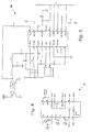
- Figure 6 is a circuit diagram showing several of the circuits leading from microcontroller 11.
- Read/write circuit 20 is shown to include antenna 21.
- Display screen 18 is also shown connected to microcontroller 11.
- microcontroller 11 contains programming to calculate and display the remaining filter life.
- the established or rated filter life is written into RFID tag 23, along with such information as filter type or name, manufacturer, and manufacturing lot number.
- microcontroller 11 reads and stores this information through read/write circuit 20 after powering RFID tag 23 through antenna 21 of read/write circuit 20. Some or all the information is displayed as seen in the screen shots of Figure 7 . Displayed calculations such as remaining filter life may be based on a simple calculation loop.
- Established filter life may be based on a particular evacuation motor speed or intake flow rate which is a function of evacuation motor speed. At a preset time interval, the motor speed or flow rate is sensed or calculated and recorded by the program in microcontroller 11.
- the number of minutes or seconds is subtracted from the rated filter life.
- a filter life for a particular filter is rated at 10 hours (600 minutes)
- remaining filter life would be 599 minutes.
- this calculation may be adjusted by the actual flow rate.
- the flow rate used to establish the rated filter life is 10 CFM
- a flow rate of 5 CFM would increase filter life to 20 hours which would be calculated and stored in microcontroller 11 memory and displayed.
- the actual flow rate is 20 CFM
- the actual filter life would be 300 minutes (5 hours).
- the displayed remaining filter life is based on the current operating flow rate.
- filter life may be based on time of use.
- microcontroller 11 and/or RFID tag 23 may include a clock or timer function to determine the length of time of filter use.
- Each recorded change in filter life is also transmitted through read/write circuit 20 to RFID tag 23 where it may be saved. Consequently, if filter 22 is moved from one evacuation unit to another compatible unit, that second unit would read the remaining filter life on the transferred filter.
- Remaining filter life may be displayed in several ways, including but not limited to, a percentage of rated filter life, actual remaining filter life, and consumed filter life.
- diagnostic parameters such as motor brush life and filter history, may be calculated and displayed using similar calculations.
- the microcontroller 11 and/or RFID tag 23 may also include a reset feature in which an evacuation system is powered into a standby or operational mode but no smoke or other particulates are actually evacuated through filter 22. In such a situation, a recorded filter life may be reset to the full rated life.
- Other possible displays include but are not limited to, error messages indicating filter or diagnostic errors, authentication codes, filter history, evacuation flow rate, suction speed, and/or motor speed. Some or all of these operational and structural parameters may be transmitted and saved onto RFID tag 23 or equivalent components.
- RFID tag 23 of filter 22 contains control information that when transmitted to microcontroller 11, details particular operational parameters to be enabled. For example, certain filters 22 may be designed for certain flow rates. Commands transmitted from RFID tag 23 may then be transmitted to microcontroller 11 to operate the evacuation motor at those specific flow rates or within a certain flow rate range.
Landscapes
- Physics & Mathematics (AREA)
- General Physics & Mathematics (AREA)
- Engineering & Computer Science (AREA)
- Automation & Control Theory (AREA)
- Filtering Of Dispersed Particles In Gases (AREA)
- Arrangements For Transmission Of Measured Signals (AREA)
- Cyclones (AREA)
- Respiratory Apparatuses And Protective Means (AREA)
- Feeding And Controlling Fuel (AREA)
Abstract
Description
-
WO 03/017015 -
US 6,636,151 describes a water dispenser comprising a filter and a system for determining when a filter needs to be replaced and indicating this fact. -
JP 2004 342510 -
WO 2005/098558 describes a system for detecting the absence or presence of components from a location. Each component can be provided with an RFID tag for use in detecting its presence or absence. -
EP 1 339 014 A - According to one aspect of the present invention there is provided a method as claimed in
claim 1. - According to another aspect of the present invention there is provided a system as claimed in
claim 5. -
-
Figure 1 is a schematic drawing of components of an embodiment of an evacuation system connected to the microcontroller; -
Figures 2 is a schematic drawing of one embodiment of a read/write circuit functionally connected to a filter; -
Figures 3 is a schematic drawing of another embodiment of a read/write circuit functionally connected to a filter; -
Figure 4 is a circuit diagram of a RS-232 communication circuit of an evacuation system; -
Figure 5 is a circuit diagram of a two way read/write circuit connected to a microcontroller of an evacuation system; -
Figure 6 is a circuit diagram showing a display panel and a two-way read/write circuit connected to a microcontroller of an evacuation system; and, -
Figure 7 illustrates screen shots displayed on a display panel of an evacuation system. - Initially, it should be appreciated that like drawing numbers on different drawing views identify identical structural elements. It also should be appreciated that figure proportions and angles are not always to scale. Further, it should be understood that the evacuation system is not limited to the disclosed embodiments. Various modifications and equivalent arrangements may be included within the scope of the appended claims.
- Referring to the drawings,
Figure 1 is a partial schematic drawing of anevacuation system 10 for evacuating suspended particulates from a fluid stream. It should be understood that the fluid stream may be comprised of liquids, gases, and/or solids. Further, the suspended particles may be visible or microscopic particles; organic or inorganic matter. In one embodiment, the suspended particles in a fluid stream are in the form of smoke.Evacuation system 10 includes at least one fluid intake, at least one exhaust outlet and an evacuation motor unit (not shown). As shown, amicrocontroller 11 is in functional communication with components ofevacuation system 10 such asinput signal latches 13,output signal latches 14, an alternate circuit (A/C)synchronization system 15, amotor drive 16 and aremote switch interface 17.Microcontroller 11 is also in functional communication with adisplay screen 18. In addition,microcontroller 11 is functionally connected to a two-way read/writecircuit 20. In the embodiment shown inFigure 1 , read/writecircuit 20 includes anantenna 21 which may be present if read/writecircuit 20 is a radio frequency identification tag ("RFID") reader/writer. The read/write circuit 20 may be based on the ISO 15693 standard for communicating with tags at 13.56 MHz. Further, the interface betweenmicrocontroller 11 and read/writecircuit 20 may include a 3-wire serial interface having a bi-directional clock controlled bymicrocontroller 11 during command/data write operations and by read/writecircuit 20 during data read operations. In one embodiment,evacuation system 10 includes a control panel (not shown). The control panel anddisplay screen 18 may combined into one integral component. In another embodiment,evacuation system 10 is in functional communication with afilter 22 which includes a second two-way read/write circuit such asRFID tag 23. - A suitable read/write circuit component is the TI S6700 ASIC from Texas Instruments or similarly equivalent devices. In an alternate embodiment, read/write
circuit 20 may include a direct-wired connection betweenmicrocontroller 11 and a downstream component, such asfilter 22. -
Microcontroller 11 contains at least one program configured to control the functionally connected components as well as, when necessary, determining changes in functional or operational parameters of the functionally connected components. As used herein the phrase "functionally connected" shall mean that components, for example,microcontroller 11 and read/writecircuit 20, are connected in such a way that signals, data, controls and other applicable modes of information are transmitted therebetween using either suitable direct wired connections or a form of wireless or radio transmission and reception. In one embodiment, in which read/writecircuit 20 is an RFID tag reader/writer, an antenna is used to functionally communicate with an RFID tag on another component.Microcontroller 11 may include an external electrically erasable programmable read-only memory (EEPROM) to hold the required programs. An internal EEPROM may be used as it requires fewer I/O pins and makes available more memory. In an alternate embodiment,microcontroller 11 may be in functional communication with a data port, such as a USB connection, to allow changes or replacement of a program. - In another alternate embodiment, read/write
circuit 20 and read/write circuit offilter 22 may transfer information using short-distance radio communication. According to this kind of radio communication method, cordless communication between equipment and a terminal can be established. For example, short-distance radio communication can be used for the following: data exchange between pieces of portable information equipment; and transmission of data and sound between a main body of a telephone (or a portable music player) and a headset, between a main phone and a cordless handset, and between others. One representative type of short-distance radio communication is Bluetooth. -
Figures 2 and 3 illustrate schematically two configurations of read/writecircuit 20 functionally connected tofilter 22 andRFID tag 23. InFigure 2 ,antenna 21 is arranged such that the planes formed byantenna 21 andRFID tag 23 are parallel to each other. Although this configuration allows for two-way communication between distances of up to 8 inches, the presence of metal or other conductive material betweenantenna 21 andtag 23 interferes with communication between the two components. -
Figure 3 illustrates an orientation in whichantenna 21 is looped around a filter housing (not shown) in a substantially perpendicular orientation in relation totag 23. While this orientation reduces effective communication range, it allows for designs such thattag 23 is about 0.5 inch from at least a part ofantenna 21. As shown inFigure 2 ,antenna 21 is arranged parallel to at least a part oftag 23. Suitable RFID tags include the TI-IT HF-I transponder family of tags from Texas Instruments. Persons of ordinary skill in the art will recognize the more than oneRFID tag 23 may be used withfilter 22. Also, the two-way read/write circuit offilter 22, such asRFID tag 23, can be used to transmit command and control instructions tomicrocontroller 11. -
Figure 7 is a collection of screen shots presented ondisplay screen 18, such as an LCD screen, to inform the system user of various operational or structural parameters or data including, but not limited to, type of filter used, filter life remaining, filter life consumed, evacuation motor suction setting, filter lot number, filter manufacturing date, authentication code(s), evacuation motor brush life, and an error message. It will be obvious to those skilled in the art that other messages, including set up parameters such as off/standby/on message(s), flow rate and/or motor speed, mode selection, and filter overuse (use past rated filter life) may be displayed on the display screen. An authentication code (for example, to allow or disallow operation of the evacuation system), first written into a filter read/write circuit, may be transmitted tomicrocontroller 11 to command that a certain flow rate or flow rate range be used for that filter. It will be recognized that the functional communication betweenRFID tag 23 offilter 22 andmicrocontroller 11 through read/writecircuit 20 enables the above operation and/or structural parameters to be transmitted to and fromfilter 22 andmicrocontroller 11. - Typically,
display screen 18 may be mounted on a evacuation boom in an easily visible position such as that disclosed inU.S. Patent No. 6,524,307 to Palmerton, et al . Alternatively,display screen 18 may be detached and mounted on a wall, in a separate control room, operating room or on a stand-alone evacuation unit that intakes air to filter smoke and/or particulate matter and evacuates it back into a room. In one embodiment,display screen 18 is integral with an evacuation system control panel. -
Figure 6 is a circuit diagram showing several of the circuits leading frommicrocontroller 11. Read/write circuit 20 is shown to includeantenna 21.Display screen 18 is also shown connected tomicrocontroller 11. - Typically,
microcontroller 11 contains programming to calculate and display the remaining filter life. The established or rated filter life is written intoRFID tag 23, along with such information as filter type or name, manufacturer, and manufacturing lot number. When a new filter is inserted into the evacuation system,microcontroller 11 reads and stores this information through read/write circuit 20 after poweringRFID tag 23 throughantenna 21 of read/write circuit 20. Some or all the information is displayed as seen in the screen shots ofFigure 7 . Displayed calculations such as remaining filter life may be based on a simple calculation loop. Established filter life may be based on a particular evacuation motor speed or intake flow rate which is a function of evacuation motor speed. At a preset time interval, the motor speed or flow rate is sensed or calculated and recorded by the program inmicrocontroller 11. In the same operation, the number of minutes or seconds is subtracted from the rated filter life. Thus, if a filter life for a particular filter is rated at 10 hours (600 minutes), after one minute of operation, remaining filter life would be 599 minutes. In one embodiment, this calculation may be adjusted by the actual flow rate. Thus, if the flow rate used to establish the rated filter life is 10 CFM, a flow rate of 5 CFM would increase filter life to 20 hours which would be calculated and stored inmicrocontroller 11 memory and displayed. Similarly, if the actual flow rate is 20 CFM, the actual filter life would be 300 minutes (5 hours). In one embodiment, if an evacuation system is operated at different flow rates, the displayed remaining filter life is based on the current operating flow rate. - In an alternate embodiment, filter life may be based on time of use. In this embodiment,
microcontroller 11 and/orRFID tag 23 may include a clock or timer function to determine the length of time of filter use. - Each recorded change in filter life is also transmitted through read/
write circuit 20 toRFID tag 23 where it may be saved. Consequently, iffilter 22 is moved from one evacuation unit to another compatible unit, that second unit would read the remaining filter life on the transferred filter. Remaining filter life may be displayed in several ways, including but not limited to, a percentage of rated filter life, actual remaining filter life, and consumed filter life. Similarly, diagnostic parameters, such as motor brush life and filter history, may be calculated and displayed using similar calculations. - The
microcontroller 11 and/orRFID tag 23 may also include a reset feature in which an evacuation system is powered into a standby or operational mode but no smoke or other particulates are actually evacuated throughfilter 22. In such a situation, a recorded filter life may be reset to the full rated life. Other possible displays include but are not limited to, error messages indicating filter or diagnostic errors, authentication codes, filter history, evacuation flow rate, suction speed, and/or motor speed. Some or all of these operational and structural parameters may be transmitted and saved ontoRFID tag 23 or equivalent components. - In one embodiment,
RFID tag 23 offilter 22 contains control information that when transmitted tomicrocontroller 11, details particular operational parameters to be enabled. For example,certain filters 22 may be designed for certain flow rates. Commands transmitted fromRFID tag 23 may then be transmitted tomicrocontroller 11 to operate the evacuation motor at those specific flow rates or within a certain flow rate range. - Up to this point, the evacuation system was described in detail with reference to specific embodiments. The described embodiments were presented in the form of exemplification and should not be interpreted in a limited manner. Changes and modifications to these embodiments should be readily apparent to those having ordinary skill in the art.
Claims (9)
- A method for controlling an evacuation system (10) for evacuating suspended particulates from a fluid having at least one fluid intake, at least one fluid outlet, an evacuation motor for transferring fluid from said at least on fluid intake to said at least one fluid outlet, a RFID tag reader/writer (20), a display screen (18), and a controller (11) coupled to said RFID tag reader/writer (20), said display and said evacuation motor, said method comprising:inserting a filter into said evacuation system, said filter (22) including a RFID tag (23) having information stored thereon, wherein the information is regarding characteristics of said filter;transmitting said information from said RFID tag (23) to said RFID tag reader/writer (20);interpreting said information with said controller (11);setting at least one operational parameter of said evacuation motor based on the interpreted information; anddisplaying said information with said display screen (18).
- The method according to claim 1 wherein said information stored on said RFID tag (23) represents filter type or filter life.
- The method according to claim 2 wherein said information stored on said RFID tag (23) represents filter life, and the method further comprises calculating changes in filter life with said controller and transmitting said changes in filter life to said RFID tag (23).
- The method according to any of the preceding claims wherein said at least one operational parameter is evacuation motor flow rate or evacuation motor on/off.
- A system (10) for evacuating suspended particulates from a fluid comprising:at least one fluid intake;at least one fluid outlet;an evacuation motor for transferring fluid from said at least one fluid intake to said at least one fluid outlet;a RFID tag reader/writer (20) for receiving information; !a filter (22) having a RFID tag (23) coupled thereto, said RFID tag (23) adapted to transmit information to said RFID tag reader/writer (20), wherein the information is regarding characteristics of said filter;a microcontroller (11) in functional communication with said RFID tag reader/writer (20) and said evacuation motor, wherein said microcontroller (11) interprets the information received by the RFID tag reader/writer (20) and controls at least one operational parameter of said evacuation motor based on said interpreted information; anda display screen (18) coupled to said microcontroller (11) for displaying said information.
- The evacuation system of claim 5 wherein said information is stored on said RFID tag (23) representing filter life and said microcontroller (11) is adapted to calculate changes in filter life and said RFID tag reader/writer (20) is adapted to transmit said calculated changes in filter life to said RFID tag (23).
- The evacuation system of claim 5 or claim 6 wherein said information regarding the characteristics of said filter is stored on said RFID tag, and said characteristics comprise at least one of:filter life,remaining filter life,consumed filter life,manufacturing history of said filter, anda filter overuse signal.
- The evacuation system of any of claims 5 to 7 wherein said at least one operational parameter is at least one of:evacuation motor speed,evacuation motor flow rate, andstandby/operational status.
- The evacuation system of any of claims 5 to 8 wherein said filter characteristic is an authentication code read and authenticated by said microcontroller, whereby said microcontroller acts to allow or disallow operation of said evacuation system based on said authentication code.
Applications Claiming Priority (2)
| Application Number | Priority Date | Filing Date | Title |
|---|---|---|---|
| US66812605P | 2005-04-04 | 2005-04-04 | |
| PCT/US2006/012517 WO2006107976A1 (en) | 2005-04-04 | 2006-04-04 | A fluid evacuation system with two-way communication filter |
Publications (2)
| Publication Number | Publication Date |
|---|---|
| EP1872182A1 EP1872182A1 (en) | 2008-01-02 |
| EP1872182B1 true EP1872182B1 (en) | 2011-08-03 |
Family
ID=36691598
Family Applications (1)
| Application Number | Title | Priority Date | Filing Date |
|---|---|---|---|
| EP06749261A Expired - Lifetime EP1872182B1 (en) | 2005-04-04 | 2006-04-04 | A fluid evacuation system with two-way communication filter |
Country Status (7)
| Country | Link |
|---|---|
| US (2) | US7761188B2 (en) |
| EP (1) | EP1872182B1 (en) |
| AT (1) | ATE519146T1 (en) |
| CA (1) | CA2541694C (en) |
| DK (1) | DK1872182T3 (en) |
| ES (1) | ES2370994T3 (en) |
| WO (1) | WO2006107976A1 (en) |
Families Citing this family (32)
| Publication number | Priority date | Publication date | Assignee | Title |
|---|---|---|---|---|
| US8021469B2 (en) * | 2005-07-14 | 2011-09-20 | Access Business Group International Llc | Control methods for an air treatment system |
| WO2007098540A1 (en) * | 2006-03-01 | 2007-09-07 | Resmed Ltd | Method and apparatus for reminding user to replace and/or service cpap apparatus and/or component thereof |
| EP1983642A1 (en) * | 2007-04-19 | 2008-10-22 | Siemens Aktiengesellschaft | Control unit for a motor starter |
| US20100273068A1 (en) * | 2009-04-22 | 2010-10-28 | Adaptive Materials, Inc. | Fuel cell system including a fuel filter member with a filter property indicator |
| US8882768B2 (en) | 2009-04-24 | 2014-11-11 | Megadyne Medical Products, Inc. | Hand piece with adjustable utility conduit |
| US8882767B2 (en) | 2009-04-24 | 2014-11-11 | Megadyne Medical Products, Inc. | Electrosurgical instrument with adjustable utility conduit |
| US20110189587A1 (en) * | 2010-02-01 | 2011-08-04 | Adaptive Materials, Inc. | Interconnect Member for Fuel Cell |
| WO2012044410A2 (en) * | 2010-09-20 | 2012-04-05 | Surgiquest, Inc. | Multi-flow filtration system |
| US8616205B2 (en) | 2010-10-06 | 2013-12-31 | Honeywell International Inc. | Respirator with end-of-service-life detection |
| US9079049B2 (en) | 2011-11-02 | 2015-07-14 | Honeywell International Inc. | Respirators with a sacrificial cartridge for end of service life indication |
| AU2012388657B2 (en) | 2012-08-28 | 2017-09-07 | Covidien Lp | Adjustable electrosurgical pencil |
| US9375253B2 (en) | 2013-03-14 | 2016-06-28 | Megadyne Medical Products, Inc. | Electrosurgical instrument |
| US9259260B2 (en) | 2013-03-14 | 2016-02-16 | Megadyne Medical Products, Inc. | Fluid evacuation device |
| USD709196S1 (en) | 2013-03-15 | 2014-07-15 | Megadyne Medical Products, Inc. | Hand piece |
| US9283411B2 (en) | 2013-04-19 | 2016-03-15 | Honeywell International Inc. | Gas sensing drift compensation using gas self-referencing for end of service life indication for respirators |
| CA2827695C (en) | 2013-09-20 | 2021-02-16 | Leonard Ineson | Adjustable electrosurgical pencil |
| WO2015057956A1 (en) * | 2013-10-16 | 2015-04-23 | Cummins Filtration Ip, Inc. | Electronic filter detection feature for liquid filtration systems |
| JP6527682B2 (en) * | 2014-08-08 | 2019-06-05 | ザッカリー ライスZachary Rice | Built-in water filtration system and method of using the same |
| US9815725B2 (en) | 2014-08-08 | 2017-11-14 | Multipure International | Self-contained water filtration system and method of using the same |
| US9783430B2 (en) | 2014-08-12 | 2017-10-10 | Multipure International | Self-contained water filtration system including wireless communication and filter verification and method of using the same |
| AU2016304995B2 (en) * | 2015-08-13 | 2021-10-21 | Bayer Healthcare Llc | Systems for determining, and devices for indicating, viable life of replaceable components thereof and methods therefor |
| CN205090507U (en) * | 2015-09-30 | 2016-03-16 | 飞利浦(中国)投资有限公司 | Air -purifying device |
| WO2017161530A1 (en) | 2016-03-24 | 2017-09-28 | 3M Innovative Properties Company | Room air purifier with rfid reader |
| US11191916B2 (en) | 2016-12-22 | 2021-12-07 | Ag Industries Llc | Filtration system |
| US11213773B2 (en) | 2017-03-06 | 2022-01-04 | Cummins Filtration Ip, Inc. | Genuine filter recognition with filter monitoring system |
| EP3596401A1 (en) | 2017-03-17 | 2020-01-22 | Aerobiotix, Inc. | System and method for maintaining, monitoring and/or improving air quality and purity in at least one room or environment |
| WO2019130124A1 (en) * | 2017-12-28 | 2019-07-04 | Ethicon Llc | Smoke evacuation system with a communication circuit for communication between a filter and a smoke evacuation device |
| CN111542890B (en) * | 2017-12-28 | 2024-05-24 | 爱惜康有限责任公司 | Surgical extraction system having communication circuitry for communication between filter and smoke evacuation device |
| US11547463B2 (en) | 2018-09-21 | 2023-01-10 | Covidien Lp | Smoke evacuation electrosurgical pencil with adjustable electrode and vent tube |
| US11596466B2 (en) | 2019-09-09 | 2023-03-07 | Covidien Lp | Surgical instrument with evacuation port and method |
| CN116528924B (en) | 2020-10-06 | 2026-06-30 | 拜耳医药保健有限责任公司 | Systems, methods, and computer program products for providing access to a fluid injection system |
| US11786647B1 (en) | 2022-01-31 | 2023-10-17 | Stryker Corporation | Medical waste collection systems, manifolds, and related methods |
Citations (1)
| Publication number | Priority date | Publication date | Assignee | Title |
|---|---|---|---|---|
| US6636151B2 (en) * | 2000-06-27 | 2003-10-21 | Oasis Corporation | Water dispensing station with communication system |
Family Cites Families (39)
| Publication number | Priority date | Publication date | Assignee | Title |
|---|---|---|---|---|
| DE26833C (en) * | J. GJERS in Mitfdlesbrough on Tees, York, England | Brick compensation chambers, ({j | ||
| DE84148C (en) * | ||||
| US3825004A (en) | 1972-09-13 | 1974-07-23 | Durden Enterprises Ltd | Disposable electrosurgical cautery |
| US3974833A (en) | 1973-03-19 | 1976-08-17 | Durden Iii John G | Disposable electrosurgical cautery having optional suction control feature |
| US3828780A (en) | 1973-03-26 | 1974-08-13 | Valleylab Inc | Combined electrocoagulator-suction instrument |
| US4562838A (en) | 1981-01-23 | 1986-01-07 | Walker William S | Electrosurgery instrument |
| US5085657A (en) | 1983-03-14 | 1992-02-04 | Ben Simhon Haim | Electrosurgical instrument |
| US5451223B1 (en) | 1983-03-14 | 1998-11-03 | Ben Simhon Haim | Electrosurgical instrument |
| US4735603A (en) | 1986-09-10 | 1988-04-05 | James H. Goodson | Laser smoke evacuation system and method |
| US5217457A (en) | 1990-03-15 | 1993-06-08 | Valleylab Inc. | Enhanced electrosurgical apparatus |
| US5133714A (en) | 1991-05-06 | 1992-07-28 | Kirwan Surgical Products, Inc. | Electrosurgical suction coagulator |
| US5192424A (en) | 1991-12-05 | 1993-03-09 | Isp Investments Inc. | Filter identification device |
| US5354979A (en) | 1992-03-24 | 1994-10-11 | Alexander Adelson | Method and device for storing data |
| US5693044A (en) | 1992-12-11 | 1997-12-02 | Cosmescu; Ioan | Telescopic surgical device and method therefor |
| NL9300554A (en) | 1993-03-29 | 1994-10-17 | Doctro A V V | Assembly of filter device and a replaceable filter; as well as filter device and filter for use therein. |
| US5451222A (en) | 1994-03-16 | 1995-09-19 | Desentech, Inc. | Smoke evacuation system |
| US5674219A (en) | 1994-10-06 | 1997-10-07 | Donaldson Company, Inc. | Electrosurgical smoke evacuator |
| USD384148S (en) | 1996-03-18 | 1997-09-23 | Donaldson Company, Inc. | Smoke evacuator for an electrocautery scalpel |
| US6045596A (en) * | 1997-04-07 | 2000-04-04 | Medtek Devices, Inc. | Filter system to remove a contaminant from a fluid stream |
| KR100271768B1 (en) * | 1998-06-26 | 2001-02-01 | 윤종용 | Solvent composition for removing semiconductor photoresist, rework method of wafer for semiconductor device manufacturing and method for manufacturing semiconductor device using same |
| US6146353A (en) | 1998-09-22 | 2000-11-14 | Sherwood Services Ag | Smoke extraction device |
| DE19844631A1 (en) | 1998-09-29 | 2000-04-06 | Gantner Electronic Gmbh Schrun | System for monitoring, controlling, tracking and handling objects |
| US6558444B1 (en) * | 1998-12-03 | 2003-05-06 | Psi Global Ltd. | Fluid filters having a concealed machine-readable identification |
| USD426833S (en) | 1999-10-26 | 2000-06-20 | John Vanelli | Medical information card reader |
| US6879876B2 (en) | 2001-06-13 | 2005-04-12 | Advanced Technology Materials, Inc. | Liquid handling system with electronic information storage |
| WO2003017015A1 (en) * | 2001-07-31 | 2003-02-27 | Voith Turbo Gmbh & Co. Kg | Method for identifying modules or modular units and system for identifying and/or diagnosing a module or a modular unit comprising a plurality of individual components |
| US6524307B1 (en) | 2001-10-05 | 2003-02-25 | Medtek Devices, Inc. | Smoke evacuation apparatus |
| EP1507578A1 (en) | 2002-02-15 | 2005-02-23 | Cuno Incorporated | System for monitoring the performance of fluid treatment cartridges |
| US7638042B2 (en) * | 2002-02-15 | 2009-12-29 | 3M Innovative Properties Company | System for monitoring the performance of fluid treatment cartridges |
| JP2003242469A (en) | 2002-02-21 | 2003-08-29 | Daishowa Seiki Co Ltd | Information carrier |
| US20050209547A1 (en) | 2002-06-06 | 2005-09-22 | Burbank Jeffrey H | Last-chance quality check and/or air/pathogen filter for infusion systems |
| JP2004342510A (en) * | 2003-05-16 | 2004-12-02 | Sekisui Chem Co Ltd | Cogeneration system |
| US7597731B2 (en) | 2003-09-15 | 2009-10-06 | Medtek Devices, Inc. | Operating room smoke evacuator with integrated vacuum motor and filter |
| US7361155B2 (en) * | 2003-09-16 | 2008-04-22 | Therafuse, Inc. | Compensating liquid delivery system and method |
| US7481917B2 (en) | 2004-03-05 | 2009-01-27 | Hydranautics | Filtration devices with embedded radio frequency identification (RFID) tags |
| AU2005223452B2 (en) * | 2004-03-16 | 2008-05-15 | Newage Industries, Inc. | Process equipment tracking system |
| US20050224577A1 (en) * | 2004-04-08 | 2005-10-13 | Rozenblat Gary D | Method and apparatus for automated identifying, monitoring the use of, and assessing the effective life span of process manufacturing components |
| CA2464014A1 (en) * | 2004-04-08 | 2005-10-08 | Unknown | Closed-loop reel setup verification and traceability |
| US8007568B2 (en) * | 2006-04-12 | 2011-08-30 | Millipore Corporation | Filter with memory, communication and pressure sensor |
-
2006
- 2006-04-04 WO PCT/US2006/012517 patent/WO2006107976A1/en not_active Ceased
- 2006-04-04 ES ES06749261T patent/ES2370994T3/en not_active Expired - Lifetime
- 2006-04-04 AT AT06749261T patent/ATE519146T1/en not_active IP Right Cessation
- 2006-04-04 US US11/398,285 patent/US7761188B2/en active Active
- 2006-04-04 DK DK06749261.1T patent/DK1872182T3/en active
- 2006-04-04 CA CA2541694A patent/CA2541694C/en not_active Expired - Lifetime
- 2006-04-04 EP EP06749261A patent/EP1872182B1/en not_active Expired - Lifetime
-
2010
- 2010-06-08 US US12/796,292 patent/US8095241B2/en not_active Expired - Lifetime
Patent Citations (1)
| Publication number | Priority date | Publication date | Assignee | Title |
|---|---|---|---|---|
| US6636151B2 (en) * | 2000-06-27 | 2003-10-21 | Oasis Corporation | Water dispensing station with communication system |
Also Published As
| Publication number | Publication date |
|---|---|
| US20060265149A1 (en) | 2006-11-23 |
| US8095241B2 (en) | 2012-01-10 |
| US7761188B2 (en) | 2010-07-20 |
| CA2541694C (en) | 2011-07-05 |
| EP1872182A1 (en) | 2008-01-02 |
| US20100312402A1 (en) | 2010-12-09 |
| ATE519146T1 (en) | 2011-08-15 |
| ES2370994T3 (en) | 2011-12-26 |
| CA2541694A1 (en) | 2006-10-04 |
| WO2006107976A1 (en) | 2006-10-12 |
| DK1872182T3 (en) | 2011-11-14 |
Similar Documents
| Publication | Publication Date | Title |
|---|---|---|
| CA2541694C (en) | A fluid evacuation system with two-way communication filter | |
| US7317404B2 (en) | Method and apparatus for collecting and displaying consumption data from a meter reading system | |
| EP3279581B1 (en) | Remote control for air conditioner and air conditioner provided with same | |
| WO2018124291A1 (en) | Water purifier, water purifier system, water purifier management system, and method for detecting water purifier usage state | |
| KR101390201B1 (en) | Remote control system for dust collector | |
| CN104423301A (en) | Home appliance, home appliance system, and control method thereof | |
| US20140308896A1 (en) | Method as Well as System for Wireless Data Transmission | |
| WO2005104739A2 (en) | Rfid reader/writer device | |
| JP2012149855A (en) | Air conditioner | |
| CN104950788A (en) | Ration loading control system and ration loading instrument | |
| JP4939790B2 (en) | Game machine | |
| EP1930042B1 (en) | Apparatus having a water trap of detectable form, and method | |
| KR100513934B1 (en) | wireless remote detector and wireless remote detecting system thereof | |
| EP2413213B1 (en) | Field device | |
| JP2010097390A (en) | Data rewriting system | |
| JP4288928B2 (en) | Air conditioner | |
| JP2001147144A (en) | Communication system for flow meter and meter reading data | |
| JP7398333B2 (en) | Pump device management device, pump device, display method, and management method | |
| JP2008033841A (en) | Gas equipment or disaster prevention / crime prevention equipment, wireless unit, and portable terminal device | |
| EP2728796A2 (en) | Control method for a domestic device using a control kit, and control method for a water purifier using a control kit | |
| CN219551600U (en) | Gas meter | |
| CN101630423A (en) | Massage armchair remote management system | |
| KR100545500B1 (en) | Ultra-low power tap water meter and method | |
| JP2004150921A (en) | Gas meter device | |
| KR200309095Y1 (en) | Ultra-low-power wireless water supply meter |
Legal Events
| Date | Code | Title | Description |
|---|---|---|---|
| PUAI | Public reference made under article 153(3) epc to a published international application that has entered the european phase |
Free format text: ORIGINAL CODE: 0009012 |
|
| 17P | Request for examination filed |
Effective date: 20071031 |
|
| AK | Designated contracting states |
Kind code of ref document: A1 Designated state(s): AT BE BG CH CY CZ DE DK EE ES FI FR GB GR HU IE IS IT LI LT LU LV MC NL PL PT RO SE SI SK TR |
|
| 17Q | First examination report despatched |
Effective date: 20080303 |
|
| DAX | Request for extension of the european patent (deleted) | ||
| GRAP | Despatch of communication of intention to grant a patent |
Free format text: ORIGINAL CODE: EPIDOSNIGR1 |
|
| GRAS | Grant fee paid |
Free format text: ORIGINAL CODE: EPIDOSNIGR3 |
|
| GRAA | (expected) grant |
Free format text: ORIGINAL CODE: 0009210 |
|
| AK | Designated contracting states |
Kind code of ref document: B1 Designated state(s): AT BE BG CH CY CZ DE DK EE ES FI FR GB GR HU IE IS IT LI LT LU LV MC NL PL PT RO SE SI SK TR |
|
| REG | Reference to a national code |
Ref country code: GB Ref legal event code: FG4D |
|
| REG | Reference to a national code |
Ref country code: CH Ref legal event code: EP |
|
| REG | Reference to a national code |
Ref country code: IE Ref legal event code: FG4D |
|
| REG | Reference to a national code |
Ref country code: DE Ref legal event code: R096 Ref document number: 602006023515 Country of ref document: DE Effective date: 20110929 |
|
| REG | Reference to a national code |
Ref country code: DK Ref legal event code: T3 |
|
| REG | Reference to a national code |
Ref country code: NL Ref legal event code: VDEP Effective date: 20110803 |
|
| REG | Reference to a national code |
Ref country code: ES Ref legal event code: FG2A Ref document number: 2370994 Country of ref document: ES Kind code of ref document: T3 Effective date: 20111226 |
|
| LTIE | Lt: invalidation of european patent or patent extension |
Effective date: 20110803 |
|
| PG25 | Lapsed in a contracting state [announced via postgrant information from national office to epo] |
Ref country code: FI Free format text: LAPSE BECAUSE OF FAILURE TO SUBMIT A TRANSLATION OF THE DESCRIPTION OR TO PAY THE FEE WITHIN THE PRESCRIBED TIME-LIMIT Effective date: 20110803 Ref country code: LT Free format text: LAPSE BECAUSE OF FAILURE TO SUBMIT A TRANSLATION OF THE DESCRIPTION OR TO PAY THE FEE WITHIN THE PRESCRIBED TIME-LIMIT Effective date: 20110803 Ref country code: PT Free format text: LAPSE BECAUSE OF FAILURE TO SUBMIT A TRANSLATION OF THE DESCRIPTION OR TO PAY THE FEE WITHIN THE PRESCRIBED TIME-LIMIT Effective date: 20111205 Ref country code: IS Free format text: LAPSE BECAUSE OF FAILURE TO SUBMIT A TRANSLATION OF THE DESCRIPTION OR TO PAY THE FEE WITHIN THE PRESCRIBED TIME-LIMIT Effective date: 20111203 Ref country code: SE Free format text: LAPSE BECAUSE OF FAILURE TO SUBMIT A TRANSLATION OF THE DESCRIPTION OR TO PAY THE FEE WITHIN THE PRESCRIBED TIME-LIMIT Effective date: 20110803 Ref country code: NL Free format text: LAPSE BECAUSE OF FAILURE TO SUBMIT A TRANSLATION OF THE DESCRIPTION OR TO PAY THE FEE WITHIN THE PRESCRIBED TIME-LIMIT Effective date: 20110803 |
|
| REG | Reference to a national code |
Ref country code: AT Ref legal event code: MK05 Ref document number: 519146 Country of ref document: AT Kind code of ref document: T Effective date: 20110803 |
|
| PG25 | Lapsed in a contracting state [announced via postgrant information from national office to epo] |
Ref country code: LV Free format text: LAPSE BECAUSE OF FAILURE TO SUBMIT A TRANSLATION OF THE DESCRIPTION OR TO PAY THE FEE WITHIN THE PRESCRIBED TIME-LIMIT Effective date: 20110803 Ref country code: AT Free format text: LAPSE BECAUSE OF FAILURE TO SUBMIT A TRANSLATION OF THE DESCRIPTION OR TO PAY THE FEE WITHIN THE PRESCRIBED TIME-LIMIT Effective date: 20110803 Ref country code: PL Free format text: LAPSE BECAUSE OF FAILURE TO SUBMIT A TRANSLATION OF THE DESCRIPTION OR TO PAY THE FEE WITHIN THE PRESCRIBED TIME-LIMIT Effective date: 20110803 Ref country code: GR Free format text: LAPSE BECAUSE OF FAILURE TO SUBMIT A TRANSLATION OF THE DESCRIPTION OR TO PAY THE FEE WITHIN THE PRESCRIBED TIME-LIMIT Effective date: 20111104 Ref country code: SI Free format text: LAPSE BECAUSE OF FAILURE TO SUBMIT A TRANSLATION OF THE DESCRIPTION OR TO PAY THE FEE WITHIN THE PRESCRIBED TIME-LIMIT Effective date: 20110803 Ref country code: CY Free format text: LAPSE BECAUSE OF FAILURE TO SUBMIT A TRANSLATION OF THE DESCRIPTION OR TO PAY THE FEE WITHIN THE PRESCRIBED TIME-LIMIT Effective date: 20110803 |
|
| PG25 | Lapsed in a contracting state [announced via postgrant information from national office to epo] |
Ref country code: BE Free format text: LAPSE BECAUSE OF FAILURE TO SUBMIT A TRANSLATION OF THE DESCRIPTION OR TO PAY THE FEE WITHIN THE PRESCRIBED TIME-LIMIT Effective date: 20110803 |
|
| PG25 | Lapsed in a contracting state [announced via postgrant information from national office to epo] |
Ref country code: SK Free format text: LAPSE BECAUSE OF FAILURE TO SUBMIT A TRANSLATION OF THE DESCRIPTION OR TO PAY THE FEE WITHIN THE PRESCRIBED TIME-LIMIT Effective date: 20110803 Ref country code: CZ Free format text: LAPSE BECAUSE OF FAILURE TO SUBMIT A TRANSLATION OF THE DESCRIPTION OR TO PAY THE FEE WITHIN THE PRESCRIBED TIME-LIMIT Effective date: 20110803 |
|
| PG25 | Lapsed in a contracting state [announced via postgrant information from national office to epo] |
Ref country code: RO Free format text: LAPSE BECAUSE OF FAILURE TO SUBMIT A TRANSLATION OF THE DESCRIPTION OR TO PAY THE FEE WITHIN THE PRESCRIBED TIME-LIMIT Effective date: 20110803 Ref country code: EE Free format text: LAPSE BECAUSE OF FAILURE TO SUBMIT A TRANSLATION OF THE DESCRIPTION OR TO PAY THE FEE WITHIN THE PRESCRIBED TIME-LIMIT Effective date: 20110803 |
|
| PLBE | No opposition filed within time limit |
Free format text: ORIGINAL CODE: 0009261 |
|
| STAA | Information on the status of an ep patent application or granted ep patent |
Free format text: STATUS: NO OPPOSITION FILED WITHIN TIME LIMIT |
|
| 26N | No opposition filed |
Effective date: 20120504 |
|
| REG | Reference to a national code |
Ref country code: DE Ref legal event code: R097 Ref document number: 602006023515 Country of ref document: DE Effective date: 20120504 |
|
| PG25 | Lapsed in a contracting state [announced via postgrant information from national office to epo] |
Ref country code: MC Free format text: LAPSE BECAUSE OF NON-PAYMENT OF DUE FEES Effective date: 20120430 |
|
| REG | Reference to a national code |
Ref country code: CH Ref legal event code: PL |
|
| REG | Reference to a national code |
Ref country code: IE Ref legal event code: MM4A |
|
| PG25 | Lapsed in a contracting state [announced via postgrant information from national office to epo] |
Ref country code: IE Free format text: LAPSE BECAUSE OF NON-PAYMENT OF DUE FEES Effective date: 20120404 Ref country code: CH Free format text: LAPSE BECAUSE OF NON-PAYMENT OF DUE FEES Effective date: 20120430 Ref country code: LI Free format text: LAPSE BECAUSE OF NON-PAYMENT OF DUE FEES Effective date: 20120430 |
|
| PG25 | Lapsed in a contracting state [announced via postgrant information from national office to epo] |
Ref country code: BG Free format text: LAPSE BECAUSE OF FAILURE TO SUBMIT A TRANSLATION OF THE DESCRIPTION OR TO PAY THE FEE WITHIN THE PRESCRIBED TIME-LIMIT Effective date: 20111103 |
|
| REG | Reference to a national code |
Ref country code: DE Ref legal event code: R082 Ref document number: 602006023515 Country of ref document: DE Representative=s name: BOCKHORNI & KOLLEGEN PATENT- UND RECHTSANWAELT, DE Ref country code: DE Ref legal event code: R082 Ref document number: 602006023515 Country of ref document: DE Representative=s name: HEYER, VOLKER, DIPL.-PHYS. DR.RER.NAT., DE |
|
| PG25 | Lapsed in a contracting state [announced via postgrant information from national office to epo] |
Ref country code: TR Free format text: LAPSE BECAUSE OF FAILURE TO SUBMIT A TRANSLATION OF THE DESCRIPTION OR TO PAY THE FEE WITHIN THE PRESCRIBED TIME-LIMIT Effective date: 20110803 |
|
| REG | Reference to a national code |
Ref country code: DE Ref legal event code: R082 Ref document number: 602006023515 Country of ref document: DE Representative=s name: HEYER, VOLKER, DIPL.-PHYS. DR.RER.NAT., DE |
|
| PG25 | Lapsed in a contracting state [announced via postgrant information from national office to epo] |
Ref country code: LU Free format text: LAPSE BECAUSE OF NON-PAYMENT OF DUE FEES Effective date: 20120404 |
|
| PG25 | Lapsed in a contracting state [announced via postgrant information from national office to epo] |
Ref country code: HU Free format text: LAPSE BECAUSE OF FAILURE TO SUBMIT A TRANSLATION OF THE DESCRIPTION OR TO PAY THE FEE WITHIN THE PRESCRIBED TIME-LIMIT Effective date: 20060404 |
|
| REG | Reference to a national code |
Ref country code: FR Ref legal event code: PLFP Year of fee payment: 11 |
|
| REG | Reference to a national code |
Ref country code: FR Ref legal event code: PLFP Year of fee payment: 12 |
|
| REG | Reference to a national code |
Ref country code: FR Ref legal event code: PLFP Year of fee payment: 13 |
|
| PGFP | Annual fee paid to national office [announced via postgrant information from national office to epo] |
Ref country code: GB Payment date: 20240429 Year of fee payment: 19 |
|
| PGFP | Annual fee paid to national office [announced via postgrant information from national office to epo] |
Ref country code: DE Payment date: 20240429 Year of fee payment: 19 |
|
| PGFP | Annual fee paid to national office [announced via postgrant information from national office to epo] |
Ref country code: DK Payment date: 20240425 Year of fee payment: 19 |
|
| PGFP | Annual fee paid to national office [announced via postgrant information from national office to epo] |
Ref country code: ES Payment date: 20240503 Year of fee payment: 19 |
|
| PGFP | Annual fee paid to national office [announced via postgrant information from national office to epo] |
Ref country code: IT Payment date: 20240422 Year of fee payment: 19 Ref country code: FR Payment date: 20240425 Year of fee payment: 19 |
|
| REG | Reference to a national code |
Ref country code: DE Ref legal event code: R119 Ref document number: 602006023515 Country of ref document: DE |
|
| REG | Reference to a national code |
Ref country code: DK Ref legal event code: EBP Effective date: 20250430 |
|
| GBPC | Gb: european patent ceased through non-payment of renewal fee |
Effective date: 20250404 |
|
| PG25 | Lapsed in a contracting state [announced via postgrant information from national office to epo] |
Ref country code: DE Free format text: LAPSE BECAUSE OF NON-PAYMENT OF DUE FEES Effective date: 20251104 |
|
| PG25 | Lapsed in a contracting state [announced via postgrant information from national office to epo] |
Ref country code: GB Free format text: LAPSE BECAUSE OF NON-PAYMENT OF DUE FEES Effective date: 20250404 |
|
| PG25 | Lapsed in a contracting state [announced via postgrant information from national office to epo] |
Ref country code: FR Free format text: LAPSE BECAUSE OF NON-PAYMENT OF DUE FEES Effective date: 20250430 |
|
| PG25 | Lapsed in a contracting state [announced via postgrant information from national office to epo] |
Ref country code: DK Free format text: LAPSE BECAUSE OF NON-PAYMENT OF DUE FEES Effective date: 20250430 |
|
| PG25 | Lapsed in a contracting state [announced via postgrant information from national office to epo] |
Ref country code: IT Free format text: LAPSE BECAUSE OF NON-PAYMENT OF DUE FEES Effective date: 20250404 |
|
| REG | Reference to a national code |
Ref country code: ES Ref legal event code: FD2A Effective date: 20260526 |
|
| PG25 | Lapsed in a contracting state [announced via postgrant information from national office to epo] |
Ref country code: ES Free format text: LAPSE BECAUSE OF NON-PAYMENT OF DUE FEES Effective date: 20250405 |