EP1871210B1 - A method of determining the degree of filling of the dust collector of a vacuum cleaner and a filling indicator - Google Patents
A method of determining the degree of filling of the dust collector of a vacuum cleaner and a filling indicator Download PDFInfo
- Publication number
- EP1871210B1 EP1871210B1 EP06706100A EP06706100A EP1871210B1 EP 1871210 B1 EP1871210 B1 EP 1871210B1 EP 06706100 A EP06706100 A EP 06706100A EP 06706100 A EP06706100 A EP 06706100A EP 1871210 B1 EP1871210 B1 EP 1871210B1
- Authority
- EP
- European Patent Office
- Prior art keywords
- dust collector
- connecting stub
- filling
- vacuum cleaner
- differential pressure
- Prior art date
- Legal status (The legal status is an assumption and is not a legal conclusion. Google has not performed a legal analysis and makes no representation as to the accuracy of the status listed.)
- Expired - Lifetime
Links
Images
Classifications
-
- A—HUMAN NECESSITIES
- A47—FURNITURE; DOMESTIC ARTICLES OR APPLIANCES; COFFEE MILLS; SPICE MILLS; SUCTION CLEANERS IN GENERAL
- A47L—DOMESTIC WASHING OR CLEANING; SUCTION CLEANERS IN GENERAL
- A47L9/00—Details or accessories of suction cleaners, e.g. mechanical means for controlling the suction or for effecting pulsating action; Storing devices specially adapted to suction cleaners or parts thereof; Carrying-vehicles specially adapted for suction cleaners
- A47L9/28—Installation of the electric equipment, e.g. adaptation or attachment to the suction cleaner; Controlling suction cleaners by electric means
- A47L9/2857—User input or output elements for control, e.g. buttons, switches or displays
-
- A—HUMAN NECESSITIES
- A47—FURNITURE; DOMESTIC ARTICLES OR APPLIANCES; COFFEE MILLS; SPICE MILLS; SUCTION CLEANERS IN GENERAL
- A47L—DOMESTIC WASHING OR CLEANING; SUCTION CLEANERS IN GENERAL
- A47L9/00—Details or accessories of suction cleaners, e.g. mechanical means for controlling the suction or for effecting pulsating action; Storing devices specially adapted to suction cleaners or parts thereof; Carrying-vehicles specially adapted for suction cleaners
- A47L9/10—Filters; Dust separators; Dust removal; Automatic exchange of filters
- A47L9/19—Means for monitoring filtering operation
-
- A—HUMAN NECESSITIES
- A47—FURNITURE; DOMESTIC ARTICLES OR APPLIANCES; COFFEE MILLS; SPICE MILLS; SUCTION CLEANERS IN GENERAL
- A47L—DOMESTIC WASHING OR CLEANING; SUCTION CLEANERS IN GENERAL
- A47L9/00—Details or accessories of suction cleaners, e.g. mechanical means for controlling the suction or for effecting pulsating action; Storing devices specially adapted to suction cleaners or parts thereof; Carrying-vehicles specially adapted for suction cleaners
- A47L9/28—Installation of the electric equipment, e.g. adaptation or attachment to the suction cleaner; Controlling suction cleaners by electric means
- A47L9/2805—Parameters or conditions being sensed
- A47L9/2821—Pressure, vacuum level or airflow
-
- A—HUMAN NECESSITIES
- A47—FURNITURE; DOMESTIC ARTICLES OR APPLIANCES; COFFEE MILLS; SPICE MILLS; SUCTION CLEANERS IN GENERAL
- A47L—DOMESTIC WASHING OR CLEANING; SUCTION CLEANERS IN GENERAL
- A47L9/00—Details or accessories of suction cleaners, e.g. mechanical means for controlling the suction or for effecting pulsating action; Storing devices specially adapted to suction cleaners or parts thereof; Carrying-vehicles specially adapted for suction cleaners
- A47L9/28—Installation of the electric equipment, e.g. adaptation or attachment to the suction cleaner; Controlling suction cleaners by electric means
- A47L9/2836—Installation of the electric equipment, e.g. adaptation or attachment to the suction cleaner; Controlling suction cleaners by electric means characterised by the parts which are controlled
- A47L9/2842—Suction motors or blowers
Definitions
- the invention relates to a method of determining the degree of filling of the dust collector of a vacuum cleaner, said vacuum cleaner having a compartment for receiving the dust collector, said compartment having a connecting stub for receiving a vacuum cleaner hose, wherein a differential pressure between an area inside the compartment, but outside the bag, and an area inside the bag is measured.
- the invention moreover relates to a filling indicator for determining the degree of filling of a dust collector, which is arranged in a compartment in the vacuum cleaner, said vacuum cleaner being connected with a connecting stub, wherein the degree of filling of the dust collector is determined by a differential pressure meter at two measurement positions, where the one measurement position is positioned inside the compartment outside the bag, while the other measurement position is positioned inside the bag.
- US Patent No. 4 733 431 discloses a vacuum cleaner which has three differential pressure meters to measure whether a bag is perhaps missing in the vacuum cleaner, or whether the bag has been filled or clogged in another manner, or whether there is an obstruction between the mouthpiece of the vacuum cleaner and forwards to the connecting stub of the vacuum cleaner hose.
- EP - 0 615 718 also discloses such a vacuum cleaner and forms the basis for the preambles of the independent claims.
- Measurement of the obstruction between the mouthpiece, the vacuum cleaner hose and the connecting stub is performed by means of a differential pressure measurement, where a pressure difference is measured between the pressure of the surrounding air outside the vacuum cleaner (the atmosphere) and the pressure at the outlet of the connecting stub near the inlet to the dust collector.
- DE 43 23 222 describes a method of measuring the degree of filling of a vacuum cleaner bag, wherein two differential pressure measurements are performed. These differential pressure measurements provide their respective indications of the composition of sucked material, so as to allow it to be determined more precisely whether the vacuum cleaner bag is about to be clogged, no matter whether it is by fine dust or coarser, airy material.
- an object of the invention is to provide a method and a filling indicator, where, in good time, a signal is emitted if there is a risk that material will accumulate in the connecting stub.
- the object of the invention is achieved by a method of the type defined in the introductory portion of claim 1, which is characterized in that a further differential pressure is measured between a first area and a second area in the connecting stub.
- the one area is disposed near the end of the connecting stub where it is passed into the dust collector, and the other area is disposed at a suitable distance inside the connecting stub relative to the said end of the connecting stub.
- the invention also relates to a filling indicator.
- This filling indicator is characterized in that a differential pressure meter with two measurement positions is additionally provided, where both measurement positions are positioned inside the connecting stub.
- the one measurement position is positioned in the connecting stub near the end of the connecting stub where it is passed into the dust collector, while the other measurement position is positioned at a distance from the one measurement position.
- a pipe is arranged axially with the connecting stub, said pipe extending at its one end from the end of the connecting stub where it is passed into the dust collector, and being connected at its other end by a transverse pipe member, and, as stated in claim 7, that a transverse pipe member is additionally arranged in the connecting stub at a distance from the end where the connecting stub is passed into the dust collector.
- an expedient length of the axial pipe is that the length of the axial pipe is at least 5 mm, preferably 50 mm, as stated in claim 8.
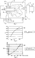
- the numeral 1 generally designates a vacuum cleaner shown schematically.
- the vacuum cleaner 1 is driven by a motor 2 and a blower 3 which provides a flow of air flowing from a vacuum cleaner hose (not shown) in the direction of the arrow 14 into the compartment 4 of the vacuum cleaner, in which a dust collector 15 is arranged, said dust collector being secured to a connection arrangement (not shown in detail) which is adapted to receive a plate 17 which forms part of the dust collector, as is well-known.
- the term dust collector is taken to mean a vacuum cleaner bag, a dust compartment without a bag, a drop chamber, a part of a cyclone separating system or the like.
- the dust collector may be fitted in the vacuum cleaner itself or be arranged somewhere in the hose system.
- the vacuum cleaner hose (not shown) is connected with a connecting stub 6, through which blast air is conveyed into the dust collector and further out into the compartment in the direction of the arrow 13.
- a pipe is arranged in the connecting stub 6 axially therewith, said pipe extending in the entire length of the connecting stub.
- the axial pipe is connected with a shorter, transverse pipe 8 at the inlet to the connecting stub.
- a further transverse pipe 9 is arranged in the connecting stub 6.
- a pipe 10 is arranged in one of the walls of the compartment.
- the numerals 11 and 12 designate differential pressure meters.
- the one differential pressure meter is connected with the two transverse pipes 8, 9 and is thus capable of measuring the pressure difference between the outlet of the connecting stub close to the dust collector and the inlet of the connecting stub.
- the other differential pressure meter is connected with the transverse pipe 9 and the pipe 10 in the wall of the compartment and is capable of measuring the pressure difference between the inlet of the connecting stub and the pressure inside the compartment 4.
- Fig. 2 shows typical values of P p along the Y-axis in dependence on the power fed to the motor of the vacuum cleaner and with a given degree of filling and composition of dust in the dust collector.
- the curve will change as the contents of the dust collector change, since it will be shifted to the left in fig. 2 with a greater degree of filling.
- the numeral 16 designates a slightly larger particle, e.g. a popcorn or another similar disturbance.
- a slightly larger particle e.g. a popcorn or another similar disturbance.
- several of these particles may be present in the dust collector. This particle will not contribute noticeably to the pressure drop which is measured with the differential pressure meter 12, as the resistance to the passage of air between the particles is not very great.
- the numeral 19 designates a curve where there is virtually no pressure drop in the connecting stub, irrespective of the power applied to the vacuum cleaner.
- the pressure conditions will follow the curve 20 in fig. 3 , which shows a clearly increased differential pressure at given power feeds to the motor.
- the differential pressure will change from about 250 Pa to 1800 Pa, which may be utilized for activating an indicator (not shown), which indicates that the dust collector is to be replaced.
- the vacuum cleaner is provided with an empty dust collector and is fed with 1200 W, which gives the following values over the pressure indicator 11: a) Pressure difference without object: 220 Pa b) Pressure difference with object: 2100 Pa
- the vacuum cleaner is provided with an empty dust collector, and the power is regulated down from 1200 W to 600 W, which gives the following values over the pressure indicator 11: a) Pressure difference without object: 90 Pa b) Pressure difference with object: 1380 Pa
- the vacuum cleaner is provided with an almost filled dust collector and is fed with 1200 W, which gives the following values over the pressure indicator 11: a) Pressure difference without object: 30 Pa b) Pressure difference with object: 450 Pa
- the vacuum cleaner is provided with an almost filled dust collector, and the power is regulated down from 1200 W to 600 W, which gives the following values over the pressure indicator 11: a) Pressure difference without object: 5 Pa b) Pressure difference with object: 5 Pa
- the pressure indicator does not work with a completely filled dust collector and half power feed, which, however, in the normal use of a vacuum cleaner is a power feed which hardly occurs in such a case.
- the invention thus provides the possibility of indicating whether a dust collector is to be replaced, irrespective of which material is present in the dust collector, as the degree of filling is determined by differential pressure meters which measure at high differential pressures, such as about 8000 Pa, and at low differential pressures, such as 2000 Pa.
Landscapes
- Engineering & Computer Science (AREA)
- Mechanical Engineering (AREA)
- Filters For Electric Vacuum Cleaners (AREA)
Abstract
Description
- The invention relates to a method of determining the degree of filling of the dust collector of a vacuum cleaner, said vacuum cleaner having a compartment for receiving the dust collector, said compartment having a connecting stub for receiving a vacuum cleaner hose, wherein a differential pressure between an area inside the compartment, but outside the bag, and an area inside the bag is measured.
- The invention moreover relates to a filling indicator for determining the degree of filling of a dust collector, which is arranged in a compartment in the vacuum cleaner, said vacuum cleaner being connected with a connecting stub, wherein the degree of filling of the dust collector is determined by a differential pressure meter at two measurement positions, where the one measurement position is positioned inside the compartment outside the bag, while the other measurement position is positioned inside the bag.
-
US Patent No. 4 733 431 discloses a vacuum cleaner which has three differential pressure meters to measure whether a bag is perhaps missing in the vacuum cleaner, or whether the bag has been filled or clogged in another manner, or whether there is an obstruction between the mouthpiece of the vacuum cleaner and forwards to the connecting stub of the vacuum cleaner hose. -
EP - 0 615 718 also discloses such a vacuum cleaner and forms the basis for the preambles of the independent claims. - Measurement of the obstruction between the mouthpiece, the vacuum cleaner hose and the connecting stub is performed by means of a differential pressure measurement, where a pressure difference is measured between the pressure of the surrounding air outside the vacuum cleaner (the atmosphere) and the pressure at the outlet of the connecting stub near the inlet to the dust collector.
-
DE 43 23 222 describes a method of measuring the degree of filling of a vacuum cleaner bag, wherein two differential pressure measurements are performed. These differential pressure measurements provide their respective indications of the composition of sucked material, so as to allow it to be determined more precisely whether the vacuum cleaner bag is about to be clogged, no matter whether it is by fine dust or coarser, airy material. - In those cases where a bag is about to be filled, and slightly larger objects, such as popcorn or the like, are sucked up, they will not contribute to establishing any noticeable pressure drop which initiates a warning light indicating that the bag is filled.
- In such a case, it will be possible for the material to get stuck in the connecting stub, in which sucked material originating from the bag, but also subsequently sucked material will accumulate quite rapidly.
- Accordingly, an object of the invention is to provide a method and a filling indicator, where, in good time, a signal is emitted if there is a risk that material will accumulate in the connecting stub.
- The object of the invention is achieved by a method of the type defined in the introductory portion of
claim 1, which is characterized in that a further differential pressure is measured between a first area and a second area in the connecting stub. - Hereby, sucked material which settles in the bag near the outlet of the connecting stub to the bag, will be detected.
- Expediently, as stated in
claim 2, the one area is disposed near the end of the connecting stub where it is passed into the dust collector, and the other area is disposed at a suitable distance inside the connecting stub relative to the said end of the connecting stub. - As mentioned, the invention also relates to a filling indicator.
- This filling indicator is characterized in that a differential pressure meter with two measurement positions is additionally provided, where both measurement positions are positioned inside the connecting stub.
- To achieve a good sensitivity in the measurement, it is advantageous if, as stated in
claim 4, the one measurement position is positioned in the connecting stub near the end of the connecting stub where it is passed into the dust collector, while the other measurement position is positioned at a distance from the one measurement position. - An expedient way of designing the differential measurements is, as stated in
claim 5, that the other measurement position is common to the two differential pressure measurements. - In order to physically implement the invention, it is an advantage if, as stated in
claim 6, inside the connecting stub, a pipe is arranged axially with the connecting stub, said pipe extending at its one end from the end of the connecting stub where it is passed into the dust collector, and being connected at its other end by a transverse pipe member, and, as stated inclaim 7, that a transverse pipe member is additionally arranged in the connecting stub at a distance from the end where the connecting stub is passed into the dust collector. - Experiments have shown that an expedient length of the axial pipe is that the length of the axial pipe is at least 5 mm, preferably 50 mm, as stated in
claim 8. - The invention will now be explained more fully with reference to the drawing, in which
- fig. 1
- schematically shows a vacuum cleaner with a filling indicator according to the invention,
- fig. 2
- shows a typical curve of the differential pressure in a dust collector which is filled as a function of the power fed to the vacuum cleaner, while
- fig. 3
- shows a typical curve of the differential pressure in a connecting stub, where no material has settled, and where material has settled in it.
- In
fig. 1 , thenumeral 1 generally designates a vacuum cleaner shown schematically. Thevacuum cleaner 1 is driven by amotor 2 and ablower 3 which provides a flow of air flowing from a vacuum cleaner hose (not shown) in the direction of thearrow 14 into thecompartment 4 of the vacuum cleaner, in which adust collector 15 is arranged, said dust collector being secured to a connection arrangement (not shown in detail) which is adapted to receive aplate 17 which forms part of the dust collector, as is well-known. - The term dust collector is taken to mean a vacuum cleaner bag, a dust compartment without a bag, a drop chamber, a part of a cyclone separating system or the like. The dust collector may be fitted in the vacuum cleaner itself or be arranged somewhere in the hose system.
- As will be seen, a certain amount of
dust 15, which may comprise fine and coarse dust, hair from dogs, etc., is collected in the dust collector. The vacuum cleaner hose (not shown) is connected with a connectingstub 6, through which blast air is conveyed into the dust collector and further out into the compartment in the direction of thearrow 13. A pipe is arranged in the connectingstub 6 axially therewith, said pipe extending in the entire length of the connecting stub. The axial pipe is connected with a shorter,transverse pipe 8 at the inlet to the connecting stub. A furthertransverse pipe 9 is arranged in the connectingstub 6. Finally, apipe 10 is arranged in one of the walls of the compartment. - The
numerals transverse pipes transverse pipe 9 and thepipe 10 in the wall of the compartment and is capable of measuring the pressure difference between the inlet of the connecting stub and the pressure inside thecompartment 4. - The pressure differences which can thus be measured, are with the shown designations
Pt = P3 - P1, which is indicative of the pressure drop through the connecting stub,
while
Pp = P2 - P1 is indicative of the pressure drop through the connecting stub and the bag. -
Fig. 2 shows typical values of Pp along the Y-axis in dependence on the power fed to the motor of the vacuum cleaner and with a given degree of filling and composition of dust in the dust collector. Of course, the curve will change as the contents of the dust collector change, since it will be shifted to the left infig. 2 with a greater degree of filling. - With reference to
fig. 1 again, thenumeral 16 designates a slightly larger particle, e.g. a popcorn or another similar disturbance. Of course, several of these particles may be present in the dust collector. This particle will not contribute noticeably to the pressure drop which is measured with thedifferential pressure meter 12, as the resistance to the passage of air between the particles is not very great. - As the contribution from these particles is thus almost not recorded, it may happen that the dust collector becomes overfilled, and that these particles accumulate in the connecting
stub 6, which is undesirable. With a view to avoiding this and recording that larger particles may get jammed in the connecting stub, the other differential pressure meter will record this. - As will be seen in
fig. 3 , thenumeral 19 designates a curve where there is virtually no pressure drop in the connecting stub, irrespective of the power applied to the vacuum cleaner. - If, on the other hand, one or more larger particles settle close to the outlet of the connecting stub, the pressure conditions will follow the
curve 20 infig. 3 , which shows a clearly increased differential pressure at given power feeds to the motor. With e.g. a power feed of 1000 W, the differential pressure will change from about 250 Pa to 1800 Pa, which may be utilized for activating an indicator (not shown), which indicates that the dust collector is to be replaced. - It is illustrated below by some numerical examples how the filling indicator operates:
- The vacuum cleaner is provided with an empty dust collector and is fed with 1200 W, which gives the following values over the pressure indicator 11:
a) Pressure difference without object: 220 Pa b) Pressure difference with object: 2100 Pa - The vacuum cleaner is provided with an empty dust collector, and the power is regulated down from 1200 W to 600 W, which gives the following values over the pressure indicator 11:
a) Pressure difference without object: 90 Pa b) Pressure difference with object: 1380 Pa - The vacuum cleaner is provided with an almost filled dust collector and is fed with 1200 W, which gives the following values over the pressure indicator 11:
a) Pressure difference without object: 30 Pa b) Pressure difference with object: 450 Pa - The vacuum cleaner is provided with an almost filled dust collector, and the power is regulated down from 1200 W to 600 W, which gives the following values over the pressure indicator 11:
a) Pressure difference without object: 5 Pa b) Pressure difference with object: 5 Pa - As will be seen, the pressure indicator does not work with a completely filled dust collector and half power feed, which, however, in the normal use of a vacuum cleaner is a power feed which hardly occurs in such a case.
- The invention thus provides the possibility of indicating whether a dust collector is to be replaced, irrespective of which material is present in the dust collector, as the degree of filling is determined by differential pressure meters which measure at high differential pressures, such as about 8000 Pa, and at low differential pressures, such as 2000 Pa.
Claims (8)
- A method of determining the degree of filling of the dust collector (5) of a vacuum cleaner (1), said vacuum cleaner having a compartment (4) for receiving the dust collector, said compartment having a connecting stub (6) for receiving a vacuum cleaner hose, wherein a differential pressure, Pp = (P2 - P1), between an area inside the compartment, but outside the bag, and an area inside the connecting stub is measured, characterized in that a further differential pressure, Pt = (P3 - P1), is measured between a first area and a second area in the connecting stub.
- A method according to claim 1, characterized in that the one area is disposed near the end of the connecting stub (6) where it is passed into the dust collector (5), and the other area is disposed at a suitable distance inside the connecting stub relative to the said end of the connecting stub.
- A filling indicator for determining the degree of filling of the dust collector (5) of a vacuum cleaner (1) which is arranged in a compartment (4) in the vacuum cleaner, said dust collector (5) being connected with a connecting stub (6), wherein the degree of filling of the dust collector is determined by a differential pressure meter (12) at two measurement positions, where the one measurement position (P2, P3) is positioned inside the compartment (4) outside the bag (5), while the other measurement position is positioned inside the connecting stub (6), characterized in that a differential pressure meter (11) with two measurement positions (P1, P3) is additionally provided, where both measurement positions are positioned inside the connecting stub (6).
- A filling indicator according to claim 3, characterized in that the one measurement position (P3) is positioned in the connecting stub near the end of the connecting stub where it is passed into the dust collector, while the other measurement position (P1) is positioned at a distance from the one measurement position.
- A filling indicator according to claim 4, characterized in that the other measurement position (P1) is common to the two differential pressure measurements.
- A filling indicator according to claims 3 - 5, characterized in that, inside the connecting stub, a pipe (7) is arranged axially with the connecting stub, said pipe extending at its one end from the end of the connecting stub (6) where it is passed into the dust collector (5), and being terminated at its other end by a transverse pipe member (8).
- A filling indicator according to claims 3 - 6, characterized in that a transverse pipe member (9) is additionally arranged in the connecting stub (6) at a distance from the end where the connecting stub is passed into the dust collector.
- A filling indicator according to claims 5 - 7, characterized in that the length of the axial pipe (7) is at least 5 mm, preferably 50 mm.
Applications Claiming Priority (3)
| Application Number | Priority Date | Filing Date | Title |
|---|---|---|---|
| DKPA200500320 | 2005-03-03 | ||
| DKPA200500620 | 2005-04-28 | ||
| PCT/DK2006/000129 WO2006092147A1 (en) | 2005-03-03 | 2006-03-03 | A method of determining the degree of filling of the dust collector of a vacuum cleaner and a filling indicator |
Publications (2)
| Publication Number | Publication Date |
|---|---|
| EP1871210A1 EP1871210A1 (en) | 2008-01-02 |
| EP1871210B1 true EP1871210B1 (en) | 2012-05-16 |
Family
ID=36582021
Family Applications (1)
| Application Number | Title | Priority Date | Filing Date |
|---|---|---|---|
| EP06706100A Expired - Lifetime EP1871210B1 (en) | 2005-03-03 | 2006-03-03 | A method of determining the degree of filling of the dust collector of a vacuum cleaner and a filling indicator |
Country Status (4)
| Country | Link |
|---|---|
| US (1) | US7987550B2 (en) |
| EP (1) | EP1871210B1 (en) |
| CA (1) | CA2602700C (en) |
| WO (1) | WO2006092147A1 (en) |
Families Citing this family (10)
| Publication number | Priority date | Publication date | Assignee | Title |
|---|---|---|---|---|
| EP2422673B1 (en) * | 2009-11-04 | 2019-10-02 | LG Electronics Inc. | Visualization device for dust collection of vacuum cleaner |
| AU2009355000B2 (en) * | 2009-11-04 | 2013-09-12 | Lg Electronics Inc. | Visualization device for dust collection of vacuum cleaner |
| WO2017181048A1 (en) | 2016-04-15 | 2017-10-19 | Tti (Macao Commercial Offshore) Limited | Vacuum filter |
| AU201712064S (en) | 2016-10-14 | 2017-04-27 | Tti Macao Commercial Offshore Ltd | Handheld vacuum cleaner |
| AU201712063S (en) | 2016-10-14 | 2017-04-26 | Tti Macao Commercial Offshore Ltd | Handheld vacuum cleaner |
| EP3687359B1 (en) | 2017-09-28 | 2021-07-07 | TTI (Macao Commercial Offshore) Limited | Vacuum cleaner |
| AU201812645S (en) | 2017-12-05 | 2018-07-31 | Tti Macao Commercial Offshore Ltd | Housing for a vacuum filter |
| CN217096845U (en) | 2018-08-31 | 2022-08-02 | 米沃奇电动工具公司 | Electric tool |
| CN114052556A (en) * | 2020-08-03 | 2022-02-18 | 天佑电器(苏州)有限公司 | Dust amount prompting method and system, dust collector and readable storage medium |
| BE1032116B1 (en) * | 2023-11-07 | 2025-06-10 | Ergox | Method and design for detecting obstacles in a central vacuum system |
Family Cites Families (8)
| Publication number | Priority date | Publication date | Assignee | Title |
|---|---|---|---|---|
| US4020525A (en) * | 1975-08-13 | 1977-05-03 | The Singer Company | Vacuum cleaner filter bag condition indicator |
| DE3300250C2 (en) | 1983-01-05 | 1985-10-31 | Siemens AG, 1000 Berlin und 8000 München | Display device for the filling level of a vacuum cleaner filter bag |
| US4733431A (en) * | 1986-12-09 | 1988-03-29 | Whirlpool Corporation | Vacuum cleaner with performance monitoring system |
| DE4304264A1 (en) * | 1993-02-12 | 1994-08-18 | Siemens Ag | Self-diagnosis for a vacuum cleaner and method for its operation |
| DE4323222C2 (en) * | 1993-07-12 | 2002-05-02 | Miele & Cie | Method and device for displaying the degree of filling of the dust filter bag in a vacuum cleaner |
| FR2708188A1 (en) * | 1993-07-28 | 1995-02-03 | Philips Laboratoire Electroniq | Vacuum cleaner with means of soil detection and adjustment of the engine power according to the detected soil. |
| GB2320419B (en) * | 1996-12-20 | 2000-08-16 | Notetry Ltd | Improved vacuum cleaner |
| US6026539A (en) * | 1998-03-04 | 2000-02-22 | Bissell Homecare, Inc. | Upright vacuum cleaner with full bag and clogged filter indicators thereon |
-
2006
- 2006-03-03 CA CA2602700A patent/CA2602700C/en not_active Expired - Lifetime
- 2006-03-03 US US11/885,628 patent/US7987550B2/en active Active
- 2006-03-03 EP EP06706100A patent/EP1871210B1/en not_active Expired - Lifetime
- 2006-03-03 WO PCT/DK2006/000129 patent/WO2006092147A1/en not_active Ceased
Also Published As
| Publication number | Publication date |
|---|---|
| WO2006092147A1 (en) | 2006-09-08 |
| US20080134461A1 (en) | 2008-06-12 |
| EP1871210A1 (en) | 2008-01-02 |
| CA2602700C (en) | 2013-06-25 |
| CA2602700A1 (en) | 2006-09-08 |
| US7987550B2 (en) | 2011-08-02 |
Similar Documents
| Publication | Publication Date | Title |
|---|---|---|
| US7987550B2 (en) | Method of determining the degree of filling of the dust collector of a vacuum cleaner and filling indicator | |
| US8142545B2 (en) | Dust separation system for use with mobile equipment | |
| EP1148805B1 (en) | Measuring system for the control of residual dust in safety vacuum cleaners | |
| AU2018237677B2 (en) | Low profile dust separator | |
| EP3206472B1 (en) | Cleaning loss sensor arrangement for combine harvester | |
| Whitelock et al. | Using cyclones effectively at cotton gins | |
| US8141413B2 (en) | Particulate matter concentration measuring apparatus | |
| US20120291812A1 (en) | Cleaning apparatus and detecting method thereof | |
| US3818327A (en) | Measuring gauge with support for holding measured sheet and discharging foreign matter | |
| US7171725B2 (en) | Vacuum cleaner device with a screw conveyor | |
| AU2023391012A1 (en) | Particulate separation system for laundry dryer | |
| EP0366295B1 (en) | Suction cleaner | |
| EP2595522B1 (en) | Method and apparatus for controlling the performance of a fan motor for a vacuum cleaner | |
| US20130098405A1 (en) | Self-limiting vacuum nozzle and methods for using same | |
| EP3885022A1 (en) | Monitoring the condition of a filter | |
| JPH08258980A (en) | METHOD AND APPARATUS FOR JUDGING CONDITION OF CONCENTRATION OF POWDER IN HOPPER | |
| CN224090193U (en) | Locomotive sanding device and rail locomotive vehicle | |
| CN220455431U (en) | Experimental device for measure negative pressure and carry to nano oxide powder static influence | |
| CN107878787A (en) | A kind of flour sack-filling device | |
| US4453415A (en) | Flow measuring device for fluid conveying systems | |
| JP5236555B2 (en) | smoke detector | |
| DE10064159C2 (en) | Solid state container with level indicator | |
| CN109203925A (en) | Heating, ventilation or air-conditioning equipment with filter device | |
| AU2007231530A1 (en) | Sampling and monitoring of particulate suspension material | |
| TWM676774U (en) | Oil mist recovery system |
Legal Events
| Date | Code | Title | Description |
|---|---|---|---|
| PUAI | Public reference made under article 153(3) epc to a published international application that has entered the european phase |
Free format text: ORIGINAL CODE: 0009012 |
|
| 17P | Request for examination filed |
Effective date: 20071004 |
|
| AK | Designated contracting states |
Kind code of ref document: A1 Designated state(s): AT BE BG CH CY CZ DE DK EE ES FI FR GB GR HU IE IS IT LI LT LU LV MC NL PL PT RO SE SI SK TR |
|
| DAX | Request for extension of the european patent (deleted) | ||
| GRAP | Despatch of communication of intention to grant a patent |
Free format text: ORIGINAL CODE: EPIDOSNIGR1 |
|
| GRAS | Grant fee paid |
Free format text: ORIGINAL CODE: EPIDOSNIGR3 |
|
| GRAA | (expected) grant |
Free format text: ORIGINAL CODE: 0009210 |
|
| AK | Designated contracting states |
Kind code of ref document: B1 Designated state(s): AT BE BG CH CY CZ DE DK EE ES FI FR GB GR HU IE IS IT LI LT LU LV MC NL PL PT RO SE SI SK TR |
|
| REG | Reference to a national code |
Ref country code: GB Ref legal event code: FG4D |
|
| REG | Reference to a national code |
Ref country code: CH Ref legal event code: EP |
|
| REG | Reference to a national code |
Ref country code: AT Ref legal event code: REF Ref document number: 557637 Country of ref document: AT Kind code of ref document: T Effective date: 20120615 |
|
| REG | Reference to a national code |
Ref country code: IE Ref legal event code: FG4D |
|
| REG | Reference to a national code |
Ref country code: DE Ref legal event code: R096 Ref document number: 602006029425 Country of ref document: DE Effective date: 20120719 |
|
| REG | Reference to a national code |
Ref country code: SE Ref legal event code: TRGR |
|
| REG | Reference to a national code |
Ref country code: NL Ref legal event code: VDEP Effective date: 20120516 |
|
| REG | Reference to a national code |
Ref country code: LT Ref legal event code: MG4D Effective date: 20120516 |
|
| PG25 | Lapsed in a contracting state [announced via postgrant information from national office to epo] |
Ref country code: FI Free format text: LAPSE BECAUSE OF FAILURE TO SUBMIT A TRANSLATION OF THE DESCRIPTION OR TO PAY THE FEE WITHIN THE PRESCRIBED TIME-LIMIT Effective date: 20120516 Ref country code: PL Free format text: LAPSE BECAUSE OF FAILURE TO SUBMIT A TRANSLATION OF THE DESCRIPTION OR TO PAY THE FEE WITHIN THE PRESCRIBED TIME-LIMIT Effective date: 20120516 Ref country code: CY Free format text: LAPSE BECAUSE OF FAILURE TO SUBMIT A TRANSLATION OF THE DESCRIPTION OR TO PAY THE FEE WITHIN THE PRESCRIBED TIME-LIMIT Effective date: 20120516 Ref country code: LT Free format text: LAPSE BECAUSE OF FAILURE TO SUBMIT A TRANSLATION OF THE DESCRIPTION OR TO PAY THE FEE WITHIN THE PRESCRIBED TIME-LIMIT Effective date: 20120516 Ref country code: IS Free format text: LAPSE BECAUSE OF FAILURE TO SUBMIT A TRANSLATION OF THE DESCRIPTION OR TO PAY THE FEE WITHIN THE PRESCRIBED TIME-LIMIT Effective date: 20120916 |
|
| REG | Reference to a national code |
Ref country code: AT Ref legal event code: MK05 Ref document number: 557637 Country of ref document: AT Kind code of ref document: T Effective date: 20120516 |
|
| PG25 | Lapsed in a contracting state [announced via postgrant information from national office to epo] |
Ref country code: LV Free format text: LAPSE BECAUSE OF FAILURE TO SUBMIT A TRANSLATION OF THE DESCRIPTION OR TO PAY THE FEE WITHIN THE PRESCRIBED TIME-LIMIT Effective date: 20120516 Ref country code: PT Free format text: LAPSE BECAUSE OF FAILURE TO SUBMIT A TRANSLATION OF THE DESCRIPTION OR TO PAY THE FEE WITHIN THE PRESCRIBED TIME-LIMIT Effective date: 20120917 Ref country code: GR Free format text: LAPSE BECAUSE OF FAILURE TO SUBMIT A TRANSLATION OF THE DESCRIPTION OR TO PAY THE FEE WITHIN THE PRESCRIBED TIME-LIMIT Effective date: 20120817 Ref country code: SI Free format text: LAPSE BECAUSE OF FAILURE TO SUBMIT A TRANSLATION OF THE DESCRIPTION OR TO PAY THE FEE WITHIN THE PRESCRIBED TIME-LIMIT Effective date: 20120516 |
|
| PG25 | Lapsed in a contracting state [announced via postgrant information from national office to epo] |
Ref country code: BE Free format text: LAPSE BECAUSE OF FAILURE TO SUBMIT A TRANSLATION OF THE DESCRIPTION OR TO PAY THE FEE WITHIN THE PRESCRIBED TIME-LIMIT Effective date: 20120516 |
|
| PG25 | Lapsed in a contracting state [announced via postgrant information from national office to epo] |
Ref country code: NL Free format text: LAPSE BECAUSE OF FAILURE TO SUBMIT A TRANSLATION OF THE DESCRIPTION OR TO PAY THE FEE WITHIN THE PRESCRIBED TIME-LIMIT Effective date: 20120516 Ref country code: DK Free format text: LAPSE BECAUSE OF FAILURE TO SUBMIT A TRANSLATION OF THE DESCRIPTION OR TO PAY THE FEE WITHIN THE PRESCRIBED TIME-LIMIT Effective date: 20120516 Ref country code: SK Free format text: LAPSE BECAUSE OF FAILURE TO SUBMIT A TRANSLATION OF THE DESCRIPTION OR TO PAY THE FEE WITHIN THE PRESCRIBED TIME-LIMIT Effective date: 20120516 Ref country code: RO Free format text: LAPSE BECAUSE OF FAILURE TO SUBMIT A TRANSLATION OF THE DESCRIPTION OR TO PAY THE FEE WITHIN THE PRESCRIBED TIME-LIMIT Effective date: 20120516 Ref country code: CZ Free format text: LAPSE BECAUSE OF FAILURE TO SUBMIT A TRANSLATION OF THE DESCRIPTION OR TO PAY THE FEE WITHIN THE PRESCRIBED TIME-LIMIT Effective date: 20120516 Ref country code: AT Free format text: LAPSE BECAUSE OF FAILURE TO SUBMIT A TRANSLATION OF THE DESCRIPTION OR TO PAY THE FEE WITHIN THE PRESCRIBED TIME-LIMIT Effective date: 20120516 Ref country code: EE Free format text: LAPSE BECAUSE OF FAILURE TO SUBMIT A TRANSLATION OF THE DESCRIPTION OR TO PAY THE FEE WITHIN THE PRESCRIBED TIME-LIMIT Effective date: 20120516 |
|
| PLBE | No opposition filed within time limit |
Free format text: ORIGINAL CODE: 0009261 |
|
| STAA | Information on the status of an ep patent application or granted ep patent |
Free format text: STATUS: NO OPPOSITION FILED WITHIN TIME LIMIT |
|
| 26N | No opposition filed |
Effective date: 20130219 |
|
| PG25 | Lapsed in a contracting state [announced via postgrant information from national office to epo] |
Ref country code: ES Free format text: LAPSE BECAUSE OF FAILURE TO SUBMIT A TRANSLATION OF THE DESCRIPTION OR TO PAY THE FEE WITHIN THE PRESCRIBED TIME-LIMIT Effective date: 20120827 |
|
| REG | Reference to a national code |
Ref country code: DE Ref legal event code: R097 Ref document number: 602006029425 Country of ref document: DE Effective date: 20130219 |
|
| PG25 | Lapsed in a contracting state [announced via postgrant information from national office to epo] |
Ref country code: BG Free format text: LAPSE BECAUSE OF FAILURE TO SUBMIT A TRANSLATION OF THE DESCRIPTION OR TO PAY THE FEE WITHIN THE PRESCRIBED TIME-LIMIT Effective date: 20120816 |
|
| PG25 | Lapsed in a contracting state [announced via postgrant information from national office to epo] |
Ref country code: MC Free format text: LAPSE BECAUSE OF NON-PAYMENT OF DUE FEES Effective date: 20130331 |
|
| REG | Reference to a national code |
Ref country code: CH Ref legal event code: PL |
|
| REG | Reference to a national code |
Ref country code: IE Ref legal event code: MM4A |
|
| PG25 | Lapsed in a contracting state [announced via postgrant information from national office to epo] |
Ref country code: IE Free format text: LAPSE BECAUSE OF NON-PAYMENT OF DUE FEES Effective date: 20130303 Ref country code: CH Free format text: LAPSE BECAUSE OF NON-PAYMENT OF DUE FEES Effective date: 20130331 Ref country code: LI Free format text: LAPSE BECAUSE OF NON-PAYMENT OF DUE FEES Effective date: 20130331 |
|
| REG | Reference to a national code |
Ref country code: FR Ref legal event code: PLFP Year of fee payment: 10 |
|
| PG25 | Lapsed in a contracting state [announced via postgrant information from national office to epo] |
Ref country code: TR Free format text: LAPSE BECAUSE OF FAILURE TO SUBMIT A TRANSLATION OF THE DESCRIPTION OR TO PAY THE FEE WITHIN THE PRESCRIBED TIME-LIMIT Effective date: 20120516 |
|
| PG25 | Lapsed in a contracting state [announced via postgrant information from national office to epo] |
Ref country code: LU Free format text: LAPSE BECAUSE OF NON-PAYMENT OF DUE FEES Effective date: 20130303 Ref country code: HU Free format text: LAPSE BECAUSE OF FAILURE TO SUBMIT A TRANSLATION OF THE DESCRIPTION OR TO PAY THE FEE WITHIN THE PRESCRIBED TIME-LIMIT; INVALID AB INITIO Effective date: 20060303 |
|
| REG | Reference to a national code |
Ref country code: FR Ref legal event code: PLFP Year of fee payment: 11 |
|
| REG | Reference to a national code |
Ref country code: FR Ref legal event code: PLFP Year of fee payment: 12 |
|
| REG | Reference to a national code |
Ref country code: FR Ref legal event code: PLFP Year of fee payment: 13 |
|
| P01 | Opt-out of the competence of the unified patent court (upc) registered |
Effective date: 20230426 |
|
| REG | Reference to a national code |
Ref country code: DE Ref legal event code: R081 Ref document number: 602006029425 Country of ref document: DE Owner name: NILFISK A/S, DK Free format text: FORMER OWNER: NILFISK-ADVANCE A/S, BROENDBY, DK |
|
| PGFP | Annual fee paid to national office [announced via postgrant information from national office to epo] |
Ref country code: DE Payment date: 20250218 Year of fee payment: 20 |
|
| PGFP | Annual fee paid to national office [announced via postgrant information from national office to epo] |
Ref country code: SE Payment date: 20250218 Year of fee payment: 20 |
|
| PGFP | Annual fee paid to national office [announced via postgrant information from national office to epo] |
Ref country code: FR Payment date: 20250219 Year of fee payment: 20 |
|
| PGFP | Annual fee paid to national office [announced via postgrant information from national office to epo] |
Ref country code: IT Payment date: 20250218 Year of fee payment: 20 Ref country code: GB Payment date: 20250221 Year of fee payment: 20 |
|
| REG | Reference to a national code |
Ref country code: DE Ref legal event code: R071 Ref document number: 602006029425 Country of ref document: DE |
|
| REG | Reference to a national code |
Ref country code: GB Ref legal event code: PE20 Expiry date: 20260302 |