EP1870955A2 - Coaxial RF device thermally conductive polymer insulator and method of manufacture - Google Patents
Coaxial RF device thermally conductive polymer insulator and method of manufacture Download PDFInfo
- Publication number
- EP1870955A2 EP1870955A2 EP07106811A EP07106811A EP1870955A2 EP 1870955 A2 EP1870955 A2 EP 1870955A2 EP 07106811 A EP07106811 A EP 07106811A EP 07106811 A EP07106811 A EP 07106811A EP 1870955 A2 EP1870955 A2 EP 1870955A2
- Authority
- EP
- European Patent Office
- Prior art keywords
- insulator
- thermally conductive
- cavities
- conductive polymer
- coaxial
- Prior art date
- Legal status (The legal status is an assumption and is not a legal conclusion. Google has not performed a legal analysis and makes no representation as to the accuracy of the status listed.)
- Granted
Links
- 239000012212 insulator Substances 0.000 title claims abstract description 42
- 229920001940 conductive polymer Polymers 0.000 title claims abstract description 20
- 238000000034 method Methods 0.000 title claims description 12
- 238000004519 manufacturing process Methods 0.000 title claims description 5
- 239000004020 conductor Substances 0.000 claims abstract description 29
- 239000000203 mixture Substances 0.000 claims abstract description 18
- 238000001746 injection moulding Methods 0.000 claims abstract description 6
- 238000000926 separation method Methods 0.000 claims description 2
- 239000000463 material Substances 0.000 abstract description 10
- 229920001343 polytetrafluoroethylene Polymers 0.000 description 6
- 239000004810 polytetrafluoroethylene Substances 0.000 description 6
- 230000017525 heat dissipation Effects 0.000 description 5
- 239000011231 conductive filler Substances 0.000 description 4
- 239000004697 Polyetherimide Substances 0.000 description 3
- 229920005601 base polymer Polymers 0.000 description 3
- 229920001601 polyetherimide Polymers 0.000 description 3
- 229920000642 polymer Polymers 0.000 description 3
- 229920000106 Liquid crystal polymer Polymers 0.000 description 2
- 239000004977 Liquid-crystal polymers (LCPs) Substances 0.000 description 2
- 239000004734 Polyphenylene sulfide Substances 0.000 description 2
- 239000004743 Polypropylene Substances 0.000 description 2
- 239000000919 ceramic Substances 0.000 description 2
- 238000012986 modification Methods 0.000 description 2
- 230000004048 modification Effects 0.000 description 2
- 239000002245 particle Substances 0.000 description 2
- 229920000069 polyphenylene sulfide Polymers 0.000 description 2
- 229920001155 polypropylene Polymers 0.000 description 2
- -1 polytetrafluoroethylene Polymers 0.000 description 2
- 229920002725 thermoplastic elastomer Polymers 0.000 description 2
- 229910052582 BN Inorganic materials 0.000 description 1
- PZNSFCLAULLKQX-UHFFFAOYSA-N Boron nitride Chemical compound N#B PZNSFCLAULLKQX-UHFFFAOYSA-N 0.000 description 1
- 229920000049 Carbon (fiber) Polymers 0.000 description 1
- 239000004917 carbon fiber Substances 0.000 description 1
- 230000008878 coupling Effects 0.000 description 1
- 238000010168 coupling process Methods 0.000 description 1
- 238000005859 coupling reaction Methods 0.000 description 1
- 230000007812 deficiency Effects 0.000 description 1
- 230000000694 effects Effects 0.000 description 1
- 239000000945 filler Substances 0.000 description 1
- 238000009434 installation Methods 0.000 description 1
- 238000012552 review Methods 0.000 description 1
- 239000007787 solid Substances 0.000 description 1
- 238000012360 testing method Methods 0.000 description 1
- 238000012546 transfer Methods 0.000 description 1
Images


Classifications
-
- H—ELECTRICITY
- H01—ELECTRIC ELEMENTS
- H01P—WAVEGUIDES; RESONATORS, LINES, OR OTHER DEVICES OF THE WAVEGUIDE TYPE
- H01P3/00—Waveguides; Transmission lines of the waveguide type
- H01P3/02—Waveguides; Transmission lines of the waveguide type with two longitudinal conductors
- H01P3/06—Coaxial lines
-
- H—ELECTRICITY
- H01—ELECTRIC ELEMENTS
- H01P—WAVEGUIDES; RESONATORS, LINES, OR OTHER DEVICES OF THE WAVEGUIDE TYPE
- H01P1/00—Auxiliary devices
- H01P1/30—Auxiliary devices for compensation of, or protection against, temperature or moisture effects ; for improving power handling capability
Definitions
- the invention generally relates to improvements in the power handling capabilities of inline RF devices for use with coaxial cables. More particularly, the invention relates to methods and apparatus for improving heat dissipation in these devices via thermally conductive insulator(s).
- Coaxial RF devices such as RF connectors and surge devices are being required to handle which in turn increases the heat generated in such devices.
- a DC Block or Bias-Tee element applied to the inner conductor of an in-line coaxial device will generate significant heat levels that, if not dissipated, may damage or destroy the device.
- Thermally conductive polymers incorporate a, for example, ceramic filler material to create a polymer with a greatly increased thermal conductivity characteristic.
- Heat sinks, enclosures and overmoldings applying thermally conductive polymers have been cost effectively formed via injection molding to improve heat dissipation characteristics for electrical components and or electrical circuit modules.
- In-line coaxial devices utilize insulators to position elements of the inner conductor coaxially within the outer conductor, without electrically coupling the inner and outer conductors.
- the insulator material was selected primarily based upon the dielectric value, ease of fabrication and cost.
- the insulators are polytetrafluoroethylene (PTFE) or polyetherimide (PEI) both of which have advantageous dielectric properties but that are both relatively non-thermally conductive.
- the inventor has recognized that these insulators and any enclosed air space between the inner conductor and the surrounding outer conductor create an insulated thermal pocket around a section of inner conductor and any devices coupled to the inner conductor there between.
- the thermal insulating effect of the prior relatively non-thermally conductive insulators may be significantly reduced by application of a thermally conductive polymer composition.
- the high thermal conductivity capacity of these polymer compositions operates to create a conductive heat transfer path through the insulator to conduct heat away from the inner conductor to the outer conductor that then operates as an effective heat sink to the surrounding ambient atmosphere.
- PTFE has a thermal conductivity of 1.7 W/mK; the thermal conductivity for PEI is approximately 0.9 W/mK.
- a thermally conductive polymer composition has a thermal conductivity characteristic of at least 4 W/mK.
- a thermally conductive polymer composition may be formed from a base polymer and thermally conductive filler material.
- the base polymer may be polyphenylene sulfide (PPS), thermoplastic elastomer (TPE), polypropylene (PP), liquid crystal polymer (LCP) or the like, and boron nitride particles, carbon fibers or ceramic particles may be used as the thermally conductive filler materials.
- the thermally conductive polymer composition includes 30 to 60% of a base polymer, 25% to 50% of a first thermally conductive filler material, and 10 to 25% of a second thermally conductive filler material.
- An example of a commercially available thermally conductive polymer composition with suitable dielectric properties is CoolPoly® D5108 from Cool Polymers, Inc. of Warwick, RI, which has a significantly improved thermal conductivity property of 10 W/mK.
- thermally conductive polymer composition application as a coaxial insulator is equalization of the dielectric constant of the resulting insulator with that of the coaxial line it is designed for use with.
- CoolPoly® D5108 has a dielectric constant, measured at one megahertz, of 3.7 while standard PTFE typically has a dielectric constant around 2.
- the cross sectional area of the insulator 1 may be adjusted.
- an insulator 1 may be formed with a plurality of pockets or other cavities 5 applied to adjust the cross sectional area of a portion of thermally conductive polymer composition dimensioned to contact an outer conductor 15 of the coaxial line around an outer periphery 10 and having a central bore 20 dimensioned to contact the inner conductor 25.
- the cavities 5 may be formed in a circle sector shape, preferably having four cavities 5, creating a uniformly distributed spoke configuration in the remaining material adaptable for two axis mold separation during fabrication, for example, via injection molding.
- the insulator 10 may be formed in a cylindrical form with, for example, cavities at a front end 30 and or at a back end 35. To improve mold release characteristics during manufacture via injection molding, each of the pockets and or cavities may be formed open to only one face of the insulator 10.
- thermally conductive polymer composition insulators, specifically the CoolPoly® D5108 thermally conductive material the device operated in a steady state at 244° F under a further 160 W reflected load for a total of 910 W.
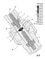
- FIG. 9 shows the FEA thermal model analysis results, with a color gradient from red to blue, red representing the hottest area. Letter notations are applied to representative areas of the model and to the corresponding temperature scale for ease of review. Un-dissipated heat at the central area 50 would have built up and, for example, melted the insulating element of the capacitive break 45 or otherwise thermally destroyed the device according to the physical tests on common PTFE insulator coaxial devices, described herein above.
- Figure 9 demonstrates a steady state thermal profile, in which the central area 50 and or capacitive break 45 never exceeds the heat limits of the coaxial RF device 40 materials.
- an insulator 10 may be applied to any coaxial RF device 40 where improved heat dissipation, and thereby greater power capacity is desired.
- the present invention may be applied as the supporting insulator 1 in coaxial portions of antennas and in-line coaxial devices such as surge arrestors, filters, bias-tees, signal taps, DC breaks, connectors or the like. Because heat dissipation and thereby power handling is so dramatically improved, the overall size of the devices may be reduced, further reducing materials costs, overall device weight and installation space requirements.
Abstract
Description
- The invention generally relates to improvements in the power handling capabilities of inline RF devices for use with coaxial cables. More particularly, the invention relates to methods and apparatus for improving heat dissipation in these devices via thermally conductive insulator(s).
- There is an escalation in the amount of power, such as system overlays, that Coaxial RF devices such as RF connectors and surge devices are being required to handle which in turn increases the heat generated in such devices. In particular, a DC Block or Bias-Tee element applied to the inner conductor of an in-line coaxial device will generate significant heat levels that, if not dissipated, may damage or destroy the device.
- Thermally conductive polymers incorporate a, for example, ceramic filler material to create a polymer with a greatly increased thermal conductivity characteristic. Heat sinks, enclosures and overmoldings applying thermally conductive polymers have been cost effectively formed via injection molding to improve heat dissipation characteristics for electrical components and or electrical circuit modules.
- Therefore, it is an object of the invention to provide an apparatus that overcomes deficiencies in the prior art.
- The accompanying drawings, which are incorporated in and constitute a part of this specification, illustrate embodiments of the invention and, together with a general description of the invention given above, and the detailed description of the embodiments given below, serve to explain the principles of the invention.
- Figure 1 is an isometric view of an exemplary thermally conductive insulator according to the invention.
- Figure 2 is a section view of figure 3, along line A-A.
- Figure 3 is an side schematic view of figure 1.
- Figure 4 is an isometric view of an alternative embodiment of a thermally conductive insulator according to the invention.
- Figure 5 is a section view of figure 6, along line A-A.
- Figure 6 is a side view of figure 4.
- Figure 7 is an isometric view of another alternative embodiment of a thermally conductive insulator according to the invention.
- Figure 8 is an isometric end view of figure 7.
- Figure 9 is a thermal model of a coaxial RF device shown in an isometric cross section, colored in a gradient between red and blue representing the temperature from hot to cold.
- In-line coaxial devices utilize insulators to position elements of the inner conductor coaxially within the outer conductor, without electrically coupling the inner and outer conductors. In the prior art, the insulator material was selected primarily based upon the dielectric value, ease of fabrication and cost. Typically, the insulators are polytetrafluoroethylene (PTFE) or polyetherimide (PEI) both of which have advantageous dielectric properties but that are both relatively non-thermally conductive.
- The inventor has recognized that these insulators and any enclosed air space between the inner conductor and the surrounding outer conductor create an insulated thermal pocket around a section of inner conductor and any devices coupled to the inner conductor there between. In devices according to the invention, the thermal insulating effect of the prior relatively non-thermally conductive insulators may be significantly reduced by application of a thermally conductive polymer composition. The high thermal conductivity capacity of these polymer compositions operates to create a conductive heat transfer path through the insulator to conduct heat away from the inner conductor to the outer conductor that then operates as an effective heat sink to the surrounding ambient atmosphere. By improving heat dissipation of the device, startling power handling capability improvements have been realized.
- PTFE has a thermal conductivity of 1.7 W/mK; the thermal conductivity for PEI is approximately 0.9 W/mK. For descriptive purposes, a thermally conductive polymer composition has a thermal conductivity characteristic of at least 4 W/mK. A thermally conductive polymer composition may be formed from a base polymer and thermally conductive filler material. The base polymer may be polyphenylene sulfide (PPS), thermoplastic elastomer (TPE), polypropylene (PP), liquid crystal polymer (LCP) or the like, and boron nitride particles, carbon fibers or ceramic particles may be used as the thermally conductive filler materials. In one exemplary thermally conductive polymer composition, the thermally conductive polymer composition includes 30 to 60% of a base polymer, 25% to 50% of a first thermally conductive filler material, and 10 to 25% of a second thermally conductive filler material. An example of a commercially available thermally conductive polymer composition with suitable dielectric properties is CoolPoly® D5108 from Cool Polymers, Inc. of Warwick, RI, which has a significantly improved thermal conductivity property of 10 W/mK.
- One consideration of a thermally conductive polymer composition application as a coaxial insulator is equalization of the dielectric constant of the resulting insulator with that of the coaxial line it is designed for use with. For example CoolPoly® D5108 has a dielectric constant, measured at one megahertz, of 3.7 while standard PTFE typically has a dielectric constant around 2.
- To compensate for an increased dielectric constant characteristic of the thermally conductive polymer composition, the cross sectional area of the
insulator 1 may be adjusted. For example, as shown in figures 1-8 aninsulator 1 may be formed with a plurality of pockets orother cavities 5 applied to adjust the cross sectional area of a portion of thermally conductive polymer composition dimensioned to contact anouter conductor 15 of the coaxial line around anouter periphery 10 and having acentral bore 20 dimensioned to contact theinner conductor 25. As shown for example in figures 7 and 8, thecavities 5 may be formed in a circle sector shape, preferably having fourcavities 5, creating a uniformly distributed spoke configuration in the remaining material adaptable for two axis mold separation during fabrication, for example, via injection molding. Alternatively, theinsulator 10 may be formed in a cylindrical form with, for example, cavities at afront end 30 and or at aback end 35. To improve mold release characteristics during manufacture via injection molding, each of the pockets and or cavities may be formed open to only one face of theinsulator 10. - The inventor tested an Andrew Corporation ABT-DFDM-DB Coaxial Bias-Tee Device with conventional solid cylindrical PTFE non-thermally conductive insulators at each end. The device experienced thermal failure after several minutes of operation at 500 W @ 883 MHz plus a 250 W @ 1940 MHz overlay. When the insulators, only, were exchanged with thermally conductive polymer composition insulators, specifically the CoolPoly® D5108 thermally conductive material, the device operated in a steady state at 244° F under a further 160 W reflected load for a total of 910 W.
- Further, FEA thermal modeling analysis was performed based upon 5 watts steady thermal load applied to a
capacitive break 45 on the center conductor of acoaxial RF device 40, the center conductor supported byinsulators 10 of a thermally conductive polymer composition according to the invention. Figure 9 shows the FEA thermal model analysis results, with a color gradient from red to blue, red representing the hottest area. Letter notations are applied to representative areas of the model and to the corresponding temperature scale for ease of review. Un-dissipated heat at thecentral area 50 would have built up and, for example, melted the insulating element of thecapacitive break 45 or otherwise thermally destroyed the device according to the physical tests on common PTFE insulator coaxial devices, described herein above. In contrast, Figure 9 demonstrates a steady state thermal profile, in which thecentral area 50 and orcapacitive break 45 never exceeds the heat limits of thecoaxial RF device 40 materials. - One skilled in the art will appreciate that an
insulator 10 according to the present invention may be applied to anycoaxial RF device 40 where improved heat dissipation, and thereby greater power capacity is desired. For example, the present invention may be applied as the supportinginsulator 1 in coaxial portions of antennas and in-line coaxial devices such as surge arrestors, filters, bias-tees, signal taps, DC breaks, connectors or the like. Because heat dissipation and thereby power handling is so dramatically improved, the overall size of the devices may be reduced, further reducing materials costs, overall device weight and installation space requirements.Table of Parts 1 insulator 5 cavity 10 outer periphery 15 outer conductor 20 central bore 25 inner conductor 30 front end 35 back end 40 coaxial RF device 45 capacitive break 50 central area - Where in the foregoing description reference has been made to ratios, integers, components or modules having known equivalents then such equivalents are herein incorporated as if individually set forth.
- While the present invention has been illustrated by the description of the embodiments thereof, and while the embodiments have been described in considerable detail, it is not the intention of the applicant to restrict or in any way limit the scope of the appended claims to such detail. Additional advantages and modifications will readily appear to those skilled in the art. Therefore, the invention in its broader aspects is not limited to the specific details, representative apparatus, methods, and illustrative examples shown and described. Accordingly, departures may be made from such details without departure from the spirit or scope of applicant's general inventive concept. Further, it is to be appreciated that improvements and/or modifications may be made thereto without departing from the scope or spirit of the present invention as defined by the following claims.
Claims (20)
- An insulator supporting an inner conductor within the outer conductor of a coaxial device, comprising:a portion of thermally conductive polymer composition with a thermal conductivity of at least 4 W/m-K; the portion dimensioned with an outer diameter in contact with the outer conductor and a coaxial central bore supporting there through the inner conductor.
- The insulator of claim 1, further including a plurality of cavities formed in the outer diameter.
- The insulator of claim 2, wherein the plurality of cavities are each equal in size.
- The insulator of claim 2, wherein the plurality of cavities is four.
- The insulator of claim 2, wherein the plurality of cavities each are a generally circle sector shape.
- The insulator of claim 1, further including a plurality of cavities provided in a front side and a back side of the insulator.
- The insulator of claim 1, further including at least one cavity provided in one of a front side and a back side of the insulator.
- The insulator of claim 1, wherein the thermally conductive polymer composition has a dielectric constant, measured at one megahertz, of less than 4.
- The insulator of claim 1, wherein the thermal conductivity is at least 10 W/m-K.
- The insulator of claim 1, wherein the insulator is cylindrical.
- The insulator of claim 1, wherein the portion is a unitary integral portion.
- A method for manufacturing an insulator for supporting an inner conductor within an outer conductor of a coaxial device, comprising the steps of:forming a portion of thermally conductive polymer composition with a thermal conductivity of at least 4 W/m-K; the portion dimensioned to have an outer diameter in contact with the outer conductor and a coaxial central bore in contact with the inner conductor.
- The method of claim 12, wherein the portion is formed via injection molding.
- The method of claim 12, wherein the portion is cylindrical.
- The method of claim 12, further including forming a plurality of cavities in the portion.
- The method of claim 12, wherein the cavities are arranged for two axis mold separation during forming via injection molding.
- The method of claim 15, wherein the cavities are uniformly distributed around the portion.
- The method of claim 12, wherein the thermally conductive polymer composition has a thermal conductivity of at least 10 W/m-K.
- The method of claim 12, wherein the dielectric value of the thermally conductive polymer composition, measured at one megahertz, is less than 4.
- The method of claim 12, wherein the portion is formed as a unitary integral portion.
Applications Claiming Priority (2)
| Application Number | Priority Date | Filing Date | Title |
|---|---|---|---|
| US74793406P | 2006-05-22 | 2006-05-22 | |
| US11/690,091 US7705238B2 (en) | 2006-05-22 | 2007-03-22 | Coaxial RF device thermally conductive polymer insulator and method of manufacture |
Publications (3)
| Publication Number | Publication Date |
|---|---|
| EP1870955A2 true EP1870955A2 (en) | 2007-12-26 |
| EP1870955A3 EP1870955A3 (en) | 2008-07-23 |
| EP1870955B1 EP1870955B1 (en) | 2011-11-30 |
Family
ID=38608940
Family Applications (1)
| Application Number | Title | Priority Date | Filing Date |
|---|---|---|---|
| EP07106811A Not-in-force EP1870955B1 (en) | 2006-05-22 | 2007-04-24 | Coaxial RF device thermally conductive polymer insulator and method of manufacture |
Country Status (7)
| Country | Link |
|---|---|
| US (1) | US7705238B2 (en) |
| EP (1) | EP1870955B1 (en) |
| JP (1) | JP5176062B2 (en) |
| AT (1) | ATE535960T1 (en) |
| BR (1) | BRPI0702308A (en) |
| CA (1) | CA2585097A1 (en) |
| MX (1) | MX2007004984A (en) |
Families Citing this family (19)
| Publication number | Priority date | Publication date | Assignee | Title |
|---|---|---|---|---|
| DE102008012591B4 (en) * | 2008-02-15 | 2013-08-29 | Rohde & Schwarz Gmbh & Co. Kg | Coaxial cable with support disks |
| US8022296B2 (en) * | 2009-01-21 | 2011-09-20 | John Mezzalingua Associates, Inc. | Coaxial cable connector insulator and method of use thereof |
| KR101796098B1 (en) * | 2010-01-22 | 2017-11-10 | 누보트로닉스, 인크. | Thermal management |
| US8622762B2 (en) * | 2010-11-22 | 2014-01-07 | Andrew Llc | Blind mate capacitively coupled connector |
| US9768574B2 (en) | 2010-11-22 | 2017-09-19 | Commscope Technologies Llc | Cylindrical surface spin weld apparatus |
| US9761959B2 (en) | 2010-11-22 | 2017-09-12 | Commscope Technologies Llc | Ultrasonic weld coaxial connector |
| US8826525B2 (en) | 2010-11-22 | 2014-09-09 | Andrew Llc | Laser weld coaxial connector and interconnection method |
| US8365404B2 (en) | 2010-11-22 | 2013-02-05 | Andrew Llc | Method for ultrasonic welding a coaxial cable to a coaxial connector |
| US9728926B2 (en) | 2010-11-22 | 2017-08-08 | Commscope Technologies Llc | Method and apparatus for radial ultrasonic welding interconnected coaxial connector |
| US8887388B2 (en) | 2010-11-22 | 2014-11-18 | Andrew Llc | Method for interconnecting a coaxial connector with a solid outer conductor coaxial cable |
| US8814601B1 (en) | 2011-06-06 | 2014-08-26 | Nuvotronics, Llc | Batch fabricated microconnectors |
| WO2013138266A1 (en) * | 2012-03-12 | 2013-09-19 | Molex Incorporated | Power connector with thermal conductivity |
| NO20120777A1 (en) * | 2012-07-04 | 2014-01-06 | Aker Subsea As | Heat dissipation in power cables, power umbilicals and other cables |
| US8801460B2 (en) * | 2012-11-09 | 2014-08-12 | Andrew Llc | RF shielded capacitively coupled connector |
| US9425548B2 (en) * | 2012-11-09 | 2016-08-23 | Commscope Technologies Llc | Resilient coaxial connector interface and method of manufacture |
| US8926360B2 (en) * | 2013-01-17 | 2015-01-06 | Cooper Technologies Company | Active cooling of electrical connectors |
| FR3006119B1 (en) * | 2013-05-22 | 2015-05-29 | Legrand France | ELECTRICAL EQUIPMENT COMPRISING A TEMPERATURE SENSOR LOCATED IN A SUPPORT MEMBER |
| TWI671851B (en) * | 2016-09-22 | 2019-09-11 | 美商應用材料股份有限公司 | Heater pedestal assembly for wide range temperature control |
| FR3116646B1 (en) * | 2020-11-26 | 2023-06-30 | Thales Sa | Power cable with integrated filter |
Citations (8)
| Publication number | Priority date | Publication date | Assignee | Title |
|---|---|---|---|---|
| US3310520A (en) | 1961-05-24 | 1967-03-21 | Roland T Girard | Beryllium oxide-organic resin composition |
| DE1906286A1 (en) | 1969-02-08 | 1970-12-23 | Kabel Metallwerke Ghh | Air spaced coaxial high frequency cable |
| DE2121688A1 (en) | 1971-04-29 | 1972-11-09 | Siemens AG, 1000 Berlin u. 8000 München | Coaxial high frequency cable - with polyethylene core, insulation and outer casing |
| EP0729158A1 (en) | 1995-02-24 | 1996-08-28 | Sumitomo Wiring Systems, Ltd. | Radiation wire |
| WO1998001870A1 (en) | 1996-07-01 | 1998-01-15 | Nk Cables Oy | Coaxial high-frequency cable and dielectric material thereof |
| WO1999057190A1 (en) | 1998-05-04 | 1999-11-11 | R.T. Vanderbilt Company, Inc. | Stabilizer compositions for polymeric insulations |
| WO2001054141A1 (en) | 2000-01-18 | 2001-07-26 | Scilogy Corporation | High flexibility and heat dissipating coaxial cable |
| US6733324B1 (en) | 2002-12-06 | 2004-05-11 | Com Dev Ltd. | Coaxial heat sink connector |
Family Cites Families (27)
| Publication number | Priority date | Publication date | Assignee | Title |
|---|---|---|---|---|
| NL70908C (en) * | 1946-01-18 | |||
| DE1465637B2 (en) * | 1963-08-22 | 1971-09-30 | Kabel- und Metallwerke Gutehoffnungshütte AG, 3000 Hannover | SPACER FOR COAXIAL HIGH FREQUENCY CABLES |
| NL160422C (en) * | 1974-05-21 | 1979-10-15 | Philips Nv | PROCESS FOR MANUFACTURE OF A COAXIAL CABLE AND COAXIAL CABLE OBTAINED BY THIS PROCESS. |
| US4240124A (en) * | 1979-06-01 | 1980-12-16 | Kearney-National Inc. | Surge arrester having coaxial shunt gap |
| US5309320A (en) * | 1991-02-06 | 1994-05-03 | Hughes Aircraft Company | Circuit card assembly conduction converter |
| DE69426501T2 (en) * | 1993-10-07 | 2001-05-03 | Andrew Corp | Overvoltage protection connector |
| FR2747832B1 (en) * | 1996-04-23 | 1998-05-22 | Filotex Sa | METHOD AND DEVICE FOR MANUFACTURING A VENTILATED SHEATH IN AN INSULATING MATERIAL AROUND A CONDUCTOR, AND COAXIAL CABLE EQUIPPED WITH SUCH SHEATH |
| US5812374A (en) * | 1996-10-28 | 1998-09-22 | Shuff; Gregg Douglas | Electrical circuit cooling device |
| DE19737759A1 (en) * | 1997-08-29 | 1999-03-04 | Alsthom Cge Alcatel | Coaxial radio frequency cable |
| US6367541B2 (en) * | 1999-05-06 | 2002-04-09 | Cool Options, Inc. | Conforming heat sink assembly |
| US6487073B2 (en) * | 1999-12-01 | 2002-11-26 | Cool Options, Inc. | Thermally conductive electronic device case |
| US6201700B1 (en) * | 2000-01-06 | 2001-03-13 | Ford Motor Company | Box design for maximum heat dissipation |
| US6377219B2 (en) * | 2000-01-11 | 2002-04-23 | Cool Options, Inc. | Composite molded antenna assembly |
| US6817096B2 (en) * | 2000-01-11 | 2004-11-16 | Cool Options, Inc. | Method of manufacturing a heat pipe construction |
| US6851869B2 (en) * | 2000-08-04 | 2005-02-08 | Cool Options, Inc. | Highly thermally conductive electronic connector |
| US6543524B2 (en) * | 2000-11-29 | 2003-04-08 | Cool Options, Inc. | Overplated thermally conductive part with EMI shielding |
| US6420963B1 (en) * | 2001-02-16 | 2002-07-16 | Scientific-Atlanta, Inc. | Plastic housing including a conductive liner for use with an electronic device |
| US6870246B1 (en) * | 2001-08-31 | 2005-03-22 | Rambus Inc. | Method and apparatus for providing an integrated circuit cover |
| US7124806B1 (en) * | 2001-12-10 | 2006-10-24 | Ncr Corp. | Heat sink for enhanced heat dissipation |
| US6815617B1 (en) * | 2002-01-15 | 2004-11-09 | Belden Technologies, Inc. | Serrated cable core |
| US20030170883A1 (en) * | 2002-03-11 | 2003-09-11 | Corning Incorporated | Microplate manufactured from a thermally conductive material and methods for making and using such microplates |
| TW200405363A (en) * | 2002-08-06 | 2004-04-01 | Ube Nitto Kasei Co | Thin-diameter coaxial cable and method of producing the same |
| US6919504B2 (en) * | 2002-12-19 | 2005-07-19 | 3M Innovative Properties Company | Flexible heat sink |
| US6976769B2 (en) * | 2003-06-11 | 2005-12-20 | Cool Options, Inc. | Light-emitting diode reflector assembly having a heat pipe |
| US7462451B2 (en) * | 2004-04-26 | 2008-12-09 | Third Wave Technologies, Inc. | Compositions for modifying nucleic acids |
| US7147041B2 (en) * | 2004-05-03 | 2006-12-12 | Parker-Hannifin Corporation | Lightweight heat sink |
| JP4904732B2 (en) * | 2004-07-08 | 2012-03-28 | 東レ株式会社 | Thermally conductive molded body and method for producing the same |
-
2007
- 2007-03-22 US US11/690,091 patent/US7705238B2/en active Active
- 2007-04-17 CA CA002585097A patent/CA2585097A1/en not_active Abandoned
- 2007-04-24 AT AT07106811T patent/ATE535960T1/en active
- 2007-04-24 EP EP07106811A patent/EP1870955B1/en not_active Not-in-force
- 2007-04-25 MX MX2007004984A patent/MX2007004984A/en active IP Right Grant
- 2007-05-17 JP JP2007131920A patent/JP5176062B2/en not_active Expired - Fee Related
- 2007-05-21 BR BRPI0702308-1A patent/BRPI0702308A/en not_active IP Right Cessation
Patent Citations (8)
| Publication number | Priority date | Publication date | Assignee | Title |
|---|---|---|---|---|
| US3310520A (en) | 1961-05-24 | 1967-03-21 | Roland T Girard | Beryllium oxide-organic resin composition |
| DE1906286A1 (en) | 1969-02-08 | 1970-12-23 | Kabel Metallwerke Ghh | Air spaced coaxial high frequency cable |
| DE2121688A1 (en) | 1971-04-29 | 1972-11-09 | Siemens AG, 1000 Berlin u. 8000 München | Coaxial high frequency cable - with polyethylene core, insulation and outer casing |
| EP0729158A1 (en) | 1995-02-24 | 1996-08-28 | Sumitomo Wiring Systems, Ltd. | Radiation wire |
| WO1998001870A1 (en) | 1996-07-01 | 1998-01-15 | Nk Cables Oy | Coaxial high-frequency cable and dielectric material thereof |
| WO1999057190A1 (en) | 1998-05-04 | 1999-11-11 | R.T. Vanderbilt Company, Inc. | Stabilizer compositions for polymeric insulations |
| WO2001054141A1 (en) | 2000-01-18 | 2001-07-26 | Scilogy Corporation | High flexibility and heat dissipating coaxial cable |
| US6733324B1 (en) | 2002-12-06 | 2004-05-11 | Com Dev Ltd. | Coaxial heat sink connector |
Also Published As
| Publication number | Publication date |
|---|---|
| ATE535960T1 (en) | 2011-12-15 |
| EP1870955A3 (en) | 2008-07-23 |
| JP2007317660A (en) | 2007-12-06 |
| BRPI0702308A (en) | 2008-01-15 |
| US7705238B2 (en) | 2010-04-27 |
| CA2585097A1 (en) | 2007-11-22 |
| US20070267717A1 (en) | 2007-11-22 |
| JP5176062B2 (en) | 2013-04-03 |
| EP1870955B1 (en) | 2011-11-30 |
| MX2007004984A (en) | 2008-10-29 |
Similar Documents
| Publication | Publication Date | Title |
|---|---|---|
| US7705238B2 (en) | Coaxial RF device thermally conductive polymer insulator and method of manufacture | |
| US7450363B2 (en) | Combination electrical connector | |
| US6972941B2 (en) | Fixing and protecting arrangement for a capacitor | |
| CN106810876B (en) | Composite material with directionally arranged fillers and preparation method thereof | |
| CN101901983A (en) | Very-high-power connector | |
| US6733324B1 (en) | Coaxial heat sink connector | |
| US20100207600A1 (en) | Variable-Electric-Power Self-Regulating Cable Exhibiting PTC Behaviour, Connector Therefor, a Device Comprising Them, and Use of Said Device | |
| CN101079340A (en) | Coaxial RF device thermally conductive polymer insulator and method of manufacture | |
| CA2253325A1 (en) | Microwave testing high-power dummy load forming method and microwave testing high-power dummy load apparatus | |
| CN207381385U (en) | A kind of semiconductor device of the operation is stable | |
| CN104303368B (en) | For the pole connector of series trip device | |
| JP5431220B2 (en) | Solid insulation switchgear heat dissipation device | |
| CA2940072C (en) | Power cable termination device for gas-insulated switchgear | |
| US8816792B2 (en) | High power, low-passive intermodulation microwave termination | |
| Panahi et al. | An efficient high power RF dummy-load | |
| JP7355362B2 (en) | Magnetic core, method for manufacturing the magnetic core, and balun equipped with the magnetic core | |
| Miswan et al. | Thermal performance of ferrule designs for medium voltage cable jointing | |
| US9444230B2 (en) | Power distribution assembly and header assembly therefor | |
| WO2007063592A1 (en) | Signal coupling device and method for fabricating the same | |
| US20060121761A1 (en) | High-amperage electrical bushing connector |
Legal Events
| Date | Code | Title | Description |
|---|---|---|---|
| PUAI | Public reference made under article 153(3) epc to a published international application that has entered the european phase |
Free format text: ORIGINAL CODE: 0009012 |
|
| AK | Designated contracting states |
Kind code of ref document: A2 Designated state(s): AT BE BG CH CY CZ DE DK EE ES FI FR GB GR HU IE IS IT LI LT LU LV MC MT NL PL PT RO SE SI SK TR |
|
| AX | Request for extension of the european patent |
Extension state: AL BA HR MK YU |
|
| PUAL | Search report despatched |
Free format text: ORIGINAL CODE: 0009013 |
|
| AK | Designated contracting states |
Kind code of ref document: A3 Designated state(s): AT BE BG CH CY CZ DE DK EE ES FI FR GB GR HU IE IS IT LI LT LU LV MC MT NL PL PT RO SE SI SK TR |
|
| AX | Request for extension of the european patent |
Extension state: AL BA HR MK RS |
|
| 17P | Request for examination filed |
Effective date: 20090112 |
|
| 17Q | First examination report despatched |
Effective date: 20090219 |
|
| AKX | Designation fees paid |
Designated state(s): AT BE BG CH CY CZ DE DK EE ES FI FR GB GR HU IE IS IT LI LT LU LV MC MT NL PL PT RO SE SI SK TR |
|
| GRAP | Despatch of communication of intention to grant a patent |
Free format text: ORIGINAL CODE: EPIDOSNIGR1 |
|
| GRAS | Grant fee paid |
Free format text: ORIGINAL CODE: EPIDOSNIGR3 |
|
| GRAA | (expected) grant |
Free format text: ORIGINAL CODE: 0009210 |
|
| AK | Designated contracting states |
Kind code of ref document: B1 Designated state(s): AT BE BG CH CY CZ DE DK EE ES FI FR GB GR HU IE IS IT LI LT LU LV MC MT NL PL PT RO SE SI SK TR |
|
| REG | Reference to a national code |
Ref country code: CH Ref legal event code: EP Ref country code: GB Ref legal event code: FG4D |
|
| REG | Reference to a national code |
Ref country code: IE Ref legal event code: FG4D |
|
| REG | Reference to a national code |
Ref country code: DE Ref legal event code: R096 Ref document number: 602007019019 Country of ref document: DE Effective date: 20120301 |
|
| REG | Reference to a national code |
Ref country code: NL Ref legal event code: VDEP Effective date: 20111130 |
|
| REG | Reference to a national code |
Ref country code: CH Ref legal event code: NV Representative=s name: OFFICE ERNEST T. FREYLINGER S.A. Ref country code: CH Ref legal event code: PFA Owner name: ANDREW CORPORATION Free format text: ANDREW CORPORATION#3 WESTBROOK CORPORATE CENTER, SUITE 900#WESTCHESTER, IL 60154 (US) -TRANSFER TO- ANDREW CORPORATION#1100 COMMSCOPE PLACE SE#HICKORY, NC 28602 (US) |
|
| LTIE | Lt: invalidation of european patent or patent extension |
Effective date: 20111130 |
|
| PG25 | Lapsed in a contracting state [announced via postgrant information from national office to epo] |
Ref country code: LT Free format text: LAPSE BECAUSE OF FAILURE TO SUBMIT A TRANSLATION OF THE DESCRIPTION OR TO PAY THE FEE WITHIN THE PRESCRIBED TIME-LIMIT Effective date: 20111130 Ref country code: IS Free format text: LAPSE BECAUSE OF FAILURE TO SUBMIT A TRANSLATION OF THE DESCRIPTION OR TO PAY THE FEE WITHIN THE PRESCRIBED TIME-LIMIT Effective date: 20120330 |
|
| PG25 | Lapsed in a contracting state [announced via postgrant information from national office to epo] |
Ref country code: BE Free format text: LAPSE BECAUSE OF FAILURE TO SUBMIT A TRANSLATION OF THE DESCRIPTION OR TO PAY THE FEE WITHIN THE PRESCRIBED TIME-LIMIT Effective date: 20111130 Ref country code: GR Free format text: LAPSE BECAUSE OF FAILURE TO SUBMIT A TRANSLATION OF THE DESCRIPTION OR TO PAY THE FEE WITHIN THE PRESCRIBED TIME-LIMIT Effective date: 20120301 Ref country code: SI Free format text: LAPSE BECAUSE OF FAILURE TO SUBMIT A TRANSLATION OF THE DESCRIPTION OR TO PAY THE FEE WITHIN THE PRESCRIBED TIME-LIMIT Effective date: 20111130 Ref country code: NL Free format text: LAPSE BECAUSE OF FAILURE TO SUBMIT A TRANSLATION OF THE DESCRIPTION OR TO PAY THE FEE WITHIN THE PRESCRIBED TIME-LIMIT Effective date: 20111130 Ref country code: SE Free format text: LAPSE BECAUSE OF FAILURE TO SUBMIT A TRANSLATION OF THE DESCRIPTION OR TO PAY THE FEE WITHIN THE PRESCRIBED TIME-LIMIT Effective date: 20111130 Ref country code: PT Free format text: LAPSE BECAUSE OF FAILURE TO SUBMIT A TRANSLATION OF THE DESCRIPTION OR TO PAY THE FEE WITHIN THE PRESCRIBED TIME-LIMIT Effective date: 20120330 Ref country code: LV Free format text: LAPSE BECAUSE OF FAILURE TO SUBMIT A TRANSLATION OF THE DESCRIPTION OR TO PAY THE FEE WITHIN THE PRESCRIBED TIME-LIMIT Effective date: 20111130 |
|
| PG25 | Lapsed in a contracting state [announced via postgrant information from national office to epo] |
Ref country code: CY Free format text: LAPSE BECAUSE OF FAILURE TO SUBMIT A TRANSLATION OF THE DESCRIPTION OR TO PAY THE FEE WITHIN THE PRESCRIBED TIME-LIMIT Effective date: 20111130 |
|
| PG25 | Lapsed in a contracting state [announced via postgrant information from national office to epo] |
Ref country code: DK Free format text: LAPSE BECAUSE OF FAILURE TO SUBMIT A TRANSLATION OF THE DESCRIPTION OR TO PAY THE FEE WITHIN THE PRESCRIBED TIME-LIMIT Effective date: 20111130 Ref country code: SK Free format text: LAPSE BECAUSE OF FAILURE TO SUBMIT A TRANSLATION OF THE DESCRIPTION OR TO PAY THE FEE WITHIN THE PRESCRIBED TIME-LIMIT Effective date: 20111130 Ref country code: EE Free format text: LAPSE BECAUSE OF FAILURE TO SUBMIT A TRANSLATION OF THE DESCRIPTION OR TO PAY THE FEE WITHIN THE PRESCRIBED TIME-LIMIT Effective date: 20111130 Ref country code: BG Free format text: LAPSE BECAUSE OF FAILURE TO SUBMIT A TRANSLATION OF THE DESCRIPTION OR TO PAY THE FEE WITHIN THE PRESCRIBED TIME-LIMIT Effective date: 20120229 Ref country code: CZ Free format text: LAPSE BECAUSE OF FAILURE TO SUBMIT A TRANSLATION OF THE DESCRIPTION OR TO PAY THE FEE WITHIN THE PRESCRIBED TIME-LIMIT Effective date: 20111130 |
|
| PGFP | Annual fee paid to national office [announced via postgrant information from national office to epo] |
Ref country code: CH Payment date: 20120425 Year of fee payment: 6 |
|
| PG25 | Lapsed in a contracting state [announced via postgrant information from national office to epo] |
Ref country code: IT Free format text: LAPSE BECAUSE OF FAILURE TO SUBMIT A TRANSLATION OF THE DESCRIPTION OR TO PAY THE FEE WITHIN THE PRESCRIBED TIME-LIMIT Effective date: 20111130 Ref country code: RO Free format text: LAPSE BECAUSE OF FAILURE TO SUBMIT A TRANSLATION OF THE DESCRIPTION OR TO PAY THE FEE WITHIN THE PRESCRIBED TIME-LIMIT Effective date: 20111130 Ref country code: PL Free format text: LAPSE BECAUSE OF FAILURE TO SUBMIT A TRANSLATION OF THE DESCRIPTION OR TO PAY THE FEE WITHIN THE PRESCRIBED TIME-LIMIT Effective date: 20111130 |
|
| PGFP | Annual fee paid to national office [announced via postgrant information from national office to epo] |
Ref country code: FI Payment date: 20120427 Year of fee payment: 6 |
|
| REG | Reference to a national code |
Ref country code: AT Ref legal event code: MK05 Ref document number: 535960 Country of ref document: AT Kind code of ref document: T Effective date: 20111130 |
|
| PLBE | No opposition filed within time limit |
Free format text: ORIGINAL CODE: 0009261 |
|
| STAA | Information on the status of an ep patent application or granted ep patent |
Free format text: STATUS: NO OPPOSITION FILED WITHIN TIME LIMIT |
|
| 26N | No opposition filed |
Effective date: 20120831 |
|
| PG25 | Lapsed in a contracting state [announced via postgrant information from national office to epo] |
Ref country code: MC Free format text: LAPSE BECAUSE OF NON-PAYMENT OF DUE FEES Effective date: 20120430 |
|
| REG | Reference to a national code |
Ref country code: DE Ref legal event code: R097 Ref document number: 602007019019 Country of ref document: DE Effective date: 20120831 |
|
| REG | Reference to a national code |
Ref country code: IE Ref legal event code: MM4A |
|
| PG25 | Lapsed in a contracting state [announced via postgrant information from national office to epo] |
Ref country code: IE Free format text: LAPSE BECAUSE OF NON-PAYMENT OF DUE FEES Effective date: 20120424 Ref country code: AT Free format text: LAPSE BECAUSE OF FAILURE TO SUBMIT A TRANSLATION OF THE DESCRIPTION OR TO PAY THE FEE WITHIN THE PRESCRIBED TIME-LIMIT Effective date: 20111130 |
|
| PG25 | Lapsed in a contracting state [announced via postgrant information from national office to epo] |
Ref country code: ES Free format text: LAPSE BECAUSE OF FAILURE TO SUBMIT A TRANSLATION OF THE DESCRIPTION OR TO PAY THE FEE WITHIN THE PRESCRIBED TIME-LIMIT Effective date: 20120311 |
|
| PG25 | Lapsed in a contracting state [announced via postgrant information from national office to epo] |
Ref country code: MT Free format text: LAPSE BECAUSE OF FAILURE TO SUBMIT A TRANSLATION OF THE DESCRIPTION OR TO PAY THE FEE WITHIN THE PRESCRIBED TIME-LIMIT Effective date: 20111130 |
|
| PGFP | Annual fee paid to national office [announced via postgrant information from national office to epo] |
Ref country code: DE Payment date: 20130429 Year of fee payment: 7 Ref country code: GB Payment date: 20130429 Year of fee payment: 7 |
|
| PGFP | Annual fee paid to national office [announced via postgrant information from national office to epo] |
Ref country code: FR Payment date: 20130506 Year of fee payment: 7 |
|
| REG | Reference to a national code |
Ref country code: CH Ref legal event code: PL |
|
| PG25 | Lapsed in a contracting state [announced via postgrant information from national office to epo] |
Ref country code: CH Free format text: LAPSE BECAUSE OF NON-PAYMENT OF DUE FEES Effective date: 20130430 Ref country code: LI Free format text: LAPSE BECAUSE OF NON-PAYMENT OF DUE FEES Effective date: 20130430 |
|
| PG25 | Lapsed in a contracting state [announced via postgrant information from national office to epo] |
Ref country code: FI Free format text: LAPSE BECAUSE OF NON-PAYMENT OF DUE FEES Effective date: 20130424 |
|
| PG25 | Lapsed in a contracting state [announced via postgrant information from national office to epo] |
Ref country code: TR Free format text: LAPSE BECAUSE OF FAILURE TO SUBMIT A TRANSLATION OF THE DESCRIPTION OR TO PAY THE FEE WITHIN THE PRESCRIBED TIME-LIMIT Effective date: 20111130 |
|
| PG25 | Lapsed in a contracting state [announced via postgrant information from national office to epo] |
Ref country code: LU Free format text: LAPSE BECAUSE OF NON-PAYMENT OF DUE FEES Effective date: 20120424 |
|
| PG25 | Lapsed in a contracting state [announced via postgrant information from national office to epo] |
Ref country code: HU Free format text: LAPSE BECAUSE OF FAILURE TO SUBMIT A TRANSLATION OF THE DESCRIPTION OR TO PAY THE FEE WITHIN THE PRESCRIBED TIME-LIMIT Effective date: 20070424 |
|
| REG | Reference to a national code |
Ref country code: DE Ref legal event code: R119 Ref document number: 602007019019 Country of ref document: DE |
|
| GBPC | Gb: european patent ceased through non-payment of renewal fee |
Effective date: 20140424 |
|
| REG | Reference to a national code |
Ref country code: FR Ref legal event code: ST Effective date: 20141231 |
|
| PG25 | Lapsed in a contracting state [announced via postgrant information from national office to epo] |
Ref country code: GB Free format text: LAPSE BECAUSE OF NON-PAYMENT OF DUE FEES Effective date: 20140424 Ref country code: DE Free format text: LAPSE BECAUSE OF NON-PAYMENT OF DUE FEES Effective date: 20141101 |
|
| REG | Reference to a national code |
Ref country code: DE Ref legal event code: R119 Ref document number: 602007019019 Country of ref document: DE Effective date: 20141101 |
|
| PG25 | Lapsed in a contracting state [announced via postgrant information from national office to epo] |
Ref country code: FR Free format text: LAPSE BECAUSE OF NON-PAYMENT OF DUE FEES Effective date: 20140430 |