EP1870866A1 - Smoke alarm device - Google Patents
Smoke alarm device Download PDFInfo
- Publication number
- EP1870866A1 EP1870866A1 EP06090117A EP06090117A EP1870866A1 EP 1870866 A1 EP1870866 A1 EP 1870866A1 EP 06090117 A EP06090117 A EP 06090117A EP 06090117 A EP06090117 A EP 06090117A EP 1870866 A1 EP1870866 A1 EP 1870866A1
- Authority
- EP
- European Patent Office
- Prior art keywords
- smoke
- light
- smoke alarm
- alarm device
- test
- Prior art date
- Legal status (The legal status is an assumption and is not a legal conclusion. Google has not performed a legal analysis and makes no representation as to the accuracy of the status listed.)
- Granted
Links
Images


Classifications
-
- G—PHYSICS
- G08—SIGNALLING
- G08B—SIGNALLING OR CALLING SYSTEMS; ORDER TELEGRAPHS; ALARM SYSTEMS
- G08B29/00—Checking or monitoring of signalling or alarm systems; Prevention or correction of operating errors, e.g. preventing unauthorised operation
- G08B29/12—Checking intermittently signalling or alarm systems
- G08B29/14—Checking intermittently signalling or alarm systems checking the detection circuits
- G08B29/145—Checking intermittently signalling or alarm systems checking the detection circuits of fire detection circuits
-
- G—PHYSICS
- G08—SIGNALLING
- G08B—SIGNALLING OR CALLING SYSTEMS; ORDER TELEGRAPHS; ALARM SYSTEMS
- G08B17/00—Fire alarms; Alarms responsive to explosion
- G08B17/10—Actuation by presence of smoke or gases, e.g. automatic alarm devices for analysing flowing fluid materials by the use of optical means
- G08B17/11—Actuation by presence of smoke or gases, e.g. automatic alarm devices for analysing flowing fluid materials by the use of optical means using an ionisation chamber for detecting smoke or gas
- G08B17/113—Constructional details
-
- G—PHYSICS
- G08—SIGNALLING
- G08B—SIGNALLING OR CALLING SYSTEMS; ORDER TELEGRAPHS; ALARM SYSTEMS
- G08B29/00—Checking or monitoring of signalling or alarm systems; Prevention or correction of operating errors, e.g. preventing unauthorised operation
- G08B29/02—Monitoring continuously signalling or alarm systems
- G08B29/04—Monitoring of the detection circuits
- G08B29/043—Monitoring of the detection circuits of fire detection circuits
-
- G—PHYSICS
- G08—SIGNALLING
- G08B—SIGNALLING OR CALLING SYSTEMS; ORDER TELEGRAPHS; ALARM SYSTEMS
- G08B29/00—Checking or monitoring of signalling or alarm systems; Prevention or correction of operating errors, e.g. preventing unauthorised operation
- G08B29/02—Monitoring continuously signalling or alarm systems
- G08B29/10—Monitoring of the annunciator circuits
Definitions
- the invention relates to a smoke alarm device comprising a housing with a smoke inlet and a smoke sensor device for detecting smoke entering the smoke alarm device through the smoke inlet in order to trigger an alarm signal.
- Smoke alarms of the designated type are usually designed as photoelectric smoke detectors.
- the smoke sensor device then works with stray light in an optical chamber.
- the smoke detectors are installed on ceilings or walls in hotels, larger residential buildings, department stores, public buildings, etc. They are also used in smaller living or room units.
- the smoke detectors usually warn with an acoustic signal when smoke is generated in the event of a fire.
- photoelectric smoke detectors such as the basic principle in US 2006/0017580 described, are well known.
- the functionality of the smoke alarm must be ensured to a special degree.
- standards eg German DIN standard 14676
- it is required to subject the smoke detector to a functional test at least once a year.
- An essential part of such a test is to check whether the smoke intrusion openings of the smoke detector are free. These can in particular by adhesive tape, paint or contamination z. B. be closed after renovations.
- the test is usually done by visual inspection. Instead, or in addition, a test method is to spray the smoke alarm with a smoke spray to test the proper warning function.
- a portable computer system US 6,469,623 .
- electronic circuits of smoke sensor devices are equipped with a self-test function.
- the aim is to ensure that the smoke penetrant ability is tested independently of the presence of smoke and without inspection by maintenance personnel.
- the smoke inlet has at least one passage area, which is associated with a passage-testing device, which detects the passage capability for smoke in the passage area, regardless of the presence of smoke.
- at least one smoke passage area is used to determine its opening state with technical means directly on the housing of the smoke alarm. This avoids the usual visual inspection and / or simulating smoke development.
- the test without subjective evaluation by maintenance personnel, at any time, without external interference, in particular by controlling with a test / test program and possibly with a protocol test data acquisition possible.
- the invention makes use in a particular embodiment of external light incident in the smoke inlet passage area to advantage.
- a smoke-input passage area to be inspected for passability which is accessible to outside light, is assigned an optical transmission tester which measures incident outside light according to the transmittance. It is particularly advantageous if the smoke inlet passage area with an impurities such as dust, insect od.
- Retaining filter is particularly equipped in the form of a grid and the light measurement on the filter and / or in the smoke inlet behind the smoke inlet facing away from the inside of the filter is set up.
- the filter achieves that, in particular, a labyrinth system which surrounds a scattered-light sensor device within the smoke detector and prevents the penetration of external / extraneous light there is not contaminated.
- a labyrinth system which surrounds a scattered-light sensor device within the smoke detector and prevents the penetration of external / extraneous light there is not contaminated.
- the optical transmission test device has at least one light-detecting measuring element.
- the light measuring element is formed by a ring element that extends in accordance with a circumferential extent of the smoke inlet with this.
- the ring member is advantageously formed transversely to the circumferential extent and corresponding to the width of the smoke inlet.
- Such an element may advantageously have a waveform.
- An embodiment of the ring element may be that it is designed as a light guide in the form of an open ring with at least one open ring end provided light exit surface, which is associated with a light receiving element of the optical test device.
- At least one light measuring element can also be formed by a lens, a prism and / or a light-conducting body in order to take into account special spatial conditions at the smoke passage area for detecting its light-opening area.
- At least a part of a wall of the smoke inlet form a light measuring element.
- a particularly simple design can also consist in that at least a part of an impurity-retaining filter forms a light-measuring element.
- At least one light-conducting measuring element determining the light path it will be expedient for at least one light-conducting measuring element determining the light path to be arranged in combination with at least one light-receiving element.
- at least one light measuring element without the interposition of a light-conducting measuring element can also be formed by a light-receiving element.
- a light receiving element is expediently formed in the form of a semiconductor element, a photodiode or the like.
- an embodiment may be that a plurality of light-receiving elements in a fan arrangement with aligned to the smoke inlet open fan side and a light receiver facing closed fan side are provided.
- At least one light measuring element is formed by a light receiving element that changes its electrical resistance when exposed to light.
- This version is particularly suitable for measuring elements that form parts of the detector housing, walls and / or grille or their components.
- the invention provides for optical test measurement of smoke intrusion, that the passage tester of the smoke alarm is in communication with a scholarlichtmelario arranged outside the smoke inlet passage area conveniently outside of the smoke alarm and for generating Test light is aligned with the smoke inlet passage area.
- the smoke detector is set up with an acoustic test device, which is connected and connected to an acoustic alarm transmitter of the smoke sensor device for testing the alarm function.
- the acoustic test device is set up with a microphone which receives an alarm signal triggered by the acoustic test device.
- the alarm emits a low-frequency, audible signal by means of the test device for a predetermined test time
- the acoustic test device can also be switched so that it generates a high-frequency inaudible signal on the acoustic alarm, the is received by a suitable microphone and is also representative of the functionality of the alarm in the listening area.
- a further embodiment consists in that the smoke alarm device has an installation test device which is connected to and connected to a position sensor for checking the mounting position.
- the housing of the smoke alarm on a working against the mounting surface spring means with an electrical switch, which is triggered when relaxing the spring due to disassembly of the smoke alarm to generate a test signal.
- the smoke detector can be conveniently set up with a self-diagnostic test device for functional testing of the smoke sensor device and possibly other circuits.
- the smoke detector also preferably has a supply test device for testing the electrical power supply.
- the smoke detector is set up with a programmable electronic signal processing and control circuit that controls and evaluates the test operation of equipped with at least one test device Rauchwammelders.
- the electronic signal processing and control circuit is connected and connected to at least one memory device which stores the operating and test results of the test operation.
- the smoke alarm device is expediently equipped with the smoke passage test device, an acoustic test device, an installation test device, a power supply test device and a self-diagnostic test device, which are operated in combination by means of the control circuit.
- the passage testing device can be electrically connected and connected to a visual and / or acoustic signal / alarm device arranged on the smoke alarm device in order to receive a message on site if the smoke passage is disturbed.
- a device for transmitting device, operating and / or test data to a location remote from the smoke detector Data collector device set up.
- the device is set up as a data communication device in the form of a radio transponder.
- the embodiment of the invention with a plurality of test devices and with the data transmission device in conjunction with a data collector device is of particular importance.
- the test can be carried out and recorded completely automatically without entering the room in which the smoke alarm device is installed. You get a readiness for use test that goes beyond the level of testing and allows you to diagnose and repair malfunctions in the short term after they occur and to perform maintenance on a detector with targeted planning and without much delay.
- requirements for a prescribed function control for example at the annual intervals, are more than fulfilled.
- the housing 11 has uniformly distributed over the circumference opening slots 21, which are divided by webs 12 in the circumferential slots, each extending over one-eighth of the circumference.
- a plurality of such slots 21, for example three are arranged over the flat housing height of the smoke alarm device 1.
- a conventional smoke sensor device 5 is arranged inside the smoke alarm device 1. Housing interior parts of the smoke alarm device 1 form a labyrinth 41 surrounding the smoke sensor device 5. This ensures that extraneous light L incident from the outside can not enter an optical darkroom 4 and no light is reflected by housing walls, while smoke R penetrates into the chamber 4.
- the smoke sensor device 5 has an infrared light-emitting diode (transmitting diode) 51 and a photodiode (receiver diode) 52 and a reflection wall 53. With these elements, the smoke sensor device 5 operates in the scattered light method. Pure air does not reflect light. But are smoke particles 54 in the optical chamber 4, then a portion of the light emitted from the diode 51 light is scattered, so that a portion of the light can reach the diode 52, whereby by means of an electronic circuit 50 of the smoke sensor device 5 an alarm / sounder 61 (Fig. 5) is triggered.
- a test device 3 is formed, which is independent of the presence of smoke, the permeability detects smoke in the passage area of the housing openings 21 and the impurity / dust filter 22.
- the passage testing device 3 comprises a first measuring element 31 and a second measuring element 32.
- the first measuring element 31 is formed by a circular open ring element. This is shown in Fig. 2 in side view. It is dimensioned so that it is located in the region between the filter 22 and the outer wall 42 of the labyrinth directly at a small distance next to the inside of the filter 22.
- ring members are formed of simple bodies in the form of an open loop for light.
- This ring line may suitably made of plastic fiber, z. B. be made of polyamide fibers.
- a portion of a line, string, or strand of such a plastic may be placed in the proper ring shape.
- the plastic material is transparent and light-conducting. It is important that the ring element 31 receives at its periphery an angle incident light L by refraction of light and forwards in the ring to light exit surfaces 310 at its open ends. These light exit surfaces 310 are located at vertically bent open ring ends, and they face the arranged in a dark room light measuring element 32.
- This is formed by an electro-optical light receiver.
- a photosensitive semiconductor element, a photodiode or a corresponding light-responsive electro-optical device may be provided.
- the light receiving element 32 is connected to an electronic signal processing and control circuit 8, as shown schematically in Fig. 5.
- the ring elements 31 are suitable for installation in the housing of conventional smoke detectors.
- the optical fiber strand for example, has a diameter of about 2 mm, reliably detects the light region of slot openings 21, the transverse to the circumferential extent of the element 31 substantially, z. B. about six times larger than the diameter of the element 31 may be. It can be seen that no significant disturbance or obstruction of the smoke inlet path takes place through the element 31. 2, a simply shaped ring is formed. Should the width of the smoke inlet 2 in the height of the smoke detector 1 be relatively large or should it be necessary to detect and detect even very small light intensities and / or light from different directions, then, as shown in FIGS.
- the light guide ring in the width dimension of the smoke inlet 2 formations, for example, in waveform received to increase the light absorption.
- a fiber strand of polyamide or other suitable photoconductive plastic which can be plastically deformed in particular for shaping. Any other material capable of trapping light along a body formed of the material and conducting it to at least one exit surface is contemplated for the conduction of light. As far as these requirements are met, for example, measuring element body made of fiberglass material are conceivable.
- the shape and characteristics of light-receiving and conductive measuring elements of the test device 3 are determined according to the type and design of a smoke detector.
- other light-receiving, collecting and / or conductive elements such as rod-shaped elements, lenses and prisms into consideration.
- the received or collected light is directed to one or more light receiving elements 32 in a dark room in the detector housing 11 of the smoke alarm device 1.
- light receiving elements may also be provided in a fan arrangement with an open fan side aligned with the smoke inlet and with a closed fan side facing the light receiver.
- a fan arrangement with an open fan side aligned with the smoke inlet and with a closed fan side facing the light receiver.
- different adapted arrangements are conceivable.
- other parts of the housing may be formed as light-conducting elements in the region of the smoke inlet 2.
- the ring measuring elements 31 shown in FIGS. 2 and 3 can also be designed as elements that change their electrical resistance when exposed to light.
- the rings then work directly as Lichtability- and receiving elements, so that they can be used without additional receiving elements and their resulting resistance change signals directly an electronic signal processing and control circuit 8 can be supplied.
- at least parts of the housing walls of the smoke inlet openings and / or parts of an impurity dust filter 22 may be formed of light-responsive resistance elements to perform the light measurement representing the inlet and passage of smoke in the smoke alarm device.
- Fig. 5 shows in a block diagram an embodiment of a smoke alarm device 1 according to the invention, which is equipped with the passage tester 3 and other test equipment, namely an acoustic test device 6, an installation tester 71, a power supply and test device 72 and a self-test diagnosis Testing device 73.
- the smoke alarm device 1 is also equipped with an electronic signal processing and control circuit 8, which evaluates measured signals, a memory device 81 and a radio data transmission device 82.
- FIG. 4 shows electronic building modules for the electronic devices 3 and 82.
- the device 82 is provided with a transmitting / receiving antenna 83. Non-visible modules for the other devices are also housed in the housing 11.
- the power supply 72 includes a battery.
- a test / test operation is started by a program of the signal processing and control circuit 8.
- Such electronics are provided in the form of a central control logic with CPU. Any other suitable circuit, program and control logic may be used.
- the test program tests the passage tester 3. The intensity of the light detected by the measuring elements 31 and 32 is measured and compared with a stored calibrated value. The comparison result is fed to the circuit 8 and stored in the memory device 81.
- the program also performs a test of the acoustic test device 6.
- a test generator 63 generates a low or high frequency signal which is applied to an alarm / sounder 61 and received by a microphone 62. The signal received thereby is applied via the device 6 to the circuit 8, which supplies the memory device 81 with a corresponding value representing the function status.
- the installation tester 71 is provided to check the correct mounting position of the smoke alarm device 1.
- the correct attachment to a building ceiling or wall is detected by means of a switching contact of the smoke detector 1, not shown.
- a spring-loaded be set electrical switch whose contact is interrupted when the spring load is eliminated by removing the detector 1 from the wall or ceiling.
- the state of the switch is, processed in the course of the controlling test program, by the circuit 8 and the memory device 81 is supplied.
- the smoke alarm device comprises the self-test diagnostic test device 73, which tests the function of the smoke sensor device 5 in the exemplary embodiment.
- self-diagnostic facilities may be provided for the functions of the aforementioned test facilities.
- the detector 1 is still equipped with the power supply and test device 73 for checking the power supply to all devices.
- the electronic signal processing and control circuit 8 evaluates the individual measurement results and signals and supplies the evaluation results to the memory device 81.
- the circuit 8 takes into account the program operation and the evaluation time and calendar data.
- the transmission device 82 (radio module) is expediently set up in the form of a known transponder.
- transponders are known, for example, for consumption data acquisition. Suitable transponders are used for example in DE 10 2004 055 659 described.
- the transponder is equipped for data communication with a receiver, not shown.
- the device 82 or the transponder cooperate with a data collector 9 shown in FIG.
- Data collector 9 and transponder 82 correspond to each other via radio signals from each transmitter and receiver.
- the data collector 9 is assigned a plurality of smoke detectors 1 of a residential or building unit.
- the stored data is transmitted to the receiving data collector 9 immediately or at a predetermined time.
- the reproduced in Fig. 6 protocol to a smoke detector 1 is created.
- this also records characteristic smoke detector data such as location information, device number and installation date.
- control program of the circuit 8 is set up so that the test is distributed over a day several times, for example three times, to ensure that at least in a time window for a clearly detectable and differentiable measurement enough light is available. If only one of the evaluated results is outside a prescribed tolerance taken into account with the circuit 8, this becomes visible in the protocol.
- the test process is terminated by the test and test program and triggered again at the next programmed date.
- the test / test program in the smoke detector 1 can also be triggered by the data collector 9.
- the data collector 9 comes to a test function. Thus, during installation, it is supplied with characteristic data by individual assigned smoke alarm devices. The test / test programs of a series of smoke detectors 1 in a residential / building unit are timed to each other. If a new protocol is created as part of this process, then the data collector 9 checks in the sequence whether the data is transferred from the group of reserved devices. If the data transmission of a smoke alarm device of the group is missing, this is recorded as a total failure of the relevant smoke alarm device in the protocol. A protocol that has been created in this way with the devices according to the invention is read out at least once a year.
- a service technician is instructed to inspect the identified smoke alarm device, remedy the fault and, if necessary, to replace the device. It can be seen that in particular site inspections which have traditionally been necessary for the examination of the ability to smoke are dispensed with by the measures according to the invention.
Abstract
Description
Die Erfindung betrifft einen Rauchwarnmelder, umfassend ein Gehäuse mit einem Raucheinlass und eine Rauch-Sensoreinrichtung zum Feststellen von durch den Raucheinlass in den Rauchwarnmelder eindringendem Rauch, um ein Alarmsignal auszulösen. Rauchwarnmelder der bezeichneten Art sind meist als fotoelektrische Rauchwarnmelder ausgeführt. Die Rauch-Sensoreinrichtung arbeitet dann mit Streulicht in einer optischen Kammer. Die Rauchwarnmelder werden an Decken oder Wänden in Hotels, größeren Wohngebäuden, Kaufhäusern, öffentlichen Gebäuden etc. angebracht. Sie werden auch in kleineren Wohn- oder Raumeinheiten eingesetzt. Die Rauchwarnmelder warnen zumeist mit einem akustischen Signal, wenn im Falle eines Brandausbruches Rauch entsteht. Insbesondere fotoelektrische Rauchwarnmelder, wie zum Beispiel dem Grundprinzip nach in
Die Funktionsfähigkeit des Rauchwarnmelders muss in besonderem Maße sichergestellt werden. Dazu sind Normen (z. B. deutsche DIN-Norm 14676) oder andere Vorschriften erlassen worden. Insbesondere wird vorgeschrieben, den Rauchwarnmelder mindestens einmal jährlich einer Funktionsprüfung zu unterziehen. Wesentlicher Bestandteil einer solchen Prüfung ist die Prüfung, ob die Raucheindringöffnungen des Rauchwarnmelders frei sind. Diese können insbesondere durch Klebeband, Farbe oder Verschmutzung z. B. nach Renovierungsarbeiten verschlossen sein. Die Prüfung wird üblicherweise im Wege einer Sichtprüfung vorgenommen. Statt dessen oder zusätzlich besteht eine Prüfmethode darin, den Rauchwarnmelder mit einem Rauchspray zu besprühen, um die ordnungsgemäße Warnfunktion zu testen. Um den elektrischen Funktionsstatus eines Rauchwarnmelder zu testen, ist es auch bekannt, Statusinformation an ein tragbares Computersystem zu übertragen (
In jedem Fall ist es zum Prüfen der Raucheindringfähigkeit in den Rauchwarnmelder erforderlich, dass Wartungspersonal vor Ort die Raucheindringöffnungen durch Sichtkontrolle und/oder durch Erzeugen einer simulierten Rauchumgebung prüft. Hier soll die Erfindung Abhilfe schaffen. Gemäß erfindungsgemäßer Ziele soll erreicht werden, dass die Prüfung der Raucheindringfähigkeit unabhängig von dem Vorhandensein von Rauch und ohne Prüfung durch Wartungspersonal erfolgt.In any case, to check the smoke penetrating ability in the smoke detectors, on-site maintenance personnel are required to visually inspect the smoke intrusion ports and / or by generating a simulated smoking environment. Here is the invention to remedy the situation. In accordance with the objectives of the invention, the aim is to ensure that the smoke penetrant ability is tested independently of the presence of smoke and without inspection by maintenance personnel.
Die erfindungsgemäßen Ziele werden in Verbindung mit den Merkmalen des eingangs genannten Rauchwarnmelders dadurch erreicht, dass der Raucheinlass wenigstens einen Durchgangsbereich aufweist, dem eine Durchlass-Prüfeinrichtung zugeordnet ist, die unabhängig von dem Vorhandensein von Rauch die Durchlassfähigkeit für Rauch in dem Durchgangsbereich feststellt. Erfindungsgemäß wird wenigstens ein Rauch-Durchgangsbereich genutzt, um dessen Öffnungszustand mit technischem Mittel direkt am Gehäuse des Rauchwarnmelders festzustellen. Man vermeidet dadurch die sonst übliche Sichtkontrolle und/oder das Simulieren einer Rauchentwicklung. Dadurch wird die Prüfung ohne subjektive Bewertung durch Wartungspersonal, zu jeder Zeit, ohne äußere Einflussnahme, insbesondere durch Steuerung mit einem Test-/Prüfprogramm sowie gegebenenfalls mit einer Protokoll-Prüfdatenerfassung möglich.The objectives of the invention are achieved in conjunction with the features of the smoke detector mentioned above in that the smoke inlet has at least one passage area, which is associated with a passage-testing device, which detects the passage capability for smoke in the passage area, regardless of the presence of smoke. According to the invention, at least one smoke passage area is used to determine its opening state with technical means directly on the housing of the smoke alarm. This avoids the usual visual inspection and / or simulating smoke development. As a result, the test without subjective evaluation by maintenance personnel, at any time, without external interference, in particular by controlling with a test / test program and possibly with a protocol test data acquisition possible.
In besonders einfacher und wirksamer Weise macht sich die Erfindung in besonderer Ausgestaltung äußeren Lichteinfall in den Raucheinlass-Durchgangsbereich zu Nutze. Einem auf Durchgangsfähigkeit zu prüfenden Raucheinlass-Durchgangsbereich, der für Außenlicht zugänglich ist, wird eine optische Durchlass-Prüfeinrichtung zugeordnet, die einfallendes Außenlicht entsprechend der Durchlassfähigkeit misst. Dabei ist es besonders vorteilhaft, wenn der Raucheinlass-Durchgangsbereich mit einem Verunreinigungen wie Staub, Insekten od. dgl. zurückhaltenden Filter insbesondere in Form eines Gitters ausgestattet ist und die Lichtmessung an dem Filter und/oder in Raucheinlassrichtung hinter der dem Raucheintritt abgewandten Innenseite des Filters eingerichtet ist. Wie an sich bekannt, erreicht man mit dem Filter, dass insbesondere ein Labyrinthsystem, das eine Streulicht-Sensoreinrichtung innerhalb des Rauchwarnmelders umgibt und dort das Eindringen von Außen-/Fremdlicht verhindert, nicht verschmutzt wird. Mit der Anordnung der Lichtmessung für Raucheintritt unmittelbar an oder hinter dem Verunreinigungsfilter wird die wesentliche, einer Verschmutzung unterliegende Rauchdurchgangsstrecke erfasst.In a particularly simple and effective manner, the invention makes use in a particular embodiment of external light incident in the smoke inlet passage area to advantage. A smoke-input passage area to be inspected for passability, which is accessible to outside light, is assigned an optical transmission tester which measures incident outside light according to the transmittance. It is particularly advantageous if the smoke inlet passage area with an impurities such as dust, insect od. Like. Retaining filter is particularly equipped in the form of a grid and the light measurement on the filter and / or in the smoke inlet behind the smoke inlet facing away from the inside of the filter is set up. As is known per se, the filter achieves that, in particular, a labyrinth system which surrounds a scattered-light sensor device within the smoke detector and prevents the penetration of external / extraneous light there is not contaminated. With the arrangement of the light measurement for smoke entry directly on or behind the contaminant filter, the substantial, subject to contamination smoke passage is detected.
Die optische Durchlass-Prüfeinrichtung weist wenigstens ein Licht erfassendes Messelement auf. Erfindungsgemäß sind je nach der Ausführung des Rauchwarnmelder besonders einfache und wirksame Gestaltungen möglich. Eine Ausgestaltung besteht darin, dass das Lichtmesselement durch ein Ringelement gebildet ist, dass sich entsprechend einer Umfangserstreckung des Raucheinlasses mit diesem erstreckt. Um einen Raucheinlass besonders wirksam und zuverlässig über eine Öffnungsbreite z. B. über die Höhe des Rauchwarnmelders zur Messung zu erfassen, ist das Ringelement zweckmäßig quer zur Umfangserstreckung und entsprechend der Breite des Raucheinlasses geformt. Ein solches Element kann vorteilhaft eine Wellenform aufweisen.The optical transmission test device has at least one light-detecting measuring element. According to the invention, particularly simple and effective designs are possible depending on the design of the smoke alarm. An embodiment consists in that the light measuring element is formed by a ring element that extends in accordance with a circumferential extent of the smoke inlet with this. To a smoke inlet particularly effective and reliable over an opening width z. B. on the height of the smoke alarm to detect the measurement, the ring member is advantageously formed transversely to the circumferential extent and corresponding to the width of the smoke inlet. Such an element may advantageously have a waveform.
Eine Ausführungsform des Ringelements kann darin bestehen, dass es als Lichtleiter in Form eines offenen Rings mit wenigstens an einem offenen Ringende vorgesehener Lichtaustrittsfläche ausgebildet ist, die einem Lichtempfangselement der optischen Prüfeinrichtung zugeordnet ist. Wenigstens ein Lichtmesselement kann auch durch eine Linse, ein Prisma und/oder einen lichtleitenden Körper gebildet sein, um besonderen räumlichen Gegebenheiten am Rauch-Durchgangsbereich zum Erfassen von dessem Licht-Öffnungsbereich Rechnung zu tragen.An embodiment of the ring element may be that it is designed as a light guide in the form of an open ring with at least one open ring end provided light exit surface, which is associated with a light receiving element of the optical test device. At least one light measuring element can also be formed by a lens, a prism and / or a light-conducting body in order to take into account special spatial conditions at the smoke passage area for detecting its light-opening area.
In besonderer Ausgestaltung kann wenigstens ein Teil einer Wand des Raucheinlasses ein Lichtmesselement bilden. Eine besonders einfache Bauform kann auch darin bestehen, dass wenigstens ein Teil eines Verunreinigungen zurückhaltenden Filters ein Lichtmesselement bildet.In a particular embodiment, at least a part of a wall of the smoke inlet form a light measuring element. A particularly simple design can also consist in that at least a part of an impurity-retaining filter forms a light-measuring element.
In einer Reihe von Ausführungen wird es zweckmäßig sein, dass wenigstens ein lichtleitendes, den Lichtweg bestimmendes Messelement in Kombination mit wenigstens einem Lichtempfangselement angeordnet ist. Soweit es die räumlichen Gegebenheiten an einem Raucheinlass-Durchgangsbereich erlauben, kann aber auch wenigstens ein Lichtmesselement ohne Zwischenschaltung eines lichtleitenden Messelements durch ein Lichtempfangselement gebildet sein. Ein Lichtempfangselement wird zweckmäßig in Form eines Halbleiterelements, einer Fotodiode od. dgl. Element gebildet.In a number of embodiments, it will be expedient for at least one light-conducting measuring element determining the light path to be arranged in combination with at least one light-receiving element. As far as the spatial conditions permit at a smoke inlet passage area, however, at least one light measuring element without the interposition of a light-conducting measuring element can also be formed by a light-receiving element. A light receiving element is expediently formed in the form of a semiconductor element, a photodiode or the like.
In der Kombinationsausführung kann eine Ausgestaltung darin bestehen, dass mehrere Licht-Aufnahmeelemente in Fächeranordnung mit auf den Raucheinlass ausgerichteter offener Fächerseite und einem Lichtempfänger zugewandter geschlossener Fächerseite vorgesehen sind.In the combination embodiment, an embodiment may be that a plurality of light-receiving elements in a fan arrangement with aligned to the smoke inlet open fan side and a light receiver facing closed fan side are provided.
Eine andere erfindungsgemäße Ausgestaltung besteht darin, dass wenigstens ein Lichtmesselement durch ein Lichtempfangselement gebildet ist, das seinen elektrischen Widerstand bei Lichtbestrahlung ändert. Diese Ausführung eignet sich besonders für Messelemente, die Teile des Meldergehäuses, Wände und/oder Gitter oder deren Bestandteile bilden. Man vermeidet dann die zusätzliche Anordnung eines Lichtempfangselements in Kombination mit einem lichtleitenden Element.Another embodiment of the invention is that at least one light measuring element is formed by a light receiving element that changes its electrical resistance when exposed to light. This version is particularly suitable for measuring elements that form parts of the detector housing, walls and / or grille or their components. One then avoids the additional arrangement of a light-receiving element in combination with a light-conducting element.
Insbesondere für Dunkelräume und/oder gegebenenfalls für eine besondere Messkalibrierung sieht die Erfindung zur optischen Prüfmessung der Raucheindringfähigkeit vor, dass die Durchlass-Prüfeinrichtung des Rauchwarnmelders mit einer Prüflichtquelle in Schaltverbindung steht, die außerhalb des Raucheinlass-Durchgangsbereichs zweckmäßig außerhalb des Rauchwarnmelders angeordnet und zum Erzeugen von Prüflicht auf den Raucheinlass-Durchgangsbereich ausgerichtet ist.In particular, for dark rooms and / or optionally for a special Meßkalibrierung the invention provides for optical test measurement of smoke intrusion, that the passage tester of the smoke alarm is in communication with a Prüflichtmelquelle arranged outside the smoke inlet passage area conveniently outside of the smoke alarm and for generating Test light is aligned with the smoke inlet passage area.
Bekannte Rauchwarnmelder werden zumeist mit einer Prüftaste ausgestattet, um probeweise einen akustischen Alarmgeber und gegebenenfalls eine optische Individualanzeige des Melders zu aktivieren. Auch in diesen Fällen muss vor Ort eine Wartungs- und Instandhaltungsprüfung durch Personal stattfinden. Um auch eine solche personenbezogene Sicht- oder Testprüfung zu vermeiden, sieht die Erfindung in Weiterbildung vor, dass der Rauchwarnmelder mit einer Akustik-Prüfeinrichtung eingerichtet ist, die mit einem akustischen Alarmgeber der Rauchsensoreinrichtung zum Prüfen der Alarmgeberfunktion verbunden und geschaltet ist. Zweckmäßig ist die Akustik-Prüfeinrichtung mit einem Mikrofon eingerichtet, das ein von der Akustik-Prüfeinrichtung ausgelöstes Alarmprüfsignal empfängt. Zwar kann vorgesehen sein, dass der Alarmgeber mittels der Prüfeinrichtung für eine vorbestimmte Testzeit ein niederfrequentes, hörbares Signal abgibt, doch besonders vorteilhaft kann die Akustik-Prüfeinrichtung auch so geschaltet sein, dass sie an dem akustischen Alarmgeber ein hochfrequentes nicht-hörbares Signal erzeugt, das von einem geeigneten Mikrofon empfangen wird und auch repräsentativ für die Funktionsfähigkeit des Alarmgebers im Hörbereich ist.Known smoke alarms are usually equipped with a test button to try to activate an audible alarm and optionally a visual individual display of the detector. Also in these cases, a maintenance and service inspection by staff must take place on site. In order to avoid such a personal visual or test test, the invention provides in a further development that the smoke detector is set up with an acoustic test device, which is connected and connected to an acoustic alarm transmitter of the smoke sensor device for testing the alarm function. Suitably, the acoustic test device is set up with a microphone which receives an alarm signal triggered by the acoustic test device. Although it can be provided that the alarm emits a low-frequency, audible signal by means of the test device for a predetermined test time, but particularly advantageously, the acoustic test device can also be switched so that it generates a high-frequency inaudible signal on the acoustic alarm, the is received by a suitable microphone and is also representative of the functionality of the alarm in the listening area.
Eine weitere Ausgestaltung besteht darin, dass der Rauchwarnmelder eine Installations-Prüfeinrichtung aufweist, die mit einem Positionsgeber zum Prüfen der Anbringungsposition verbunden und geschaltet ist. Mit dieser zusätzlichen Maßnahme wird zweckmäßig erreicht, dass auch die korrekte Anbringung des Rauchwarnmelders an einer Decke oder Wand überwacht wird. Vorteilhaft weist das Gehäuse des Rauchwarnmelders ein gegen die Anbringungsfläche arbeitendes Federmittel mit einem elektrischen Schalter auf, der beim Entspannen der Feder infolge eines Demontierens des Rauchwarnmelders zum Erzeugen eines Prüfsignals ausgelöst wird.A further embodiment consists in that the smoke alarm device has an installation test device which is connected to and connected to a position sensor for checking the mounting position. With this additional measure is advantageously achieved that the correct attachment of the smoke alarm is monitored on a ceiling or wall. Advantageously, the housing of the smoke alarm on a working against the mounting surface spring means with an electrical switch, which is triggered when relaxing the spring due to disassembly of the smoke alarm to generate a test signal.
Um die automatische Prüfung des Rauchwarnmelders zu vervollkommnen, kann der Rauchwarnmelder zweckmäßig mit einer Selbstdiagnose-Prüfeinrichtung zur Funktionsprüfung der Rauchsensoreinrichtung und ggf. weiterer Schaltungen eingerichtet werden. Auch weist der Rauchwarnmelder vorzugsweise eine Versorgungs-Prüfeinrichtung zur Prüfung der elektrischen Stromversorgung auf.In order to perfect the automatic testing of the smoke alarm, the smoke detector can be conveniently set up with a self-diagnostic test device for functional testing of the smoke sensor device and possibly other circuits. The smoke detector also preferably has a supply test device for testing the electrical power supply.
In bevorzugter Gestaltung der Erfindung ist der Rauchwarnmelder mit einer programmierbaren elektronischen Signalverarbeitungs- und Steuerschaltung eingerichtet, die den Prüfbetrieb des mit wenigstens einer Prüfeinrichtung ausgestatteten Rauchwammelders steuert und auswertet. Zweckmäßig ist die elektronische Signalverarbeitungs- und Steuerschaltung mit wenigstens einer Speichereinrichtung verbunden und geschaltet, die die Betriebs- und Prüfergebnisse des Prüfbetriebs speichert. Um eine multifunktionale Prüfung des Rauchwarnmelders zu erreichen, ist der Rauchwarnmelder zweckmäßig mit der Rauchdurchlass-Prüfeinrichtung, einer Akustik-Prüfeinrichtung, einer Installations-Prüfeinrichtung, einer Stromversorgungs-Prüfeinrichtung und einer Selbstdiagnose-Prüfeinrichtung ausgestattet, die mittels der Steuerschaltung im Verbund betrieben werden.In a preferred embodiment of the invention, the smoke detector is set up with a programmable electronic signal processing and control circuit that controls and evaluates the test operation of equipped with at least one test device Rauchwammelders. Suitably, the electronic signal processing and control circuit is connected and connected to at least one memory device which stores the operating and test results of the test operation. In order to achieve a multifunctional test of the smoke alarm device, the smoke alarm device is expediently equipped with the smoke passage test device, an acoustic test device, an installation test device, a power supply test device and a self-diagnostic test device, which are operated in combination by means of the control circuit.
Die erfindungsgemäße Durchlass-Prüfeinrichtung kann mit einer am Rauchwarnmelder angeordneten optischen und/oder akustischen Signal-/Alarmeinrichtung elektrisch verbunden und geschaltet sein, um vor Ort eine Meldung zu erhalten, wenn der Rauchdurchlass gestört ist. Um aber insbesondere eine Fernprüfung des Rauchwarnmelders zu erreichen, ist er zweckmäßig und vorteilhaft mit einer Einrichtung zum Übertragen von Geräte-, Betriebs- und/oder Prüfdaten an eine von dem Rauchwarnmelder entfernt gelegene Datensammler-Einrichtung eingerichtet. Zweckmäßig ist die Einrichtung als Datenkommunikationseinrichtung in Form eines Funktransponders eingerichtet.The passage testing device according to the invention can be electrically connected and connected to a visual and / or acoustic signal / alarm device arranged on the smoke alarm device in order to receive a message on site if the smoke passage is disturbed. However, in order to achieve, in particular, a remote check of the smoke alarm device, it is expedient and advantageous with a device for transmitting device, operating and / or test data to a location remote from the smoke detector Data collector device set up. Suitably, the device is set up as a data communication device in the form of a radio transponder.
Der Ausgestaltung der Erfindung mit mehreren Prüfeinrichtungen und mit der Datenübertragungseinrichtung in Verbindung mit einer Datensammlereinrichtung kommt besondere Bedeutung zu. Infolge Vorschriften und Auflagen sollte zweckmäßig zur Funktionskontrolle sowie zum Betrieb eines jeden Rauchwarnmelders ein als Nachweis zu archivierendes Protokoll geführt werden. Zudem ist sicherzustellen, dass sich der Rauchwarnmelder in der vorgeschriebenen Montageposition befindet. Mit der Kombination der genannten Einrichtungen und Schaltungen lässt sich die Prüfung vollständig automatisch ohne Begehung des Raums, in dem der Rauchwarnmelder installiert ist, durchführen und protokollieren. Man erreicht eine Betriebsbereitschafts-Prüfung, die sogar über das Maß der Prüfungsvorschriften hinausgeht und es erlaubt, Funktionsstörungen kurzfristig nach Ihrem Entstehen festzustellen und zu beheben sowie Wartungsarbeiten an einem Melder mit gezielter Planung und ohne große Verzögerung auszuführen. Damit sind Anforderungen an eine vorgeschriebene Funktionskontrolle, zum Beispiel im Jahresabstand, mehr als erfüllt.The embodiment of the invention with a plurality of test devices and with the data transmission device in conjunction with a data collector device is of particular importance. As a result of regulations and requirements, it is advisable to keep a log to be archived as proof for the functional check and operation of each smoke alarm device. It must also be ensured that the smoke alarm device is in the prescribed mounting position. With the combination of these devices and circuits, the test can be carried out and recorded completely automatically without entering the room in which the smoke alarm device is installed. You get a readiness for use test that goes beyond the level of testing and allows you to diagnose and repair malfunctions in the short term after they occur and to perform maintenance on a detector with targeted planning and without much delay. Thus, requirements for a prescribed function control, for example at the annual intervals, are more than fulfilled.
Unteransprüche sind auf die genannten und noch andere zweckmäßige und vorteilhafte Ausgestaltungen der Erfindung gerichtet. Besonders zweckmäßige Ausbildungsformen oder Möglichkeiten der Erfindung werden anhand der folgenden Beschreibung der in der schematischen Zeichnung dargestellten Ausführungsbeispiele näher beschrieben. Es zeigen
- Fig. 1
- in schematischer Draufsicht einen erfindungsgemäßen Rauchwarnmelder im Ausführungsbeispiel mit einem Ring-Messelement zum Prüfen der Raucheindringfähigkeit,
- Fig. 2 und 3
- Ansichten von Ring-Messelementen,
- Fig. 4
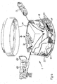
- in axonometrischer, teilweise geschnittener Ansicht mit Explosionsdarstellung einen Rauchwarnmelder entsprechend Fig. 1
- Fig. 5
- ein Blockdiagramm mit Prüfeinrichtungen eines erfindungsgemäßen Rauchwarnmelders im Ausführungsbeispiel und
- Fig. 6
- einen Datensammler zum Betrieb mit einem erfindungsgemäßen Rauchwarnmelder.
- Fig. 1
- in a schematic plan view of a smoke detector according to the invention in the embodiment with a ring-measuring element for testing the smoke-penetrating ability,
- FIGS. 2 and 3
- Views of ring gauges,
- Fig. 4
- in axonometric, partially sectioned view with exploded view of a smoke alarm according to FIG. 1
- Fig. 5
- a block diagram with testing equipment of a smoke detector according to the invention in the embodiment and
- Fig. 6
- a data collector for operation with a smoke detector according to the invention.
Fig. 1 und 4 zeigen im Ausführungsbeispiel einen erfindungsgemäßen Rauchwarnmelder 1 mit einem im Grundquerschnitt kreiszylindrischen flachen zweiteiligen Gehäuse 11. Das Gehäuse 11 weist gleichmäßig über den Umfang verteilt Öffnungsschlitze 21 auf, die durch Stege 12 in Umfangsschlitze unterteilt werden, die sich jeweils über ein Achtel des Umfangs erstrecken. Zweckmäßig sind mehrere solcher Schlitze 21, zum Beispiel drei, über die flache Gehäusehöhe des Rauchwarnmelders 1 angeordnet. Zum Inneren des Rauchwarnmelders 1 hin betrachtet, ist unmittelbar hinter den Umfangs-Öffnungsschlitzen 21 ein relativ feinmaschiger Verunreinigungsfilter 22 angeordnet, der den gesamten Öffnungsbereich der Schlitze 21 über Umfang und Höhe (=Breite) abdeckt.The
Im Inneren des Rauchwarnmelders 1 ist eine herkömmliche Rauchsensoreinrichtung 5 angeordnet. Gehäuseinnenteile des Rauchwarnmelders 1 bilden ein die Rauchsensoreinrichtung 5 umgebendes Labyrinth 41. Dieses stellt sicher, dass von außen einfallendes Fremdlicht L nicht in eine optische Dunkelkammer 4 gelangen kann und dort kein Licht von Gehäusewänden reflektiert wird, während Rauch R bis in die Kammer 4 dringt.Inside the
Die Rauchsensoreinrichtung 5 weist eine Infrarot-Leuchtdiode (Sendediode) 51 sowie eine Fotodiode (Empfängerdiode) 52 sowie eine Reflektionswand 53 auf. Mit diesen Elementen arbeitet die Rauchsensoreinrichtung 5 im Streulichtverfahren. Reine Luft reflektiert kein Licht. Befinden sich aber Rauchpartikel 54 in der optischen Kammer 4, dann wird ein Teil des von der Diode 51 abgegebenen Lichts gestreut, so dass ein Teil des Lichts die Diode 52 erreichen kann, wodurch mittels einer elektronischen Schaltung 50 der Rauchsensoreinrichtung 5 ein Alarm-/Tongeber 61 (Fig. 5) ausgelöst wird.The
Im Ausführungsbeispiel der Fig. 1 und 4 und 5 ist eine erfindungsgemäße Prüfeinrichtung 3 ausgebildet, die unabhängig von dem Vorhandensein von Rauch die Durchlässigkeit für Rauch in dem Durchlassbereich der Gehäuseöffnungen 21 und des Verunreinigungs-/Staubfilters 22 feststellt. Die Durchlass-Prüfeinrichtung 3 umfasst ein erstes Messelement 31 und ein zweites Messelement 32. Das erste Messelement 31 wird durch ein kreisförmiges offenes Ringelement gebildet. Dieses ist in Fig. 2 in Seitenansicht dargestellt. Es ist so bemessen, dass es im Bereich zwischen dem Filter 22 und der äußeren Wand 42 des Labyrinths unmittelbar in geringem Abstand neben der Innenseite des Filters 22 angeordnet ist. Wie aus Fig. 1 und 2 ersichtlich, sind Ringelemente aus einfachen Körpern in Form einer offenen Ringleitung für Licht gebildet. Diese Ringleitung kann zweckmäßig aus Kunststofffaser, z. B. Polyamidfasern hergestellt sein. Zum Beispiel kann ein Abschnitt einer Leine, einer Schnur oder eines Strangs aus einem solchen Kunststoff in die passende Ringform gebracht werden. Das Kunststoffmaterial ist transparent und lichtleitend. Von Bedeutung ist, dass das Ringelement 31 an seinem Umfang im Winkel auftreffendes Licht L durch Lichtbrechung aufnimmt und in dem Ring zu Lichtaustrittsflächen 310 an seinen offenen Enden weiterleitet. Diese Lichtaustrittsflächen 310 befinden sich an senkrecht abgebogenen offenen Ringenden, und sie sind dem in einem Dunkelraum angeordneten Lichtmesselement 32 zugewandt. Dieses wird durch einen elektro-optischen Lichtempfänger gebildet. Zum Beispiel kann ein lichtempfindliches Halbleiterelement, eine Fotodiode oder ein entsprechendes auf Licht reagierendes elektro-optisches Bauteil vorgesehen sein. Das Lichtempfangselement 32 ist mit einer elektronischen Signalverarbeitungs- und Steuerschaltung 8 verbunden, wie dies schematisch in Fig. 5 dargestellt ist.In the embodiment of Figs. 1 and 4 and 5, a
Die Ringelemente 31 eignen sich zum Einbau in die Gehäuse von herkömmlichen Rauchwarnmeldern. Der Lichtleiterstrang, der zum Beispiel einen Durchmesser von ca. 2 mm aufweist, erfasst zuverlässig den Lichtbereich von Schlitzöffnungen 21, der quer zur Umfangserstreckung des Elements 31 wesentlich, z. B. ca. sechsfach größer als der Durchmesser des Elements 31 sein kann. Man erkennt, dass durch das Element 31 keine nennenswerte Störung oder Behinderung des Raucheinlassweges erfolgt. Gemäß Fig. 2 ist ein einfach geformter Ring ausgebildet. Sollte die Breite des Raucheinlasses 2 in der Höhe des Rauchwarnmelders 1 relativ groß sein oder sollte es erforderlich sein, auch sehr geringe Lichtintensitäten und/oder Licht aus unterschiedlichen Richtungen zu erfassen und festzustellen, so kann, wie dies in Fig. 3 und 4 dargestellt ist, der Lichtleiterring in der Breitendimension des Raucheinlasses 2 Ausformungen zum Beispiel in Wellenform erhalten, um die Lichtaufnahme zu erhöhen. Auch zum Herstellen eines solchen Ringelements eignet sich ein Faserstrang aus Polyamid oder einem anderen geeigneten lichtleitenden Kunststoff, der zur Formgebung insbesondere plastisch verformt werden kann. Zur Lichtleitung kommt jedes andere Material in Betracht, das in der Lage ist, Licht längs eines aus dem Material gebildeten Körpers einzufangen und zu wenigstens einer Austrittsfläche zu leiten. Soweit diesen Anforderungen entsprochen wird, sind zum Beispiel auch Messelementkörper aus Glasfasermaterial denkbar.The
Letztlich werden Form und Charakteristik von Licht aufnehmenden und leitenden Messelementen der Prüfeinrichtung 3 nach der Bauart und der Bauform eines Rauchwarnmelders bestimmt. So kommen statt der beschriebenen Ringausbildung, die sehr vorteilhaft und zweckmäßig ist, auch andere Licht aufnehmende, sammelnde und/oder leitende Elemente wie zum Beispiel stäbchenförmige Elemente, Linsen und Prismen in Betracht. In diesen Fällen wird das aufgenommene bzw. gesammelte Licht zu einem oder mehreren Lichtempfangselementen 32 in einem Dunkelraum in dem Meldergehäuse 11 des Rauchwarnmelders 1 geleitet.Finally, the shape and characteristics of light-receiving and conductive measuring elements of the
Zum Beispiel können auch Licht-Aufnahmeelemente in Fächeranordnung mit auf den Raucheinlass ausgerichteter offener Fächerseite und mit dem Lichtempfänger zugewandter geschlossener Fächerseite vorgesehen sein. Je nach Ausbildung des Rauchwarnmelders sind unterschiedliche angepasste Anordnungen denkbar. Dabei ist es erfindungsgemäß auch möglich, wenigstens Teile von Wänden der Rauchdurchlassöffnungen und/oder des Verunreinigungs-/Staubgitters als lichtleitende Elemente auszubilden, diese also in die Öffnungswände oder den Filter zu integrieren. Auch können andere Teile des Gehäuses als lichtleitende Elemente im Bereich des Raucheinlasses 2 ausgebildet sein.For example, light receiving elements may also be provided in a fan arrangement with an open fan side aligned with the smoke inlet and with a closed fan side facing the light receiver. Depending on the design of the smoke detector different adapted arrangements are conceivable. In this case, it is also possible according to the invention to form at least parts of walls of the smoke passage openings and / or of the contamination / dust grid as light-conducting elements, ie to integrate these into the opening walls or the filter. Also, other parts of the housing may be formed as light-conducting elements in the region of the smoke inlet 2.
Die in Fig. 2 und 3 dargestellten Ring-Messelemente 31 können auch als Elemente ausgebildet sein, die ihren elektrischen Widerstand bei Lichtbestrahlung ändern. Die Ringe arbeiten dann direkt als Lichtaufnahme- und Empfangselemente, so dass sie ohne zusätzliche Empfangselemente genutzt und ihre durch Widerstandsänderung entstehenden Signale direkt einer elektronischen Signalverarbeitungs- und Steuerschaltung 8 zugeführt werden können. Auch können wenigstens Teile der Gehäusewände der Raucheinlassöffnungen und/oder Teile eines Verunreinungs-Staubfilters 22 aus auf Licht reagierenden Widerstandselementen gebildet sein, um die Lichtmessung, die den Einlass und Durchlass von Rauch in dem Rauchwarnmelder repräsentiert, durchzuführen.The
Fig. 5 zeigt in einem Blockschaltbild ein Ausführungsbeispiel für einen erfindungsgemäßen Rauchwarnmelder 1, der mit der Durchlass-Prüfeinrichtung 3 und weiteren Prüfeinrichtungen ausgestattet ist, nämlich einer Akustik-Prüfeinrichtung 6, einer Installations-Prüfeinrichtung 71, einer Stromversorgungs- und Prüfeinrichtung 72 und einer Selbsttestdiagnose-Prüfeinrichtung 73. Der Rauchwarnmelder 1 ist auch mit einer elektronischen Signalverarbeitungs- und Steuerschaltung 8, die gemessene Signale auswertet, einer Speichereinrichtung 81 und einer Funk-Datenübertragungseinrichtung 82 ausgestattet. In Fig. 4 sind elektronische Baumodule für die elektronischen Einrichtungen 3 und 82 zu sehen. Die Einrichtung 82 ist mit einer Sende-/Empfangsantenne 83 versehen. Nicht zu sehende Module für die anderen Einrichtungen sind ebenfalls in dem Gehäuse 11 untergebracht. Die Stromversorgung 72 umfasst eine Batterie.Fig. 5 shows in a block diagram an embodiment of a
Ein Test-/Prüfbetrieb wird durch ein Programm der Signalverarbeitungs- und Steuerschaltung 8 gestartet. Eine solche Elektronik wird in Form einer zentralen Steuerlogik mit CPU bereitgestellt. Jede andere geeignete Schaltungs-, Programm- und Steuerlogik kann eingesetzt werden. Zunächst testet das Prüfprogramm die Durchlass-Prüfeinrichtung 3. Die Intensität des mit den Messelementen 31 und 32 erfassten Lichts wird gemessen und mit einem gespeicherten geeichten Wert verglichen. Das Vergleichsergebnis wird an die Schaltung 8 geführt und in der Speichereinrichtung 81 gespeichert. Das Programm führt zudem einen Test der Akustik-Prüfeinrichtung 6 durch. Ein Prüfgenerator 63 erzeugt ein nieder- oder hochfrequentes Signal, das auf einen Alarm-/Tongeber 61 gegeben und von einem Mikrofon 62 empfangen wird. Das damit aufgenommene Signal wird über die Einrichtung 6 an die Schaltung 8 gegeben, die der Speichereinrichtung 81 einen entsprechenden, den Funktionsstatus repräsentierenden Wert zuführt.A test / test operation is started by a program of the signal processing and
Die Installations-Prüfeinrichtung 71 ist vorgesehen, um die korrekte Anbringungsposition des Rauchwarnmelders 1 zu prüfen. Die korrekte Anbringung an einer Gebäudedecke oder -wand wird mittels eines nicht dargestellten Schaltkontaktes des Rauchwarnmelders 1 festgestellt. Zum Beispiel kann an dem Meldergehäuse 11 ein federbelasteter elektrischer Schalter eingerichtet sein, dessen Kontakt unterbrochen wird, wenn die Federbelastung durch Abnahme des Melders 1 von Wand oder Decke entfällt. Auch der Zustand des Schalters wird, im Ablauf durch das steuernde Prüfprogramm, durch die Schaltung 8 verarbeitet und der Speichereinrichtung 81 zugeführt.The
Weiterhin umfasst der Rauchwarnmelder die Selbsttestdiagnose-Prüfeinrichtung 73, die im Ausführungsbeispiel die Funktion der Rauchsensoreinrichtung 5 testet. Gleichermaßen können Selbstdiagnose-Einrichtungen für die Funktionen der vorgenannten Prüfeinrichtungen vorgesehen sein. Schließlich ist der Melder 1 noch mit der Stromversorgungs- und Prüfeinrichtung 73 zum Prüfen der Stromversorgung für sämtliche Einrichtungen ausgestattet. Die elektronische Signalverarbeitungs- und Steuerschaltung 8 wertet die einzelnen Messergebnisse und Signale aus und führt die Auswertungsergebnisse der Speichereinrichtung 81 zu. Die Schaltung 8 berücksichtigt zum Programmbetrieb und bei der Auswertung Zeit und Kalenderdaten.Furthermore, the smoke alarm device comprises the self-test
Die Übertragungseinrichtung 82 (Funkmodul) wird zweckmäßig in Form eines an sich bekannten Transponders eingerichtet. Solche Transponder sind zum Beispiel zur Verbrauchsdatenerfassung bekannt. Geeignete Transponder werden zum Beispiel in
Die Einrichtung 82 bzw. der Transponder arbeiten mit einem in Fig. 6 dargestellten Datensammler 9 zusammen. Datensammler 9 und Transponder 82 korrespondieren über Funksignale jeweils von Sender und Empfänger miteinander. Dabei werden dem Datensammler 9 mehrere Rauchwarnmelder 1 einer Wohn- oder Gebäudeeinheit zugeordnet.The
Wenn alle Ergebnisse einer Prüfung eines Rauchwarnmelders 1 in dem Speicher 81 gespeichert worden sind, werden die gespeicherten Daten an den empfangsbereiten Datensammler 9 sofort oder zu vorbestimmter Zeit übertragen. In dem Datensammler 9 wird zum Beispiel das in Fig. 6 wiedergegebene Protokoll zu einem Rauchwarnmelder 1 erstellt. Dies erfasst zur Geräteidentifikation in der Speichereinrichtung 81 auch bereitgehaltene charakteristische Rauchwarnmelder-Daten wie Ortsangabe, Gerätenummer und Montagedatum.When all the results of a check of a
Zweckmäßig wird das Steuerprogramm der Schaltung 8 so eingerichtet, dass die Prüfung verteilt über einen Tag mehrmals, zum Beispiel drei mal durchgeführt wird, um sicherzustellen, dass zumindest in einem Zeitfenster für eine deutlich erfassbare und differenzierbare Messung genügend Licht zur Verfügung steht. Befindet sich nur eines der ausgewerteten Ergebnisse außerhalb einer vorgeschriebenen, mit der Schaltung 8 berücksichtigten Toleranz, wird dies im Protokoll sichtbar. Nachdem das Protokoll im Datensammler 9 erstellt worden ist, wird der Prüfvorgang durch das Test- und Prüfprogramm beendet und zum nächsten programmierten Termin wieder ausgelöst. Selbstverständlich kann das Test-/Prüfprogramm im Rauchwarnmelder 1 auch durch den Datensammler 9 ausgelöst werden.Suitably, the control program of the
Auch dem Datensammler 9 kommt eine Prüffunktion zu. So wird dieser bei der Installation mit charakteristischen Daten von einzelnen zugeordneten Rauchwarnmeldern versorgt. Die Test-/Prüfprogramme einer Serie von Rauchwarnmeldern 1 in einer Wohn-/Gebäudeeinheit werden zeitlich aufeinander abgestimmt. Wenn im Rahmen dieses Vorgangs nun ein neues Protokoll erstellt wird, so prüft der Datensammler 9 in der Folge, ob die Daten von der Gruppe der vorgemerkten Geräte übertragen werden. Fehlt die Datenübertragung eines Rauchwarnmelders der Gruppe, so wird dies als Totalausfall des betreffenden Rauchwarnmelders im Protokoll verzeichnet. Ein Protokoll, das auf diese Weise mit den erfindungsgemäßen Einrichtungen erstellt worden ist, wird mindestens einmal jährlich ausgelesen. Wenn dann festgestellt werden sollte, dass ein Rauchwammelder oder mehrere Rauchwarnmelder mit der einen oder anderen Funktionsstörung behaftet sind, wird ein Servicetechniker beauftragt, den identifizierten Rauchwarnmelder zu inspizieren, die Störung zu beheben und gegebenenfalls einen Geräteaustausch vorzunehmen. Man erkennt, dass insbesondere Ortsbegehungen, die herkömmlich zur Prüfung der Raucheindringfähigkeit erforderlich gewesen sind, durch die erfindungsgemäßen Maßnahmen entfallen.Also, the
Claims (24)
Priority Applications (3)
| Application Number | Priority Date | Filing Date | Title |
|---|---|---|---|
| EP06090117A EP1870866B1 (en) | 2006-06-24 | 2006-06-24 | Smoke alarm device |
| DE502006006707T DE502006006707D1 (en) | 2006-06-24 | 2006-06-24 | Smoke detectors |
| AT06090117T ATE464629T1 (en) | 2006-06-24 | 2006-06-24 | SMOKE ALARM |
Applications Claiming Priority (1)
| Application Number | Priority Date | Filing Date | Title |
|---|---|---|---|
| EP06090117A EP1870866B1 (en) | 2006-06-24 | 2006-06-24 | Smoke alarm device |
Publications (2)
| Publication Number | Publication Date |
|---|---|
| EP1870866A1 true EP1870866A1 (en) | 2007-12-26 |
| EP1870866B1 EP1870866B1 (en) | 2010-04-14 |
Family
ID=37434040
Family Applications (1)
| Application Number | Title | Priority Date | Filing Date |
|---|---|---|---|
| EP06090117A Not-in-force EP1870866B1 (en) | 2006-06-24 | 2006-06-24 | Smoke alarm device |
Country Status (3)
| Country | Link |
|---|---|
| EP (1) | EP1870866B1 (en) |
| AT (1) | ATE464629T1 (en) |
| DE (1) | DE502006006707D1 (en) |
Cited By (9)
| Publication number | Priority date | Publication date | Assignee | Title |
|---|---|---|---|---|
| DE102008014991B3 (en) * | 2008-03-19 | 2009-03-12 | Job Lizenz Gmbh & Co. Kg | Gas inflow checking method for alarm device i.e. smoke alarm, involves measuring number of oscillations of acoustic signals after completion of production of acoustic signals, and comparing number of oscillations with preset value |
| EP2104078A2 (en) * | 2008-03-19 | 2009-09-23 | Ista International GmbH | Smoke alarm device |
| EP2189956A1 (en) | 2008-11-21 | 2010-05-26 | Hekatron Vertriebs GmbH | Fire alarm and method for detecting pollution |
| DE102015004458A1 (en) | 2014-06-26 | 2015-12-31 | Elmos Semiconductor Aktiengesellschaft | Apparatus and method for a classifying, smokeless air condition sensor |
| DE102014019172A1 (en) | 2014-12-17 | 2016-06-23 | Elmos Semiconductor Aktiengesellschaft | Apparatus and method for distinguishing solid objects, cooking fumes and smoke with a compensating optical measuring system |
| DE102014019773A1 (en) | 2014-12-17 | 2016-06-23 | Elmos Semiconductor Aktiengesellschaft | Apparatus and method for distinguishing solid objects, cooking fumes and smoke by means of the display of a mobile telephone |
| EP3073458A1 (en) | 2015-03-23 | 2016-09-28 | Siemens Schweiz AG | Fire alarm with a light scattering assembly in the region of a smoke entry opening for contamination monitoring |
| EP3113133A3 (en) * | 2015-06-29 | 2017-05-17 | Atral-Secal GmbH | Smoke detector with combined coverage and particle detection at the smoke inlet opening |
| EP4339914A1 (en) * | 2022-09-19 | 2024-03-20 | Atral-Secal GmbH | Device and method for operating a smoke detector |
Citations (8)
| Publication number | Priority date | Publication date | Assignee | Title |
|---|---|---|---|---|
| JPH02227800A (en) | 1989-02-28 | 1990-09-10 | Hochiki Corp | Photoelectric smoke sensor |
| EP0503167A1 (en) * | 1991-03-12 | 1992-09-16 | Matsushita Electric Works, Ltd. | A method for testing smoke sensor and a smoke sensor having a function of executing the test |
| WO1994018653A1 (en) * | 1993-02-15 | 1994-08-18 | Cerberus Ag | Device for testing smoke detectors |
| US5568133A (en) * | 1993-03-19 | 1996-10-22 | Cerberus Ag | Fire alarm |
| WO1998008205A1 (en) * | 1996-08-20 | 1998-02-26 | Mcbride Wilson Robert James | Improvements relating to event detection and recordal |
| US6469623B2 (en) | 2001-01-26 | 2002-10-22 | Gentex Corporation | Smoke detector maintenance and verification tool |
| WO2003067542A1 (en) * | 2002-02-06 | 2003-08-14 | No Climb Products | Method and apparatus for monitoring fire detectors |
| US20040217857A1 (en) * | 2003-04-30 | 2004-11-04 | Gary Lennartz | Smoke detector with performance reporting |
-
2006
- 2006-06-24 AT AT06090117T patent/ATE464629T1/en active
- 2006-06-24 DE DE502006006707T patent/DE502006006707D1/en active Active
- 2006-06-24 EP EP06090117A patent/EP1870866B1/en not_active Not-in-force
Patent Citations (8)
| Publication number | Priority date | Publication date | Assignee | Title |
|---|---|---|---|---|
| JPH02227800A (en) | 1989-02-28 | 1990-09-10 | Hochiki Corp | Photoelectric smoke sensor |
| EP0503167A1 (en) * | 1991-03-12 | 1992-09-16 | Matsushita Electric Works, Ltd. | A method for testing smoke sensor and a smoke sensor having a function of executing the test |
| WO1994018653A1 (en) * | 1993-02-15 | 1994-08-18 | Cerberus Ag | Device for testing smoke detectors |
| US5568133A (en) * | 1993-03-19 | 1996-10-22 | Cerberus Ag | Fire alarm |
| WO1998008205A1 (en) * | 1996-08-20 | 1998-02-26 | Mcbride Wilson Robert James | Improvements relating to event detection and recordal |
| US6469623B2 (en) | 2001-01-26 | 2002-10-22 | Gentex Corporation | Smoke detector maintenance and verification tool |
| WO2003067542A1 (en) * | 2002-02-06 | 2003-08-14 | No Climb Products | Method and apparatus for monitoring fire detectors |
| US20040217857A1 (en) * | 2003-04-30 | 2004-11-04 | Gary Lennartz | Smoke detector with performance reporting |
Cited By (11)
| Publication number | Priority date | Publication date | Assignee | Title |
|---|---|---|---|---|
| DE102008014991B3 (en) * | 2008-03-19 | 2009-03-12 | Job Lizenz Gmbh & Co. Kg | Gas inflow checking method for alarm device i.e. smoke alarm, involves measuring number of oscillations of acoustic signals after completion of production of acoustic signals, and comparing number of oscillations with preset value |
| EP2104079A1 (en) | 2008-03-19 | 2009-09-23 | Job Lizenz GmbH & Co. KG | Method and warning device, in particular smoke alarm |
| EP2104078A2 (en) * | 2008-03-19 | 2009-09-23 | Ista International GmbH | Smoke alarm device |
| EP2104078A3 (en) * | 2008-03-19 | 2012-06-13 | ista International GmbH | Smoke alarm device |
| EP2189956A1 (en) | 2008-11-21 | 2010-05-26 | Hekatron Vertriebs GmbH | Fire alarm and method for detecting pollution |
| DE102015004458A1 (en) | 2014-06-26 | 2015-12-31 | Elmos Semiconductor Aktiengesellschaft | Apparatus and method for a classifying, smokeless air condition sensor |
| DE102014019172A1 (en) | 2014-12-17 | 2016-06-23 | Elmos Semiconductor Aktiengesellschaft | Apparatus and method for distinguishing solid objects, cooking fumes and smoke with a compensating optical measuring system |
| DE102014019773A1 (en) | 2014-12-17 | 2016-06-23 | Elmos Semiconductor Aktiengesellschaft | Apparatus and method for distinguishing solid objects, cooking fumes and smoke by means of the display of a mobile telephone |
| EP3073458A1 (en) | 2015-03-23 | 2016-09-28 | Siemens Schweiz AG | Fire alarm with a light scattering assembly in the region of a smoke entry opening for contamination monitoring |
| EP3113133A3 (en) * | 2015-06-29 | 2017-05-17 | Atral-Secal GmbH | Smoke detector with combined coverage and particle detection at the smoke inlet opening |
| EP4339914A1 (en) * | 2022-09-19 | 2024-03-20 | Atral-Secal GmbH | Device and method for operating a smoke detector |
Also Published As
| Publication number | Publication date |
|---|---|
| ATE464629T1 (en) | 2010-04-15 |
| EP1870866B1 (en) | 2010-04-14 |
| DE502006006707D1 (en) | 2010-05-27 |
Similar Documents
| Publication | Publication Date | Title |
|---|---|---|
| EP1870866B1 (en) | Smoke alarm device | |
| DE102006023048C5 (en) | Fire alarm and method for checking its functionality | |
| EP2028631B1 (en) | Smoke detector with contamination monitoring | |
| DE102005060748B3 (en) | Fire warning alarm unit e.g. smoke warning alarm unit, flame alarm unit for use in houses and commercial areas has memory for storing self-testing results which are also sent by transmitter to receiver | |
| EP3274975A1 (en) | Fire detector with a scattered light arrangement in the region of a smoke inlet opening for monitoring pollution | |
| DE102013003614B4 (en) | Device for detecting smoke in a room and method for checking the functionality of such a device | |
| EP2320399B1 (en) | Hazard alarm | |
| DE4240395C2 (en) | Detector for the detection of electromagnetic radiation | |
| DE19951403A1 (en) | Device for detecting smoke | |
| EP1039426A2 (en) | Smoke sensing device | |
| EP2330577A1 (en) | Smoke alarm with infrared coverage monitoring | |
| EP3096130B1 (en) | Device for identification of aerosols | |
| EP2333737A1 (en) | Hazard warning system with method for recognising objects in the vicinity of same | |
| EP3113133B1 (en) | Smoke detector with combined coverage and particle detection at the smoke inlet opening | |
| DE102018000292A1 (en) | Smoke detector and method for detecting soiling or covering a smoke detector | |
| DE102009054141A1 (en) | Method for verifying proper function of smoke detector in inner room of building, involves comparing output signal with reference output signal, and outputting error signal, when output signal falls below reference output signal | |
| WO2014180773A1 (en) | Fire alarm | |
| EP2908297B1 (en) | Linear fire alarm and method for operating same | |
| WO2003102889A1 (en) | Fire detector and fire detection system | |
| EP1818884B1 (en) | Smoke detecting apparatus | |
| DE20023533U1 (en) | Smoke detector with transmitter and receiver in housing inserted in ceiling, to emit beam for reflection off smoke | |
| DE102006006418A1 (en) | Smoke detection device | |
| DE102010002295A1 (en) | Fire alarm for monitoring system in building center, has fire alarm and room monitoring modules arranged in cabinets and including evaluation units and sensors, where modules are functionally operated and interchanged from each other | |
| DE3328043A1 (en) | SMOKE DETECTOR ARRANGEMENT WORKING ACCORDING TO THE EXTINCTION PRINCIPLE AND FIRE DETECTING SYSTEM WITH SUCH A SMOKE DETECTOR ARRANGEMENT | |
| DE102008006146A1 (en) | Device for obscuration measurement in monitoring area at road in tunnel, has evaluation unit for selecting light-sensitive pixel element of matrix image sensor, where light source lies in receiving area of element |
Legal Events
| Date | Code | Title | Description |
|---|---|---|---|
| PUAI | Public reference made under article 153(3) epc to a published international application that has entered the european phase |
Free format text: ORIGINAL CODE: 0009012 |
|
| AK | Designated contracting states |
Kind code of ref document: A1 Designated state(s): AT BE BG CH CY CZ DE DK EE ES FI FR GB GR HU IE IS IT LI LT LU LV MC NL PL PT RO SE SI SK TR |
|
| AX | Request for extension of the european patent |
Extension state: AL BA HR MK YU |
|
| 17P | Request for examination filed |
Effective date: 20080621 |
|
| 17Q | First examination report despatched |
Effective date: 20080728 |
|
| AKX | Designation fees paid |
Designated state(s): AT BE BG CH CY CZ DE DK EE ES FI FR GB GR HU IE IS IT LI LT LU LV MC NL PL PT RO SE SI SK TR |
|
| GRAP | Despatch of communication of intention to grant a patent |
Free format text: ORIGINAL CODE: EPIDOSNIGR1 |
|
| GRAS | Grant fee paid |
Free format text: ORIGINAL CODE: EPIDOSNIGR3 |
|
| GRAA | (expected) grant |
Free format text: ORIGINAL CODE: 0009210 |
|
| AK | Designated contracting states |
Kind code of ref document: B1 Designated state(s): AT BE BG CH CY CZ DE DK EE ES FI FR GB GR HU IE IS IT LI LT LU LV MC NL PL PT RO SE SI SK TR |
|
| REG | Reference to a national code |
Ref country code: GB Ref legal event code: FG4D Free format text: NOT ENGLISH |
|
| REG | Reference to a national code |
Ref country code: CH Ref legal event code: EP |
|
| REG | Reference to a national code |
Ref country code: IE Ref legal event code: FG4D Free format text: LANGUAGE OF EP DOCUMENT: GERMAN |
|
| REG | Reference to a national code |
Ref country code: CH Ref legal event code: NV Representative=s name: E. BLUM & CO. AG PATENT- UND MARKENANWAELTE VSP |
|
| REF | Corresponds to: |
Ref document number: 502006006707 Country of ref document: DE Date of ref document: 20100527 Kind code of ref document: P |
|
| REG | Reference to a national code |
Ref country code: NL Ref legal event code: VDEP Effective date: 20100414 |
|
| LTIE | Lt: invalidation of european patent or patent extension |
Effective date: 20100414 |
|
| PG25 | Lapsed in a contracting state [announced via postgrant information from national office to epo] |
Ref country code: LT Free format text: LAPSE BECAUSE OF FAILURE TO SUBMIT A TRANSLATION OF THE DESCRIPTION OR TO PAY THE FEE WITHIN THE PRESCRIBED TIME-LIMIT Effective date: 20100414 Ref country code: SE Free format text: LAPSE BECAUSE OF FAILURE TO SUBMIT A TRANSLATION OF THE DESCRIPTION OR TO PAY THE FEE WITHIN THE PRESCRIBED TIME-LIMIT Effective date: 20100414 Ref country code: NL Free format text: LAPSE BECAUSE OF FAILURE TO SUBMIT A TRANSLATION OF THE DESCRIPTION OR TO PAY THE FEE WITHIN THE PRESCRIBED TIME-LIMIT Effective date: 20100414 Ref country code: ES Free format text: LAPSE BECAUSE OF FAILURE TO SUBMIT A TRANSLATION OF THE DESCRIPTION OR TO PAY THE FEE WITHIN THE PRESCRIBED TIME-LIMIT Effective date: 20100725 |
|
| REG | Reference to a national code |
Ref country code: IE Ref legal event code: FD4D |
|
| PG25 | Lapsed in a contracting state [announced via postgrant information from national office to epo] |
Ref country code: SI Free format text: LAPSE BECAUSE OF FAILURE TO SUBMIT A TRANSLATION OF THE DESCRIPTION OR TO PAY THE FEE WITHIN THE PRESCRIBED TIME-LIMIT Effective date: 20100414 Ref country code: LV Free format text: LAPSE BECAUSE OF FAILURE TO SUBMIT A TRANSLATION OF THE DESCRIPTION OR TO PAY THE FEE WITHIN THE PRESCRIBED TIME-LIMIT Effective date: 20100414 Ref country code: IS Free format text: LAPSE BECAUSE OF FAILURE TO SUBMIT A TRANSLATION OF THE DESCRIPTION OR TO PAY THE FEE WITHIN THE PRESCRIBED TIME-LIMIT Effective date: 20100814 Ref country code: FI Free format text: LAPSE BECAUSE OF FAILURE TO SUBMIT A TRANSLATION OF THE DESCRIPTION OR TO PAY THE FEE WITHIN THE PRESCRIBED TIME-LIMIT Effective date: 20100414 |
|
| BERE | Be: lapsed |
Owner name: BRUNATA WARMEMESSER HAGEN G.M.B.H. & CO. KG Effective date: 20100630 |
|
| PG25 | Lapsed in a contracting state [announced via postgrant information from national office to epo] |
Ref country code: PL Free format text: LAPSE BECAUSE OF FAILURE TO SUBMIT A TRANSLATION OF THE DESCRIPTION OR TO PAY THE FEE WITHIN THE PRESCRIBED TIME-LIMIT Effective date: 20100414 Ref country code: CY Free format text: LAPSE BECAUSE OF FAILURE TO SUBMIT A TRANSLATION OF THE DESCRIPTION OR TO PAY THE FEE WITHIN THE PRESCRIBED TIME-LIMIT Effective date: 20100519 Ref country code: GR Free format text: LAPSE BECAUSE OF FAILURE TO SUBMIT A TRANSLATION OF THE DESCRIPTION OR TO PAY THE FEE WITHIN THE PRESCRIBED TIME-LIMIT Effective date: 20100715 |
|
| PG25 | Lapsed in a contracting state [announced via postgrant information from national office to epo] |
Ref country code: PT Free format text: LAPSE BECAUSE OF FAILURE TO SUBMIT A TRANSLATION OF THE DESCRIPTION OR TO PAY THE FEE WITHIN THE PRESCRIBED TIME-LIMIT Effective date: 20100816 Ref country code: IE Free format text: LAPSE BECAUSE OF FAILURE TO SUBMIT A TRANSLATION OF THE DESCRIPTION OR TO PAY THE FEE WITHIN THE PRESCRIBED TIME-LIMIT Effective date: 20100414 Ref country code: MC Free format text: LAPSE BECAUSE OF NON-PAYMENT OF DUE FEES Effective date: 20100630 Ref country code: EE Free format text: LAPSE BECAUSE OF FAILURE TO SUBMIT A TRANSLATION OF THE DESCRIPTION OR TO PAY THE FEE WITHIN THE PRESCRIBED TIME-LIMIT Effective date: 20100414 Ref country code: DK Free format text: LAPSE BECAUSE OF FAILURE TO SUBMIT A TRANSLATION OF THE DESCRIPTION OR TO PAY THE FEE WITHIN THE PRESCRIBED TIME-LIMIT Effective date: 20100414 |
|
| PLBE | No opposition filed within time limit |
Free format text: ORIGINAL CODE: 0009261 |
|
| STAA | Information on the status of an ep patent application or granted ep patent |
Free format text: STATUS: NO OPPOSITION FILED WITHIN TIME LIMIT |
|
| PG25 | Lapsed in a contracting state [announced via postgrant information from national office to epo] |
Ref country code: CZ Free format text: LAPSE BECAUSE OF FAILURE TO SUBMIT A TRANSLATION OF THE DESCRIPTION OR TO PAY THE FEE WITHIN THE PRESCRIBED TIME-LIMIT Effective date: 20100414 Ref country code: RO Free format text: LAPSE BECAUSE OF FAILURE TO SUBMIT A TRANSLATION OF THE DESCRIPTION OR TO PAY THE FEE WITHIN THE PRESCRIBED TIME-LIMIT Effective date: 20100414 Ref country code: SK Free format text: LAPSE BECAUSE OF FAILURE TO SUBMIT A TRANSLATION OF THE DESCRIPTION OR TO PAY THE FEE WITHIN THE PRESCRIBED TIME-LIMIT Effective date: 20100414 |
|
| REG | Reference to a national code |
Ref country code: FR Ref legal event code: ST Effective date: 20110228 |
|
| 26N | No opposition filed |
Effective date: 20110117 |
|
| GBPC | Gb: european patent ceased through non-payment of renewal fee |
Effective date: 20100714 |
|
| PG25 | Lapsed in a contracting state [announced via postgrant information from national office to epo] |
Ref country code: IT Free format text: LAPSE BECAUSE OF FAILURE TO SUBMIT A TRANSLATION OF THE DESCRIPTION OR TO PAY THE FEE WITHIN THE PRESCRIBED TIME-LIMIT Effective date: 20100414 |
|
| PG25 | Lapsed in a contracting state [announced via postgrant information from national office to epo] |
Ref country code: FR Free format text: LAPSE BECAUSE OF NON-PAYMENT OF DUE FEES Effective date: 20100630 |
|
| PG25 | Lapsed in a contracting state [announced via postgrant information from national office to epo] |
Ref country code: BE Free format text: LAPSE BECAUSE OF NON-PAYMENT OF DUE FEES Effective date: 20100630 |
|
| PG25 | Lapsed in a contracting state [announced via postgrant information from national office to epo] |
Ref country code: GB Free format text: LAPSE BECAUSE OF NON-PAYMENT OF DUE FEES Effective date: 20100714 |
|
| PGFP | Annual fee paid to national office [announced via postgrant information from national office to epo] |
Ref country code: CH Payment date: 20110623 Year of fee payment: 6 |
|
| PGFP | Annual fee paid to national office [announced via postgrant information from national office to epo] |
Ref country code: AT Payment date: 20110620 Year of fee payment: 6 |
|
| PGFP | Annual fee paid to national office [announced via postgrant information from national office to epo] |
Ref country code: DE Payment date: 20110629 Year of fee payment: 6 |
|
| PG25 | Lapsed in a contracting state [announced via postgrant information from national office to epo] |
Ref country code: BG Free format text: LAPSE BECAUSE OF FAILURE TO SUBMIT A TRANSLATION OF THE DESCRIPTION OR TO PAY THE FEE WITHIN THE PRESCRIBED TIME-LIMIT Effective date: 20100414 Ref country code: LU Free format text: LAPSE BECAUSE OF NON-PAYMENT OF DUE FEES Effective date: 20100624 Ref country code: HU Free format text: LAPSE BECAUSE OF FAILURE TO SUBMIT A TRANSLATION OF THE DESCRIPTION OR TO PAY THE FEE WITHIN THE PRESCRIBED TIME-LIMIT Effective date: 20101015 |
|
| PG25 | Lapsed in a contracting state [announced via postgrant information from national office to epo] |
Ref country code: TR Free format text: LAPSE BECAUSE OF FAILURE TO SUBMIT A TRANSLATION OF THE DESCRIPTION OR TO PAY THE FEE WITHIN THE PRESCRIBED TIME-LIMIT Effective date: 20100414 |
|
| REG | Reference to a national code |
Ref country code: CH Ref legal event code: PL |
|
| REG | Reference to a national code |
Ref country code: CH Ref legal event code: PL Ref country code: AT Ref legal event code: MM01 Ref document number: 464629 Country of ref document: AT Kind code of ref document: T Effective date: 20120624 |
|
| REG | Reference to a national code |
Ref country code: DE Ref legal event code: R119 Ref document number: 502006006707 Country of ref document: DE Effective date: 20130101 |
|
| PG25 | Lapsed in a contracting state [announced via postgrant information from national office to epo] |
Ref country code: CH Free format text: LAPSE BECAUSE OF NON-PAYMENT OF DUE FEES Effective date: 20120630 Ref country code: LI Free format text: LAPSE BECAUSE OF NON-PAYMENT OF DUE FEES Effective date: 20120630 Ref country code: DE Free format text: LAPSE BECAUSE OF NON-PAYMENT OF DUE FEES Effective date: 20130101 |
|
| PG25 | Lapsed in a contracting state [announced via postgrant information from national office to epo] |
Ref country code: AT Free format text: LAPSE BECAUSE OF NON-PAYMENT OF DUE FEES Effective date: 20120624 |
|
| PG25 | Lapsed in a contracting state [announced via postgrant information from national office to epo] |
Ref country code: BG Free format text: LAPSE BECAUSE OF FAILURE TO SUBMIT A TRANSLATION OF THE DESCRIPTION OR TO PAY THE FEE WITHIN THE PRESCRIBED TIME-LIMIT Effective date: 20100714 |