EP1870781A1 - A roller for a printer and a method of cooling the roller surface - Google Patents
A roller for a printer and a method of cooling the roller surface Download PDFInfo
- Publication number
- EP1870781A1 EP1870781A1 EP07110015A EP07110015A EP1870781A1 EP 1870781 A1 EP1870781 A1 EP 1870781A1 EP 07110015 A EP07110015 A EP 07110015A EP 07110015 A EP07110015 A EP 07110015A EP 1870781 A1 EP1870781 A1 EP 1870781A1
- Authority
- EP
- European Patent Office
- Prior art keywords
- roller
- tubular space
- blocking element
- intra
- inter
- Prior art date
- Legal status (The legal status is an assumption and is not a legal conclusion. Google has not performed a legal analysis and makes no representation as to the accuracy of the status listed.)
- Granted
Links
Images



Classifications
-
- G—PHYSICS
- G03—PHOTOGRAPHY; CINEMATOGRAPHY; ANALOGOUS TECHNIQUES USING WAVES OTHER THAN OPTICAL WAVES; ELECTROGRAPHY; HOLOGRAPHY
- G03G—ELECTROGRAPHY; ELECTROPHOTOGRAPHY; MAGNETOGRAPHY
- G03G15/00—Apparatus for electrographic processes using a charge pattern
- G03G15/75—Details relating to xerographic drum, band or plate, e.g. replacing, testing
- G03G15/751—Details relating to xerographic drum, band or plate, e.g. replacing, testing relating to drum
-
- G—PHYSICS
- G03—PHOTOGRAPHY; CINEMATOGRAPHY; ANALOGOUS TECHNIQUES USING WAVES OTHER THAN OPTICAL WAVES; ELECTROGRAPHY; HOLOGRAPHY
- G03G—ELECTROGRAPHY; ELECTROPHOTOGRAPHY; MAGNETOGRAPHY
- G03G21/00—Arrangements not provided for by groups G03G13/00 - G03G19/00, e.g. cleaning, elimination of residual charge
- G03G21/20—Humidity or temperature control also ozone evacuation; Internal apparatus environment control
- G03G21/206—Conducting air through the machine, e.g. for cooling, filtering, removing gases like ozone
-
- G—PHYSICS
- G03—PHOTOGRAPHY; CINEMATOGRAPHY; ANALOGOUS TECHNIQUES USING WAVES OTHER THAN OPTICAL WAVES; ELECTROGRAPHY; HOLOGRAPHY
- G03G—ELECTROGRAPHY; ELECTROPHOTOGRAPHY; MAGNETOGRAPHY
- G03G2221/00—Processes not provided for by group G03G2215/00, e.g. cleaning or residual charge elimination
- G03G2221/16—Mechanical means for facilitating the maintenance of the apparatus, e.g. modular arrangements and complete machine concepts
- G03G2221/1606—Mechanical means for facilitating the maintenance of the apparatus, e.g. modular arrangements and complete machine concepts for the photosensitive element
- G03G2221/1609—Mechanical means for facilitating the maintenance of the apparatus, e.g. modular arrangements and complete machine concepts for the photosensitive element protective arrangements for preventing damage
Definitions
- the invention pertains to a roller for a printer comprising an outer tube and positioned therein at least one inner tube, the outer tube extending in an axial direction from a first end to a second end and the inner tube extending substantially parallel to the outer tube, defining an inter tubular space between the outer and the inner tube and an intra tubular space within the inner tube.
- the invention also pertains to a method of cooling the surface of such a roller.
- Such rollers are commonly applied in e.g. electrophotographic printers. Rollers of this type are e.g. used as image bearing rollers or as cooling rollers. These are rollers that absorb heat in their operation and that require cooling of their surface. The cooling is usually done by blowing or sucking air through the interior of the roller with a fan.
- Image bearing rollers are e.g. rollers that are covered with a photoconductive layer or with an electrode pattern. This enables the formation of an electrostatic image on the surface of the image bearing roller.
- a layer of toner particles is developed onto the electrostatic image on the image bearing roller.
- This toner image is subsequently transferred to the receiving substrate and fused with the receiving substrate.
- the surface temperature of the image bearing roller tends to increase. If the surface temperature rises too high, the toner particles will fuse and stick to the surface of the image bearing roller resulting in print artefacts. Therefore, the surface of the image bearing roller requires cooling by e.g. blowing air through the roller. Rollers according to the preamble are also used to as cooling rollers.
- the object of the present invention is to provide a roller that has an improved cooling efficiency by reducing the temperature gradient over the roller.
- a roller according to the preamble has been devised characterised in that the roller comprises a blocking element (27) dividing the inter tubular space and the intra tubular space in a first part extending substantially from the first end to the blocking element and a second part extending substantially from the blocking element to the second end and a first and a second duct (31, 33) connecting the first and second part of the inter tubular space with the second respectively the first part of the intra tubular space via the blocking element.
- the blocking element can be a disk like object that fits into the outer tube and extends though the inner tube, dividing both the intra tubular space and the inter tubular space into a first and a second part.
- the blocking element can entirely or partially block the flow through the roller and can be e.g. an injection moulded plastic object.
- the outer tube can comprise lamellae that extend from the inner surface into the inter tubular space and stretch out along the longitudinal axis of the roller. These lamellae increase the inner surface area of the outer tube, which increases the effective contact area with the flow and thus increases the heat exchange capacity.
- the blocking element is configured such that it fits in the outer tube and has radial cuts from the outside inwards that allow the lamellae to pass through the blocking element. The size of these radial cuts can be adapted to control the fraction of the flow that is blocked and the fraction that is allowed to continue its path through the inter tubular space.
- a first and a second duct are present extending through the blocking element and connecting the inter tubular space with the intra tubular space. This allows air that is blown into any of the first and the second part of inter tubular space to pass through the duct and to exit the roller via any of the first and the second part of the intra tubular space.
- air that is blown into the any of the first and the second part of the intra tubular space can exit the roller through any of the first and the second part of the inter tubular space.
- air can be blown simultaneously into the first and the second part of the inter tubular space from both directions, using two fan units.
- the flow that is blown into the first part of the inter tubular space can exit the roller via the first part of the intra tubular space.
- the air flow that is simultaneously blown into the second part of the inter tubular space can exit the roller via the second part of the intra tubular space.
- the blocking element is positioned at a central position along the axis of the roller.
- the air that is blown through the first part of the inter tubular space and that cools the surface of the roller cools only half of the roller surface.
- the surface temperature gradient over the first part of the roller is the same as in the absence of the blocking element.
- the second part of roller surface will experience approximately the same gradient in surface temperature as in the first part resulting in a cumulative gradient in surface temperature over the entire roller surface of approximately two times the temperature gradient over the first part.
- every stream of the air is allowed to cool only half of the roller surface.
- the gradient in surface temperature over the entire roller surface is not cumulative, but rather the first part and the second part of the surface independently experience the same gradient in surface temperature.
- the extreme temperature differences over the roller surface are thus reduced by approximately a factor of two, with respect to the situation without the blocking element.
- first and the second duct each connect one of the first and the second part of the inter tubular space with the opposing first or second part of the intra tubular space.
- Air that is e.g. blown into the first part of the inter tubular space serves to cool the first part of the roller surface and exits the roller via the second part of the intra tubular space, where it does not cool the surface of the roller.
- Air that is simultaneously blown into the first part of the intra tubular space, where it does not cool the surface of the roller passes through the second duct and exits the roller via the second part of the inter tubular space where it cools the surface of the roller.
- the flow rate through the roller can be optimised by choosing a high number of ducts and a large diameter of the ducts. It is also preferred to keep the curvature of the ducts as low as possible to obtain the lowest friction of the air flow with the duct walls. It has been observed that for a given air pressure generated by the fan, a higher air flow through the inter tubular space can be realised with this roller system compared to the roller without the blocking element.
- the present roller system thus also has an improved cooling capacity with respect to the situation without blocking element.
- first duct and the second duct are arranged to form a double helix.
- the entrance of e.g. the first duct on the first side of the inter tubular space lies radially above the entrance of the second duct on the same side of the intra tubular space.
- the exit of the first duct on the second side of the intra tubular space then lies radially underneath the exit of the second duct on the second side of the inter tubular space.
- the two ducts thus form a twisted pair, also called double helix, with a half pitch.
- the two ducts are tangentially juxtaposed. To obtain the maximal air flow through the roller, a plurality of duct pairs can be used.
- the blocking element is not longer than 40 mm in the axial direction. Because at the site of the blocking element there is no air flow for cooling the roller surface, the roller surface temperature can become relatively high on that location. Therefore it is favourable to keep the axial dimension of the blocking element as low as possible. But the narrower the blocking element, the stronger the curvature of the ducts, which results in an increased friction of the air flow with the duct walls which hampers the air flow through the blocking element. The axial dimension of the blocking element is therefore a trade-off between realising a sufficiently high air flow through the roller and minimising the jump in surface temperature of the roller surface due to the presence of the blocking element.
- the blocking element is constituted of two parts joined by a gasket.
- the blocking element can e.g. consist of two discs that defendly or partially divide the inter and intra tubular space, and which are joined by a gasket.
- the ducts that pass through the blocking element are thus segmented into a first and a second part. Every individual disk contains a quarter of a pitch of the duct pairs.
- the gasket can be made from e.g. a metal, a rubber or a plastic sheet and contains holes to connect the corresponding ducts from the first and the second disk constituting the blocking element.
- the two disks constituting the blocking element can also be of approximately the size of the inner tube, and thus only divide the intra tubular space.
- the gasket can then extend into the inter tubular space to divide the inter tubular space.
- the invention also pertains to a method of cooling the surface of a roller for a printer as described above, the method comprising transporting air from the first end of the roller to the second end of the roller and leading air that moves through the first part of the inter tubular space into the second part of the intra tubular space via the first duct and leading air that moves through the first part of the intra tubular space into the second part of the inter tubular space by way of the second duct in the blocking element.
- An air flow can e.g. be blown or sucked though the roller with a fan.
- FIG. 1 shows a schematic drawing of an electrophotographic printer 1.
- the operation of an electrophotographic printer is known from the prior art.
- the heart of the printer 1 is the print engine 3.
- the print engine 3 comprises an image bearing roller 5.
- the image bearing roller 5 comprises an outer tube 7 and an inner tube 9.
- a photoconductive layer On the surface of the image bearing roller 5 is applied a photoconductive layer.(not shown) which is an insulator in the dark and a conductor when exposed to light. Initially, the photoconductive layer is given a total positive charge by the charge corona wire 11, a wire with an electrical current running through it.
- the printer shines a tiny laser beam 13 across the surface to discharge certain points, by reflecting the laser beam on a movable polygonal mirror 15.
- the laser "draws" the letters and images to be printed as a pattern of electrical charges i.e. an electrostatic image.
- the toner supply roller 17 coats the photoconductive layer with positively charged toner i.e. a fine, black powder. Since it has a positive charge, the toner clings to the negative discharged areas of the photoconductive layer, but not to the positively charged "background”.
- the image bearing roller 5 rolls over a sheet of paper that has been separated from the paper stack 19 and which is moving along a belt 21 below. Before the paper rolls under the image bearing roller, it is given a negative charge by a transfer corona wire (not shown).
- the printer passes the paper through the fuser 23, i.e. a pair of heated rollers. As the paper passes through these rollers, the loose toner powder melts, fusing with the fibres in the paper. The fuser rolls the paper to the output tray (not shown).
- the surface temperature of the image bearing roller 5 tends to increase during operation. The surface temperature may however not exceed the melting temperature of the toner powder because then toner powder will fuse with the photoconductive layer on the image bearing roller resulting in print artefacts. Therefore, a fan-unit (not shown) blows air through the inner tube 9 and the outer tube 7 in order to cool the surface of the image bearing member.
- FIG. 2 shows a schematic representation of the image bearing roller 5.
- the imaging member consists of an outer tube 7, two inner tubes 9a and 9b and the central axis (not shown).
- the tubes define an inter tubular space 11 and an intra tubular space 13.
- the blocking member 27 is a one-piece disk that fits tightly into the outer tube.
- the blocking element has two disk-like protrusions 27a and 27b that operatively engage the inner tubes 9a and 9b. Flows of air 35 and 37 are transported through the roller from the left to the right.
- the inter tubular space 11 and the intra tubular space 13 are divided in a first part upstream of the blocking element and a second part downstream of the blocking element.
- the ducts 31 in the blocking element guide the flow of air 35 from the upstream part of the inter tubular space 11 to the downstream part of the intra tubular space 13.
- the ducts 33 guide the air flow 37 from the upstream part of the intra tubular space to the downstream part of the inter tubular space. In this manner air flow 35 cools the first part of the roller surface and the air flow 37 cools the second part of the roller surface.
- the duct pair 31-33 forms a double helix with a half pitch.
- the entrances of both ducts are radially aligned with the entrance of duct 31 lying further away from the central axis than the entrance of duct 33.
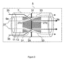
- FIG. 3 shows schematic representation of another embodiment of the image bearing roller 5.
- the imaging member consists of an outer tube 7, two inner tubes 9a and 9b and the central axis (not shown).
- the tubes define an inter tubular space 11 and an intra tubular space 13.
- the blocking member 27 is constituted of two disks 27c and 27d that are operatively engaged with the inner tubes 9a and 9b.
- the two discs are connected via the gasket 29.
- the gasket extends to the wall of the outer tube, dividing the inter tubular space in two parts. Flows of air 35 and 37 are transported through the roller from the left to the right.
- the inter tubular space 11 and the intra tubular space 13 are divided in a first part upstream of the blocking element and a second part downstream of the blocking element.
- the ducts 31 in the blocking element guide the flow of air 35 from the upstream part of the inter tubular space to the downstream part of the intra tubular space.
- the ducts 33 guide the air flow 37 from the upstream part of the intra tubular space to the downstream part of the inter tubular space. In this manner air flow 35 cools the first part of the roller surface and the air flow 37 cools the second part of the roller surface.
- the duct pair 31-33 forms a distorted double helix.
- Figure 4 shows a graph of the heat flow from the surface of the imaging roller to the air flow that passes though the roller as a function of the axial position of the roller.
- Trace 40 corresponds to the situation wherein the roller contains only an outer tube and an inner tube, without an blocking element and without any ducts.
- the heat flow from the imaging roller surface to the air flow steadily decreases when progressing along the longitudinal axis of the roller. This is due to the fact that the temperature of the air flow increases when passing through the roller. This results in a decrease of the temperature difference between the surface of the imaging roller and the air flow which results in a decreased heat flow.
- the heat flow in a steady state condition is viz. proportional to the temperature difference between the two bodies.
- the diminishing heat flow in the course of the roller results in a temperature gradient along the axis of the roller.
- Trace 42 corresponds to the situation wherein the roller comprises an outer tube and an inner tube with an blocking element with concomitant ducts.
- the trace 42 consists of a first part 42a and a second part 42c which are divided by a dip 42b.
- the dip 42b is caused by the presence of the blocking element. Where the blocking element contacts the inner surface of the outer tube, there is no air flow to carry away the heat from the surface of the roller.
- Trace 42a shows a decrease of the heat flow when progressing along the axis of the roller. This is due to the increasing temperature of the air flow in the inter tubular space by the uptake of heat from the roller surface.
Landscapes
- Physics & Mathematics (AREA)
- General Physics & Mathematics (AREA)
- Environmental Sciences (AREA)
- Biodiversity & Conservation Biology (AREA)
- Ecology (AREA)
- Environmental & Geological Engineering (AREA)
- Life Sciences & Earth Sciences (AREA)
- Atmospheric Sciences (AREA)
- Engineering & Computer Science (AREA)
- Control Or Security For Electrophotography (AREA)
- Electrophotography Configuration And Component (AREA)
- Rolls And Other Rotary Bodies (AREA)
- Fixing For Electrophotography (AREA)
Abstract
Description
- The invention pertains to a roller for a printer comprising an outer tube and positioned therein at least one inner tube, the outer tube extending in an axial direction from a first end to a second end and the inner tube extending substantially parallel to the outer tube, defining an inter tubular space between the outer and the inner tube and an intra tubular space within the inner tube.
The invention also pertains to a method of cooling the surface of such a roller.
Such rollers are commonly applied in e.g. electrophotographic printers. Rollers of this type are e.g. used as image bearing rollers or as cooling rollers. These are rollers that absorb heat in their operation and that require cooling of their surface. The cooling is usually done by blowing or sucking air through the interior of the roller with a fan.
Image bearing rollers are e.g. rollers that are covered with a photoconductive layer or with an electrode pattern. This enables the formation of an electrostatic image on the surface of the image bearing roller. In a subsequent step a layer of toner particles is developed onto the electrostatic image on the image bearing roller. This toner image is subsequently transferred to the receiving substrate and fused with the receiving substrate.
During the operation the surface temperature of the image bearing roller tends to increase. If the surface temperature rises too high, the toner particles will fuse and stick to the surface of the image bearing roller resulting in print artefacts. Therefore, the surface of the image bearing roller requires cooling by e.g. blowing air through the roller. Rollers according to the preamble are also used to as cooling rollers. When such a roller is rotably contacted with a substrate it will drain heat from that substrate thus cooling the substrate. The heat taken up by the cooling roller is then discharged with the air flow that passes through the roller. Optionally, it is also possible to discharge the heat with a flow of a liquid cooling agent that runs through the roller.
The disadvantage of the roller as described in the preamble is that a temperature gradient is formed in an axial direction along the surface. This is because the cold air that is blown into the inter tubular space of the roller immediately exchanges heat with the surface of the roller. Thus when progressing through the roller the air flow temperature increases. This reduces the temperature difference between the air flow and the surface of the roller. This subsequently leads to a reduced cooling capacity of the air flow near the end of the roller which results in a temperature gradient over the roller. Because of this temperature gradient the air flow must be sufficiently high in order to reach a specified temperature at the end to the roller. This leads to a relatively inefficient cooling system. - The object of the present invention is to provide a roller that has an improved cooling efficiency by reducing the temperature gradient over the roller.
- To this end a roller according to the preamble has been devised characterised in that the roller comprises a blocking element (27) dividing the inter tubular space and the intra tubular space in a first part extending substantially from the first end to the blocking element and a second part extending substantially from the blocking element to the second end and a first and a second duct (31, 33) connecting the first and second part of the inter tubular space with the second respectively the first part of the intra tubular space via the blocking element.
- The blocking element can be a disk like object that fits into the outer tube and extends though the inner tube, dividing both the intra tubular space and the inter tubular space into a first and a second part. The blocking element can entirely or partially block the flow through the roller and can be e.g. an injection moulded plastic object.
The outer tube can comprise lamellae that extend from the inner surface into the inter tubular space and stretch out along the longitudinal axis of the roller. These lamellae increase the inner surface area of the outer tube, which increases the effective contact area with the flow and thus increases the heat exchange capacity. The blocking element is configured such that it fits in the outer tube and has radial cuts from the outside inwards that allow the lamellae to pass through the blocking element. The size of these radial cuts can be adapted to control the fraction of the flow that is blocked and the fraction that is allowed to continue its path through the inter tubular space. - In order to allow the air flow to pass through the roller a first and a second duct are present extending through the blocking element and connecting the inter tubular space with the intra tubular space. This allows air that is blown into any of the first and the second part of inter tubular space to pass through the duct and to exit the roller via any of the first and the second part of the intra tubular space. Alternatively, air that is blown into the any of the first and the second part of the intra tubular space can exit the roller through any of the first and the second part of the inter tubular space.
For example air can be blown simultaneously into the first and the second part of the inter tubular space from both directions, using two fan units. The flow that is blown into the first part of the inter tubular space can exit the roller via the first part of the intra tubular space. The air flow that is simultaneously blown into the second part of the inter tubular space can exit the roller via the second part of the intra tubular space. - Preferably the blocking element is positioned at a central position along the axis of the roller. In this way the air that is blown through the first part of the inter tubular space and that cools the surface of the roller, cools only half of the roller surface. The surface temperature gradient over the first part of the roller is the same as in the absence of the blocking element. However in the absence of an blocking element the second part of roller surface will experience approximately the same gradient in surface temperature as in the first part resulting in a cumulative gradient in surface temperature over the entire roller surface of approximately two times the temperature gradient over the first part. In the embodiment incorporating the blocking element, every stream of the air is allowed to cool only half of the roller surface. Therefore, the gradient in surface temperature over the entire roller surface is not cumulative, but rather the first part and the second part of the surface independently experience the same gradient in surface temperature. The extreme temperature differences over the roller surface are thus reduced by approximately a factor of two, with respect to the situation without the blocking element.
- In a further embodiment the first and the second duct each connect one of the first and the second part of the inter tubular space with the opposing first or second part of the intra tubular space. This allows air to be blown through the roller from one direction. Air that is e.g. blown into the first part of the inter tubular space serves to cool the first part of the roller surface and exits the roller via the second part of the intra tubular space, where it does not cool the surface of the roller. Air that is simultaneously blown into the first part of the intra tubular space, where it does not cool the surface of the roller, passes through the second duct and exits the roller via the second part of the inter tubular space where it cools the surface of the roller.
- The flow rate through the roller can be optimised by choosing a high number of ducts and a large diameter of the ducts. It is also preferred to keep the curvature of the ducts as low as possible to obtain the lowest friction of the air flow with the duct walls.
It has been observed that for a given air pressure generated by the fan, a higher air flow through the inter tubular space can be realised with this roller system compared to the roller without the blocking element. The present roller system thus also has an improved cooling capacity with respect to the situation without blocking element. - In another embodiment the first duct and the second duct are arranged to form a double helix. This means that the entrance of e.g. the first duct on the first side of the inter tubular space lies radially above the entrance of the second duct on the same side of the intra tubular space. The exit of the first duct on the second side of the intra tubular space then lies radially underneath the exit of the second duct on the second side of the inter tubular space. The two ducts thus form a twisted pair, also called double helix, with a half pitch. In the middle of the blocking element the two ducts are tangentially juxtaposed. To obtain the maximal air flow through the roller, a plurality of duct pairs can be used.
- In yet another embodiment the blocking element is not longer than 40 mm in the axial direction. Because at the site of the blocking element there is no air flow for cooling the roller surface, the roller surface temperature can become relatively high on that location. Therefore it is favourable to keep the axial dimension of the blocking element as low as possible. But the narrower the blocking element, the stronger the curvature of the ducts, which results in an increased friction of the air flow with the duct walls which hampers the air flow through the blocking element. The axial dimension of the blocking element is therefore a trade-off between realising a sufficiently high air flow through the roller and minimising the jump in surface temperature of the roller surface due to the presence of the blocking element.
- In yet another embodiment the blocking element is constituted of two parts joined by a gasket. The blocking element can e.g. consist of two discs that entierly or partially divide the inter and intra tubular space, and which are joined by a gasket. The ducts that pass through the blocking element are thus segmented into a first and a second part. Every individual disk contains a quarter of a pitch of the duct pairs. Having a blocking element that consists of two separate discs has the advantage that the separate disks are easier to manufacture by e.g. injection moulding. The gasket can be made from e.g. a metal, a rubber or a plastic sheet and contains holes to connect the corresponding ducts from the first and the second disk constituting the blocking element.
The two disks constituting the blocking element can also be of approximately the size of the inner tube, and thus only divide the intra tubular space. The gasket can then extend into the inter tubular space to divide the inter tubular space. This embodiment has the advantage that the contact area of the gasket with the outer tube is only very narrow. Therefore the surface area of the roller that is not cooled by the air flow is almost negligible and there is hardly any jump in surface temperature of the roller. - The invention also pertains to a method of cooling the surface of a roller for a printer as described above, the method comprising transporting air from the first end of the roller to the second end of the roller and leading air that moves through the first part of the inter tubular space into the second part of the intra tubular space via the first duct and leading air that moves through the first part of the intra tubular space into the second part of the inter tubular space by way of the second duct in the blocking element. An air flow can e.g. be blown or sucked though the roller with a fan.
- Some of the embodiments will now be explained with reference to the figures given below.
- Figure 1 is a schematic representation of a printer comprising an image bearing roller according to the present invention.
- Figure 2 is a schematic representation of an embodiment of a roller according to the present invention.
- Figure 3 is a schematic representation of another embodiment of a roller according to the present invention.
- Figure 4 is a graph showing the heat transfer from the roller surface to the air flow as a function of the axial position of the roller.
- Figure 1 shows a schematic drawing of an
electrophotographic printer 1. The operation of an electrophotographic printer is known from the prior art. The heart of theprinter 1 is the print engine 3. The print engine 3 comprises animage bearing roller 5. Theimage bearing roller 5 comprises anouter tube 7 and an inner tube 9. On the surface of theimage bearing roller 5 is applied a photoconductive layer.(not shown) which is an insulator in the dark and a conductor when exposed to light. Initially, the photoconductive layer is given a total positive charge by thecharge corona wire 11, a wire with an electrical current running through it. As the drum revolves, the printer shines atiny laser beam 13 across the surface to discharge certain points, by reflecting the laser beam on a movablepolygonal mirror 15. In this way, the laser "draws" the letters and images to be printed as a pattern of electrical charges i.e. an electrostatic image. After the pattern is set, thetoner supply roller 17 coats the photoconductive layer with positively charged toner i.e. a fine, black powder. Since it has a positive charge, the toner clings to the negative discharged areas of the photoconductive layer, but not to the positively charged "background". With the powder pattern affixed, theimage bearing roller 5 rolls over a sheet of paper that has been separated from thepaper stack 19 and which is moving along abelt 21 below. Before the paper rolls under the image bearing roller, it is given a negative charge by a transfer corona wire (not shown). This charge is stronger than the negative charge of the electrostatic image, so the paper can pull the toner powder away. Since it is moving at the same speed as theimage bearing roller 5, the paper picks up the image pattern exactly. Finally, the printer passes the paper through thefuser 23, i.e. a pair of heated rollers. As the paper passes through these rollers, the loose toner powder melts, fusing with the fibres in the paper. The fuser rolls the paper to the output tray (not shown). The surface temperature of theimage bearing roller 5 tends to increase during operation. The surface temperature may however not exceed the melting temperature of the toner powder because then toner powder will fuse with the photoconductive layer on the image bearing roller resulting in print artefacts. Therefore, a fan-unit (not shown) blows air through the inner tube 9 and theouter tube 7 in order to cool the surface of the image bearing member. - Figure 2 shows a schematic representation of the
image bearing roller 5. The imaging member consists of anouter tube 7, twoinner tubes tubular space 11 and an intratubular space 13. The blockingmember 27 is a one-piece disk that fits tightly into the outer tube. The blocking element has two disk-like protrusions inner tubes air tubular space 11 and the intratubular space 13 are divided in a first part upstream of the blocking element and a second part downstream of the blocking element. Theducts 31 in the blocking element guide the flow ofair 35 from the upstream part of the intertubular space 11 to the downstream part of the intratubular space 13. Theducts 33 guide theair flow 37 from the upstream part of the intra tubular space to the downstream part of the inter tubular space. In thismanner air flow 35 cools the first part of the roller surface and theair flow 37 cools the second part of the roller surface. The duct pair 31-33 forms a double helix with a half pitch. The entrances of both ducts are radially aligned with the entrance ofduct 31 lying further away from the central axis than the entrance ofduct 33. The exits of both ducts are also radially aligned with the exit ofduct 33 lying further away from the central axis than the exit ofduct 31.
Figure 3 shows schematic representation of another embodiment of theimage bearing roller 5. The imaging member consists of anouter tube 7, twoinner tubes tubular space 11 and an intratubular space 13. The blockingmember 27 is constituted of twodisks 27c and 27d that are operatively engaged with theinner tubes gasket 29. The gasket extends to the wall of the outer tube, dividing the inter tubular space in two parts. Flows ofair tubular space 11 and the intratubular space 13 are divided in a first part upstream of the blocking element and a second part downstream of the blocking element. Theducts 31 in the blocking element guide the flow ofair 35 from the upstream part of the inter tubular space to the downstream part of the intra tubular space. Theducts 33 guide theair flow 37 from the upstream part of the intra tubular space to the downstream part of the inter tubular space. In thismanner air flow 35 cools the first part of the roller surface and theair flow 37 cools the second part of the roller surface. The duct pair 31-33 forms a distorted double helix. - Figure 4 shows a graph of the heat flow from the surface of the imaging roller to the air flow that passes though the roller as a function of the axial position of the roller.
Trace 40 corresponds to the situation wherein the roller contains only an outer tube and an inner tube, without an blocking element and without any ducts. The heat flow from the imaging roller surface to the air flow steadily decreases when progressing along the longitudinal axis of the roller. This is due to the fact that the temperature of the air flow increases when passing through the roller. This results in a decrease of the temperature difference between the surface of the imaging roller and the air flow which results in a decreased heat flow. The heat flow in a steady state condition is viz. proportional to the temperature difference between the two bodies. The diminishing heat flow in the course of the roller results in a temperature gradient along the axis of the roller. - Trace 42 corresponds to the situation wherein the roller comprises an outer tube and an inner tube with an blocking element with concomitant ducts. The trace 42 consists of a
first part 42a and asecond part 42c which are divided by adip 42b. Thedip 42b is caused by the presence of the blocking element. Where the blocking element contacts the inner surface of the outer tube, there is no air flow to carry away the heat from the surface of the roller.Trace 42a shows a decrease of the heat flow when progressing along the axis of the roller. This is due to the increasing temperature of the air flow in the inter tubular space by the uptake of heat from the roller surface. When the air flow reaches the blocking element the air flow goes through the ducts and into the intra tubular space on the other side of the blocking element and then exits the roller. Simultaneously, the air flow that is blown into the first part of the intra tubular space reaches the blocking element. This air flow has maintained its initial temperature because it has not exchanged heat with the surface of the roller. This air flow passes through the ducts into the second part of the inter tubular space. Now the air flow comes into heat exchanging contact with the surface of the roller. The heat flow from the surface of the roller to the air flow immediately reaches its maximum value, and then progressively decreases towards the end of the roller. The result is that the absolute differences in heat flow in trace 42 are significantly reduced with respect to trace 40.Dip 42b must be kept as narrow as possible in order to avoid overheating of the corresponding part of the roller surface. This is realised by using the embodiment of Figure 3.
Claims (6)
- A roller (5) for a printer (1) comprising an outer tube (7) and positioned therein at least one inner tube (9), the outer tube extending in an axial direction from a first end to a second end and the inner tube extending substantially parallel to the outer tube, defining an inter tubular space (11) between the outer and the inner tube and an intra tubular space (13) within the inner tube, characterised in that the roller comprises a blocking element (27) dividing the inter tubular space and the intra tubular space in a first part extending substantially from the first end to the blocking element and a second part extending substantially from the blocking element to the second end and a first and a second duct (31, 33) connecting the first and second part of the inter tubular space with the second respectively the first part of the intra tubular space via the blocking element.
- A roller (5) for a printer (1) according to claim 2 characterised in that the first duct and the second duct are arranged to form a double helix.
- A roller (5) for a printer (1) according to any of the preceding claims characterised in that the blocking element is not longer than 40 mm in the axial direction.
- A roller (5) for a printer (1) according to any of the preceding claims characterised in that the blocking element (27) is constituted of two parts joined by a gasket (29).
- Printing system, comprising a roller (5) according to any one of preceding claims.
- A method of cooling the surface of a roller (5) for a printing system according to claim 5, the method comprising transporting air from the first end of the roller to the second end of the roller and leading air that moves through the first part of the inter tubular space (11) into the second part of the intra tubular space (13) via the first duct (31) and leading air that moves through the first part of the intra tubular space (13) into the second part of the inter tubular space (33) by way of the second duct in the blocking element (27).
Priority Applications (1)
| Application Number | Priority Date | Filing Date | Title |
|---|---|---|---|
| EP20070110015 EP1870781B1 (en) | 2006-06-21 | 2007-06-11 | A roller for a printer and a method of cooling the roller surface |
Applications Claiming Priority (2)
| Application Number | Priority Date | Filing Date | Title |
|---|---|---|---|
| EP06115805 | 2006-06-21 | ||
| EP20070110015 EP1870781B1 (en) | 2006-06-21 | 2007-06-11 | A roller for a printer and a method of cooling the roller surface |
Publications (2)
| Publication Number | Publication Date |
|---|---|
| EP1870781A1 true EP1870781A1 (en) | 2007-12-26 |
| EP1870781B1 EP1870781B1 (en) | 2013-08-14 |
Family
ID=38719746
Family Applications (1)
| Application Number | Title | Priority Date | Filing Date |
|---|---|---|---|
| EP20070110015 Not-in-force EP1870781B1 (en) | 2006-06-21 | 2007-06-11 | A roller for a printer and a method of cooling the roller surface |
Country Status (1)
| Country | Link |
|---|---|
| EP (1) | EP1870781B1 (en) |
Citations (5)
| Publication number | Priority date | Publication date | Assignee | Title |
|---|---|---|---|---|
| GB1000235A (en) * | 1963-12-16 | 1965-08-04 | Marshall And Williams Corp | Heat exchange roll |
| US3752227A (en) * | 1972-01-06 | 1973-08-14 | Gen Tire & Rubber Co | Embossing roll with integral cooling means |
| US4607936A (en) * | 1983-09-30 | 1986-08-26 | Mita Industrial Co., Ltd. | Electrophotographic apparatus comprising photosensitive layer of amorphous silicon type photoconductor |
| JPH0299253A (en) * | 1988-09-30 | 1990-04-11 | Kubota Ltd | Assembling type roll for continuous casting slab |
| US5788382A (en) * | 1997-08-28 | 1998-08-04 | Output Technology, Inc. | Imaging drum |
-
2007
- 2007-06-11 EP EP20070110015 patent/EP1870781B1/en not_active Not-in-force
Patent Citations (5)
| Publication number | Priority date | Publication date | Assignee | Title |
|---|---|---|---|---|
| GB1000235A (en) * | 1963-12-16 | 1965-08-04 | Marshall And Williams Corp | Heat exchange roll |
| US3752227A (en) * | 1972-01-06 | 1973-08-14 | Gen Tire & Rubber Co | Embossing roll with integral cooling means |
| US4607936A (en) * | 1983-09-30 | 1986-08-26 | Mita Industrial Co., Ltd. | Electrophotographic apparatus comprising photosensitive layer of amorphous silicon type photoconductor |
| JPH0299253A (en) * | 1988-09-30 | 1990-04-11 | Kubota Ltd | Assembling type roll for continuous casting slab |
| US5788382A (en) * | 1997-08-28 | 1998-08-04 | Output Technology, Inc. | Imaging drum |
Non-Patent Citations (1)
| Title |
|---|
| "COOLING DRUM", RESEARCH DISCLOSURE, MASON PUBLICATIONS, HAMPSHIRE, GB, no. 316, 1 August 1990 (1990-08-01), pages 600, XP000140910, ISSN: 0374-4353 * |
Also Published As
| Publication number | Publication date |
|---|---|
| EP1870781B1 (en) | 2013-08-14 |
Similar Documents
| Publication | Publication Date | Title |
|---|---|---|
| JP5768507B2 (en) | Fixing apparatus and image forming apparatus | |
| US7890014B2 (en) | Image forming apparatus with air blowing device for cooling rotary member | |
| US8903265B2 (en) | Fixing apparatus | |
| US9411275B2 (en) | Image forming apparatus having partition configured to separate air flow and sheet feeding paths | |
| JP4814927B2 (en) | Sheet deposition apparatus and image forming apparatus | |
| US7933530B2 (en) | Fuser assembly fan control | |
| CN108475035A (en) | Imaging device | |
| US7725055B2 (en) | Roller for a printer and a method of cooling the roller surface | |
| US10185263B2 (en) | Image forming apparatus having a fixing portion and at least one opening for fluid communication between an inside and an outside of the fixing portion | |
| EP1770451A2 (en) | Image forming apparatus | |
| US9002231B2 (en) | Image forming apparatus with guide member to guide air | |
| EP1870781B1 (en) | A roller for a printer and a method of cooling the roller surface | |
| US11567437B2 (en) | Photo finisher with duct apart from belt | |
| JP3780786B2 (en) | Fixing device | |
| US12372905B2 (en) | Image forming apparatus | |
| JP3902462B2 (en) | Fixing device | |
| US20080193174A1 (en) | Convective hot air impingement device with localized return paths | |
| CN106249571B (en) | Image forming apparatus with a toner supply device | |
| US11221586B2 (en) | Image forming apparatus | |
| JPH11305637A (en) | Image forming device | |
| US11440764B2 (en) | Sheet discharge apparatus and image forming apparatus | |
| US11803138B2 (en) | Fixing apparatus with blower member for multi-directional cooling | |
| JP7676228B2 (en) | Sheet ejection device and image forming apparatus | |
| CN117130250A (en) | Image forming apparatus having a plurality of image forming units | |
| JP4454404B2 (en) | Fixing apparatus, image forming apparatus, and toner fixing method |
Legal Events
| Date | Code | Title | Description |
|---|---|---|---|
| PUAI | Public reference made under article 153(3) epc to a published international application that has entered the european phase |
Free format text: ORIGINAL CODE: 0009012 |
|
| AK | Designated contracting states |
Kind code of ref document: A1 Designated state(s): AT BE BG CH CY CZ DE DK EE ES FI FR GB GR HU IE IS IT LI LT LU LV MC MT NL PL PT RO SE SI SK TR |
|
| AX | Request for extension of the european patent |
Extension state: AL BA HR MK YU |
|
| 17P | Request for examination filed |
Effective date: 20080626 |
|
| 17Q | First examination report despatched |
Effective date: 20080725 |
|
| AKX | Designation fees paid |
Designated state(s): AT BE BG CH CY CZ DE DK EE ES FI FR GB GR HU IE IS IT LI LT LU LV MC MT NL PL PT RO SE SI SK TR |
|
| GRAP | Despatch of communication of intention to grant a patent |
Free format text: ORIGINAL CODE: EPIDOSNIGR1 |
|
| GRAS | Grant fee paid |
Free format text: ORIGINAL CODE: EPIDOSNIGR3 |
|
| GRAA | (expected) grant |
Free format text: ORIGINAL CODE: 0009210 |
|
| AK | Designated contracting states |
Kind code of ref document: B1 Designated state(s): AT BE BG CH CY CZ DE DK EE ES FI FR GB GR HU IE IS IT LI LT LU LV MC MT NL PL PT RO SE SI SK TR |
|
| REG | Reference to a national code |
Ref country code: GB Ref legal event code: FG4D |
|
| REG | Reference to a national code |
Ref country code: CH Ref legal event code: EP Ref country code: AT Ref legal event code: REF Ref document number: 627183 Country of ref document: AT Kind code of ref document: T Effective date: 20130815 |
|
| REG | Reference to a national code |
Ref country code: IE Ref legal event code: FG4D |
|
| REG | Reference to a national code |
Ref country code: DE Ref legal event code: R096 Ref document number: 602007032199 Country of ref document: DE Effective date: 20131010 |
|
| REG | Reference to a national code |
Ref country code: NL Ref legal event code: VDEP Effective date: 20130814 Ref country code: AT Ref legal event code: MK05 Ref document number: 627183 Country of ref document: AT Kind code of ref document: T Effective date: 20130814 |
|
| REG | Reference to a national code |
Ref country code: LT Ref legal event code: MG4D |
|
| PG25 | Lapsed in a contracting state [announced via postgrant information from national office to epo] |
Ref country code: LT Free format text: LAPSE BECAUSE OF FAILURE TO SUBMIT A TRANSLATION OF THE DESCRIPTION OR TO PAY THE FEE WITHIN THE PRESCRIBED TIME-LIMIT Effective date: 20130814 Ref country code: AT Free format text: LAPSE BECAUSE OF FAILURE TO SUBMIT A TRANSLATION OF THE DESCRIPTION OR TO PAY THE FEE WITHIN THE PRESCRIBED TIME-LIMIT Effective date: 20130814 Ref country code: PT Free format text: LAPSE BECAUSE OF FAILURE TO SUBMIT A TRANSLATION OF THE DESCRIPTION OR TO PAY THE FEE WITHIN THE PRESCRIBED TIME-LIMIT Effective date: 20131216 Ref country code: CY Free format text: LAPSE BECAUSE OF FAILURE TO SUBMIT A TRANSLATION OF THE DESCRIPTION OR TO PAY THE FEE WITHIN THE PRESCRIBED TIME-LIMIT Effective date: 20130703 Ref country code: IS Free format text: LAPSE BECAUSE OF FAILURE TO SUBMIT A TRANSLATION OF THE DESCRIPTION OR TO PAY THE FEE WITHIN THE PRESCRIBED TIME-LIMIT Effective date: 20131214 Ref country code: SE Free format text: LAPSE BECAUSE OF FAILURE TO SUBMIT A TRANSLATION OF THE DESCRIPTION OR TO PAY THE FEE WITHIN THE PRESCRIBED TIME-LIMIT Effective date: 20130814 |
|
| PG25 | Lapsed in a contracting state [announced via postgrant information from national office to epo] |
Ref country code: BE Free format text: LAPSE BECAUSE OF FAILURE TO SUBMIT A TRANSLATION OF THE DESCRIPTION OR TO PAY THE FEE WITHIN THE PRESCRIBED TIME-LIMIT Effective date: 20130814 Ref country code: ES Free format text: LAPSE BECAUSE OF FAILURE TO SUBMIT A TRANSLATION OF THE DESCRIPTION OR TO PAY THE FEE WITHIN THE PRESCRIBED TIME-LIMIT Effective date: 20130814 Ref country code: GR Free format text: LAPSE BECAUSE OF FAILURE TO SUBMIT A TRANSLATION OF THE DESCRIPTION OR TO PAY THE FEE WITHIN THE PRESCRIBED TIME-LIMIT Effective date: 20131115 Ref country code: LV Free format text: LAPSE BECAUSE OF FAILURE TO SUBMIT A TRANSLATION OF THE DESCRIPTION OR TO PAY THE FEE WITHIN THE PRESCRIBED TIME-LIMIT Effective date: 20130814 Ref country code: FI Free format text: LAPSE BECAUSE OF FAILURE TO SUBMIT A TRANSLATION OF THE DESCRIPTION OR TO PAY THE FEE WITHIN THE PRESCRIBED TIME-LIMIT Effective date: 20130814 Ref country code: SI Free format text: LAPSE BECAUSE OF FAILURE TO SUBMIT A TRANSLATION OF THE DESCRIPTION OR TO PAY THE FEE WITHIN THE PRESCRIBED TIME-LIMIT Effective date: 20130814 Ref country code: PL Free format text: LAPSE BECAUSE OF FAILURE TO SUBMIT A TRANSLATION OF THE DESCRIPTION OR TO PAY THE FEE WITHIN THE PRESCRIBED TIME-LIMIT Effective date: 20130814 |
|
| PG25 | Lapsed in a contracting state [announced via postgrant information from national office to epo] |
Ref country code: CY Free format text: LAPSE BECAUSE OF FAILURE TO SUBMIT A TRANSLATION OF THE DESCRIPTION OR TO PAY THE FEE WITHIN THE PRESCRIBED TIME-LIMIT Effective date: 20130814 |
|
| PG25 | Lapsed in a contracting state [announced via postgrant information from national office to epo] |
Ref country code: CZ Free format text: LAPSE BECAUSE OF FAILURE TO SUBMIT A TRANSLATION OF THE DESCRIPTION OR TO PAY THE FEE WITHIN THE PRESCRIBED TIME-LIMIT Effective date: 20130814 Ref country code: RO Free format text: LAPSE BECAUSE OF FAILURE TO SUBMIT A TRANSLATION OF THE DESCRIPTION OR TO PAY THE FEE WITHIN THE PRESCRIBED TIME-LIMIT Effective date: 20130814 Ref country code: DK Free format text: LAPSE BECAUSE OF FAILURE TO SUBMIT A TRANSLATION OF THE DESCRIPTION OR TO PAY THE FEE WITHIN THE PRESCRIBED TIME-LIMIT Effective date: 20130814 Ref country code: NL Free format text: LAPSE BECAUSE OF FAILURE TO SUBMIT A TRANSLATION OF THE DESCRIPTION OR TO PAY THE FEE WITHIN THE PRESCRIBED TIME-LIMIT Effective date: 20130814 Ref country code: SK Free format text: LAPSE BECAUSE OF FAILURE TO SUBMIT A TRANSLATION OF THE DESCRIPTION OR TO PAY THE FEE WITHIN THE PRESCRIBED TIME-LIMIT Effective date: 20130814 Ref country code: EE Free format text: LAPSE BECAUSE OF FAILURE TO SUBMIT A TRANSLATION OF THE DESCRIPTION OR TO PAY THE FEE WITHIN THE PRESCRIBED TIME-LIMIT Effective date: 20130814 |
|
| PG25 | Lapsed in a contracting state [announced via postgrant information from national office to epo] |
Ref country code: IT Free format text: LAPSE BECAUSE OF FAILURE TO SUBMIT A TRANSLATION OF THE DESCRIPTION OR TO PAY THE FEE WITHIN THE PRESCRIBED TIME-LIMIT Effective date: 20130814 |
|
| PLBE | No opposition filed within time limit |
Free format text: ORIGINAL CODE: 0009261 |
|
| STAA | Information on the status of an ep patent application or granted ep patent |
Free format text: STATUS: NO OPPOSITION FILED WITHIN TIME LIMIT |
|
| 26N | No opposition filed |
Effective date: 20140515 |
|
| REG | Reference to a national code |
Ref country code: DE Ref legal event code: R097 Ref document number: 602007032199 Country of ref document: DE Effective date: 20140515 |
|
| PG25 | Lapsed in a contracting state [announced via postgrant information from national office to epo] |
Ref country code: LU Free format text: LAPSE BECAUSE OF FAILURE TO SUBMIT A TRANSLATION OF THE DESCRIPTION OR TO PAY THE FEE WITHIN THE PRESCRIBED TIME-LIMIT Effective date: 20140611 Ref country code: MC Free format text: LAPSE BECAUSE OF FAILURE TO SUBMIT A TRANSLATION OF THE DESCRIPTION OR TO PAY THE FEE WITHIN THE PRESCRIBED TIME-LIMIT Effective date: 20130814 |
|
| REG | Reference to a national code |
Ref country code: CH Ref legal event code: PL |
|
| REG | Reference to a national code |
Ref country code: IE Ref legal event code: MM4A |
|
| PG25 | Lapsed in a contracting state [announced via postgrant information from national office to epo] |
Ref country code: IE Free format text: LAPSE BECAUSE OF NON-PAYMENT OF DUE FEES Effective date: 20140611 Ref country code: CH Free format text: LAPSE BECAUSE OF NON-PAYMENT OF DUE FEES Effective date: 20140630 Ref country code: LI Free format text: LAPSE BECAUSE OF NON-PAYMENT OF DUE FEES Effective date: 20140630 |
|
| PG25 | Lapsed in a contracting state [announced via postgrant information from national office to epo] |
Ref country code: MT Free format text: LAPSE BECAUSE OF FAILURE TO SUBMIT A TRANSLATION OF THE DESCRIPTION OR TO PAY THE FEE WITHIN THE PRESCRIBED TIME-LIMIT Effective date: 20130814 |
|
| PG25 | Lapsed in a contracting state [announced via postgrant information from national office to epo] |
Ref country code: BG Free format text: LAPSE BECAUSE OF FAILURE TO SUBMIT A TRANSLATION OF THE DESCRIPTION OR TO PAY THE FEE WITHIN THE PRESCRIBED TIME-LIMIT Effective date: 20130814 |
|
| REG | Reference to a national code |
Ref country code: FR Ref legal event code: PLFP Year of fee payment: 10 |
|
| PG25 | Lapsed in a contracting state [announced via postgrant information from national office to epo] |
Ref country code: HU Free format text: LAPSE BECAUSE OF FAILURE TO SUBMIT A TRANSLATION OF THE DESCRIPTION OR TO PAY THE FEE WITHIN THE PRESCRIBED TIME-LIMIT; INVALID AB INITIO Effective date: 20070611 Ref country code: TR Free format text: LAPSE BECAUSE OF FAILURE TO SUBMIT A TRANSLATION OF THE DESCRIPTION OR TO PAY THE FEE WITHIN THE PRESCRIBED TIME-LIMIT Effective date: 20130814 |
|
| REG | Reference to a national code |
Ref country code: FR Ref legal event code: PLFP Year of fee payment: 11 |
|
| REG | Reference to a national code |
Ref country code: FR Ref legal event code: PLFP Year of fee payment: 12 |
|
| PGFP | Annual fee paid to national office [announced via postgrant information from national office to epo] |
Ref country code: GB Payment date: 20240619 Year of fee payment: 18 |
|
| PGFP | Annual fee paid to national office [announced via postgrant information from national office to epo] |
Ref country code: DE Payment date: 20240619 Year of fee payment: 18 |
|
| PGFP | Annual fee paid to national office [announced via postgrant information from national office to epo] |
Ref country code: FR Payment date: 20240628 Year of fee payment: 18 |
|
| REG | Reference to a national code |
Ref country code: DE Ref legal event code: R119 Ref document number: 602007032199 Country of ref document: DE |
|
| GBPC | Gb: european patent ceased through non-payment of renewal fee |
Effective date: 20250611 |
|
| PG25 | Lapsed in a contracting state [announced via postgrant information from national office to epo] |
Ref country code: GB Free format text: LAPSE BECAUSE OF NON-PAYMENT OF DUE FEES Effective date: 20250611 |
|
| PG25 | Lapsed in a contracting state [announced via postgrant information from national office to epo] |
Ref country code: DE Free format text: LAPSE BECAUSE OF NON-PAYMENT OF DUE FEES Effective date: 20260101 |
|
| PG25 | Lapsed in a contracting state [announced via postgrant information from national office to epo] |
Ref country code: FR Free format text: LAPSE BECAUSE OF NON-PAYMENT OF DUE FEES Effective date: 20250630 |