EP1870751A1 - Mount for positioning an optical element - Google Patents
Mount for positioning an optical element Download PDFInfo
- Publication number
- EP1870751A1 EP1870751A1 EP06076294A EP06076294A EP1870751A1 EP 1870751 A1 EP1870751 A1 EP 1870751A1 EP 06076294 A EP06076294 A EP 06076294A EP 06076294 A EP06076294 A EP 06076294A EP 1870751 A1 EP1870751 A1 EP 1870751A1
- Authority
- EP
- European Patent Office
- Prior art keywords
- respect
- main frame
- mount
- restrictive
- displacement
- Prior art date
- Legal status (The legal status is an assumption and is not a legal conclusion. Google has not performed a legal analysis and makes no representation as to the accuracy of the status listed.)
- Withdrawn
Links
- 230000003287 optical effect Effects 0.000 title claims abstract description 37
- 238000006073 displacement reaction Methods 0.000 claims abstract description 36
- 230000007246 mechanism Effects 0.000 description 3
- 238000003384 imaging method Methods 0.000 description 2
- 239000000463 material Substances 0.000 description 2
- 230000004048 modification Effects 0.000 description 2
- 238000012986 modification Methods 0.000 description 2
- 239000006094 Zerodur Substances 0.000 description 1
- XAGFODPZIPBFFR-UHFFFAOYSA-N aluminium Chemical compound [Al] XAGFODPZIPBFFR-UHFFFAOYSA-N 0.000 description 1
- 229910052782 aluminium Inorganic materials 0.000 description 1
- 239000004411 aluminium Substances 0.000 description 1
- 230000008901 benefit Effects 0.000 description 1
- 230000015572 biosynthetic process Effects 0.000 description 1
- 230000008878 coupling Effects 0.000 description 1
- 238000010168 coupling process Methods 0.000 description 1
- 238000005859 coupling reaction Methods 0.000 description 1
- 239000002241 glass-ceramic Substances 0.000 description 1
- 125000006850 spacer group Chemical group 0.000 description 1
- 230000007480 spreading Effects 0.000 description 1
- 230000003068 static effect Effects 0.000 description 1
Images



Classifications
-
- G—PHYSICS
- G02—OPTICS
- G02B—OPTICAL ELEMENTS, SYSTEMS OR APPARATUS
- G02B7/00—Mountings, adjusting means, or light-tight connections, for optical elements
- G02B7/18—Mountings, adjusting means, or light-tight connections, for optical elements for prisms; for mirrors
- G02B7/182—Mountings, adjusting means, or light-tight connections, for optical elements for prisms; for mirrors for mirrors
-
- G—PHYSICS
- G02—OPTICS
- G02B—OPTICAL ELEMENTS, SYSTEMS OR APPARATUS
- G02B26/00—Optical devices or arrangements for the control of light using movable or deformable optical elements
- G02B26/08—Optical devices or arrangements for the control of light using movable or deformable optical elements for controlling the direction of light
- G02B26/0816—Optical devices or arrangements for the control of light using movable or deformable optical elements for controlling the direction of light by means of one or more reflecting elements
Definitions
- the invention relates to a mount for positioning an optical element, having one or more optically active surfaces, such as a mirror segment having a reflective surface.
- the invention relates to an optical system comprising a main frame and such a mount.
- Such mounts are often used in telescopes for positioning mirror segments having a reflective surface.
- the mirror segments are positioned to form a mirror which also has to be positioned with respect to a main frame comprised in the telescope.
- Accurate positioning of the mirror segments in a translational direction perpendicular to the reflective surface and a rotational positioning of the mirror segments with respect to an axis parallel to the reflective surface are important to the imaging quality of the mirror.
- Good support of the mirror segments is also desirable in the other directions in order to prevent vibrations in these directions to interfere with the proper functioning of the optical system as a whole.
- Good support of the mirror segments is further desirable for maintaining the mirror shape and preventing undesired stress in the mirror created by the mirror segment's pressing against each other.
- the mount comprises a main frame and one or more strut frames, each of the strut frames comprising a plurality of struts, each of the struts being configured to support the optical element at a support contact and to restrict displacement of the support contact perpendicular to the optically active surface.
- the mount may comprise one or more actuators for actuating the strut frames in a longitudinal direction of the struts with respect to the main frame.
- strut frames are provided, since this could allow for translational positioning of the optical element perpendicular to the optically active surface, as well as the rotational positioning of the mirror segments with respect to an axis parallel to the reflective surface.
- the struts restrict any translational displacement of the mirror segment and allow for translation of the mirror segment parallel to the reflective surface and any rotational displacement of the mirror segment with respect to an axis parallel to the reflective surface. Also, such use of struts allows the edges of the mirror segment free of any support in order to allow for the formation of mirrors from a plurality of mirror segments.
- a mount having a support mechanism centrally mounted on a mirror segment, the mount further comprising several struts for positioning the mirror segment in a longitudinal direction of the struts.
- the support mechanism restricts displacements in any direction perpendicular thereto.
- a disadvantage of such a known mount is that the support mechanism requires separate adjustment of the mirror segment. Such adjustment is effected by a separate actuator.
- An object of the present invention is to provide the possibility to overcome the mentioned disadvantage.
- the mount comprises at least one restrictive element, wherein the at least one restrictive element is mechanically coupled to a said strut near the support contact and wherein each of the at least one restrictive element is arranged to restrict displacement of the optical element with respect to the main frame in a direction substantially parallel to the optically active surface and to allow for displacement of the optical element with respect to the main frame in another direction substantially parallel to the optically active surface.
- the optical element may at least partially be relieved of the internal stress which would occur if the optical element were restricted in all directions parallel to the optically active surface.
- the restrictive element since the mechanical coupling between the at least one restrictive element and the strut is near the support contact, the restrictive element does not require an separate adjustment to allow it to adjust to any displacements of the support contact.
- the mount comprises several such restrictive elements, each restrictive element being mechanically coupled to a different said strut. If several restrictive elements are used, any internal stress due to support of the restrictive elements present in the optical element is spread over several locations, thereby reducing the overall influence of the stress on the properties of the optically active surface. Also, since the support is spread over several struts, small support contacts may be allowed for, which reduces stress that may occur at a contact surface of the support contact due to temperature variations.
- a first said restrictive element may be arranged to restrict displacement of the optical element with respect to the main frame in at least a first said direction and a second said restrictive element may be arranged to restrict displacement of the optical element with respect to the main frame in at least a second said direction, the first direction and the second direction differing from each other.
- a further modification of this embodiment is possible, wherein a third said restrictive element is provided, which is arranged to restrict displacement of the optical element with respect to the main frame in at least a third said direction which differs from the first and second directions, wherein the displacement allowed by the first, second and third restrictive elements at least nearly define a central point, the first, second and third directions being tangential directions with respect to the central point.
- An advantage of such a modification may be that the mirror segment is maintained centered, while thermal expansion is being allowed. Furthermore, owing to the restriction in tangential directions, rotation of the mirror segment around the central point is well-restricted.
- the mount is provided, wherein at least one said restrictive element is arranged to allow displacement of the optical element with respect to the main frame in any direction substantially perpendicular to the first direction, thereby including a direction substantially perpendicular to the optically active surface.
- the resilient element may comprise one or more oblong legs mechanically coupled to the support contact for allowing displacement of the contact with respect to the main frame in any direction substantially perpendicular to the first direction.
- Such geometry suitably allows for translation in two perpendicular directions, as well as rotation in two perpendicular directions.
- the mount may comprise one or more strut frames, each of the strut frames being provided with at least one said strut, wherein some of the strut frames are provided with at least one subframe on which two or more struts of the plurality of struts are located.
- the strut frames provided with the at least one subframe preferably comprise a strut for supporting each of the at least one subframe.
- Figure 1 shows a mirror 1 having mirror segments 2 which can be positioned using a mount 4 (see Figure 2) according to the present invention.
- Each of the mirror segments 2 have a reflective surface 6.
- it is desirable that the mirror segments 2 are positioned in such a manner that the reflective surfaces 6 of each of the segments are positioned such that they form an at least nearly continuous reflective plane 8.
- An example of such mirror segments 2 are segments manufactured from Zerodur®, which is a glass ceramic.
- the segments 2 may be polished and coated with a layer of reflective aluminium.
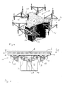
- FIGs 2, 3 and 4 illustrate in perspective view an embodiment of the mount 4.
- the mount 4 comprises a main frame 10 having an actuator frame 12 and a support plate 14, in which material has been cut out in order to form restrictive elements 16.
- the material has been cut out at two different locations 18 and 20 in order to form one of the restrictive elements 16.
- Each of the restrictive elements 16 comprises substantially parallel legs 21 mechanically coupled to the support contact for allowing displacement of the contact with respect to the main frame in any direction substantially perpendicular to the longitudinal direction of the legs 21 and restricting displacement of the mirror in a direction parallel to the longitudinal direction of the legs 21.
- FIGs 6C and 6D it can be seen that the restrictive elements 16 allow for displacement in a direction parallel to the support plate.
- each of the restrictive elements 16 allow for displacement of the mirror segment with respect to the main frame 10 in different radial directions and restrict displacement of the mirror segment with respect to the main frame 10 in different tangential directions. Furthermore, a person skilled in the art will recognise from Figure 2 that rotation with respect to an axis P and an axis Q are also possible.
- the support plate 14 comprises mounting hubs 22, a spacer 24 having, in this example, radially extending portions 24' and a circumferentially extending portion 24" (see Figure 3).
- the hubs 22 are integrally comprised the radially extending portion 24' and are configured to be mounted on the actuator frame 12 of the main frame 10.
- the mount 4 comprises connection pads 26 which, in use, form support contacts between the mount and the mirror segment 2 and the mount 4.
- the mount 4 further comprises three strut frames 28 (see Figure 4).
- the coefficient of thermal expansion of the connection pads 26 preferably match the coefficient of thermal expansion of the mirror to be used.
- Each of the strut frames 28 is mechanically coupled to two subframes 30 through respective subframe struts 31.
- Each of the subframes 30 has three struts 32.
- the actuator frame 12 is provided with actuators 34 for positioning the respective strut frame 28, its two subframes 30 and the struts 32 in a longitudinal direction L of the struts 32.
- the actuator is, in this example, formed by a cantilever 34 mounted on the actuator frame 12 using a hinge (the hinge not being shown in the drawings).
- the struts 32 are located to support the mirror segment 2 at the connection pads 26.
- the struts 32 are connected to the connection pads 26.
- the mount works as follows. For positioning the mirror segment 2 in a translational direction T perpendicular to the reflective surface 6 of the mirror segment, each of the actuators 34 translates the strut frames over a distance which is equal for all the actuators 34. As a consequence, the mirror segment 2 is positioned mainly in a translational manner, since the struts 32 and therefore the connections pads 26 remain mainly static with respect to each other.
- each of the actuators 34 For positioning the mirror segment 2 in a rotational direction R with respect to an axis A parallel to the reflective surface 6, each of the actuators 34 translates the strut frames 28 over a distance which is different for the actuators 34. Since the actuators 34 as well as the connection pads 26 are translated with respect to each other, the mirror segment 2 and the reflective surface 6 rotate with respect to an axis parallel to the reflective surface 6. Thus, the positioning of the mirror segment 2 in the directions mentioned above can be effected.
- the mirror segments 2 are also supported in directions which, in optical sense, are of less relevance. Such directions are the translational directions parallel to the reflective surface 6 of the mirror segment 2 and the rotational direction with respect to an axis perpendicular to the reflective surface 6 of the mirror segment 2.
- the mirror segment 2 is supported by the restrictive elements 16. By supporting the mirror segment 2 at different locations, any internal stress present in the mirror segment is limited per restrictive element 16.
- the displacement allowed for by the restrictive elements 16 in this example define a central point C.
- Each of the restrictive elements is arranged to restrict displacement of the optical element with respect to the central point C in a tangential direction of the mirror segment 2. Furthermore, the amount of internal stress caused by a difference in thermal expansion coefficient of the mirror segment 2 and the support plate 14 is reduced by the fact that each of the restrictive elements 16 allow for displacement in a radial direction with respect to the central point. The mirror segment 2 is therefore allowed to expand radially while it remains centred around the central point.
Landscapes
- Physics & Mathematics (AREA)
- General Physics & Mathematics (AREA)
- Optics & Photonics (AREA)
- Mounting And Adjusting Of Optical Elements (AREA)
Abstract
Mount (4) for positioning an optical element having one or more optically active surfaces, such as a mirror segment having a reflective surface. The mount comprises a main frame and a plurality of struts (32), each of the struts being configured to support the optical element at a support contact (26) and to restrict displacement of the support contact perpendicular to the optically active surface. The mount comprises at least one restrictive element (16), wherein the at least one restrictive element is mechanically coupled to a said strut near the support contact and wherein each of the at least one restrictive element is arranged to restrict displacement of the optical element with respect to the main frame in a direction substantially parallel to the optically active surface and to allow for displacement of the optical element with respect to the main frame in another direction substantially parallel to the optically active surface.
Description
- The invention relates to a mount for positioning an optical element, having one or more optically active surfaces, such as a mirror segment having a reflective surface.
- Furthermore, the invention relates to an optical system comprising a main frame and such a mount.
- Such mounts are often used in telescopes for positioning mirror segments having a reflective surface. The mirror segments are positioned to form a mirror which also has to be positioned with respect to a main frame comprised in the telescope. Accurate positioning of the mirror segments in a translational direction perpendicular to the reflective surface and a rotational positioning of the mirror segments with respect to an axis parallel to the reflective surface are important to the imaging quality of the mirror. Good support of the mirror segments is also desirable in the other directions in order to prevent vibrations in these directions to interfere with the proper functioning of the optical system as a whole. Good support of the mirror segments is further desirable for maintaining the mirror shape and preventing undesired stress in the mirror created by the mirror segment's pressing against each other.
- In order to be able to accurately predetermine the above-mentioned positioning of the mirror segments the mount comprises a main frame and one or more strut frames, each of the strut frames comprising a plurality of struts, each of the struts being configured to support the optical element at a support contact and to restrict displacement of the support contact perpendicular to the optically active surface. The mount may comprise one or more actuators for actuating the strut frames in a longitudinal direction of the struts with respect to the main frame.
- Preferably, three or more such strut frames are provided, since this could allow for translational positioning of the optical element perpendicular to the optically active surface, as well as the rotational positioning of the mirror segments with respect to an axis parallel to the reflective surface. The struts restrict any translational displacement of the mirror segment and allow for translation of the mirror segment parallel to the reflective surface and any rotational displacement of the mirror segment with respect to an axis parallel to the reflective surface. Also, such use of struts allows the edges of the mirror segment free of any support in order to allow for the formation of mirrors from a plurality of mirror segments.
- A mount is known having a support mechanism centrally mounted on a mirror segment, the mount further comprising several struts for positioning the mirror segment in a longitudinal direction of the struts. The support mechanism restricts displacements in any direction perpendicular thereto.
- A disadvantage of such a known mount is that the support mechanism requires separate adjustment of the mirror segment. Such adjustment is effected by a separate actuator.
- An object of the present invention is to provide the possibility to overcome the mentioned disadvantage.
- This object is achieved by the present invention, wherein the mount comprises at least one restrictive element, wherein the at least one restrictive element is mechanically coupled to a said strut near the support contact and wherein each of the at least one restrictive element is arranged to restrict displacement of the optical element with respect to the main frame in a direction substantially parallel to the optically active surface and to allow for displacement of the optical element with respect to the main frame in another direction substantially parallel to the optically active surface.
- Since the at least one restrictive element allows for displacement of the optical element with respect to the main frame, the optical element may at least partially be relieved of the internal stress which would occur if the optical element were restricted in all directions parallel to the optically active surface.
- Also, since the mechanical coupling between the at least one restrictive element and the strut is near the support contact, the restrictive element does not require an separate adjustment to allow it to adjust to any displacements of the support contact.
- Furthermore, no extra connection between the optical element and the main frame is required other than the support contact.
- Preferably, the mount comprises several such restrictive elements, each restrictive element being mechanically coupled to a different said strut. If several restrictive elements are used, any internal stress due to support of the restrictive elements present in the optical element is spread over several locations, thereby reducing the overall influence of the stress on the properties of the optically active surface. Also, since the support is spread over several struts, small support contacts may be allowed for, which reduces stress that may occur at a contact surface of the support contact due to temperature variations.
- Moreover, a first said restrictive element may be arranged to restrict displacement of the optical element with respect to the main frame in at least a first said direction and a second said restrictive element may be arranged to restrict displacement of the optical element with respect to the main frame in at least a second said direction, the first direction and the second direction differing from each other. By choosing the first and the second direction different from each other, good positioning of the optical element with respect to the main frame of the mount is possible, while retaining the possibility of relieving the optical element of certain stress components.
- A further modification of this embodiment is possible, wherein a third said restrictive element is provided, which is arranged to restrict displacement of the optical element with respect to the main frame in at least a third said direction which differs from the first and second directions, wherein the displacement allowed by the first, second and third restrictive elements at least nearly define a central point, the first, second and third directions being tangential directions with respect to the central point. An advantage of such a modification may be that the mirror segment is maintained centered, while thermal expansion is being allowed. Furthermore, owing to the restriction in tangential directions, rotation of the mirror segment around the central point is well-restricted.
- In order to allow the struts to determine the positioning of the optical element with respect to the main frame in a direction perpendicular to the optically active surface, the mount is provided, wherein at least one said restrictive element is arranged to allow displacement of the optical element with respect to the main frame in any direction substantially perpendicular to the first direction, thereby including a direction substantially perpendicular to the optically active surface.
- In such an embodiment the resilient element may comprise one or more oblong legs mechanically coupled to the support contact for allowing displacement of the contact with respect to the main frame in any direction substantially perpendicular to the first direction. Such geometry suitably allows for translation in two perpendicular directions, as well as rotation in two perpendicular directions.
- For spreading the support load from a limited number of support nodes to a larger number of support contacts, the mount may comprise one or more strut frames, each of the strut frames being provided with at least one said strut, wherein some of the strut frames are provided with at least one subframe on which two or more struts of the plurality of struts are located. The strut frames provided with the at least one subframe preferably comprise a strut for supporting each of the at least one subframe.
- The invention will be described in further detail with reference to the drawings, in which
- Figure 1 shows a mirror having mirror segments which can be positioned using a mount according to the present invention;
- Figure 2 is a perspective view of an embodiment of a mount according to the present invention;
- Figure 3 is another perspective view showing the subframes and the struts of the mount shown in Figure 2;
- figure 4 is yet another perspective view showing the subframes and the struts of the mount shown in Figure 2;
- Figure 5 is a side view of the mount shown in Figure 2;
- Figures 6A and 6B are a top views of a resilient element of the mount shown in Figure 2;
- Figures 6C and 6D are side views of the resilient element shown in Figures 6A and 6B.
- Figure 1 shows a
mirror 1 havingmirror segments 2 which can be positioned using a mount 4 (see Figure 2) according to the present invention. Each of themirror segments 2 have areflective surface 6. In order to form a mirror having suitable optical properties, it is desirable that themirror segments 2 are positioned in such a manner that thereflective surfaces 6 of each of the segments are positioned such that they form an at least nearly continuousreflective plane 8. An example ofsuch mirror segments 2 are segments manufactured from Zerodur®, which is a glass ceramic. Thesegments 2 may be polished and coated with a layer of reflective aluminium. Accuracy of the positioning of themirror segments 2 in a translational direction perpendicular to thereflective surfaces 6 and of the rotational positioning with respect to an axis parallel to thereflective surfaces 6 are, therefore, quite relevant for the imaging quality of themirror 1. Thesegments 2 are, in this example, hexagonal. However, other geometries may be used without the suitability for application of the invention being affected. - Figures 2, 3 and 4 illustrate in perspective view an embodiment of the mount 4. The mount 4 comprises a
main frame 10 having an actuator frame 12 and asupport plate 14, in which material has been cut out in order to formrestrictive elements 16. As can be seen in Figures 6A and 6B, the material has been cut out at twodifferent locations 18 and 20 in order to form one of therestrictive elements 16. Each of therestrictive elements 16 comprises substantiallyparallel legs 21 mechanically coupled to the support contact for allowing displacement of the contact with respect to the main frame in any direction substantially perpendicular to the longitudinal direction of thelegs 21 and restricting displacement of the mirror in a direction parallel to the longitudinal direction of thelegs 21. In Figures 6C and 6D, it can be seen that therestrictive elements 16 allow for displacement in a direction parallel to the support plate. - It can be seen in Figure 2 that in this embodiment the
legs 21 of each of therestrictive elements 16 allow for displacement of the mirror segment with respect to themain frame 10 in different radial directions and restrict displacement of the mirror segment with respect to themain frame 10 in different tangential directions. Furthermore, a person skilled in the art will recognise from Figure 2 that rotation with respect to an axis P and an axis Q are also possible. - Furthermore, the
support plate 14 comprisesmounting hubs 22, aspacer 24 having, in this example, radially extending portions 24' and a circumferentially extendingportion 24" (see Figure 3). As can be seen in Figure 3, in this example, thehubs 22 are integrally comprised the radially extending portion 24' and are configured to be mounted on the actuator frame 12 of themain frame 10. - The mount 4 comprises
connection pads 26 which, in use, form support contacts between the mount and themirror segment 2 and the mount 4. The mount 4 further comprises three strut frames 28 (see Figure 4). The coefficient of thermal expansion of theconnection pads 26 preferably match the coefficient of thermal expansion of the mirror to be used. Each of thestrut frames 28 is mechanically coupled to twosubframes 30 throughrespective subframe struts 31. Each of thesubframes 30 has threestruts 32. The actuator frame 12 is provided withactuators 34 for positioning therespective strut frame 28, its twosubframes 30 and thestruts 32 in a longitudinal direction L of thestruts 32. The actuator is, in this example, formed by acantilever 34 mounted on the actuator frame 12 using a hinge (the hinge not being shown in the drawings). As a person skilled in the art will deduce from Figure 3, thestruts 32 are located to support themirror segment 2 at theconnection pads 26. Preferably, thestruts 32 are connected to theconnection pads 26. - In use, the mount works as follows. For positioning the
mirror segment 2 in a translational direction T perpendicular to thereflective surface 6 of the mirror segment, each of theactuators 34 translates the strut frames over a distance which is equal for all theactuators 34. As a consequence, themirror segment 2 is positioned mainly in a translational manner, since thestruts 32 and therefore theconnections pads 26 remain mainly static with respect to each other. - For positioning the
mirror segment 2 in a rotational direction R with respect to an axis A parallel to thereflective surface 6, each of theactuators 34 translates the strut frames 28 over a distance which is different for theactuators 34. Since theactuators 34 as well as theconnection pads 26 are translated with respect to each other, themirror segment 2 and thereflective surface 6 rotate with respect to an axis parallel to thereflective surface 6. Thus, the positioning of themirror segment 2 in the directions mentioned above can be effected. - In order to prevent vibrations to interfere with the proper functioning of any optical system in which the mount 4 and the
mirror segment 2 are comprised, and further to be able to keep themirror 1 intact, themirror segments 2 are also supported in directions which, in optical sense, are of less relevance. Such directions are the translational directions parallel to thereflective surface 6 of themirror segment 2 and the rotational direction with respect to an axis perpendicular to thereflective surface 6 of themirror segment 2. To maintain positioning of themirror segments 2 in these directions, themirror segment 2 is supported by therestrictive elements 16. By supporting themirror segment 2 at different locations, any internal stress present in the mirror segment is limited perrestrictive element 16. The displacement allowed for by therestrictive elements 16 in this example define a central point C. Each of the restrictive elements is arranged to restrict displacement of the optical element with respect to the central point C in a tangential direction of themirror segment 2. Furthermore, the amount of internal stress caused by a difference in thermal expansion coefficient of themirror segment 2 and thesupport plate 14 is reduced by the fact that each of therestrictive elements 16 allow for displacement in a radial direction with respect to the central point. Themirror segment 2 is therefore allowed to expand radially while it remains centred around the central point. - It will be clear to a person skilled in the art that the invention is not limited to the embodiment described above. For instance, another number of struts may be used or another amount of actuators. Furthermore, different kinds of actuators may be used without deviating from the invention. It may for instance be possible to use pressure controlled actuators having a pressure chamber for providing a unidirectional actuation through deformation of the chamber.
Claims (10)
- Mount for positioning an optical element, having one or more optically active surfaces, such as a mirror segment having a reflective surface, wherein the mount comprises a main frame and a plurality of struts, each of the struts being configured to support the optical element at a support contact and to restrict displacement of the support contact perpendicular to the optically active surface, wherein the mount comprises at least one restrictive element, wherein the at least one restrictive element is mechanically coupled to a said strut near the support contact and wherein each of the at least one restrictive element is arranged to restrict displacement of the optical element with respect to the main frame in a direction substantially parallel to the optically active surface and to allow for displacement of the optical element with respect to the main frame in another direction substantially parallel to the optically active surface.
- Mount according to claim 1, wherein the mount comprises several such restrictive elements, each restrictive element being mechanically coupled to a different said strut.
- Mount according to claim 2, wherein a first said restrictive element is arranged to restrict displacement of the optical element with respect to the main frame in at least a first said direction and wherein a second said restrictive element is arranged to restrict displacement of the optical element with respect to the main frame in at least a second said direction, the first direction and the second direction differing from each other.
- Mount according to claim 3, wherein a third said restrictive element is provided, which is arranged to restrict displacement of the optical element with respect to the main frame in at least a third said direction which differs from the first and second directions, wherein the displacement allowed by the first, second and third restrictive elements at least nearly define a central point, the first, second and third directions being tangential directions with respect to the central point.
- Mount according to any one of claims 2-4, wherein the first restrictive element is arranged to allow displacement of the optical element with respect to the main frame in any direction substantially perpendicular to the first direction.
- Mount according to claim 5, wherein the restrictive element comprises one or more oblong legs for restricting displacement in the longitudinal directions of the legs and for allowing displacement in any direction perpendicular to the legs.
- Mount according to claim 6, wherein the legs are mechanically coupled to the support contact for allowing displacement of the contact with respect to the main frame in any direction substantially perpendicular to the first direction.
- Mount according to any one of the preceding claims, wherein at least a part of the restrictive elements is comprised in a support plate.
- Mount according to any one of the preceding claims, wherein the mount comprises one or more actuators for actuating the strut frames in a longitudinal direction of the struts with respect to the main frame.
- Optical system, such as a telescope, comprising a mount according to any one of the preceding claims.
Priority Applications (4)
| Application Number | Priority Date | Filing Date | Title |
|---|---|---|---|
| EP06076294A EP1870751A1 (en) | 2006-06-23 | 2006-06-23 | Mount for positioning an optical element |
| PCT/NL2007/050301 WO2007148973A1 (en) | 2006-06-23 | 2007-06-22 | Mount for positioning an optical element |
| EP07747524A EP2035877A1 (en) | 2006-06-23 | 2007-06-22 | Mount for positioning an optical element |
| US12/305,585 US20100172044A1 (en) | 2006-06-23 | 2007-06-22 | Mount for positioning an optical element |
Applications Claiming Priority (1)
| Application Number | Priority Date | Filing Date | Title |
|---|---|---|---|
| EP06076294A EP1870751A1 (en) | 2006-06-23 | 2006-06-23 | Mount for positioning an optical element |
Publications (1)
| Publication Number | Publication Date |
|---|---|
| EP1870751A1 true EP1870751A1 (en) | 2007-12-26 |
Family
ID=37198971
Family Applications (2)
| Application Number | Title | Priority Date | Filing Date |
|---|---|---|---|
| EP06076294A Withdrawn EP1870751A1 (en) | 2006-06-23 | 2006-06-23 | Mount for positioning an optical element |
| EP07747524A Withdrawn EP2035877A1 (en) | 2006-06-23 | 2007-06-22 | Mount for positioning an optical element |
Family Applications After (1)
| Application Number | Title | Priority Date | Filing Date |
|---|---|---|---|
| EP07747524A Withdrawn EP2035877A1 (en) | 2006-06-23 | 2007-06-22 | Mount for positioning an optical element |
Country Status (3)
| Country | Link |
|---|---|
| US (1) | US20100172044A1 (en) |
| EP (2) | EP1870751A1 (en) |
| WO (1) | WO2007148973A1 (en) |
Families Citing this family (1)
| Publication number | Priority date | Publication date | Assignee | Title |
|---|---|---|---|---|
| WO2015062568A1 (en) * | 2013-10-28 | 2015-05-07 | Mbda Deutschland Gmbh | Adjustable mounting arrangement for an object to be positioned precisely relative to a base |
Citations (3)
| Publication number | Priority date | Publication date | Assignee | Title |
|---|---|---|---|---|
| US5801891A (en) * | 1997-04-14 | 1998-09-01 | Eastman Kodak Company | Flat mirror mounting flexure |
| US20030231412A1 (en) * | 2002-06-14 | 2003-12-18 | Carl Zeiss Smt Ag | Apparatus for positioning an optical element in a structure |
| US20040189969A1 (en) * | 2003-03-14 | 2004-09-30 | Makoto Mizuno | Drive mechanism, exposure device, optical equipment, and device manufacturing method |
Family Cites Families (1)
| Publication number | Priority date | Publication date | Assignee | Title |
|---|---|---|---|---|
| US5969892A (en) * | 1997-11-14 | 1999-10-19 | Ball Aerospace & Technologies Corp. | Motion reducing flexure structure |
-
2006
- 2006-06-23 EP EP06076294A patent/EP1870751A1/en not_active Withdrawn
-
2007
- 2007-06-22 WO PCT/NL2007/050301 patent/WO2007148973A1/en not_active Ceased
- 2007-06-22 US US12/305,585 patent/US20100172044A1/en not_active Abandoned
- 2007-06-22 EP EP07747524A patent/EP2035877A1/en not_active Withdrawn
Patent Citations (3)
| Publication number | Priority date | Publication date | Assignee | Title |
|---|---|---|---|---|
| US5801891A (en) * | 1997-04-14 | 1998-09-01 | Eastman Kodak Company | Flat mirror mounting flexure |
| US20030231412A1 (en) * | 2002-06-14 | 2003-12-18 | Carl Zeiss Smt Ag | Apparatus for positioning an optical element in a structure |
| US20040189969A1 (en) * | 2003-03-14 | 2004-09-30 | Makoto Mizuno | Drive mechanism, exposure device, optical equipment, and device manufacturing method |
Also Published As
| Publication number | Publication date |
|---|---|
| EP2035877A1 (en) | 2009-03-18 |
| US20100172044A1 (en) | 2010-07-08 |
| WO2007148973A1 (en) | 2007-12-27 |
Similar Documents
| Publication | Publication Date | Title |
|---|---|---|
| US5801891A (en) | Flat mirror mounting flexure | |
| JP4618604B2 (en) | Assembly of optical element and mount | |
| US8256912B2 (en) | High positioning reproducible low torque mirror-actuator interface | |
| US20020176094A1 (en) | Apparatus for mounting an optical element in an optical system | |
| US20160109679A1 (en) | Optical Element Unit And Method Of Supporting An Optical Element | |
| JP4237755B2 (en) | Optical subassemblies and projection objectives in semiconductor lithography. | |
| KR20150022718A (en) | Optical subassembly with a mount with connection units of directed flexibility | |
| Cao et al. | Curvature compensation in micromirrors with high-reflectivity optical coatings | |
| US6594093B2 (en) | Adjusting apparatus for an optical element in a lens system | |
| KR100570543B1 (en) | Active mirror | |
| JP4934131B2 (en) | Optical element support device | |
| JPH1144834A (en) | Optical element moving device | |
| US20100172044A1 (en) | Mount for positioning an optical element | |
| JP4956680B2 (en) | Support structure for optical element, exposure apparatus using the same, and method for manufacturing semiconductor device | |
| EP2697688B1 (en) | Facet mirror device | |
| CN113811820B (en) | Supporting optical components | |
| US3015990A (en) | Mounting of optical elements | |
| CN112470053A (en) | Bimetal optical mounting seat | |
| JP2827596B2 (en) | Optical components | |
| JP2009505411A (en) | Objective for immersion lithography | |
| KR102507693B1 (en) | Connecting arrangement for a lithography system | |
| JP2795181B2 (en) | Light reflection telescope for satellite | |
| JP7862873B2 (en) | Mount for an optical structure, and method for mounting an optical structure to the mount. | |
| CN121500532A (en) | High-precision, stress-free support frames, optical components, and optical equipment | |
| JP2001350103A (en) | Reflection telescope device |
Legal Events
| Date | Code | Title | Description |
|---|---|---|---|
| PUAI | Public reference made under article 153(3) epc to a published international application that has entered the european phase |
Free format text: ORIGINAL CODE: 0009012 |
|
| AK | Designated contracting states |
Kind code of ref document: A1 Designated state(s): AT BE BG CH CY CZ DE DK EE ES FI FR GB GR HU IE IS IT LI LT LU LV MC NL PL PT RO SE SI SK TR |
|
| AX | Request for extension of the european patent |
Extension state: AL BA HR MK YU |
|
| AKX | Designation fees paid | ||
| REG | Reference to a national code |
Ref country code: DE Ref legal event code: 8566 |
|
| STAA | Information on the status of an ep patent application or granted ep patent |
Free format text: STATUS: THE APPLICATION IS DEEMED TO BE WITHDRAWN |
|
| 18D | Application deemed to be withdrawn |
Effective date: 20080627 |