EP1870651A1 - Charging device for a shaft furnace - Google Patents
Charging device for a shaft furnace Download PDFInfo
- Publication number
- EP1870651A1 EP1870651A1 EP06115836A EP06115836A EP1870651A1 EP 1870651 A1 EP1870651 A1 EP 1870651A1 EP 06115836 A EP06115836 A EP 06115836A EP 06115836 A EP06115836 A EP 06115836A EP 1870651 A1 EP1870651 A1 EP 1870651A1
- Authority
- EP
- European Patent Office
- Prior art keywords
- chute
- charging device
- distribution
- distribution chute
- sections
- Prior art date
- Legal status (The legal status is an assumption and is not a legal conclusion. Google has not performed a legal analysis and makes no representation as to the accuracy of the status listed.)
- Withdrawn
Links
Images


Classifications
-
- C—CHEMISTRY; METALLURGY
- C21—METALLURGY OF IRON
- C21B—MANUFACTURE OF IRON OR STEEL
- C21B7/00—Blast furnaces
- C21B7/18—Bell-and-hopper arrangements
- C21B7/20—Bell-and-hopper arrangements with appliances for distributing the burden
Definitions
- the present invention relates to the field of charging shaft furnaces and in particular it relates to a charging device for charging a shaft furnace such as a blast furnace.
- BLT bell-less top
- This system includes a charging device with a distribution chute that is mounted rotatable about the vertical furnace axis and pivotable about a horizontal axis for distributing bulk material on the stockline.
- the charging device is further provided with drive equipment for rotating and pivoting the distribution chute according to the desired charging profile.
- Systems of this type have been disclosed for example in WO 95/21272 , US 5'022'806 , US 4'941'792 , US 3'814'403 and US 3'693'812 .
- the BLT system By rotating the chute about the vertical furnace axis and by varying the inclination of the chute, it is possible to direct bulk material (burden) to virtually any point of the charging surface. Accordingly, besides many other advantages, the BLT system enables a wide variety of charging profiles due to its versatility in distributing the burden on the charging surface.
- the charging device of the BLT system does however require highly developed drive equipment, in particular as regards the mechanism capable of rotating and simultaneously pivoting the distribution chute. Hence, there is a desire for a simpler and less expensive solution as regards the drive equipment associated to the distribution chute. Obviously, such a simpler solution should not lack the desirable versatility in burden distribution.
- the present invention proposes a charging device for a shaft furnace comprising a distribution chute that is supported rotatable about an essentially vertical axis of rotation, and a variable-speed drive connected to the distribution chute in order to rotate the distribution chute for circumferentially distributing bulk material on a charging surface.
- the distribution chute comprises multiple interlinked chute sections forming a curved channel for radially distributing bulk material on the charging surface in function of the speed of rotation of the distribution chute.
- the invention is based on the principle that a suitably designed distribution chute may itself take a curved configuration due to the effect of the centrifugal force caused by rotation of the chute.
- a given radial velocity component can be imparted to the flow of bulk material (burden) descending there trough, without imposing on the chute any other constraint than rotation.
- the invention takes advantage of the effect exerted onto the chute sections of the distribution chute by the centrifugal force that depends on the speed of rotation of the distribution chute and its weight, including the weight of the burden within the chute.
- the distribution chute is unbalanced with respect to its axis of rotation.
- an unbalance chute can achieve a certain degree of curvature at comparatively lower speed of rotation and may facilitate control of the degree of curvature, in particular when taking into account the centripetal effect of the burden flow on the chute.
- At least one chute section can comprise an unbalancing weight in order to unbalance the distribution chute.
- the unbalancing weight is arranged such that barycentre of the respective chute section is eccentric with respect to the axis of rotation at standstill.
- this revolute joint may have its joint axis offset from the axis of rotation at standstill. Such offset may be provided as an alternative to or in complement to an unbalancing weight.
- the distribution chute comprises at least three interlinked chute sections.
- the maximum inclination angle of the lowermost chute section which determines the achievable burden distribution radius, increases with the amount of separate chute sections.
- the achievable overall degree of curvature and the smoothness of curvature of the distribution chute increases with the amount of distinct chute sections.
- the chute sections advantageously have substantially equal length in flow direction.
- the chute sections are funnel shaped. Funnel shaped chute sections enable a partially interpenetrating overlapping arrangement of the chute sections so as to maintain a circumferentially and longitudinally enclosed channel up to maximum curvature of the articulated chute sections. Furthermore, in order to obtain a centering effect on the burden flow, it is preferred that, with respect to a pair of adjacent chute sections, the lower chute section is smaller than the upper chute section in terms of the funnel apex angle and the funnel outlet diameter.
- each pair of adjacent chute sections is interlinked, i.e. articulated, by means of a revolute joint.
- This simple form of articulating the chute sections minimizes the available degrees of freedom and thereby facilitates control of curvature, i.e. radial distribution of the burden.
- the revolute joint links the lower end portion of the upper chute section to the upper end portion of the lower chute section.
- the joint axes of the revolute joints are substantially perpendicular to the axis of rotation of the distribution chute and preferably parallel.
- the chute sections are interlinked with freely pivotable joints configured such that the distribution chute forms a substantially vertical channel at standstill.
- the distribution chute comprises a rotatably supported upper inlet channel connected to the variable-speed drive and wherein the uppermost chute section is linked to the lower end of the inlet channel.
- the distribution chute comprises limit stops for limiting the maximum inclination angle of each chute section.
- the charging device according to the invention is particularly suitable for equipping a blast furnace.
- the invention also concerns a distribution chute to be used in the charging device.
- This distribution chute comprises multiple interlinked chute sections capable of forming a curved channel for distributing bulk material radially on a charging surface in function of the speed of rotation of the distribution chute about its longitudinal axis.
- Figs.4-6 schematically illustrate three embodiments of charging devices at standstill.
- a first embodiment of a charging device for a shaft furnace is generally identified by reference numeral 10 in Fig4.
- the charging device comprises a distribution chute 20, that is rotatably supported within a drive housing 22 by means of a suitable bearing arrangement 24.
- a variable-speed drive 26, e.g. an electric motor, is connected to the distribution chute 20 by means of a suitable toothed gearing 28.
- the charging device 10 is configured to be arranged on the throat of a shaft furnace such as a blast furnace (not shown).
- the charging device 10 is configured concentrically to the vertical furnace axis A such that the longitudinal axis of the distribution chute 20 (at standstill) coincides with axis A.
- the variable-speed drive 26 serves to rotate the distribution chute 20 about the vertical furnace axis A.
- the distribution chute 20 is composed of several separate parts connected in lengthwise direction. From top to bottom, distribution chute 20 comprises an upper inlet channel 30 and first to fourth separate chute sections 32, 34, 36, 38.
- the chute sections 32, 34, 36, 38 are interlinked, i.e. articulated to one another, by means of revolute joints 40.
- the distribution chute 20 forms a freely articulated chain of successive small chute members referred to as chute sections 32, 34, 36, 38.
- the uppermost chute section 32 is linked to the inlet channel 30 which is rotatably supported by the drive housing 22 through bearing arrangement 24.
- the revolute joints 40 allow pivoting of the chute sections 32, 34, 36, 38 relative to one another and relative to the inlet channel 30.
- each revolute joint 40 provides one rotational degree of freedom about a substantially horizontal joint axis (perpendicular to the plane of Fig.4 and axis A).
- the revolute joints 40 are arranged with parallel joint axes that are coplanar at standstill of the distribution chute 20.
- the revolute joints 40 are arranged to connect and articulate the lower end portion of the adjacent upper chute section to the upper end portion of the adjacent lower chute section with respect to each pair of adjacent chute sections (32,34); (34,36); (36-38).
- the uppermost revolute joint articulates the upper end of the uppermost chute section 32 to the lower end of the inlet channel 30.
- the inlet channel 30 is a cylindrical tube, into the upper end of which charge material is received during charging of the furnace.
- Each chute section 32, 34, 36, 38 has the shape of a funnel tapering downwardly.
- the chute sections 32, 34, 36, 38 in Figs. 1-7 are designed according to a frusto-conical rotationally symmetrical surface shell.
- the chute sections 32, 34, 36, 38 have substantially equal length in flow direction.
- the inlet channel 30 together with the concatenated interlinked chute sections 32, 34, 36, 38 suspended on the inlet channel 30 form a passage for charge material flowing downwardly there through.
- the distribution chute 20 of Fig.4, including inlet channel 30 and chute sections 32, 34, 36, 38 is balanced with respect to its longitudinal axis, i.e. its axis of rotation A.
- a second embodiment of a charging device 10' comprises a distribution chute 20' that has a configuration generally similar to the previous embodiment.
- the distribution chute 20' differs from the distribution chute 20 in that the lowermost revolute joint 41 has its joint axis slightly horizontally offset from the axis of rotation A at standstill.
- the joint axis of revolute joint 41 is parallel to the joint axes of the other revolute joints 40.
- the offset revolute joint 41 renders the distribution chute 20' unbalanced in rotation.
- such an offset may also be provided at a different joint axis or at various joint axes in order to unbalance the distribution chute 20'.
- a third embodiment of a charging device 10" comprises a distribution chute 20" that has a configuration generally similar to the previous embodiments.
- the distribution chute 20" differs from the distribution chute 20 in that it comprises an unbalancing weight 42 that is attached to one point or portion of the circumference of the lowermost chute section 38, in order to unbalance the distribution chute 20" with respect to its axis of rotation A.
- the unbalancing weight 42 By means of the unbalancing weight 42, the barycentre of the chute section 38 is made eccentric with respect to the longitudinal axis of the distribution chute 20".
- an unbalancing weight 42 may also be provided at a different chute section or at more than one or all chute sections 32, 34, 36, 38 (see Fig.7) in order to unbalance the distribution chute 20".
- an offset of one or more joint axes may be applied in combination with the unbalancing weight 42 if required.
- Fig.1 shows the distribution chute 20 at standstill, i.e. when the distribution chute 20 is not rotating.
- the distribution chute 20 together with the remaining parts of the charging device 10 (not shown) is installed on top of a blast furnace, i.e. on the furnace throat 44.
- the distribution chute 20 forms an articulated tube that is substantially vertical at standstill due to the freely pivotable revolute joints 40. It may be noted that at standstill the distribution chute 20 permits centre charging, i.e. directing the burden into the centre region of the charging surface, also called stockline, of the furnace.
- the lower chute section is smaller than the upper chute section in terms of the funnel apex angle and the funnel outlet diameter as seen in Fig.1.
- a centering effect is achieved such that the flow of charge material is made to converge at the outlet of the lowermost chute section 38.
- improved targeting of the charge material is achieved, both during centre charging and also during circumferential charging.
- Fig.2 shows the configuration of the distribution chute 20 at a given speed of rotation ⁇ about axis A.
- the distribution chute 20 is configured to form a curved channel for radially distributing bulk material on the charging surface in function of the speed of rotation ⁇ of the distribution chute 20. This is achieved due to the freely pivotable connection between the chute sections 32, 34, 36, 38 and the inlet channel 30 and by taking advantage of the effect of the centrifugal force. Since the centrifugal force is proportional to the square of the speed of rotation ⁇ , the degree of curvature of the distribution chute 20 and in consequence the point of impact of the burden in radial direction can be adjusted by adjusting the speed of rotation only. No further actuation of the distribution chute 20 is required.
- the charging device 10 (or 10' or 10") allows circumferential and radial burden distribution only by means of rotation of the distribution chute 20.
- the charging device 10 (or 10' or 10") enables achieving a wide variety of charging profiles without requiring a complex drive equipment.
- a partially interpenetrating overlapping arrangement of the latter and the inlet channel 30 is achieved so as to maintain a circumferentially and lengthwise enclosed tubular channel for the burden up to the maximum degree of curvature.
- Fig.3 illustrates the curved distribution chute 20 as seen in Fig.2 in perspective view.
- chute sections 32, 34, 36, 38 with rotationally symmetrical frusto-conical surface shells are shown in the figures, it will be understood that the chute sections need not be circumferentially closed. They may for example be trough-shaped, i.e. open on one side. It is however preferred, that the chute sections are configured so as to prevent the burden to be exposed to aerodynamic drag before it exits the lowermost chute section 38 in order to avoid unnecessary segregation. Furthermore, it should be noted that segregation is reduced over prior art devices due to the considerable total length of the distribution chute 20 when compared to prior art chutes.
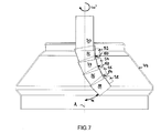
- Fig.7 shows a further embodiment with a distribution chute 20'" that comprises four interlinked chute sections 32, 34, 36, 38 forming a curved channel at a given speed of rotation ⁇ '.
- the distribution chute 20'" of Fig.7 comprises, for each chute section 32, 34, 36, 38, a corresponding unbalancing weight 52, 54, 56, 58 attached to its chute section 32, 34, 36, 38 respectively.
- Each of the three upper unbalancing weights 52, 54, 56, is configured and attached to its respective chute section 32, 34, 36, so as to form a mechanical limit stop 60, 62, 64 for limiting the maximum inclination of the subsequent, i.e. the chute section following downstream.
- each subsequent funnel shaped chute section 34, 36, 38 abuts to the lower face of the unbalancing weight 52, 54 or 56 respectively.
- Other configurations are also possible, e.g. with subsequent unbalancing weights abutting on each other.
- Fig.7 illustrates the maximum inclination angle ⁇ for the lowermost chute section 38. As is apparent from Fig.7, the inclination angle of each respective chute section 32, 34, 36, 38 increases from the uppermost chute section 32 to the lowermost chute section 38.
- limit stops also 60, 62, 64 also enable stabilization of the distribution chute 20'" in a maximum curvature configuration, in particular when the speed of rotation is set equal to or greater than the lowest speed at which all chute sections 32, 34, 36, 38 are at maximum inclination.
- the weight and the centripetal effect of the charge material on the distribution chute 20 have to be taken into account of course. This can be achieved through analytical or empirical methods readily available to those skilled in the art.
- circumferential distribution based on centrifugal curving of the distribution chute 20 can be achieved when the distribution chute 20 is balanced in rotation, it may be preferred to provide a distribution chute 20, 20' with a predetermined unbalanced configuration. Such predetermined unbalance can contribute to simplifying controlling the chute curvature and decrease the required speed of rotation for a given degree of curvature.
Abstract
A charging device for a shaft furnace comprises a distribution chute, which is supported rotatable about an essentially vertical axis of rotation, and a variable-speed drive connected to the distribution chute. The variable-speed drive is configured to rotate the distribution chute for circumferential distribution of bulk material on a charging surface of the shaft furnace. According to the invention, the distribution chute comprises multiple interlinked chute sections forming a curved channel for radial distribution of bulk material on the charging surface in function of the speed of rotation of the distribution chute.
Description
- In general, the present invention relates to the field of charging shaft furnaces and in particular it relates to a charging device for charging a shaft furnace such as a blast furnace.
- During the last decades a charging system well known by the name "bell-less top" (BLT) has found widespread use throughout the world for charging blast furnaces. This system includes a charging device with a distribution chute that is mounted rotatable about the vertical furnace axis and pivotable about a horizontal axis for distributing bulk material on the stockline. The charging device is further provided with drive equipment for rotating and pivoting the distribution chute according to the desired charging profile. Systems of this type have been disclosed for example in
WO 95/21272 US 5'022'806 ,US 4'941'792 ,US 3'814'403 andUS 3'693'812 . By rotating the chute about the vertical furnace axis and by varying the inclination of the chute, it is possible to direct bulk material (burden) to virtually any point of the charging surface. Accordingly, besides many other advantages, the BLT system enables a wide variety of charging profiles due to its versatility in distributing the burden on the charging surface. The charging device of the BLT system does however require highly developed drive equipment, in particular as regards the mechanism capable of rotating and simultaneously pivoting the distribution chute.
Hence, there is a desire for a simpler and less expensive solution as regards the drive equipment associated to the distribution chute. Obviously, such a simpler solution should not lack the desirable versatility in burden distribution. - Consequently, it is an object of the present invention to provide a charging device for a shaft furnace that allows great flexibility in distributing the burden without requiring highly developed drive equipment.
- In order to achieve this object, the present invention proposes a charging device for a shaft furnace comprising a distribution chute that is supported rotatable about an essentially vertical axis of rotation, and a variable-speed drive connected to the distribution chute in order to rotate the distribution chute for circumferentially distributing bulk material on a charging surface. According to the invention, the distribution chute comprises multiple interlinked chute sections forming a curved channel for radially distributing bulk material on the charging surface in function of the speed of rotation of the distribution chute.
- The invention is based on the principle that a suitably designed distribution chute may itself take a curved configuration due to the effect of the centrifugal force caused by rotation of the chute. Once the distribution chute has taken a curved configuration, a given radial velocity component can be imparted to the flow of bulk material (burden) descending there trough, without imposing on the chute any other constraint than rotation. In fact, the invention takes advantage of the effect exerted onto the chute sections of the distribution chute by the centrifugal force that depends on the speed of rotation of the distribution chute and its weight, including the weight of the burden within the chute. With the distribution chute according to the invention, the only actuation required for achieving burden distribution in both radial and circumferential direction is rotation of the chute. As a result, the required drive equipment is greatly simplified and less expensive when compared to prior art charging devices.
- In a further embodiment, the distribution chute is unbalanced with respect to its axis of rotation. Although adequate curvature of the burden flow channel could also be achieved with a chute that is balanced in rotation, an unbalance chute can achieve a certain degree of curvature at comparatively lower speed of rotation and may facilitate control of the degree of curvature, in particular when taking into account the centripetal effect of the burden flow on the chute.
- In a preferred embodiment, at least one chute section can comprise an unbalancing weight in order to unbalance the distribution chute. The unbalancing weight is arranged such that barycentre of the respective chute section is eccentric with respect to the axis of rotation at standstill. In order to unbalance the distribution chute, in case at least one pair of adjacent chute sections is interlinked by means of a revolute joint, this revolute joint may have its joint axis offset from the axis of rotation at standstill. Such offset may be provided as an alternative to or in complement to an unbalancing weight.
- Preferably, the distribution chute comprises at least three interlinked chute sections. The maximum inclination angle of the lowermost chute section, which determines the achievable burden distribution radius, increases with the amount of separate chute sections. Furthermore, the achievable overall degree of curvature and the smoothness of curvature of the distribution chute increases with the amount of distinct chute sections. In order to further increase the smoothness of curvature of the burden flow channel formed by the distribution chute, the chute sections advantageously have substantially equal length in flow direction.
- In a preferred embodiment, the chute sections are funnel shaped. Funnel shaped chute sections enable a partially interpenetrating overlapping arrangement of the chute sections so as to maintain a circumferentially and longitudinally enclosed channel up to maximum curvature of the articulated chute sections. Furthermore, in order to obtain a centering effect on the burden flow, it is preferred that, with respect to a pair of adjacent chute sections, the lower chute section is smaller than the upper chute section in terms of the funnel apex angle and the funnel outlet diameter.
- Advantageously, each pair of adjacent chute sections is interlinked, i.e. articulated, by means of a revolute joint. This simple form of articulating the chute sections minimizes the available degrees of freedom and thereby facilitates control of curvature, i.e. radial distribution of the burden. Preferably, with respect to a pair of adjacent chute sections, the revolute joint links the lower end portion of the upper chute section to the upper end portion of the lower chute section. In a mechanically simple configuration, the joint axes of the revolute joints are substantially perpendicular to the axis of rotation of the distribution chute and preferably parallel.
- Preferably, the chute sections are interlinked with freely pivotable joints configured such that the distribution chute forms a substantially vertical channel at standstill. In a preferred design, the distribution chute comprises a rotatably supported upper inlet channel connected to the variable-speed drive and wherein the uppermost chute section is linked to the lower end of the inlet channel. In yet another preferred embodiment the distribution chute comprises limit stops for limiting the maximum inclination angle of each chute section.
- As will be understood the charging device according to the invention is particularly suitable for equipping a blast furnace.
- Furthermore, the invention also concerns a distribution chute to be used in the charging device. This distribution chute comprises multiple interlinked chute sections capable of forming a curved channel for distributing bulk material radially on a charging surface in function of the speed of rotation of the distribution chute about its longitudinal axis.
- Further details and advantages of the present invention will be apparent from the following detailed description of several not limiting embodiments with reference to the attached drawings, wherein:
- Fig.1 is a vertical cross sectional view of a blast furnace throat schematically showing a distribution chute of a charging device at standstill;
- Fig.2 is a vertical cross sectional view according to Fig.1, schematically showing the distribution chute of a charging device at a given speed of rotation;
- Fig.3 is perspective view corresponding to Fig.2;
- Fig.4 is a schematic diagram of a first embodiment of a charging device;
- Fig.5 is a schematic diagram of a second embodiment of a charging device;
- Fig.6 is a schematic diagram of a third embodiment of a charging device;
- Fig.7 is a vertical cross sectional view schematically showing a distribution chute, of a fourth embodiment of a charging device, at a given speed of rotation.
- Identical reference numerals are used to identify identical or similar parts throughout the figures.
- Figs.4-6 schematically illustrate three embodiments of charging devices at standstill.
- A first embodiment of a charging device for a shaft furnace is generally identified by
reference numeral 10 in Fig4. As seen in Fig.4, the charging device comprises adistribution chute 20, that is rotatably supported within adrive housing 22 by means of asuitable bearing arrangement 24. A variable-speed drive 26, e.g. an electric motor, is connected to thedistribution chute 20 by means of a suitable toothed gearing 28. As will be appreciated, thecharging device 10 is configured to be arranged on the throat of a shaft furnace such as a blast furnace (not shown). Thecharging device 10 is configured concentrically to the vertical furnace axis A such that the longitudinal axis of the distribution chute 20 (at standstill) coincides with axis A. As is apparent from Figs.4-6, the variable-speed drive 26 serves to rotate thedistribution chute 20 about the vertical furnace axis A. - As further seen in Fig.4, the
distribution chute 20 is composed of several separate parts connected in lengthwise direction. From top to bottom,distribution chute 20 comprises anupper inlet channel 30 and first to fourthseparate chute sections chute sections revolute joints 40. In other words, thedistribution chute 20 forms a freely articulated chain of successive small chute members referred to aschute sections uppermost chute section 32 is linked to theinlet channel 30 which is rotatably supported by thedrive housing 22 through bearingarrangement 24. Therevolute joints 40 allow pivoting of thechute sections inlet channel 30. More precisely, each revolute joint 40 provides one rotational degree of freedom about a substantially horizontal joint axis (perpendicular to the plane of Fig.4 and axis A). In Fig.4, therevolute joints 40 are arranged with parallel joint axes that are coplanar at standstill of thedistribution chute 20. As further seen in Fig.4, therevolute joints 40 are arranged to connect and articulate the lower end portion of the adjacent upper chute section to the upper end portion of the adjacent lower chute section with respect to each pair of adjacent chute sections (32,34); (34,36); (36-38). Similarly, the uppermost revolute joint articulates the upper end of theuppermost chute section 32 to the lower end of theinlet channel 30. - The
inlet channel 30 is a cylindrical tube, into the upper end of which charge material is received during charging of the furnace. Eachchute section chute sections chute sections inlet channel 30 together with the concatenated interlinkedchute sections inlet channel 30 form a passage for charge material flowing downwardly there through. As regards weight distribution, thedistribution chute 20 of Fig.4, includinginlet channel 30 andchute sections - In Fig.5, a second embodiment of a charging device 10' comprises a distribution chute 20' that has a configuration generally similar to the previous embodiment. The distribution chute 20' differs from the
distribution chute 20 in that the lowermost revolute joint 41 has its joint axis slightly horizontally offset from the axis of rotation A at standstill. The joint axis of revolute joint 41 is parallel to the joint axes of the otherrevolute joints 40. The offset revolute joint 41 renders the distribution chute 20' unbalanced in rotation. As will be understood, such an offset may also be provided at a different joint axis or at various joint axes in order to unbalance the distribution chute 20'. - In Fig.6, a third embodiment of a charging
device 10" comprises adistribution chute 20" that has a configuration generally similar to the previous embodiments. Thedistribution chute 20" differs from thedistribution chute 20 in that it comprises an unbalancing weight 42 that is attached to one point or portion of the circumference of thelowermost chute section 38, in order to unbalance thedistribution chute 20" with respect to its axis of rotation A. By means of the unbalancing weight 42, the barycentre of thechute section 38 is made eccentric with respect to the longitudinal axis of thedistribution chute 20". As will be understood, such an unbalancing weight 42 may also be provided at a different chute section or at more than one or allchute sections distribution chute 20". Furthermore, an offset of one or more joint axes may be applied in combination with the unbalancing weight 42 if required. - The operation of a charging
device - Fig.1 shows the
distribution chute 20 at standstill, i.e. when thedistribution chute 20 is not rotating. As seen in Fig.1, thedistribution chute 20 together with the remaining parts of the charging device 10 (not shown) is installed on top of a blast furnace, i.e. on thefurnace throat 44. Thedistribution chute 20 forms an articulated tube that is substantially vertical at standstill due to the freely pivotablerevolute joints 40. It may be noted that at standstill thedistribution chute 20 permits centre charging, i.e. directing the burden into the centre region of the charging surface, also called stockline, of the furnace. Especially as regards centre charging, it will be appreciated that with respect to each pair of adjacent chute sections (32-34), (34-36), (36-38), the lower chute section is smaller than the upper chute section in terms of the funnel apex angle and the funnel outlet diameter as seen in Fig.1. Thereby a centering effect is achieved such that the flow of charge material is made to converge at the outlet of thelowermost chute section 38. Thereby, improved targeting of the charge material is achieved, both during centre charging and also during circumferential charging. - Fig.2 shows the configuration of the
distribution chute 20 at a given speed of rotation ω about axis A. As will be appreciated, thedistribution chute 20 is configured to form a curved channel for radially distributing bulk material on the charging surface in function of the speed of rotation ω of thedistribution chute 20. This is achieved due to the freely pivotable connection between thechute sections inlet channel 30 and by taking advantage of the effect of the centrifugal force. Since the centrifugal force is proportional to the square of the speed of rotation ω, the degree of curvature of thedistribution chute 20 and in consequence the point of impact of the burden in radial direction can be adjusted by adjusting the speed of rotation only. No further actuation of thedistribution chute 20 is required. Hence, by virtue of the design of the distribution chute 20 (20', 20" or 20"') the charging device 10 (or 10' or 10") allows circumferential and radial burden distribution only by means of rotation of thedistribution chute 20. Thereby the charging device 10 (or 10' or 10") enables achieving a wide variety of charging profiles without requiring a complex drive equipment. It should be noted that due to the funnel shaped configuration of thechute sections inlet channel 30 is achieved so as to maintain a circumferentially and lengthwise enclosed tubular channel for the burden up to the maximum degree of curvature. - Fig.3 illustrates the
curved distribution chute 20 as seen in Fig.2 in perspective view. Althoughchute sections lowermost chute section 38 in order to avoid unnecessary segregation. Furthermore, it should be noted that segregation is reduced over prior art devices due to the considerable total length of thedistribution chute 20 when compared to prior art chutes. - Fig.7 shows a further embodiment with a distribution chute 20'" that comprises four interlinked
chute sections chute section weight chute section upper unbalancing weights respective chute section mechanical limit stop upper inlet channel 30 or the uppermost revolute joint. At the speed of rotation ω' (and at any higher speed of rotation >ω' for a given mass flow of burden), the upper edge of each subsequent funnel shapedchute section weight chute section distribution chute 20"', a collision of the chute 20'" with the shell of the furnace can be avoided. Furthermore, the maximum radius to which burden can be charged is thereby limited, e.g. to avoid collision of charge material with the furnace shell. Fig.7 illustrates the maximum inclination angle α for thelowermost chute section 38. As is apparent from Fig.7, the inclination angle of eachrespective chute section uppermost chute section 32 to thelowermost chute section 38. It may be noted that, irrespective of the presence of limit stops, the overall achievable angle α for a given speed of rotation, will be dependent of and increase with the total number of chute sections. As will be appreciated, the limit stops also 60, 62, 64 also enable stabilization of the distribution chute 20'" in a maximum curvature configuration, in particular when the speed of rotation is set equal to or greater than the lowest speed at which allchute sections - When determining the relationship between speed of rotation and the radial point of impact, the weight and the centripetal effect of the charge material on the
distribution chute 20 have to be taken into account of course. This can be achieved through analytical or empirical methods readily available to those skilled in the art. Although circumferential distribution based on centrifugal curving of thedistribution chute 20 can be achieved when thedistribution chute 20 is balanced in rotation, it may be preferred to provide adistribution chute 20, 20' with a predetermined unbalanced configuration. Such predetermined unbalance can contribute to simplifying controlling the chute curvature and decrease the required speed of rotation for a given degree of curvature.
Claims (16)
- A charging device for a shaft furnace comprising
a distribution chute that is supported rotatable about an essentially vertical axis of rotation, and
a variable-speed drive connected to said distribution chute in order to rotate said distribution chute for circumferentially distributing bulk material on a charging surface,
characterized in that
said distribution chute comprises multiple interlinked chute sections forming a curved channel for radially distributing bulk material on said charging surface in function of the speed of rotation of said distribution chute. - The charging device according to claim 1, wherein said distribution chute is unbalanced with respect to its axis of rotation.
- The charging device according to claim 2, wherein at least one chute section comprises an unbalancing weight.
- The charging device according to claim 2 or 3, wherein at least one pair of adjacent chute sections is interlinked by means of a revolute joint having its joint axis offset from said axis of rotation at standstill.
- The charging device according to any one of claims 1 to 4, wherein said distribution chute comprises at least three interlinked chute sections.
- The charging device according to any one of claims 1 to 5, wherein said chute sections have substantially equal length in flow direction.
- The charging device according to any one of claims 1 to 6, wherein said chute sections are funnel shaped.
- The charging device according to claim 7, wherein, with respect to a pair of adjacent chute sections, the lower chute section is smaller than the upper chute section in terms of the funnel apex angle and the funnel outlet diameter.
- The charging device according to any one of the preceding claims, wherein each pair of adjacent chute sections is interlinked by means of a revolute joint.
- The charging device according to claim 9, wherein, with respect to a pair of adjacent chute sections, the revolute joint links the lower end portion of the upper chute section to the upper end portion of the lower chute section.
- The charging device according to claim 4, 9 or 10, wherein the joint axes of said revolute joints are substantially perpendicular to said axis of rotation of said distribution chute and preferably parallel.
- The charging device according to any one of the preceding claims, wherein said chute sections are interlinked with freely pivotable joints configured such that said distribution chute forms a substantially vertical channel at standstill.
- The charging device according to any one of the preceding claims, wherein said distribution chute comprises a rotatably supported upper inlet channel connected to said variable-speed drive and wherein the uppermost chute section is linked to the lower end of said inlet channel.
- The charging device according to any one of the preceding claims, wherein said distribution chute comprises limit stops for limiting the maximum inclination angle of each chute section.
- Blast furnace comprising a charging device according to any one of claims 1 to 14.
- Distribution chute for a charging device according to any one of claims 1 to 15, comprising multiple interlinked chute sections capable of forming a curved channel for distributing bulk material radially on a charging surface in function of the speed of rotation of said distribution chute about its longitudinal axis.
Priority Applications (10)
| Application Number | Priority Date | Filing Date | Title |
|---|---|---|---|
| EP06115836A EP1870651A1 (en) | 2006-06-21 | 2006-06-21 | Charging device for a shaft furnace |
| EP07729422A EP2032926B1 (en) | 2006-06-21 | 2007-05-23 | Charging device for a shaft furnace |
| PCT/EP2007/054984 WO2007147696A1 (en) | 2006-06-21 | 2007-05-23 | Charging device for a shaft furnace |
| RU2009101571/02A RU2431097C2 (en) | 2006-06-21 | 2007-05-23 | Loading device for shaft furnace |
| AT07729422T ATE462947T1 (en) | 2006-06-21 | 2007-05-23 | LOADING DEVICE FOR A SHAFT FURNACE |
| CN2007800230020A CN101473182B (en) | 2006-06-21 | 2007-05-23 | Charging device for a shaft furnace |
| US12/306,179 US20090180845A1 (en) | 2006-06-21 | 2007-05-23 | Charging device for a shaft furnace |
| BRPI0712049-4A BRPI0712049A2 (en) | 2006-06-21 | 2007-05-23 | loading device for a bowl oven |
| DE602007005641T DE602007005641D1 (en) | 2006-06-21 | 2007-05-23 | FEEDING DEVICE FOR A CHESS PLATE |
| UAA200900381A UA95295C2 (en) | 2006-06-21 | 2007-05-23 | Feeding device for shaft furnace |
Applications Claiming Priority (1)
| Application Number | Priority Date | Filing Date | Title |
|---|---|---|---|
| EP06115836A EP1870651A1 (en) | 2006-06-21 | 2006-06-21 | Charging device for a shaft furnace |
Publications (1)
| Publication Number | Publication Date |
|---|---|
| EP1870651A1 true EP1870651A1 (en) | 2007-12-26 |
Family
ID=37395291
Family Applications (2)
| Application Number | Title | Priority Date | Filing Date |
|---|---|---|---|
| EP06115836A Withdrawn EP1870651A1 (en) | 2006-06-21 | 2006-06-21 | Charging device for a shaft furnace |
| EP07729422A Expired - Fee Related EP2032926B1 (en) | 2006-06-21 | 2007-05-23 | Charging device for a shaft furnace |
Family Applications After (1)
| Application Number | Title | Priority Date | Filing Date |
|---|---|---|---|
| EP07729422A Expired - Fee Related EP2032926B1 (en) | 2006-06-21 | 2007-05-23 | Charging device for a shaft furnace |
Country Status (9)
| Country | Link |
|---|---|
| US (1) | US20090180845A1 (en) |
| EP (2) | EP1870651A1 (en) |
| CN (1) | CN101473182B (en) |
| AT (1) | ATE462947T1 (en) |
| BR (1) | BRPI0712049A2 (en) |
| DE (1) | DE602007005641D1 (en) |
| RU (1) | RU2431097C2 (en) |
| UA (1) | UA95295C2 (en) |
| WO (1) | WO2007147696A1 (en) |
Families Citing this family (8)
| Publication number | Priority date | Publication date | Assignee | Title |
|---|---|---|---|---|
| LU91716B1 (en) * | 2010-08-06 | 2012-02-07 | Wurth Paul Sa | Distribution chute |
| CN103243188A (en) * | 2012-02-10 | 2013-08-14 | 吴蔓洁 | Method and device for material distribution of blast furnace bell-less top |
| LU92046B1 (en) * | 2012-07-18 | 2014-01-20 | Wurth Paul Sa | Rotary charging device for shaft furnace |
| KR101609343B1 (en) | 2014-08-19 | 2016-04-05 | 주식회사 포스코 | Apparatus for guiding raw materials to raw materials storing system |
| ITUB20152684A1 (en) * | 2015-07-30 | 2017-01-30 | Danieli Off Mecc | DISTRIBUTION DEVICE FOR LOADING MATERIAL INSIDE A HILLFORLD |
| KR101853766B1 (en) | 2016-12-09 | 2018-05-02 | 주식회사 포스코 | Material Feeding Apparatus |
| CN108839332B (en) * | 2018-09-25 | 2020-05-19 | 汕头大洋兴福塑料机械有限公司 | Plastic film blowing machine |
| CN111349734B (en) * | 2020-03-31 | 2021-01-08 | 北京科技大学 | Blast furnace distributing device with movable feed opening |
Citations (3)
| Publication number | Priority date | Publication date | Assignee | Title |
|---|---|---|---|---|
| DE19929180A1 (en) * | 1999-06-25 | 2001-01-04 | Zimmermann & Jansen Gmbh | Feeding device for a shaft furnace |
| EP1493827A1 (en) * | 2003-06-20 | 2005-01-05 | Z & J Technologies GmbH | Charging hopper for a furnace |
| WO2006085795A1 (en) * | 2005-02-07 | 2006-08-17 | Obschestvo S Ogranichennoi Otvetstvennostyu 'issledovatelsko-Tekhnologichesky Tsentr 'ausferr' | Plant for supplying materials to a metallurgical device |
Family Cites Families (19)
| Publication number | Priority date | Publication date | Assignee | Title |
|---|---|---|---|---|
| US206001A (en) * | 1878-07-16 | Improvement in grain-spouts for elevators | ||
| US1268219A (en) * | 1917-03-06 | 1918-06-04 | James J Gerber | Distributing-spout. |
| US1629247A (en) * | 1924-09-13 | 1927-05-17 | Universal Broadcaster Mfg Co | Seed or fertilizer distributing machine |
| US3495878A (en) * | 1967-07-10 | 1970-02-17 | Toyo Pulp Co Ltd | Flexible pipe apparatus for pneumatically conveying bulk material |
| DE1800114A1 (en) * | 1968-10-01 | 1970-04-09 | Vni I P Ki Metall Masinostroje | Charge distribution in blast furnace charging device |
| LU59207A1 (en) * | 1969-07-31 | 1969-12-10 | Wurth Anciens Ets Paul | |
| LU65312A1 (en) * | 1972-05-08 | 1972-08-23 | ||
| JPS5222802B2 (en) * | 1973-10-12 | 1977-06-20 | ||
| US3949850A (en) * | 1974-11-07 | 1976-04-13 | Schumm H Dale | Spout construction for grain elevators and the like |
| CN86104795A (en) * | 1986-07-05 | 1987-04-15 | 林国护 | Steady ultra-high voltage working method of blast furnace and top arrangement |
| AT394631B (en) * | 1988-07-25 | 1992-05-25 | Wurth Paul Sa | HANDLING DEVICE FOR A DISTRIBUTION CHUTE OF A SHAFT STOVE, AND DRIVE MECHANISM ADAPTED TO THIS DEVICE |
| LU87341A1 (en) * | 1988-09-22 | 1990-04-06 | Wurth Paul Sa | LOADING SYSTEM FOR A TANK OVEN |
| LU88456A1 (en) * | 1994-02-01 | 1995-09-01 | Wurth Paul Sa | Bulk material distribution device |
| US5601181A (en) * | 1995-05-23 | 1997-02-11 | Lindhorst; Tim J. | Adjustable grain elevator spout |
| AU768056B2 (en) * | 1998-12-30 | 2003-11-27 | Sms Schloemann-Siemag Aktiengesellschaft | Bell and hopper for shaft furnaces |
| CN1384212A (en) * | 2001-01-17 | 2002-12-11 | 徐寿华 | Oscillating chute-type bell-free roof material distributor for blast furnace |
| LU90863B1 (en) * | 2001-12-13 | 2003-06-16 | Wurth Paul Sa | Charging device with rotary chute |
| DE10327276A1 (en) * | 2003-06-17 | 2005-01-05 | Z & J Technologies Gmbh | Device for closing or opening an opening, in particular bottom opening of a material bunker for a blast furnace |
| KR100985372B1 (en) * | 2003-07-09 | 2010-10-04 | 주식회사 포스코 | An apparatus for controlling a movement of ore chute in blast furnace |
-
2006
- 2006-06-21 EP EP06115836A patent/EP1870651A1/en not_active Withdrawn
-
2007
- 2007-05-23 DE DE602007005641T patent/DE602007005641D1/en active Active
- 2007-05-23 CN CN2007800230020A patent/CN101473182B/en not_active Expired - Fee Related
- 2007-05-23 WO PCT/EP2007/054984 patent/WO2007147696A1/en active Application Filing
- 2007-05-23 US US12/306,179 patent/US20090180845A1/en not_active Abandoned
- 2007-05-23 BR BRPI0712049-4A patent/BRPI0712049A2/en not_active IP Right Cessation
- 2007-05-23 UA UAA200900381A patent/UA95295C2/en unknown
- 2007-05-23 EP EP07729422A patent/EP2032926B1/en not_active Expired - Fee Related
- 2007-05-23 RU RU2009101571/02A patent/RU2431097C2/en not_active IP Right Cessation
- 2007-05-23 AT AT07729422T patent/ATE462947T1/en active
Patent Citations (3)
| Publication number | Priority date | Publication date | Assignee | Title |
|---|---|---|---|---|
| DE19929180A1 (en) * | 1999-06-25 | 2001-01-04 | Zimmermann & Jansen Gmbh | Feeding device for a shaft furnace |
| EP1493827A1 (en) * | 2003-06-20 | 2005-01-05 | Z & J Technologies GmbH | Charging hopper for a furnace |
| WO2006085795A1 (en) * | 2005-02-07 | 2006-08-17 | Obschestvo S Ogranichennoi Otvetstvennostyu 'issledovatelsko-Tekhnologichesky Tsentr 'ausferr' | Plant for supplying materials to a metallurgical device |
Also Published As
| Publication number | Publication date |
|---|---|
| EP2032926A1 (en) | 2009-03-11 |
| RU2009101571A (en) | 2010-07-27 |
| CN101473182A (en) | 2009-07-01 |
| BRPI0712049A2 (en) | 2012-01-10 |
| ATE462947T1 (en) | 2010-04-15 |
| US20090180845A1 (en) | 2009-07-16 |
| EP2032926B1 (en) | 2010-03-31 |
| CN101473182B (en) | 2011-04-27 |
| DE602007005641D1 (en) | 2010-05-12 |
| WO2007147696A1 (en) | 2007-12-27 |
| UA95295C2 (en) | 2011-07-25 |
| RU2431097C2 (en) | 2011-10-10 |
Similar Documents
| Publication | Publication Date | Title |
|---|---|---|
| EP2032926B1 (en) | Charging device for a shaft furnace | |
| US8800904B2 (en) | Cone crusher | |
| US4819331A (en) | Apparatus for cracking the husks of nuts | |
| US5799777A (en) | Device for the distribution of materials in bulk | |
| WO2003050314A1 (en) | Charging device with rotary chute | |
| US8376681B2 (en) | Charging device for a shaft furnace | |
| WO2011065513A1 (en) | Material segregation apparatus for blast furnace top bunker | |
| WO2009029982A1 (en) | Grinding mill and method of grinding | |
| CN102459653A (en) | Device for distributing charge material in a shaft furnace | |
| EP2601319B1 (en) | Distribution chute | |
| KR101541426B1 (en) | Pulverizer having improved vane wheel | |
| JP2921380B2 (en) | Electric arc furnace with pre-tropics | |
| CN206939959U (en) | A kind of cylindrical element self-feeding bin device | |
| JPH10501026A (en) | Blast furnace loading device with rotating chute | |
| JP3777654B2 (en) | Furnace top charging equipment | |
| JP7154101B2 (en) | Furnace equipment | |
| JPS6241955Y2 (en) | ||
| JPS61272585A (en) | Bell-less type furnace top charger | |
| RU2374326C2 (en) | Device for distribution of loaded bulk material | |
| KR20210022644A (en) | Device for continuously weighing pourable materials | |
| CN111169669A (en) | Speed-adjustable powder blanking device | |
| CZ9904036A3 (en) | Device for separation of loose material containing rotary trough with variable angle of inclination | |
| GB2296759A (en) | Shaft furnace charge distributor | |
| JPS6123843B2 (en) | ||
| JPS5858211A (en) | Top charging device for blast furnace |
Legal Events
| Date | Code | Title | Description |
|---|---|---|---|
| PUAI | Public reference made under article 153(3) epc to a published international application that has entered the european phase |
Free format text: ORIGINAL CODE: 0009012 |
|
| AK | Designated contracting states |
Kind code of ref document: A1 Designated state(s): AT BE BG CH CY CZ DE DK EE ES FI FR GB GR HU IE IS IT LI LT LU LV MC NL PL PT RO SE SI SK TR |
|
| AX | Request for extension of the european patent |
Extension state: AL BA HR MK YU |
|
| AKX | Designation fees paid | ||
| REG | Reference to a national code |
Ref country code: DE Ref legal event code: 8566 |
|
| STAA | Information on the status of an ep patent application or granted ep patent |
Free format text: STATUS: THE APPLICATION IS DEEMED TO BE WITHDRAWN |
|
| 18D | Application deemed to be withdrawn |
Effective date: 20080627 |