EP1870347B1 - Stopper for flasks of sterile products and use of said stopper in sterile measured filling - Google Patents
Stopper for flasks of sterile products and use of said stopper in sterile measured filling Download PDFInfo
- Publication number
- EP1870347B1 EP1870347B1 EP20070380135 EP07380135A EP1870347B1 EP 1870347 B1 EP1870347 B1 EP 1870347B1 EP 20070380135 EP20070380135 EP 20070380135 EP 07380135 A EP07380135 A EP 07380135A EP 1870347 B1 EP1870347 B1 EP 1870347B1
- Authority
- EP
- European Patent Office
- Prior art keywords
- stopper
- flask
- plug
- protector
- stoppered
- Prior art date
- Legal status (The legal status is an assumption and is not a legal conclusion. Google has not performed a legal analysis and makes no representation as to the accuracy of the status listed.)
- Not-in-force
Links
Images


Classifications
-
- B—PERFORMING OPERATIONS; TRANSPORTING
- B65—CONVEYING; PACKING; STORING; HANDLING THIN OR FILAMENTARY MATERIAL
- B65D—CONTAINERS FOR STORAGE OR TRANSPORT OF ARTICLES OR MATERIALS, e.g. BAGS, BARRELS, BOTTLES, BOXES, CANS, CARTONS, CRATES, DRUMS, JARS, TANKS, HOPPERS, FORWARDING CONTAINERS; ACCESSORIES, CLOSURES, OR FITTINGS THEREFOR; PACKAGING ELEMENTS; PACKAGES
- B65D51/00—Closures not otherwise provided for
- B65D51/18—Arrangements of closures with protective outer cap-like covers or of two or more co-operating closures
-
- A—HUMAN NECESSITIES
- A61—MEDICAL OR VETERINARY SCIENCE; HYGIENE
- A61L—METHODS OR APPARATUS FOR STERILISING MATERIALS OR OBJECTS IN GENERAL; DISINFECTION, STERILISATION OR DEODORISATION OF AIR; CHEMICAL ASPECTS OF BANDAGES, DRESSINGS, ABSORBENT PADS OR SURGICAL ARTICLES; MATERIALS FOR BANDAGES, DRESSINGS, ABSORBENT PADS OR SURGICAL ARTICLES
- A61L2/00—Disinfection or sterilisation of materials or objects, in general; Accessories therefor
- A61L2/02—Disinfection or sterilisation of materials or objects, in general; Accessories therefor using physical processes
- A61L2/04—Heat
- A61L2/06—Hot gas
- A61L2/07—Steam
-
- A—HUMAN NECESSITIES
- A61—MEDICAL OR VETERINARY SCIENCE; HYGIENE
- A61J—CONTAINERS SPECIALLY ADAPTED FOR MEDICAL OR PHARMACEUTICAL PURPOSES; DEVICES OR METHODS SPECIALLY ADAPTED FOR BRINGING PHARMACEUTICAL PRODUCTS INTO PARTICULAR PHYSICAL OR ADMINISTERING FORMS; DEVICES FOR ADMINISTERING FOOD OR MEDICINES ORALLY; BABY COMFORTERS; DEVICES FOR RECEIVING SPITTLE
- A61J1/00—Containers specially adapted for medical or pharmaceutical purposes
- A61J1/14—Details; Accessories therefor
- A61J1/1412—Containers with closing means, e.g. caps
- A61J1/1425—Snap-fit type
-
- A—HUMAN NECESSITIES
- A61—MEDICAL OR VETERINARY SCIENCE; HYGIENE
- A61J—CONTAINERS SPECIALLY ADAPTED FOR MEDICAL OR PHARMACEUTICAL PURPOSES; DEVICES OR METHODS SPECIALLY ADAPTED FOR BRINGING PHARMACEUTICAL PRODUCTS INTO PARTICULAR PHYSICAL OR ADMINISTERING FORMS; DEVICES FOR ADMINISTERING FOOD OR MEDICINES ORALLY; BABY COMFORTERS; DEVICES FOR RECEIVING SPITTLE
- A61J1/00—Containers specially adapted for medical or pharmaceutical purposes
- A61J1/14—Details; Accessories therefor
- A61J1/1443—Containers with means for dispensing liquid medicaments in a filtered or sterile way, e.g. with bacterial filters
-
- A—HUMAN NECESSITIES
- A61—MEDICAL OR VETERINARY SCIENCE; HYGIENE
- A61L—METHODS OR APPARATUS FOR STERILISING MATERIALS OR OBJECTS IN GENERAL; DISINFECTION, STERILISATION OR DEODORISATION OF AIR; CHEMICAL ASPECTS OF BANDAGES, DRESSINGS, ABSORBENT PADS OR SURGICAL ARTICLES; MATERIALS FOR BANDAGES, DRESSINGS, ABSORBENT PADS OR SURGICAL ARTICLES
- A61L2/00—Disinfection or sterilisation of materials or objects, in general; Accessories therefor
- A61L2/24—Apparatus using programmed or automatic operation
-
- B—PERFORMING OPERATIONS; TRANSPORTING
- B65—CONVEYING; PACKING; STORING; HANDLING THIN OR FILAMENTARY MATERIAL
- B65D—CONTAINERS FOR STORAGE OR TRANSPORT OF ARTICLES OR MATERIALS, e.g. BAGS, BARRELS, BOTTLES, BOXES, CANS, CARTONS, CRATES, DRUMS, JARS, TANKS, HOPPERS, FORWARDING CONTAINERS; ACCESSORIES, CLOSURES, OR FITTINGS THEREFOR; PACKAGING ELEMENTS; PACKAGES
- B65D51/00—Closures not otherwise provided for
- B65D51/002—Closures to be pierced by an extracting-device for the contents and fixed on the container by separate retaining means
-
- A—HUMAN NECESSITIES
- A61—MEDICAL OR VETERINARY SCIENCE; HYGIENE
- A61J—CONTAINERS SPECIALLY ADAPTED FOR MEDICAL OR PHARMACEUTICAL PURPOSES; DEVICES OR METHODS SPECIALLY ADAPTED FOR BRINGING PHARMACEUTICAL PRODUCTS INTO PARTICULAR PHYSICAL OR ADMINISTERING FORMS; DEVICES FOR ADMINISTERING FOOD OR MEDICINES ORALLY; BABY COMFORTERS; DEVICES FOR RECEIVING SPITTLE
- A61J1/00—Containers specially adapted for medical or pharmaceutical purposes
- A61J1/14—Details; Accessories therefor
- A61J1/1468—Containers characterised by specific material properties
-
- B—PERFORMING OPERATIONS; TRANSPORTING
- B65—CONVEYING; PACKING; STORING; HANDLING THIN OR FILAMENTARY MATERIAL
- B65D—CONTAINERS FOR STORAGE OR TRANSPORT OF ARTICLES OR MATERIALS, e.g. BAGS, BARRELS, BOTTLES, BOXES, CANS, CARTONS, CRATES, DRUMS, JARS, TANKS, HOPPERS, FORWARDING CONTAINERS; ACCESSORIES, CLOSURES, OR FITTINGS THEREFOR; PACKAGING ELEMENTS; PACKAGES
- B65D2251/00—Details relating to container closures
- B65D2251/0003—Two or more closures
- B65D2251/0006—Upper closure
- B65D2251/0015—Upper closure of the 41-type
-
- B—PERFORMING OPERATIONS; TRANSPORTING
- B65—CONVEYING; PACKING; STORING; HANDLING THIN OR FILAMENTARY MATERIAL
- B65D—CONTAINERS FOR STORAGE OR TRANSPORT OF ARTICLES OR MATERIALS, e.g. BAGS, BARRELS, BOTTLES, BOXES, CANS, CARTONS, CRATES, DRUMS, JARS, TANKS, HOPPERS, FORWARDING CONTAINERS; ACCESSORIES, CLOSURES, OR FITTINGS THEREFOR; PACKAGING ELEMENTS; PACKAGES
- B65D2251/00—Details relating to container closures
- B65D2251/0003—Two or more closures
- B65D2251/0068—Lower closure
- B65D2251/009—Lower closure of the 51-type
Definitions
- the present invention relates to a stopper for flasks according to the preamble of claim 1, especially for flasks of sterile products, and to the use of same in a method of sterile measured filling of flasks.
- the stopper of the present invention is especially suitable as a stopper for vials the sterile contents of which are sealed and are to be administered by injection.
- the document US5718348 discloses a device according to the preamble of claim 1 meant to perform a process similar to the one described above by implementing a sealing plug and a protective cover used in conjunction with a flask with two protuberances.
- a first entity inserts this sealing plug from a flared part of the protective cover until it reaches a rib, then, a second entity locates the protective cover with the sealing plug over the flask making a tab engage the first protuberance located on the mouth of the flask.
- the device is pressed downwardly to make the plug reach a recess and get in a sealed position with respect to the protective cover and finally the flask is filled and the device is put over the flask and press downwardly until the tab engages the second protuberance located on the neck of the flask.
- the documents ES2016490 and ES2232269 disclose a method of sterile measured filling of flasks, preferably of vials, which comprises the steps of placing a stopper on a flask in a pre-stoppered position, placing a protector thereon, sterilising the flask in an autoclave with the stopper and the protector in a pre-closed position, cooling the flask-stopper-protector assembly, removal of the protector and the stopper, measured filling of the contents of the container into the latter, and closing the flask with the stopper.
- the protector and the stopper exert a labyrinth closure action which permits the sterilisation of the interior of the container in the autoclave, but prevents the entry of particles which might be present in the non-sterile air.
- the stopper After the measured filling, the stopper is inserted fully into the mouth of the container. Since the stopper includes a metal capsule, the final sealing of the container is obtained by deformation of said capsule (encapsulation or beading of the capsule). In accordance sterility of the whole owing to the labyrinth closure effect which is established between the skirts or walls of the protector and the wall of the flask or vial.
- the present invention discloses a stopper for a flask, especially a flask for pharmaceutical products, characterized in that it comprises, in combination,
- the length of the extension of the lateral wall of the protector will be equal to or greater than the travel of the stopper between the stoppered position and the pre-stoppered position.
- the stopper of the present invention has the advantage of providing a labyrinth type closure against the particles in suspension in the air during the aforesaid processes of sterile measured filling, both in the stoppered position and in the pre-stoppered position.
- the labyrinth closure does not prevent the sterilising steam in the autoclave from penetrating, thereby making it possible to sterilise the flask in the pre-stoppered position, minimising the time for which the inside of the flask is exposed to the ambient air during the measured filling process.
- the stopper of the present invention by having the plug and the protector already joined to each other, provides the system with the following savings:
- Another additional advantage of the present invention lies in the fact that the conventional beading of the metal capsules generates particles which require the separation of the processes of measured filling and beading, an action which is unnecessary with the present invention.
- the extension of the lateral wall may be defined as an extension of the projection of the lateral wall, as a straight extension of the lateral wall, as a conical extension below the projection of the lateral wall, or as a combination of a conical extension with a cylindrical end.
- the stopper of the present invention in addition makes it possible to arrange an upper pull-off lid on the stopper.
- the protector may have an upper lid which gives access, via a window, to the plug made of rubbery material (rubber).
- This preferred embodiment will be directed especially to vials for sterile pharmaceutical products for intravenous administration.
- the present invention also comprises the use of the stopper of the present invention in a process of sterile measured filling of flasks for pharmaceutical products.
- this process comprises, at least, the following steps:
- FIGs 1 to 3 an exemplary embodiment of the stopper 2 of the present invention can be seen in the stoppered position, closing a vial 1 for medicinal products.
- the stopper 2 has an upper lid 22 which can be removed by being pulled off, and a lateral wall 23 which has an extension 25, which in the examples shown extends almost to touch the shoulder 13 (transition zone between the neck 12 and the main body of the vial 1), in such a way that the small gap between the shoulder 13 and the extension 25 forms a labyrinth closure for the ambient air, since it is complicated for any possible particles present in the ambient air to pass through the existing gap in a direction opposed to gravity.
- the stopper 2 shown in the examples is composed of a plug 24, made of an elastomer, such as rubber.
- the plug 24 may have a special geometry which allows the stopper to rest in the mouth of the container (pre-stoppering) owing to a stepped contour (not shown).
- the plug 24 may have grooves 211 to permit, in the pre-stoppered position, the passage and emergence of the steam which will sterilise the container in the autoclave.
- the plug 24 also comprises an upper wall 21 for stoppering the bottle. This wall 21, made of rubbery material, makes it possible to be traversed by the needle of a syringe for the extraction of the pharmaceutical product from the interior without the need to open the stopper, which would expose the contents to the atmosphere.
- the stopper shown also has a protector joined to the plug by insertion or assembly, or by any other means, of the plug inside the protector in a previous process not described herein.
- the protector comprises the aforesaid lateral wall 23, which will preferably be made of synthetic material, such as a plastics material, and the removable lid 22.
- Said lateral wall has on its inner wall a projection 26 for engagement with the annular protuberance 14 of the neck of the vial 1 in the mouth region.
- Said projection may be arranged along the entire perimeter of the inner face of the lateral wall 23 or at a specific number of points.
- the lateral wall 23 has an extension 25 which, in the example of Figures 1 to 3 , is in the shape of an extension of the projection and the free end of which extends so that it almost touches the shoulder 13 of the vial 1. In this way, a labyrinth closure is established against the contaminating particles which may be suspended in the ambient air.
- the lower end of the plug 24 has an inclined/stepped wall which makes it possible to define a pre-stoppered position of the flask, in which the stopper rests, for example, on the inner edge of the mouth of the container 14 and the inner surface of the neck 11 of the container.
- the extension of the lateral wall 25 it is preferable for the extension of the lateral wall 25 to have a length, from the upper point of the projection 26 to its free end, equal to or greater than the travel of the stopper 2 between the pre-stoppered position and the stoppered position.
- the extension 25 and the annular protuberance of the mouth 14 of the container are close to each other, almost touching each other, so that in the pre-stoppered position the extension 25 of the lateral wall 23 also forms with the flask 1 a labyrinth closure with respect to the particles in suspension in the air.
- the extension 25 of the lateral wall of the stopper 2 may be of various shapes.
- the extension 25 has a conical section with a cylindrical free end zone.
- the extension 25 is conical in shape on the outside.
- the extension 25 is cylindrical in shape on the outside and its free end is likewise cylindrical.
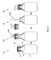
- Figure 7 shows an example of the use of a stopper 2 according to the present invention in a flask for pharmaceutical products, more specifically a vial 1.
- the method shown includes a first step of placing the stopper 2 on the flask 1 in a pre-stoppered position; in this position a step 101 of sterilisation in an autoclave is then carried out.
- a first sub-step 102 of removal of the stopper prlug and protector
- the measured filling of the pharmaceutical product into the flask takes place, for which a first sub-step 102 of removal of the stopper (plug and protector) is carried out with a single implement 1001, followed by a second sub-step of filling 103 with a specific implement 1002 and then closure 104 of the stopper 2 on the flask 1 as far as the closed position, which can be performed, if desired, by means of the same implement 1001 which was used to separate the stopper from the flask.
- the invention is not necessarily limited to same.
- said stopper may also be applied to flasks in which the neck has the same dimensions as the main body of the flask.
Landscapes
- Health & Medical Sciences (AREA)
- Veterinary Medicine (AREA)
- Life Sciences & Earth Sciences (AREA)
- Animal Behavior & Ethology (AREA)
- General Health & Medical Sciences (AREA)
- Public Health (AREA)
- Mechanical Engineering (AREA)
- Engineering & Computer Science (AREA)
- Pharmacology & Pharmacy (AREA)
- Epidemiology (AREA)
- Medical Preparation Storing Or Oral Administration Devices (AREA)
- Closures For Containers (AREA)
- Sampling And Sample Adjustment (AREA)
Abstract
Description
- The present invention relates to a stopper for flasks according to the preamble of
claim 1, especially for flasks of sterile products, and to the use of same in a method of sterile measured filling of flasks. - More particularly, the stopper of the present invention is especially suitable as a stopper for vials the sterile contents of which are sealed and are to be administered by injection.
- However, specific embodiments of the present invention are not necessarily confined to the applications cited.
- The document
US5718348 discloses a device according to the preamble ofclaim 1 meant to perform a process similar to the one described above by implementing a sealing plug and a protective cover used in conjunction with a flask with two protuberances. A first entity inserts this sealing plug from a flared part of the protective cover until it reaches a rib, then, a second entity locates the protective cover with the sealing plug over the flask making a tab engage the first protuberance located on the mouth of the flask. Then, after the flask is lyophilized, the device is pressed downwardly to make the plug reach a recess and get in a sealed position with respect to the protective cover and finally the flask is filled and the device is put over the flask and press downwardly until the tab engages the second protuberance located on the neck of the flask. - Furthermore the lyophilization process described on document
US5718348 is made with the plug covering the mouth of the flask and there is no guarantee that the plug does not cover completely the mouth of the flask, being not ensured the entrance of cleaning means into the flask. - The documents
ES2016490 ES2232269 - After the measured filling, the stopper is inserted fully into the mouth of the container. Since the stopper includes a metal capsule, the final sealing of the container is obtained by deformation of said capsule (encapsulation or beading of the capsule). In accordance sterility of the whole owing to the labyrinth closure effect which is established between the skirts or walls of the protector and the wall of the flask or vial.
- It is an aim of the present invention to disclose means which permit the simplification, reduction of costs and increase in safety in the aforesaid method.
- For this purpose, the present invention discloses a stopper for a flask, especially a flask for pharmaceutical products, characterized in that it comprises, in combination,
- a plug with resilient means for adjustment to the inner face of the neck of a flask and an upper surface for stoppering the aperture or mouth of the flash;
- means for defining a position for pre-stoppering of the flask, before the stoppered position, in which the resilient adjustment means are not fully inside the neck of the bottle;
- a protector joined to the plug which comprises a lateral wall, said lateral wall having on its inner face a projection for engagement with an annular protuberance forming the mouth of the container in the aforesaid stoppered position;
- Preferably, in order to perform the required functions, the length of the extension of the lateral wall of the protector, from the upper point of the projection to its free end, will be equal to or greater than the travel of the stopper between the stoppered position and the pre-stoppered position.
- The stopper of the present invention has the advantage of providing a labyrinth type closure against the particles in suspension in the air during the aforesaid processes of sterile measured filling, both in the stoppered position and in the pre-stoppered position. However, given their different physical states, the labyrinth closure does not prevent the sterilising steam in the autoclave from penetrating, thereby making it possible to sterilise the flask in the pre-stoppered position, minimising the time for which the inside of the flask is exposed to the ambient air during the measured filling process. On the other hand, the stopper of the present invention, by having the plug and the protector already joined to each other, provides the system with the following savings:
- of logistical type: it is only necessary to provide and handle one part where two were handled before.
- of economic type, in addition, since owing to the protuberance of the inside of the lateral wall of the protector it is not necessary to carry out the operation of closure by deformation of the metal capsule (beading).
- This brings with it a significant saving of time, simplification of the equipment, and the reduction of overall costs.
- Another additional advantage of the present invention lies in the fact that the conventional beading of the metal capsules generates particles which require the separation of the processes of measured filling and beading, an action which is unnecessary with the present invention.
- The extension of the lateral wall may be defined as an extension of the projection of the lateral wall, as a straight extension of the lateral wall, as a conical extension below the projection of the lateral wall, or as a combination of a conical extension with a cylindrical end.
- The stopper of the present invention in addition makes it possible to arrange an upper pull-off lid on the stopper. In this case, the protector may have an upper lid which gives access, via a window, to the plug made of rubbery material (rubber). This preferred embodiment will be directed especially to vials for sterile pharmaceutical products for intravenous administration.
- As a consequence of all the above, the present invention also comprises the use of the stopper of the present invention in a process of sterile measured filling of flasks for pharmaceutical products. Preferably this process comprises, at least, the following steps:
- placing the stopper on the flask, in a pre-stoppered position,
- sterilisation in an autoclave, preferably with vacuum cycles,
- preferably, a cooling step,
- extraction of the stopper,
- measured filling of the contents of the flask,
- closure of the flask, placing the stopper in the stoppered position.
- This method will be especially useful in the case where the flask is a vial for pharmaceutical products for intravenous administration.
- For greater understanding of the invention, drawings of some embodiments of the present invention are appended by way of non-limiting example.
-
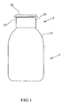
Figure 1 shows a front view of a flask assembly for a pharmaceutical product, stoppered by means of a stopper according to the present invention. -
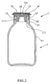
Figure 2 shows a cross-section through the assembly ofFigure 1 . -
Figure 3 shows a detail of the stopper ofFigure 2 . -
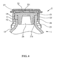
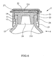
Figures 4 ,5 and6 show three alternative embodiments of the stopper according to the present invention. -
Figure 7 shows diagrammatically a process of sterilisation and measured filling in which a stopper according to the present invention is used. - In
Figures 1 to 3 an exemplary embodiment of thestopper 2 of the present invention can be seen in the stoppered position, closing avial 1 for medicinal products. - As can be seen from the outside, the
stopper 2 has anupper lid 22 which can be removed by being pulled off, and alateral wall 23 which has anextension 25, which in the examples shown extends almost to touch the shoulder 13 (transition zone between theneck 12 and the main body of the vial 1), in such a way that the small gap between theshoulder 13 and theextension 25 forms a labyrinth closure for the ambient air, since it is complicated for any possible particles present in the ambient air to pass through the existing gap in a direction opposed to gravity. - Internally, the
stopper 2 shown in the examples is composed of aplug 24, made of an elastomer, such as rubber. Theplug 24 may have a special geometry which allows the stopper to rest in the mouth of the container (pre-stoppering) owing to a stepped contour (not shown). In addition, theplug 24 may havegrooves 211 to permit, in the pre-stoppered position, the passage and emergence of the steam which will sterilise the container in the autoclave. Theplug 24 also comprises anupper wall 21 for stoppering the bottle. Thiswall 21, made of rubbery material, makes it possible to be traversed by the needle of a syringe for the extraction of the pharmaceutical product from the interior without the need to open the stopper, which would expose the contents to the atmosphere. - The stopper shown also has a protector joined to the plug by insertion or assembly, or by any other means, of the plug inside the protector in a previous process not described herein. The protector comprises the aforesaid
lateral wall 23, which will preferably be made of synthetic material, such as a plastics material, and theremovable lid 22. Said lateral wall has on its inner wall aprojection 26 for engagement with theannular protuberance 14 of the neck of thevial 1 in the mouth region. Said projection may be arranged along the entire perimeter of the inner face of thelateral wall 23 or at a specific number of points. Starting from theaforesaid projection 26, thelateral wall 23 has anextension 25 which, in the example ofFigures 1 to 3 , is in the shape of an extension of the projection and the free end of which extends so that it almost touches theshoulder 13 of thevial 1. In this way, a labyrinth closure is established against the contaminating particles which may be suspended in the ambient air. - In use, with the stopper in the closed position shown in
Figures 1 to 6 , it is possible to pull off theupper lid 22, which in this way acts as an upper pull-off enclosure. Beneath saidenclosure 22 there is anotherupper lid 27 which has awindow 231 which gives access to theupper wall 21 of therubber plug 24, allowing it to be punctured by the needle of a syringe. - Similarly, in the example shown, the lower end of the
plug 24 has an inclined/stepped wall which makes it possible to define a pre-stoppered position of the flask, in which the stopper rests, for example, on the inner edge of the mouth of thecontainer 14 and the inner surface of theneck 11 of the container. In said position, it is preferable for the extension of thelateral wall 25 to have a length, from the upper point of theprojection 26 to its free end, equal to or greater than the travel of thestopper 2 between the pre-stoppered position and the stoppered position. In this way, in the pre-stoppered position, theextension 25 and the annular protuberance of themouth 14 of the container are close to each other, almost touching each other, so that in the pre-stoppered position theextension 25 of thelateral wall 23 also forms with the flask 1 a labyrinth closure with respect to the particles in suspension in the air. - Naturally, the
extension 25 of the lateral wall of thestopper 2 may be of various shapes. InFigure 4 , theextension 25 has a conical section with a cylindrical free end zone. InFigure 5 , theextension 25 is conical in shape on the outside. InFigure 6 , theextension 25 is cylindrical in shape on the outside and its free end is likewise cylindrical. -
Figure 7 shows an example of the use of astopper 2 according to the present invention in a flask for pharmaceutical products, more specifically avial 1. - The method shown includes a first step of placing the
stopper 2 on theflask 1 in a pre-stoppered position; in this position astep 101 of sterilisation in an autoclave is then carried out. After the process of sterilisation in an autoclave and, optionally, cooling, the measured filling of the pharmaceutical product into the flask takes place, for which afirst sub-step 102 of removal of the stopper (plug and protector) is carried out with a single implement 1001, followed by a second sub-step of filling 103 with a specific implement 1002 and thenclosure 104 of thestopper 2 on theflask 1 as far as the closed position, which can be performed, if desired, by means of the same implement 1001 which was used to separate the stopper from the flask. Once the container is closed, no beading operation is required, since the sealing thereof is obtained by clipping the protector onto the container. - It is therefore clear that the significant economy which is obtained in this method by using the stopper of the present invention, in comparison with methods of known type, in which use was made of a stopper (which included a metal capsule) and a protector as two separate parts, without any join.
- Although a description has been given of some examples of preferred use of the stopper described, the invention is not necessarily limited to same. In particular, although applications have been shown in which the flask has a narrowed neck, said stopper may also be applied to flasks in which the neck has the same dimensions as the main body of the flask.
- Although the invention has been described with respect to preferred exemplary embodiments, these should not be regarded as limiting the invention, which will be defined by the widest interpretation of the following claims.
Claims (17)
- A flask stopper (12), which comprises, in combination:- a plug (24) with resilient means for adjustment to the inner face of the neck of a flask and an upper surface for stoppering the opening or mouth of the flask;- means for defining a position for pre-stoppering of the flask, before the stoppered position, in which the resilient adjustment means are not fully inside the neck of the bottle; characterized in that it comprises- a protector (23,27) joined to the plug (24) which comprises a lateral wall, said lateral wall having on its inner face a projection for engagement with the annular protuberance forming the mouth of the container in the aforesaid stoppered position;the aforesaid protector having an extension starting from the aforesaid projection to form, together with the transition zone between the neck and the main body of the flask, in the pre-stoppered position, a labyrinth closure allowing steam to enter the flask but keeping the particles in suspension in the air surrounding the flask from entering.
- A stopper (2) according to claim 1, characterized in that the length of the extension of the lateral wall of the protector, from the upper point of the projection to its free end, is equal to or greater than the travel of the stopper (2) between the stoppered position and the pre-stoppered position.
- A stopper (2) according to claim 1 or claim 2, characterized in that the aforesaid extension is cylindrical in shape on the outside.
- A stopper (2) according to claim 1 or claim 2, characterized in that the aforesaid extension is conical in shape on the outside.
- A stopper (2) according to claim 1 or claim 2, characterized in that the aforesaid extension has a conical section with a cylindrical free end zone.
- A stopper (2) according to any one of claims 1 to 5, characterized in that it has a pull-off upper enclosure.
- A stopper (2) according to any one of claims 1 to 6, characterized in that the protector has an upper lid (22) with a window which gives access to the plug.
- A stopper (2) according to any one of claims 1 to 7, characterized in that the plug (24) is made of rubber.
- A stopper (2) according to any one of claims 1 to 8, characterized in that the protector is made of synthetic material.
- A stopper (2) according to any one of claims 1 to 9, characterized in that the means for defining a pre-stoppering position comprise a stepped contour on the plug.
- A stopper (2) according to any one of claims 1 to 10, characterized in that the plug (24), in the pre-stoppered position, forms a labyrinth closure together with the inner face of the annular rim of the mouth of the flask.
- A stopper (2) according to any one of claims 1 to 11, characterized in that the plug (24) has a groove (211) which, in the pre-stoppered position, permits the passage and emergence of steam from inside the flask.
- The use of a stopper according to any one of claims 1 to 12 in a method of sterile measured filling of flasks of pharmaceutical products.
- The use according to claim 13, characterized in that the method of sterile measured filling comprises the following steps:- placing the stopper on the flask, in the pre-stoppered position;- sterilisation in an autoclave;- measured filling of the pharmaceutical product into the flask;- closing the flask with the stopper, as far as its stoppered position.
- The use according to claim 14, in which sterilisation takes place with the stopper on the flask, in its pre-stoppered position.
- The use according to any one of claims 13 to 15, characterized in that the flask is a vial for pharmaceutical products for intravenous administration.
- The use according to any one of claims 14 to 16, characterized in that the method proceeds to a cooling step between the sterilisation in an autoclave and the measured filling of the product.
Applications Claiming Priority (1)
| Application Number | Priority Date | Filing Date | Title |
|---|---|---|---|
| ES200601691A ES2261104B1 (en) | 2006-06-19 | 2006-06-19 | "PLUG FOR STERILE PRODUCTS FRUITS AND USE OF SUCH PLUG IN STERILE DOSAGE". |
Publications (3)
| Publication Number | Publication Date |
|---|---|
| EP1870347A2 EP1870347A2 (en) | 2007-12-26 |
| EP1870347A3 EP1870347A3 (en) | 2009-09-30 |
| EP1870347B1 true EP1870347B1 (en) | 2011-06-15 |
Family
ID=37310396
Family Applications (1)
| Application Number | Title | Priority Date | Filing Date |
|---|---|---|---|
| EP20070380135 Not-in-force EP1870347B1 (en) | 2006-06-19 | 2007-05-11 | Stopper for flasks of sterile products and use of said stopper in sterile measured filling |
Country Status (6)
| Country | Link |
|---|---|
| US (1) | US20080000870A1 (en) |
| EP (1) | EP1870347B1 (en) |
| JP (1) | JP2008001430A (en) |
| AT (1) | ATE512899T1 (en) |
| CA (1) | CA2588426C (en) |
| ES (2) | ES2261104B1 (en) |
Families Citing this family (18)
| Publication number | Priority date | Publication date | Assignee | Title |
|---|---|---|---|---|
| JP5231794B2 (en) | 2007-12-10 | 2013-07-10 | 株式会社大協精工 | Plastic cap for vials |
| ITMO20080160A1 (en) * | 2008-05-27 | 2009-11-28 | Lameplast Spa | BOTTLE FOR THE CONTAINMENT OF INJECTABLE FLUIDS, PARTICULARLY MEDICAL, PHARMACEUTICAL, COSMETIC OR SIMILAR PRODUCTS |
| WO2013053384A1 (en) * | 2011-10-11 | 2013-04-18 | Datwyler Pharma Packaging Belgium Nv | Method for producing a crimp cap, crimp cap and container |
| EP2773773B1 (en) * | 2011-11-04 | 2017-01-11 | Adaptive Biotechnologies Corporation | T-cell receptor clonotypes shared among ankylosing spondylitis patients |
| CN102582943A (en) * | 2012-02-22 | 2012-07-18 | 陈晓燕 | Matched-plug type air exhaust fresh-keeping milk bottle |
| FR2987825B1 (en) * | 2012-03-09 | 2015-06-05 | Biocorp Rech Et Dev | CLOSURE DEVICE AND CONTAINER EQUIPPED WITH SUCH A DEVICE |
| CN102813522B (en) * | 2012-07-29 | 2014-07-16 | 宁波江东峻峰医疗器械技术咨询有限公司 | Loaded slope-expansion-type cap plug fastening mechanism |
| EP2735300A1 (en) | 2012-11-26 | 2014-05-28 | Becton Dickinson France | Adaptor for multidose medical container |
| US9815598B2 (en) * | 2013-08-01 | 2017-11-14 | Mars, Incorporated | Container |
| US9555940B2 (en) | 2013-09-02 | 2017-01-31 | Taisei Kako Co., Ltd. | Cap for vial |
| KR101851738B1 (en) * | 2016-04-15 | 2018-04-24 | 주식회사대경피앤씨 | Cap For Medical Container |
| WO2018137760A1 (en) * | 2017-01-24 | 2018-08-02 | Nolato Treff Ag Degersheim | Receiving container, method for filling a receiving container, method for transporting receiving containers and use of a receiving container |
| CN108249026A (en) * | 2017-12-20 | 2018-07-06 | 安徽华能医用橡胶制品股份有限公司 | A kind of Medical portable rubber stopper |
| US12115127B2 (en) * | 2019-07-02 | 2024-10-15 | Taisei Kako Co., Ltd. | Cap and capped vial |
| CN114258377B (en) * | 2019-08-21 | 2024-11-08 | 赛诺菲 | Closure for a medicament container |
| KR102350984B1 (en) * | 2019-11-01 | 2022-01-14 | 제이더블유생명과학 주식회사 | A medical cap and a container having the same |
| USD976109S1 (en) * | 2021-05-21 | 2023-01-24 | The Clorox Company | Bottle |
| CN218618021U (en) * | 2022-11-01 | 2023-03-14 | 上海思乐得不锈钢制品有限公司 | Stainless steel conical surface sealing structure |
Family Cites Families (23)
| Publication number | Priority date | Publication date | Assignee | Title |
|---|---|---|---|---|
| US4243150A (en) * | 1978-01-23 | 1981-01-06 | Siemens Aktiengesellschaft | Bottle seal |
| FR2416848A1 (en) * | 1978-02-08 | 1979-09-07 | Rumpler Jean Jacques | MEDICINAL PRODUCT CONTAINER CAP |
| US4211333A (en) * | 1978-06-05 | 1980-07-08 | Merck & Co., Inc. | Tamperproof container |
| CA1136077A (en) * | 1979-06-04 | 1982-11-23 | Masaki Shimizu | Microorganism culturing device |
| DE3674949D1 (en) * | 1985-05-28 | 1990-11-22 | Daikyo Gomu Seiko Kk | RESIN LAMINATED PLASTIC PLUG AND THEIR PRODUCTION. |
| JPS63135641U (en) * | 1988-01-21 | 1988-09-06 | ||
| ES2016490A6 (en) * | 1989-08-02 | 1990-11-01 | Grifols Grupo Sa | Improved procedure for filling bottles with metered amounts of a sterile product, and installation and elements for putting said procedure into practice |
| US5314084A (en) * | 1992-08-21 | 1994-05-24 | The West Company, Incorporated | Two piece all plastic seal |
| US5377854A (en) * | 1993-04-16 | 1995-01-03 | International Technidyne Corp. | Stopper apparatus for a test tube or similar article |
| JP2757117B2 (en) * | 1993-10-21 | 1998-05-25 | 三共株式会社 | Vial container |
| JPH09278051A (en) * | 1996-04-09 | 1997-10-28 | Taisei Kako Kk | Crown-form lid having locking mechanism |
| AT404317B (en) * | 1996-08-02 | 1998-10-27 | Greiner & Soehne C A | LOCKING DEVICE, DISCONNECTING DEVICE AND RECEIVING CONTAINER FOR A RECEIVING DEVICE |
| US5901866A (en) * | 1998-02-13 | 1999-05-11 | Comar Inc. | Break away overcap |
| US5718348A (en) * | 1996-09-12 | 1998-02-17 | Comar, Inc. | Overcap assembly for gear finish vial |
| FR2758799B1 (en) * | 1997-01-24 | 1999-04-02 | Stago Diagnostica | CLOSURE FOR REAGENT BOTTLE FOR USE BY AN ANALYZER |
| US5924584A (en) * | 1997-02-28 | 1999-07-20 | Abbott Laboratories | Container closure with a frangible seal and a connector for a fluid transfer device |
| US6382442B1 (en) * | 1998-04-20 | 2002-05-07 | Becton Dickinson And Company | Plastic closure for vials and other medical containers |
| US6068150A (en) * | 1999-01-27 | 2000-05-30 | Coulter International Corp. | Enclosure cap for multiple piercing |
| JP2002209975A (en) * | 2001-01-19 | 2002-07-30 | Daikyo Seiko Ltd | Laminated rubber stopper for pharmaceutical vials |
| KR20020061977A (en) * | 2001-01-19 | 2002-07-25 | 대한뉴팜(주) | Discriminating device for indication of keeping conditions using shape memory alloy |
| ES2232269B1 (en) * | 2003-01-21 | 2006-03-01 | Grifols, S.A. | PROCEDURE FOR THE STERILE DOSAGE OF ROADS. |
| DE102004035162A1 (en) * | 2004-07-20 | 2006-02-16 | Helvoet Pharma Belgium N.V. | Pharmaceutical product container |
| WO2007035746A2 (en) * | 2005-09-20 | 2007-03-29 | Biomerieux, Inc. | Specimen enclosure apparatus and containers and closure devices for the same |
-
2006
- 2006-06-19 ES ES200601691A patent/ES2261104B1/en not_active Expired - Fee Related
-
2007
- 2007-05-10 CA CA 2588426 patent/CA2588426C/en not_active Expired - Fee Related
- 2007-05-11 EP EP20070380135 patent/EP1870347B1/en not_active Not-in-force
- 2007-05-11 ES ES07380135T patent/ES2367817T3/en active Active
- 2007-05-11 AT AT07380135T patent/ATE512899T1/en not_active IP Right Cessation
- 2007-06-07 US US11/759,578 patent/US20080000870A1/en not_active Abandoned
- 2007-06-19 JP JP2007161158A patent/JP2008001430A/en active Pending
Also Published As
| Publication number | Publication date |
|---|---|
| ES2367817T3 (en) | 2011-11-08 |
| EP1870347A2 (en) | 2007-12-26 |
| ES2261104B1 (en) | 2007-06-16 |
| ES2261104A1 (en) | 2006-11-01 |
| CA2588426C (en) | 2011-12-06 |
| ATE512899T1 (en) | 2011-07-15 |
| EP1870347A3 (en) | 2009-09-30 |
| US20080000870A1 (en) | 2008-01-03 |
| JP2008001430A (en) | 2008-01-10 |
| CA2588426A1 (en) | 2007-12-19 |
Similar Documents
| Publication | Publication Date | Title |
|---|---|---|
| CA2588426C (en) | Stopper for flasks of sterile products and use of said stopper in sterile measured filling | |
| CN108602600B (en) | Spouted bag suitable for filling flowable products and method for producing the same | |
| EP3011944B1 (en) | Method for the aseptic filling of a bag | |
| USRE35167E (en) | Medicine vial cap for needleless syringe | |
| US7188750B2 (en) | Blow fill sealed container with twist off top operated by overcap and method of forming the same | |
| US5100010A (en) | Containment seal assembly | |
| US8002130B2 (en) | Closure system and method of filling a vial | |
| US4106654A (en) | Container with side sealing closure and method of forming the seal thereof | |
| AU1209900A (en) | Cap and luer connector for a fluid transfer device | |
| US20240091101A1 (en) | Closure system for a medicament container, and medicament container having a closure system | |
| JPH0128036Y2 (en) | ||
| US4200100A (en) | Additive transfer unit with piercing member having a penetratable protective tip | |
| US5379907A (en) | Stopper for medication container | |
| US3379327A (en) | Closure and container combination | |
| CA2069610C (en) | Unit dose container | |
| US3443711A (en) | Vacuum-indicating two-part tamper-proof closure and combination | |
| US20240308738A1 (en) | Rubber sealing element for a plastic closing device for parenterally administrable drugs | |
| JPH0721564U (en) | Vial closure | |
| JPH09286453A (en) | Vial container | |
| RU2838527C1 (en) | Plastic capping device for parenteral preparations | |
| CN117342120A (en) | Closed bottle | |
| CA1117488A (en) | Additive transfer unit with stabilized sealing means | |
| BR202018013580U2 (en) | trash can with closure without touching the packaging | |
| NZ740898B2 (en) | A spouted pouch adapted to be filled with a flowable product and method of production thereof | |
| JPH0657834U (en) | Plastic bottle with a sealed structure |
Legal Events
| Date | Code | Title | Description |
|---|---|---|---|
| PUAI | Public reference made under article 153(3) epc to a published international application that has entered the european phase |
Free format text: ORIGINAL CODE: 0009012 |
|
| AK | Designated contracting states |
Kind code of ref document: A2 Designated state(s): AT BE BG CH CY CZ DE DK EE ES FI FR GB GR HU IE IS IT LI LT LU LV MC MT NL PL PT RO SE SI SK TR |
|
| AX | Request for extension of the european patent |
Extension state: AL BA HR MK YU |
|
| PUAL | Search report despatched |
Free format text: ORIGINAL CODE: 0009013 |
|
| AK | Designated contracting states |
Kind code of ref document: A3 Designated state(s): AT BE BG CH CY CZ DE DK EE ES FI FR GB GR HU IE IS IT LI LT LU LV MC MT NL PL PT RO SE SI SK TR |
|
| AX | Request for extension of the european patent |
Extension state: AL BA HR MK RS |
|
| RAP1 | Party data changed (applicant data changed or rights of an application transferred) |
Owner name: GRIFOLS, S.A. |
|
| 17P | Request for examination filed |
Effective date: 20100310 |
|
| AKX | Designation fees paid |
Designated state(s): AT BE BG CH CY CZ DE DK EE ES FI FR GB GR HU IE IS IT LI LT LU LV MC MT NL PL PT RO SE SI SK TR |
|
| 17Q | First examination report despatched |
Effective date: 20100608 |
|
| RIC1 | Information provided on ipc code assigned before grant |
Ipc: B65D 51/00 20060101AFI20101014BHEP Ipc: A61J 1/00 20060101ALI20101014BHEP Ipc: B65D 51/18 20060101ALI20101014BHEP |
|
| GRAP | Despatch of communication of intention to grant a patent |
Free format text: ORIGINAL CODE: EPIDOSNIGR1 |
|
| GRAS | Grant fee paid |
Free format text: ORIGINAL CODE: EPIDOSNIGR3 |
|
| GRAA | (expected) grant |
Free format text: ORIGINAL CODE: 0009210 |
|
| AK | Designated contracting states |
Kind code of ref document: B1 Designated state(s): AT BE BG CH CY CZ DE DK EE ES FI FR GB GR HU IE IS IT LI LT LU LV MC MT NL PL PT RO SE SI SK TR |
|
| REG | Reference to a national code |
Ref country code: GB Ref legal event code: FG4D Ref country code: CH Ref legal event code: EP |
|
| REG | Reference to a national code |
Ref country code: IE Ref legal event code: FG4D |
|
| REG | Reference to a national code |
Ref country code: DE Ref legal event code: R096 Ref document number: 602007015210 Country of ref document: DE Effective date: 20110721 |
|
| REG | Reference to a national code |
Ref country code: NL Ref legal event code: VDEP Effective date: 20110615 |
|
| PG25 | Lapsed in a contracting state [announced via postgrant information from national office to epo] |
Ref country code: LT Free format text: LAPSE BECAUSE OF FAILURE TO SUBMIT A TRANSLATION OF THE DESCRIPTION OR TO PAY THE FEE WITHIN THE PRESCRIBED TIME-LIMIT Effective date: 20110615 Ref country code: SE Free format text: LAPSE BECAUSE OF FAILURE TO SUBMIT A TRANSLATION OF THE DESCRIPTION OR TO PAY THE FEE WITHIN THE PRESCRIBED TIME-LIMIT Effective date: 20110615 |
|
| REG | Reference to a national code |
Ref country code: ES Ref legal event code: FG2A Ref document number: 2367817 Country of ref document: ES Kind code of ref document: T3 Effective date: 20111108 |
|
| PG25 | Lapsed in a contracting state [announced via postgrant information from national office to epo] |
Ref country code: AT Free format text: LAPSE BECAUSE OF FAILURE TO SUBMIT A TRANSLATION OF THE DESCRIPTION OR TO PAY THE FEE WITHIN THE PRESCRIBED TIME-LIMIT Effective date: 20110615 Ref country code: FI Free format text: LAPSE BECAUSE OF FAILURE TO SUBMIT A TRANSLATION OF THE DESCRIPTION OR TO PAY THE FEE WITHIN THE PRESCRIBED TIME-LIMIT Effective date: 20110615 Ref country code: CY Free format text: LAPSE BECAUSE OF FAILURE TO SUBMIT A TRANSLATION OF THE DESCRIPTION OR TO PAY THE FEE WITHIN THE PRESCRIBED TIME-LIMIT Effective date: 20110615 Ref country code: LV Free format text: LAPSE BECAUSE OF FAILURE TO SUBMIT A TRANSLATION OF THE DESCRIPTION OR TO PAY THE FEE WITHIN THE PRESCRIBED TIME-LIMIT Effective date: 20110615 Ref country code: SI Free format text: LAPSE BECAUSE OF FAILURE TO SUBMIT A TRANSLATION OF THE DESCRIPTION OR TO PAY THE FEE WITHIN THE PRESCRIBED TIME-LIMIT Effective date: 20110615 |
|
| PG25 | Lapsed in a contracting state [announced via postgrant information from national office to epo] |
Ref country code: NL Free format text: LAPSE BECAUSE OF FAILURE TO SUBMIT A TRANSLATION OF THE DESCRIPTION OR TO PAY THE FEE WITHIN THE PRESCRIBED TIME-LIMIT Effective date: 20110615 Ref country code: BE Free format text: LAPSE BECAUSE OF FAILURE TO SUBMIT A TRANSLATION OF THE DESCRIPTION OR TO PAY THE FEE WITHIN THE PRESCRIBED TIME-LIMIT Effective date: 20110615 |
|
| PG25 | Lapsed in a contracting state [announced via postgrant information from national office to epo] |
Ref country code: EE Free format text: LAPSE BECAUSE OF FAILURE TO SUBMIT A TRANSLATION OF THE DESCRIPTION OR TO PAY THE FEE WITHIN THE PRESCRIBED TIME-LIMIT Effective date: 20110615 Ref country code: IS Free format text: LAPSE BECAUSE OF FAILURE TO SUBMIT A TRANSLATION OF THE DESCRIPTION OR TO PAY THE FEE WITHIN THE PRESCRIBED TIME-LIMIT Effective date: 20111015 Ref country code: CZ Free format text: LAPSE BECAUSE OF FAILURE TO SUBMIT A TRANSLATION OF THE DESCRIPTION OR TO PAY THE FEE WITHIN THE PRESCRIBED TIME-LIMIT Effective date: 20110615 Ref country code: PT Free format text: LAPSE BECAUSE OF FAILURE TO SUBMIT A TRANSLATION OF THE DESCRIPTION OR TO PAY THE FEE WITHIN THE PRESCRIBED TIME-LIMIT Effective date: 20111017 |
|
| PG25 | Lapsed in a contracting state [announced via postgrant information from national office to epo] |
Ref country code: RO Free format text: LAPSE BECAUSE OF FAILURE TO SUBMIT A TRANSLATION OF THE DESCRIPTION OR TO PAY THE FEE WITHIN THE PRESCRIBED TIME-LIMIT Effective date: 20110615 Ref country code: PL Free format text: LAPSE BECAUSE OF FAILURE TO SUBMIT A TRANSLATION OF THE DESCRIPTION OR TO PAY THE FEE WITHIN THE PRESCRIBED TIME-LIMIT Effective date: 20110615 Ref country code: SK Free format text: LAPSE BECAUSE OF FAILURE TO SUBMIT A TRANSLATION OF THE DESCRIPTION OR TO PAY THE FEE WITHIN THE PRESCRIBED TIME-LIMIT Effective date: 20110615 |
|
| PLBE | No opposition filed within time limit |
Free format text: ORIGINAL CODE: 0009261 |
|
| STAA | Information on the status of an ep patent application or granted ep patent |
Free format text: STATUS: NO OPPOSITION FILED WITHIN TIME LIMIT |
|
| 26N | No opposition filed |
Effective date: 20120316 |
|
| PG25 | Lapsed in a contracting state [announced via postgrant information from national office to epo] |
Ref country code: DK Free format text: LAPSE BECAUSE OF FAILURE TO SUBMIT A TRANSLATION OF THE DESCRIPTION OR TO PAY THE FEE WITHIN THE PRESCRIBED TIME-LIMIT Effective date: 20110615 |
|
| REG | Reference to a national code |
Ref country code: DE Ref legal event code: R097 Ref document number: 602007015210 Country of ref document: DE Effective date: 20120316 |
|
| PG25 | Lapsed in a contracting state [announced via postgrant information from national office to epo] |
Ref country code: MC Free format text: LAPSE BECAUSE OF NON-PAYMENT OF DUE FEES Effective date: 20120531 |
|
| REG | Reference to a national code |
Ref country code: CH Ref legal event code: PL |
|
| PG25 | Lapsed in a contracting state [announced via postgrant information from national office to epo] |
Ref country code: CH Free format text: LAPSE BECAUSE OF NON-PAYMENT OF DUE FEES Effective date: 20120531 Ref country code: LI Free format text: LAPSE BECAUSE OF NON-PAYMENT OF DUE FEES Effective date: 20120531 |
|
| REG | Reference to a national code |
Ref country code: IE Ref legal event code: MM4A |
|
| PG25 | Lapsed in a contracting state [announced via postgrant information from national office to epo] |
Ref country code: IE Free format text: LAPSE BECAUSE OF NON-PAYMENT OF DUE FEES Effective date: 20120511 |
|
| PG25 | Lapsed in a contracting state [announced via postgrant information from national office to epo] |
Ref country code: BG Free format text: LAPSE BECAUSE OF FAILURE TO SUBMIT A TRANSLATION OF THE DESCRIPTION OR TO PAY THE FEE WITHIN THE PRESCRIBED TIME-LIMIT Effective date: 20110915 |
|
| PG25 | Lapsed in a contracting state [announced via postgrant information from national office to epo] |
Ref country code: MT Free format text: LAPSE BECAUSE OF FAILURE TO SUBMIT A TRANSLATION OF THE DESCRIPTION OR TO PAY THE FEE WITHIN THE PRESCRIBED TIME-LIMIT Effective date: 20110615 |
|
| PG25 | Lapsed in a contracting state [announced via postgrant information from national office to epo] |
Ref country code: TR Free format text: LAPSE BECAUSE OF FAILURE TO SUBMIT A TRANSLATION OF THE DESCRIPTION OR TO PAY THE FEE WITHIN THE PRESCRIBED TIME-LIMIT Effective date: 20110615 |
|
| PG25 | Lapsed in a contracting state [announced via postgrant information from national office to epo] |
Ref country code: LU Free format text: LAPSE BECAUSE OF NON-PAYMENT OF DUE FEES Effective date: 20120511 |
|
| PG25 | Lapsed in a contracting state [announced via postgrant information from national office to epo] |
Ref country code: HU Free format text: LAPSE BECAUSE OF FAILURE TO SUBMIT A TRANSLATION OF THE DESCRIPTION OR TO PAY THE FEE WITHIN THE PRESCRIBED TIME-LIMIT Effective date: 20070511 |
|
| PG25 | Lapsed in a contracting state [announced via postgrant information from national office to epo] |
Ref country code: GR Free format text: LAPSE BECAUSE OF FAILURE TO SUBMIT A TRANSLATION OF THE DESCRIPTION OR TO PAY THE FEE WITHIN THE PRESCRIBED TIME-LIMIT Effective date: 20110615 |
|
| REG | Reference to a national code |
Ref country code: FR Ref legal event code: PLFP Year of fee payment: 9 |
|
| REG | Reference to a national code |
Ref country code: FR Ref legal event code: PLFP Year of fee payment: 10 |
|
| REG | Reference to a national code |
Ref country code: FR Ref legal event code: PLFP Year of fee payment: 11 |
|
| PGFP | Annual fee paid to national office [announced via postgrant information from national office to epo] |
Ref country code: FR Payment date: 20170327 Year of fee payment: 11 |
|
| PGFP | Annual fee paid to national office [announced via postgrant information from national office to epo] |
Ref country code: IT Payment date: 20170308 Year of fee payment: 11 Ref country code: ES Payment date: 20170303 Year of fee payment: 11 |
|
| PGFP | Annual fee paid to national office [announced via postgrant information from national office to epo] |
Ref country code: GB Payment date: 20170502 Year of fee payment: 11 Ref country code: DE Payment date: 20170310 Year of fee payment: 11 |
|
| REG | Reference to a national code |
Ref country code: DE Ref legal event code: R082 Ref document number: 602007015210 Country of ref document: DE Representative=s name: KLUNKER IP PATENTANWAELTE PARTG MBB, DE |
|
| REG | Reference to a national code |
Ref country code: DE Ref legal event code: R119 Ref document number: 602007015210 Country of ref document: DE |
|
| GBPC | Gb: european patent ceased through non-payment of renewal fee |
Effective date: 20180511 |
|
| PG25 | Lapsed in a contracting state [announced via postgrant information from national office to epo] |
Ref country code: FR Free format text: LAPSE BECAUSE OF NON-PAYMENT OF DUE FEES Effective date: 20180531 Ref country code: DE Free format text: LAPSE BECAUSE OF NON-PAYMENT OF DUE FEES Effective date: 20181201 Ref country code: IT Free format text: LAPSE BECAUSE OF NON-PAYMENT OF DUE FEES Effective date: 20180511 Ref country code: GB Free format text: LAPSE BECAUSE OF NON-PAYMENT OF DUE FEES Effective date: 20180511 |
|
| REG | Reference to a national code |
Ref country code: ES Ref legal event code: FD2A Effective date: 20190913 |
|
| PG25 | Lapsed in a contracting state [announced via postgrant information from national office to epo] |
Ref country code: ES Free format text: LAPSE BECAUSE OF NON-PAYMENT OF DUE FEES Effective date: 20180512 |