EP1870332A1 - Decoupled ducting for twin-engine reaction rotor drive - Google Patents
Decoupled ducting for twin-engine reaction rotor drive Download PDFInfo
- Publication number
- EP1870332A1 EP1870332A1 EP07252470A EP07252470A EP1870332A1 EP 1870332 A1 EP1870332 A1 EP 1870332A1 EP 07252470 A EP07252470 A EP 07252470A EP 07252470 A EP07252470 A EP 07252470A EP 1870332 A1 EP1870332 A1 EP 1870332A1
- Authority
- EP
- European Patent Office
- Prior art keywords
- engine
- exhaust
- engine system
- reaction rotor
- flight
- Prior art date
- Legal status (The legal status is an assumption and is not a legal conclusion. Google has not performed a legal analysis and makes no representation as to the accuracy of the status listed.)
- Granted
Links
- 238000006243 chemical reaction Methods 0.000 title claims description 35
- 239000012530 fluid Substances 0.000 claims abstract description 38
- 238000012546 transfer Methods 0.000 claims abstract description 15
- 238000004891 communication Methods 0.000 claims abstract description 10
- 241000272517 Anseriformes Species 0.000 claims description 7
- 230000007704 transition Effects 0.000 claims description 2
- 230000002411 adverse Effects 0.000 description 2
- 238000000034 method Methods 0.000 description 2
- OKTJSMMVPCPJKN-UHFFFAOYSA-N Carbon Chemical compound [C] OKTJSMMVPCPJKN-UHFFFAOYSA-N 0.000 description 1
- 241000238633 Odonata Species 0.000 description 1
- 230000003466 anti-cipated effect Effects 0.000 description 1
- 230000000712 assembly Effects 0.000 description 1
- 238000000429 assembly Methods 0.000 description 1
- 229910052799 carbon Inorganic materials 0.000 description 1
- 230000008878 coupling Effects 0.000 description 1
- 238000010168 coupling process Methods 0.000 description 1
- 238000005859 coupling reaction Methods 0.000 description 1
- 230000000694 effects Effects 0.000 description 1
- 230000007613 environmental effect Effects 0.000 description 1
- 238000009434 installation Methods 0.000 description 1
- 230000003993 interaction Effects 0.000 description 1
- 238000012423 maintenance Methods 0.000 description 1
- 238000004806 packaging method and process Methods 0.000 description 1
Images

Classifications
-
- B—PERFORMING OPERATIONS; TRANSPORTING
- B64—AIRCRAFT; AVIATION; COSMONAUTICS
- B64C—AEROPLANES; HELICOPTERS
- B64C27/00—Rotorcraft; Rotors peculiar thereto
- B64C27/22—Compound rotorcraft, i.e. aircraft using in flight the features of both aeroplane and rotorcraft
- B64C27/24—Compound rotorcraft, i.e. aircraft using in flight the features of both aeroplane and rotorcraft with rotor blades fixed in flight to act as lifting surfaces
-
- B—PERFORMING OPERATIONS; TRANSPORTING
- B64—AIRCRAFT; AVIATION; COSMONAUTICS
- B64C—AEROPLANES; HELICOPTERS
- B64C27/00—Rotorcraft; Rotors peculiar thereto
- B64C27/04—Helicopters
- B64C27/12—Rotor drives
- B64C27/16—Drive of rotors by means, e.g. propellers, mounted on rotor blades
- B64C27/18—Drive of rotors by means, e.g. propellers, mounted on rotor blades the means being jet-reaction apparatus
Definitions
- the present invention relates to engine systems, and more particularly to engine systems for aircraft capable of both helicopter-type flight and fixed-wing flight.
- Aircraft are known that enable both helicopter-type flight and fixed-wing flight.
- One example of such an aircraft is described in U.S. Pat. No. 5,454,530 .
- the single-engine X-50 "Dragonfly" aircraft from The Boeing Company, Chicago, IL, is similar to that described in U.S. Pat. No. 5,454,530 .
- These aircraft are commonly referred to as canard rotor wing (CRW) vehicles.
- CRW vehicles include a canard assembly and a reaction rotor.
- the reaction rotor is driven (i.e., rotated) for relatively low speed helicopter-type flight, which enables maneuvers such as vertical takeoffs and landings.
- the reaction rotor can be locked in place for higher speed wing-born (fixed-wing) flight, which enables substantially horizontal flight.
- the canard assembly provides lift that is critical during changeover between helicopter-type flight and fixed-wing flight, and vice-versa.
- Known twin-engine designs route engine exhaust flows through common (i.e., coupled) ducting, which presents operational problems. For instance, acoustic coupling of exhaust flows from the engines, which may arise from exhaust flow characteristics and/or minor irregularities (i.e., differences) between adjacent engines, can be communicated through common manifold ducting. Moreover, sudden-onset stall or surge events in one event cannot be adequately compensated for, and can have an undesirable adverse impact on the adjacent engine coupled through common ducting.
- the ducting assembly includes a first exhaust subassembly in fluid communication with the first engine and a second exhaust subassembly in fluid communication with the second engine.
- the first exhaust subassembly permits fluid transfer substantially independent of fluid transfer within the second exhaust subassembly.
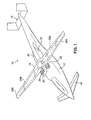
- FIG. 1 is a perspective view of an aircraft 10 having a main airframe 12, a canard assembly 14, a tail assembly 16, a reaction rotor 18, and an engine system 20 that includes a first gas turbine engine 22 and a second gas turbine engine 24.
- the aircraft 10 is a canard rotor wing (CRW) type vehicle capable of operating in a helicopter-type flight mode and a fixed-wing flight mode.
- the reaction rotor 18 can be selectively rotated, for helicopter-type flight, or be rotationally locked, for fixed-wing flight.
- the reaction rotor 18 is aerodynamically shaped to produce desired lift in both flight modes. As shown in FIG. 1, the reaction rotor 18 is rotated to a suitable position to be rotationally locked for substantially horizontal fixed-wing flight.
- the reaction rotor 18 has internal passageways 26A and 26B through which exhaust can selectively flow from the first and second engines 22 and 24 in a helicopter-type flight mode.
- the internal passageways 26A and 26B terminate in outlets 28A and 28B, respectively, located at or near opposite ends of the reaction rotor 18 and oriented in opposite forward/aft directions.
- Fluid i.e., exhaust
- Fluid can flow through the outlets 28A and 28B to produce a combined torsional load on the reaction rotor, which provides rotational power to drive (i.e., to rotate) the reaction rotor 18.
- the engine system 20 further includes a first exhaust nozzle 30 operatively connected to the first engine 22 and a second exhaust nozzle 32 operatively connected to the second engine 24. Fluid (i.e., exhaust) from the first and second engines 22 and 24 can selectively flow through the first and second exhaust nozzles 30 and 32, respectively, in a fixed-wing flight mode.
- the first and second engines 22 and 24 can be any type of suitable gas turbine engines.
- the particular size and configuration of the engines 22 and 24 will vary as desired according to the particular application.
- the first and second engines 22 and 24 will be substantially identical.
- the two flight modes of the aircraft 10 can be understood as follows. Fluid from the first and second engines 22 and 24 can be selectively routed through either the internal passageways 26A and 26B of the reaction rotor 18 or through the first and second exhaust nozzles 30 and 32.
- Fluid from the first and second engines 22 and 24 can be selectively routed through either the internal passageways 26A and 26B of the reaction rotor 18 or through the first and second exhaust nozzles 30 and 32.
- the helicopter-type flight mode fluid is directed from the first and second engines 22 and 24 through the internal passageways 26A and 26B and to the outlets 28A and 28B, in order to drive the reaction rotor 18.
- Rotation of the reaction rotor 18 generates lift, and enables helicopter-type flight, including maneuvers such as vertical takeoffs and landings.
- fluid is directed from the first and second engines 22 and 24 through the first and second exhaust nozzles 30 and 32, respectively, to produce thrust while lift is provided by the rotationally locked reaction rotor 18 (acting as a fixed wing).
- a changeover procedure can be initiated while in flight to transition between the helicopter-type flight mode and the fixed-wing flight mode, or vice-versa.
- the reaction rotor 18 can be locked in place relative to the main airframe 12 to prevent rotation and enable fixed-wing flight.
- the canard assembly 14 provides lift that is useful during the changeover procedure. Further examples of CRW vehicle flight modes are described in U.S. Pat. No. 5,454,530 .
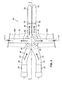
- FIGS. 2 and 3 are schematic representations of the engine system 20.
- FIG. 2 is a schematic top view of the engine system 20, and
- FIG. 3 is a schematic cross-sectional side view of the engine system 20, taken along line 3-3 of FIG. 2.
- the reaction rotor 18 is shown in phantom for reference, but other portions of the aircraft 10 are omitted for clarity.
- the engine system 20 includes a ducting assembly 34 that forms first and second decoupled ducting subassemblies.
- the first ducting subassembly serves the first engine 22 and includes an engine connection portion 36, a rotor connection portion 38 and a nozzle connection portion 40.
- the engine connection portion 36 is operably connected to the first engine 22.
- the rotor connection portion 38 is operably connected to the engine connection portion 36 and the passageway 26A of the reaction rotor 18.
- the nozzle connection portion 40 is operably connected to the first exhaust nozzle 30 and the rotor connection portion 38.
- a first flowpath 42 is defined from the first engine 22 through the engine connection portion 36, rotor connection portion 38 and nozzle connection portion 40.
- the second ducting subassembly serves the second engine 24 and includes an engine connection portion 44, a rotor connection portion 46 and a nozzle connection portion 48.
- the engine connection portion 44 is operably connected to the second engine 24.
- the rotor connection portion 46 is operably connected to the engine connection portion 44 and the passageway 26B of the reaction rotor 18.
- the nozzle connection portion 48 is operably connected to the second exhaust nozzle 32 and the rotor connection portion 46.
- a second flowpath 50 is defined from the second engine 24 through the engine connection portion 44, rotor connection portion 46 and nozzle connection portion 48.
- the rotor connection portions 38 and 46 of the first and second ducting subassemblies are arranged concentrically about an axis A, which is the axis of rotation for the reaction rotor 18.
- the rotor connection portion 46 of the second ducting subassembly defines a generally cylindrical portion of the second flowpath 50
- the rotor connection portion 38 of the first ducting subassembly defines a generally annular portion of the first flowpath 42.
- a first diverter valve 52 is located between the nozzle connection portion 40 of the first ducting subassembly and the first exhaust nozzle 30.
- a second diverter valve 54 is located between the nozzle connection portion 48 of the second ducting subassembly and the second exhaust nozzle 32.
- the first and second diverter valves 52 and 54 operate as selective on/off fluid flow blockers with regard to the first and second flowpaths 42 and 50, respectively.
- the first and second diverter valves 52 and 54 are variable vane assemblies of a type with vanes that rotate like Venetian blinds to selectively permit or deny fluid flow to the respective first and second exhaust nozzles 30 and 32.
- Other types of diverter valves can be utilized in further embodiments.
- the first and second diverter valves 52 and 54 are opened or closed based on the desired flight mode.
- first and second diverter valves 52 and 54 are closed, fluid flow to the first and second exhaust nozzles 30 and 32 is blocked (i.e., denied) and fluid flow is directed through the passageways 26A and 26B of the reaction rotor 18 and out of the outlets 28A and 28B-enabling helicopter-type flight.
- first and second diverter valves 52 and 54 are opened, primary fluid flow is through the first and second exhaust nozzles 30 and 32-enabling fixed-wing flight.
- valves can be used to selectively block fluid flow to the reaction rotor 18 for fixed-wing flight.
- the first and second flowpaths 42 and 50 of the ducting assembly 34 are independent, because the first and second ducting subassemblies are decoupled. That is, fluid flows (i.e., exhaust) from the first and second engines 22 and 24 are independent and decoupled.
- This decoupling provides numerous advantages. For example, engine events relating to one engine do not affect fluid flows relative to the other engine, because the flowpath (or flow circuit) for each engine is self-contained and no flow interaction between the engines is anticipated. One engine can be shut down while the other engine can continue to operate without adverse fluid flow effects.
- the present invention further provides advantages in safety, survivability and installation packaging.
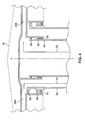
- FIG. 4 is a cross-sectional view of a portion of the engine system 20, taken along line 4-4 of FIG. 2.
- a first bearing set 60 and a second bearing set 62 support the rotor connection portion 46 of the second ducting subassembly relative to the reaction rotor 18 and the passageway 26B.
- the first bearing set 60 is a roller bearing set
- the second bearing set 62 is a ball bearing set (a thrust bearing set).
- a seal 64 is located adjacent to the second bearing set 62 to seal the second flowpath 50 relative to the first flowpath 42.
- a third bearing set 66 and a fourth bearing set 68 support the rotor connection portion 38 of the first ducting subassembly relative to the reaction rotor 18 and the passageway 26A.
- the third bearing set 66 is a roller bearing set
- the fourth bearing set 68 is a ball bearing set (a thrust bearing set).
- a seal 70 is located adjacent to the fourth bearing set 68 to seal the first flowpath 42 relative to environmental air.
- the seals 64 and 70 can both be, for example, conventional brush seals or carbon seals.
Landscapes
- Engineering & Computer Science (AREA)
- Mechanical Engineering (AREA)
- Aviation & Aerospace Engineering (AREA)
- Exhaust Silencers (AREA)
- Supercharger (AREA)
Abstract
Description
- The present invention relates to engine systems, and more particularly to engine systems for aircraft capable of both helicopter-type flight and fixed-wing flight.
- Aircraft are known that enable both helicopter-type flight and fixed-wing flight. One example of such an aircraft is described in
U.S. Pat. No. 5,454,530 . The single-engine X-50 "Dragonfly" aircraft from The Boeing Company, Chicago, IL, is similar to that described inU.S. Pat. No. 5,454,530 . These aircraft are commonly referred to as canard rotor wing (CRW) vehicles. - CRW vehicles include a canard assembly and a reaction rotor. The reaction rotor is driven (i.e., rotated) for relatively low speed helicopter-type flight, which enables maneuvers such as vertical takeoffs and landings. The reaction rotor can be locked in place for higher speed wing-born (fixed-wing) flight, which enables substantially horizontal flight. The canard assembly provides lift that is critical during changeover between helicopter-type flight and fixed-wing flight, and vice-versa.
- However, there are numerous challenges with existing designs. For instance, single-engine designs have limitations with regard to engine placement, maintenance accessibility, etc. Moreover, safety risks are associated with single engine designs, because an engine shutdown event generally has greater safety risks over aircraft having a second engine that can remain operational for partial or emergency flight.
- Known twin-engine designs route engine exhaust flows through common (i.e., coupled) ducting, which presents operational problems. For instance, acoustic coupling of exhaust flows from the engines, which may arise from exhaust flow characteristics and/or minor irregularities (i.e., differences) between adjacent engines, can be communicated through common manifold ducting. Moreover, sudden-onset stall or surge events in one event cannot be adequately compensated for, and can have an undesirable adverse impact on the adjacent engine coupled through common ducting.
- An engine system according to one aspect of the present invention for use with an aircraft capable of operating in a helicopter-type flight mode and a fixed-wing flight mode and is capable of transitioning between those flight modes while in-flight includes first and second engines and a ducting assembly. The ducting assembly includes a first exhaust subassembly in fluid communication with the first engine and a second exhaust subassembly in fluid communication with the second engine. The first exhaust subassembly permits fluid transfer substantially independent of fluid transfer within the second exhaust subassembly.
-
- FIG. 1 is a perspective view of an aircraft having an engine system according to the present invention.
- FIG. 2 is a schematic top view of the engine system.
- FiG. 3 is a schematic cross-sectional side view of the engine system, taken along line 3-3 of FIG. 2.
- FIG. 4 is a cross-sectional view of a portion of the engine system, taken along line 4-4 of FIG. 2.
- FIG. 1 is a perspective view of an
aircraft 10 having amain airframe 12, acanard assembly 14, atail assembly 16, areaction rotor 18, and anengine system 20 that includes a firstgas turbine engine 22 and a secondgas turbine engine 24. Theaircraft 10 is a canard rotor wing (CRW) type vehicle capable of operating in a helicopter-type flight mode and a fixed-wing flight mode. Thereaction rotor 18 can be selectively rotated, for helicopter-type flight, or be rotationally locked, for fixed-wing flight. Thereaction rotor 18 is aerodynamically shaped to produce desired lift in both flight modes. As shown in FIG. 1, thereaction rotor 18 is rotated to a suitable position to be rotationally locked for substantially horizontal fixed-wing flight. - The
reaction rotor 18 hasinternal passageways second engines internal passageways outlets reaction rotor 18 and oriented in opposite forward/aft directions. Fluid (i.e., exhaust) can flow through theoutlets reaction rotor 18. - The
engine system 20 further includes afirst exhaust nozzle 30 operatively connected to thefirst engine 22 and asecond exhaust nozzle 32 operatively connected to thesecond engine 24. Fluid (i.e., exhaust) from the first andsecond engines second exhaust nozzles - The first and
second engines engines second engines - The two flight modes of the
aircraft 10 can be understood as follows. Fluid from the first andsecond engines internal passageways reaction rotor 18 or through the first andsecond exhaust nozzles second engines internal passageways outlets reaction rotor 18. Rotation of thereaction rotor 18 generates lift, and enables helicopter-type flight, including maneuvers such as vertical takeoffs and landings. In the fixed-wing flight mode, fluid is directed from the first andsecond engines second exhaust nozzles - A changeover procedure can be initiated while in flight to transition between the helicopter-type flight mode and the fixed-wing flight mode, or vice-versa. As desired by a pilot during flight, the
reaction rotor 18 can be locked in place relative to themain airframe 12 to prevent rotation and enable fixed-wing flight. Thecanard assembly 14 provides lift that is useful during the changeover procedure. Further examples of CRW vehicle flight modes are described inU.S. Pat. No. 5,454,530 . - FIGS. 2 and 3 are schematic representations of the
engine system 20. FIG. 2 is a schematic top view of theengine system 20, and FIG. 3 is a schematic cross-sectional side view of theengine system 20, taken along line 3-3 of FIG. 2. Thereaction rotor 18 is shown in phantom for reference, but other portions of theaircraft 10 are omitted for clarity. - The
engine system 20 includes aducting assembly 34 that forms first and second decoupled ducting subassemblies. The first ducting subassembly serves thefirst engine 22 and includes anengine connection portion 36, arotor connection portion 38 and anozzle connection portion 40. Theengine connection portion 36 is operably connected to thefirst engine 22. Therotor connection portion 38 is operably connected to theengine connection portion 36 and thepassageway 26A of thereaction rotor 18. Thenozzle connection portion 40 is operably connected to thefirst exhaust nozzle 30 and therotor connection portion 38. Afirst flowpath 42 is defined from thefirst engine 22 through theengine connection portion 36,rotor connection portion 38 andnozzle connection portion 40. The second ducting subassembly serves thesecond engine 24 and includes anengine connection portion 44, arotor connection portion 46 and anozzle connection portion 48. Theengine connection portion 44 is operably connected to thesecond engine 24. Therotor connection portion 46 is operably connected to theengine connection portion 44 and thepassageway 26B of thereaction rotor 18. Thenozzle connection portion 48 is operably connected to thesecond exhaust nozzle 32 and therotor connection portion 46. Asecond flowpath 50 is defined from thesecond engine 24 through theengine connection portion 44,rotor connection portion 46 andnozzle connection portion 48. - As shown in FIG. 3, the
rotor connection portions reaction rotor 18. In that way, therotor connection portion 46 of the second ducting subassembly defines a generally cylindrical portion of thesecond flowpath 50, and therotor connection portion 38 of the first ducting subassembly defines a generally annular portion of thefirst flowpath 42. - A
first diverter valve 52 is located between thenozzle connection portion 40 of the first ducting subassembly and thefirst exhaust nozzle 30. Asecond diverter valve 54 is located between thenozzle connection portion 48 of the second ducting subassembly and thesecond exhaust nozzle 32. The first andsecond diverter valves second diverter valves second exhaust nozzles - The first and
second diverter valves second diverter valves second exhaust nozzles passageways reaction rotor 18 and out of theoutlets second diverter valves second exhaust nozzles 30 and 32-enabling fixed-wing flight. It should be noted that when the first andsecond diverter valves passageways reaction rotor 18, but fluid will naturally tend to flow substantially through the first andsecond exhaust nozzles reaction rotor 18 for fixed-wing flight. - The first and second flowpaths 42 and 50 of the
ducting assembly 34 are independent, because the first and second ducting subassemblies are decoupled. That is, fluid flows (i.e., exhaust) from the first andsecond engines - FIG. 4 is a cross-sectional view of a portion of the
engine system 20, taken along line 4-4 of FIG. 2. As shown in FIG. 4, a first bearing set 60 and a second bearing set 62 support therotor connection portion 46 of the second ducting subassembly relative to thereaction rotor 18 and thepassageway 26B. The first bearing set 60 is a roller bearing set, and the second bearing set 62 is a ball bearing set (a thrust bearing set). Aseal 64 is located adjacent to the second bearing set 62 to seal thesecond flowpath 50 relative to thefirst flowpath 42. - A third bearing set 66 and a fourth bearing set 68 support the
rotor connection portion 38 of the first ducting subassembly relative to thereaction rotor 18 and thepassageway 26A. The third bearing set 66 is a roller bearing set, and the fourth bearing set 68 is a ball bearing set (a thrust bearing set). Aseal 70 is located adjacent to the fourth bearing set 68 to seal thefirst flowpath 42 relative to environmental air. Theseals - It should be noted that the arrangement of the bearings and the interface between the rotating components of the
ducting assembly 34 can vary as desired for a particular application. The particular embodiment shown in FIG. 4 is presented by way of example, and not by way of limitation. - Although the present invention has been described with reference to preferred embodiments, workers skilled in the art will recognize that changes may be made in form and detail without departing from the scope of the invention. For instance, the particular size, shape and arrangement of the flowpaths of the decoupled ducting can vary as desired, and two or more independent flowpaths can be created, depending on the number of engines utilized with a particular aircraft.
Claims (12)
- An engine system (20) for an aircraft (10) capable of both a helicopter-type flight mode and a fixed-wing flight mode and being able to transition between flight modes during flight, the engine system comprising:a first engine (22);a second engine (24);a reaction rotor (18) having a first supply duct (26A) and a second supply duct (26B) extending therethrough;a first exhaust nozzle (30);a second exhaust nozzle (32); anda flow transfer duct (34) defining a first flow path (42) and a second flow path (50), wherein the first flowpath (42) of the flow transfer duct is in fluid communication with the first engine (22), the first supply duct (28A) of the reaction rotor (18) and the first exhaust nozzle (30), and wherein the second flowpath (50) of the flow transfer duct is in fluid communication with the second engine (24), the second supply duct (28B) of the reaction rotor (18) and the second exhaust nozzle (32).
- The engine system of claim 1, wherein both the first engine (22) and the second (24) engine are gas turbine engines.
- The engine system of claim 1 or 2, wherein the first flow path (42) and the second flow path (50) are arranged concentrically.
- The engine system of claim 3, wherein the second flow path (50) is located inside the first flow path (42).
- The engine system of any preceding claim and further comprising:a first diverter valve (52) operable to permit closure of a portion of the first exhaust nozzle (30); anda second diverter valve (54) operable to permit closure of a portion of the second exhaust nozzle (32).
- An engine system (20) for an aircraft (10) having a reaction rotor (18) and being capable of both helicopter-type flight and fixed-wing flight, the engine system (10) comprising:a first turboengine (22);a second turboengine (24);a first exhaust subassembly in fluid communication with the first turboengine (22) and a first transfer duct (28A) located on or within the reaction rotor (18); anda second exhaust subassembly in fluid communication with the second turboengine (24) and a second transfer duct (28B) located on or within the reaction rotor (18), wherein fluid transfer through the first exhaust subassembly is substantially independent of fluid transfer through the second exhaust subassembly.
- The engine system of claim 6 and further comprising:a first diverter valve (52) operably connected to the first exhaust subassembly for selectively directing fluid flow within the first exhaust subassembly.
- The engine system of claim 6 or 7 and further comprising:a second diverter valve (54) operably connected to the second exhaust subassembly for selectively directing fluid flow within the second exhaust subassembly.
- An engine system (20) for an aircraft (10) having a canard wing assembly (14) and a reaction rotor assembly (18), wherein the aircraft (10) is capable of operating in a helicopter-type flight mode and a fixed-wing flight mode and is capable of transitioning between those flight modes while in-flight, the engine system comprising:a first engine (22);a second engine (24);a ducting assembly (34) having a first exhaust subassembly in fluid communication with the first engine (22) and a second exhaust subassembly in fluid communication with the second engine (24), wherein the first exhaust subassembly permits fluid transfer substantially independent of fluid transfer within the second exhaust subassembly.
- The engine system of claim 9, wherein the ducting assembly (34) is configured to permit selective fluid transfer from the first engine (22) to the reaction rotor assembly (18) for aircraft operation in the helicopter-type flight mode or to a first exhaust nozzle (30) for aircraft operation in the fixed-wing flight mode.
- The engine system of claim 9 or 10, wherein the ducting assembly (34) is configured to permit selective fluid transfer from the second engine (24) to the reaction rotor assembly (18) for aircraft operation in the helicopter-type flight mode or to a second exhaust nozzle (32) for aircraft operation in the fixed-wing flight mode.
- The engine system of claim 9, 10 or 11, wherein both the first engine (22) and the second engine (24) are gas turbine engines.
Applications Claiming Priority (1)
| Application Number | Priority Date | Filing Date | Title |
|---|---|---|---|
| US11/471,183 US7624942B2 (en) | 2006-06-20 | 2006-06-20 | Decoupled ducting for twin-engine reaction rotor drive |
Publications (2)
| Publication Number | Publication Date |
|---|---|
| EP1870332A1 true EP1870332A1 (en) | 2007-12-26 |
| EP1870332B1 EP1870332B1 (en) | 2010-01-27 |
Family
ID=38461802
Family Applications (1)
| Application Number | Title | Priority Date | Filing Date |
|---|---|---|---|
| EP07252470A Not-in-force EP1870332B1 (en) | 2006-06-20 | 2007-06-18 | Decoupled ducting for twin-engine reaction rotor drive |
Country Status (4)
| Country | Link |
|---|---|
| US (1) | US7624942B2 (en) |
| EP (1) | EP1870332B1 (en) |
| JP (1) | JP2008002459A (en) |
| DE (1) | DE602007004531D1 (en) |
Cited By (1)
| Publication number | Priority date | Publication date | Assignee | Title |
|---|---|---|---|---|
| EP1936173A3 (en) * | 2006-12-13 | 2013-12-18 | General Electric Company | Engine propulsion system having first and second exhaust ducts |
Families Citing this family (12)
| Publication number | Priority date | Publication date | Assignee | Title |
|---|---|---|---|---|
| MC200107A1 (en) * | 2007-07-24 | 2008-02-13 | Jean-Claude Tourn | Aerial device |
| US8931728B1 (en) * | 2010-09-09 | 2015-01-13 | Groen Brothers Aviation, Inc. | Fail safe, multiple source, tip-jet supply apparatus and method |
| EP2899118B1 (en) | 2014-01-27 | 2019-01-16 | AIRBUS HELICOPTERS DEUTSCHLAND GmbH | Rotorcraft with a fuselage and at least one main rotor |
| MC200172B1 (en) * | 2015-02-13 | 2016-04-15 | Tourn Jean Claude | AERIAL DEVICE COMPRISING A CARRIER STRUCTURE AND A ROTATING ELEMENT HAVING FASTENING MEANS FOR ATTACHING AT LEAST ONE BLADE |
| USD950469S1 (en) * | 2020-03-27 | 2022-05-03 | Aerion Intellectual Property Management Corporation | Airplane |
| USD950465S1 (en) * | 2020-03-27 | 2022-05-03 | Aerion Intellectual Property Management Corporation | Airplane |
| USD950470S1 (en) * | 2020-03-27 | 2022-05-03 | Aerion Intellectual Property Management Corporation | Airplane |
| USD950466S1 (en) * | 2020-03-27 | 2022-05-03 | Aerion Intellectual Property Management Corporation | Airplane |
| USD950467S1 (en) * | 2020-03-27 | 2022-05-03 | Aerion Intellectual Property Management Corporation | Airplane |
| USD950468S1 (en) * | 2020-03-27 | 2022-05-03 | Aerion Intellectual Property Management Corporation | Airplane |
| USD1041386S1 (en) * | 2021-05-18 | 2024-09-10 | Leonardo S.P.A. | Helicopter toy |
| USD1040728S1 (en) * | 2021-05-18 | 2024-09-03 | Leonardo S.P.A. | Helicopter |
Citations (1)
| Publication number | Priority date | Publication date | Assignee | Title |
|---|---|---|---|---|
| US3792827A (en) * | 1972-11-10 | 1974-02-19 | Teledyne Ryan Aeronautical Inc | Vtol aircraft with cruciform rotor wing |
Family Cites Families (4)
| Publication number | Priority date | Publication date | Assignee | Title |
|---|---|---|---|---|
| US5454530A (en) | 1993-05-28 | 1995-10-03 | Mcdonnell Douglas Helicopter Company | Canard rotor/wing |
| US7014142B2 (en) * | 2004-02-03 | 2006-03-21 | The Boeing Company | Low-drag rotor/wing flap |
| US7275711B1 (en) * | 2004-02-23 | 2007-10-02 | Kenneth Warren Flanigan | Gas-powered tip-jet-driven compound VTOL aircraft |
| US7412825B2 (en) * | 2005-10-06 | 2008-08-19 | The Boeing Company | Flow path splitter duct |
-
2006
- 2006-06-20 US US11/471,183 patent/US7624942B2/en active Active
-
2007
- 2007-05-22 JP JP2007134862A patent/JP2008002459A/en active Pending
- 2007-06-18 EP EP07252470A patent/EP1870332B1/en not_active Not-in-force
- 2007-06-18 DE DE602007004531T patent/DE602007004531D1/en active Active
Patent Citations (1)
| Publication number | Priority date | Publication date | Assignee | Title |
|---|---|---|---|---|
| US3792827A (en) * | 1972-11-10 | 1974-02-19 | Teledyne Ryan Aeronautical Inc | Vtol aircraft with cruciform rotor wing |
Cited By (1)
| Publication number | Priority date | Publication date | Assignee | Title |
|---|---|---|---|---|
| EP1936173A3 (en) * | 2006-12-13 | 2013-12-18 | General Electric Company | Engine propulsion system having first and second exhaust ducts |
Also Published As
| Publication number | Publication date |
|---|---|
| US20070290099A1 (en) | 2007-12-20 |
| JP2008002459A (en) | 2008-01-10 |
| DE602007004531D1 (en) | 2010-03-18 |
| US7624942B2 (en) | 2009-12-01 |
| EP1870332B1 (en) | 2010-01-27 |
Similar Documents
| Publication | Publication Date | Title |
|---|---|---|
| EP1870332B1 (en) | Decoupled ducting for twin-engine reaction rotor drive | |
| US11492099B2 (en) | Aircraft nacelle having electric motor and thrust reversing air exhaust flaps | |
| EP3421366B1 (en) | Hybrid electric propulsion system for an aircraft | |
| EP3659908B1 (en) | Propulsion engine thermal management system | |
| EP2868580B1 (en) | Inlet system for a precooler | |
| EP2399018B1 (en) | Air vehicle propusion system with counter rotating fan design and method for noise reduction | |
| EP1243782B2 (en) | Double jet engine inlet | |
| US20230021836A1 (en) | Unducted thrust producing system | |
| EP2868581B1 (en) | Inlet system having dual inlets | |
| US20080010969A1 (en) | Gas turbine engine and method of operating same | |
| US9994330B2 (en) | Aircraft | |
| EP2932068B1 (en) | Gas turbine engine with cooling scheme for drive gear system and pitch control | |
| US11629651B2 (en) | Gas turbine engine having a turbomachine and an electric motor coupled to a propeller | |
| EP1918560B1 (en) | Combined control for supplying cooling air and support air in a turbine engine nozzle | |
| US20150096627A1 (en) | Engine mounted inlet plenum for a rotorcraft | |
| CA2605518C (en) | Engine propulsion system and methods of assembling the same | |
| US7412825B2 (en) | Flow path splitter duct | |
| US12595066B1 (en) | Blended wing aircraft | |
| US12320313B2 (en) | Vectoring exhaust nozzle for an aircraft powerplant | |
| US20250368315A1 (en) | Engine pylon assembly with a control surface for an aircraft | |
| US11867135B1 (en) | Vectoring exhaust nozzle for an aircraft powerplant | |
| US20260077855A1 (en) | Aircraft having a propulsion system | |
| EP3992086B1 (en) | Aircraft and method of operating same |
Legal Events
| Date | Code | Title | Description |
|---|---|---|---|
| PUAI | Public reference made under article 153(3) epc to a published international application that has entered the european phase |
Free format text: ORIGINAL CODE: 0009012 |
|
| AK | Designated contracting states |
Kind code of ref document: A1 Designated state(s): AT BE BG CH CY CZ DE DK EE ES FI FR GB GR HU IE IS IT LI LT LU LV MC MT NL PL PT RO SE SI SK TR |
|
| AX | Request for extension of the european patent |
Extension state: AL BA HR MK YU |
|
| 17P | Request for examination filed |
Effective date: 20071227 |
|
| 17Q | First examination report despatched |
Effective date: 20080205 |
|
| AKX | Designation fees paid |
Designated state(s): DE FR GB |
|
| GRAP | Despatch of communication of intention to grant a patent |
Free format text: ORIGINAL CODE: EPIDOSNIGR1 |
|
| GRAS | Grant fee paid |
Free format text: ORIGINAL CODE: EPIDOSNIGR3 |
|
| GRAA | (expected) grant |
Free format text: ORIGINAL CODE: 0009210 |
|
| AK | Designated contracting states |
Kind code of ref document: B1 Designated state(s): DE FR GB |
|
| REG | Reference to a national code |
Ref country code: GB Ref legal event code: FG4D |
|
| REF | Corresponds to: |
Ref document number: 602007004531 Country of ref document: DE Date of ref document: 20100318 Kind code of ref document: P |
|
| PGFP | Annual fee paid to national office [announced via postgrant information from national office to epo] |
Ref country code: FR Payment date: 20100709 Year of fee payment: 4 |
|
| PLBE | No opposition filed within time limit |
Free format text: ORIGINAL CODE: 0009261 |
|
| STAA | Information on the status of an ep patent application or granted ep patent |
Free format text: STATUS: NO OPPOSITION FILED WITHIN TIME LIMIT |
|
| 26N | No opposition filed |
Effective date: 20101028 |
|
| REG | Reference to a national code |
Ref country code: FR Ref legal event code: ST Effective date: 20120229 |
|
| PG25 | Lapsed in a contracting state [announced via postgrant information from national office to epo] |
Ref country code: FR Free format text: LAPSE BECAUSE OF NON-PAYMENT OF DUE FEES Effective date: 20110630 |
|
| PGFP | Annual fee paid to national office [announced via postgrant information from national office to epo] |
Ref country code: DE Payment date: 20120613 Year of fee payment: 6 |
|
| PGFP | Annual fee paid to national office [announced via postgrant information from national office to epo] |
Ref country code: GB Payment date: 20120613 Year of fee payment: 6 |
|
| GBPC | Gb: european patent ceased through non-payment of renewal fee |
Effective date: 20130618 |
|
| REG | Reference to a national code |
Ref country code: DE Ref legal event code: R119 Ref document number: 602007004531 Country of ref document: DE Effective date: 20140101 |
|
| PG25 | Lapsed in a contracting state [announced via postgrant information from national office to epo] |
Ref country code: GB Free format text: LAPSE BECAUSE OF NON-PAYMENT OF DUE FEES Effective date: 20130618 Ref country code: DE Free format text: LAPSE BECAUSE OF NON-PAYMENT OF DUE FEES Effective date: 20140101 |