EP1870320A2 - System for completely closing the space between the cab and semi-trailer of an industrial or commercial vehicle, to improve the aerodynamics of the vehicle - Google Patents
System for completely closing the space between the cab and semi-trailer of an industrial or commercial vehicle, to improve the aerodynamics of the vehicle Download PDFInfo
- Publication number
- EP1870320A2 EP1870320A2 EP07110560A EP07110560A EP1870320A2 EP 1870320 A2 EP1870320 A2 EP 1870320A2 EP 07110560 A EP07110560 A EP 07110560A EP 07110560 A EP07110560 A EP 07110560A EP 1870320 A2 EP1870320 A2 EP 1870320A2
- Authority
- EP
- European Patent Office
- Prior art keywords
- inflatable
- semi
- spoilers
- trailer
- rigid
- Prior art date
- Legal status (The legal status is an assumption and is not a legal conclusion. Google has not performed a legal analysis and makes no representation as to the accuracy of the status listed.)
- Granted
Links
Images


Classifications
-
- B—PERFORMING OPERATIONS; TRANSPORTING
- B62—LAND VEHICLES FOR TRAVELLING OTHERWISE THAN ON RAILS
- B62D—MOTOR VEHICLES; TRAILERS
- B62D35/00—Vehicle bodies characterised by streamlining
- B62D35/001—For commercial vehicles or tractor-trailer combinations, e.g. caravans
- B62D35/004—Inflatable nose or rear cones
-
- B—PERFORMING OPERATIONS; TRANSPORTING
- B62—LAND VEHICLES FOR TRAVELLING OTHERWISE THAN ON RAILS
- B62D—MOTOR VEHICLES; TRAILERS
- B62D35/00—Vehicle bodies characterised by streamlining
- B62D35/001—For commercial vehicles or tractor-trailer combinations, e.g. caravans
Definitions
- the present invention relates to a system for completely closing the space between the cab and semi-trailer of an industrial or commercial vehicle, to improve the aerodynamics of the vehicle.
- the energy efficiency of motor vehicles is known to be directly related to the aerodynamic drag and turbulence caused by the motion of the vehicle.
- One solution of these consists in mounting an air deflector on the roof of the cab, to redirect the air, at least partially, over the top of the trailer, which is usually higher than the cab. This prevents the air from breaking on the forward face of the trailer.
- Another solution consists of attaching rigid spoilers to both sides and the top of the rear profile of the cab.
- the purpose of the present invention is to solve the problems described above with a system for completely closing the space between the cab and semi-trailer of an industrial or commercial vehicle, to improve the aerodynamics of the vehicle.
- the space between the tractor cab and semi-trailer is closed by means of dynamic inflatable and retractable extensions (referred to hereafter as "inflatable spoilers"). Due to their particular geometric conformation and the material used, the inflatable spoilers dynamically adjust to the profile of the semi-trailer, during vehicle manoeuvring or more generally in conditions of relative motion between said tractor and semi-trailer.
- inflatable spoilers dynamic inflatable and retractable extensions
- the present invention relates to a system for completely closing the space between the cab and semi-trailer of an industrial or commercial vehicle, comprising rigid spoilers attached to the side and top edges of the rear of the cab, characterized in that it also comprises inflatable and retractable spoilers, attached to said rigid spoilers as dynamic extensions thereof, and suitable to extend so as to adhere to the front wall of the semi-trailer and completely close the space between the cab and semi-trailer.
- system also comprises a rounded abutment surface as an extension of the front wall of the semi-trailer, suitable for facilitating the contact with said inflatable spoilers.
- the inflatable spoilers close the space between the cab and semi-trailer dynamically, so as to adapt to the vibrations and to the relative movements, which may even be rapid, when the vehicle is travelling.
- They are preferably divided into three parts, a top part and two side parts, also to enable at least one of the two side parts to be opened to allow access to the space between the cab and semi-trailer.
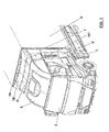
- FIG. 1 show partial views of a tractor 1, with relative cab 2.
- an air deflector 3 is mounted on the roof of the cab, but this part may not be present, depending on the specific type of tractor.
- Rigid spoilers 5 are attached directly to the rear part 4 of the cab, around the side and top edges of the rear of said cab and of the deflector 3, where present.
- the rigid spoilers 5 are divided into three parts, along the dividing lines 7: a top part 5', fitted around the deflector 3, if present, or the roof of the cab, and two side parts 5" on the two sides of the cab. At least one of these side parts 5" can be mounted by hinges to the cab so that it can be opened like a door to allow access to the space between the cab 2 and semi-trailer 6.
- the rigid spoilers 5 extend towards the semi-trailer 6 for a given width, so as to leave a free gap.
- Inflatable spoilers 10 are attached to the rigid spoilers 5, said inflatable spoilers 10 also being divided into three parts, along the same division lines 7 of the rigid spoilers: a top part 10' which is an extension of the top part 5' of the rigid spoiler, and two side parts 10" which are extensions of the side parts 5" of the rigid spoiler.
- a top part 10' which is an extension of the top part 5' of the rigid spoiler
- two side parts 10" which are extensions of the side parts 5" of the rigid spoiler.
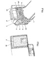
- the inflatable spoilers 10 comprise a rigid internal support 11, made, for instance, of aluminium, which also acts as a container for the inflatable spoiler 10 when the latter is deflated and retracted.
- the internal support 11 is attached to the rigid spoiler 5 by means of metal side brackets 12.
- the internal support 11 extends in a direction that is essentially perpendicular to that of the rigid spoilers 5.
- the cross-section of the inflatable spoiler 10 corresponds to a given width of the internal support 11, growing thinner until shaping to a point 13 towards the outer edge facing the semi-trailer 6, thus assuming a triangle-like shape.
- the profile of the surface of the front wall of the semi-trailer 6 may be provided with an extension in the form of a rounded abutment surface 15, comprising rigid front adapters, for instance made of plastic, for example semi-cylindrical in shape.
- said rounded surface need not necessarily be present.
- the rounded abutment surface 15 is suitable to allow a correct contact with the edge 13 of the inflatable spoilers 10.
- the latter can adapt to different types of semi-trailers, whether provided with a front adapter or not. This characteristic is useful, for example, for optimizing fleet management, when one tractor can be used with different semi-trailers.
- the inflatable spoilers 10 comprise a non-rigid, inflatable and retractable part, for example made of PVC sheet, with a smooth outer surface facing the outside of the vehicle to improve the aerodynamic efficiency of the vehicle.
- a non-rigid, inflatable and retractable part for example made of PVC sheet
- the required geometry of the spoiler is maintained by means of internal sector cross-pieces 20.
- a series of heat-sealed flaps 21 are attached transversely to the inside edges of the non-rigid part, said flaps possibly being made of the same material as said non-rigid part.
- Respective series of cross-pieces 20, made of a less rigid and thinner material than the outer surfaces, are stitched transversely to these flaps 21, so as to facilitate retraction and folding when the inflatable spoilers 10 are deflated.
- the inflatable spoilers are operated by means of an inflating and packing/retracting system that must guarantee continuous (re)inflation and (re)deflation so that when the inflatable structure extends it comes into contact with the semi-trailer 6, and with the front adapter 15 if present, in the correct position, so as to fit properly and not "stick” in an wrong position.
- tie elements 22 are attached to the outer and inner surfaces of the sides of the inflatable spoilers, said tie elements being operated in a suitable way and acting, starting from the end 13 of the spoiler, to pull it back and fold it closed, and re-open it in a perpendicular direction, forcing it into the desired geometry when inflated.
- the method of inflation can use a system known in the prior art, for example comprising ordinary pumps that inflate and deflate the inflatable spoilers, governed by a control system that also controls the stays on the side surfaces of the inflatable spoilers.
- the spoilers are inflated at a pressure sufficiently higher than the atmospheric pressure, so as to remain in the extended condition. They are deflated at a pressure lower than the atmospheric pressure and maintained in this condition, so as to remain folded on the internal supports 11, occupying as little space as possible.
Landscapes
- Engineering & Computer Science (AREA)
- Chemical & Material Sciences (AREA)
- Combustion & Propulsion (AREA)
- Transportation (AREA)
- Mechanical Engineering (AREA)
- Body Structure For Vehicles (AREA)
- Forklifts And Lifting Vehicles (AREA)
- Air Bags (AREA)
Abstract
Description
- The present invention relates to a system for completely closing the space between the cab and semi-trailer of an industrial or commercial vehicle, to improve the aerodynamics of the vehicle.
- The energy efficiency of motor vehicles is known to be directly related to the aerodynamic drag and turbulence caused by the motion of the vehicle.
- Efficiency in fuel consumption has become a paramount concern in view of increasing fuel costs and overall fuel usage, also due to problems associated with pollution.
- These requirements are even more important in the case of large vehicles, such as industrial and commercial vehicles. The aerodynamic performance of the majority of these vehicles is reduced due to their overall shape, for instance the flat-faced frontal area of the cab, or the parts of the trailer, or semi-trailer, in case of articulated vehicles, which are square.
- As the vehicle moves, a significant amount of air turbulence is produced, especially to the rear of the vehicle, which results in increased aerodynamic drag and leads to higher fuel consumption. This phenomenon increases in proportion to the speed of the vehicle, reaching particularly high levels on roads where vehicles can travel at high speeds, such as motorways.
- The reduced aerodynamic efficiency of these vehicles is partly due to the fact that air flows through the space between the cab and semi-trailer, in case of articulated vehicles. This airflow is in opposition to the correct airflow, which should go over the outer surface of the vehicle.
- Solutions aimed at solving this problem are known in the prior art.
- One solution of these consists in mounting an air deflector on the roof of the cab, to redirect the air, at least partially, over the top of the trailer, which is usually higher than the cab. This prevents the air from breaking on the forward face of the trailer.
- Another solution consists of attaching rigid spoilers to both sides and the top of the rear profile of the cab.
- However, these systems only partially solve the problem of reducing aerodynamic drag, in that the air can still flow through the space between the cab and trailer.
- Therefore the purpose of the present invention is to solve the problems described above with a system for completely closing the space between the cab and semi-trailer of an industrial or commercial vehicle, to improve the aerodynamics of the vehicle.
- According to the main embodiments of the present invention, the space between the tractor cab and semi-trailer is closed by means of dynamic inflatable and retractable extensions (referred to hereafter as "inflatable spoilers"). Due to their particular geometric conformation and the material used, the inflatable spoilers dynamically adjust to the profile of the semi-trailer, during vehicle manoeuvring or more generally in conditions of relative motion between said tractor and semi-trailer.
- This solution eliminates the contribution to aerodynamic drag generated by that portion of the airflow that would otherwise circulate in the space between the cab and semi-trailer. It should also be noted that this contribution is particularly significant in case of side winds, a condition that is statistically highly probable.
- The present invention relates to a system for completely closing the space between the cab and semi-trailer of an industrial or commercial vehicle, comprising rigid spoilers attached to the side and top edges of the rear of the cab, characterized in that it also comprises inflatable and retractable spoilers, attached to said rigid spoilers as dynamic extensions thereof, and suitable to extend so as to adhere to the front wall of the semi-trailer and completely close the space between the cab and semi-trailer.
- According to an alternative embodiment the system also comprises a rounded abutment surface as an extension of the front wall of the semi-trailer, suitable for facilitating the contact with said inflatable spoilers.
- It is particular object of the present invention, a system for completely closing the space between the cab and semi-trailer of an industrial or commercial vehicle, to improve the aerodynamics of the vehicle, as better described in the claims, which are an integral part of this description.
- Further purposes and advantages of this invention will become clear from the following detailed description of a preferred embodiment (and the relative alternative embodiments), and the drawings that are attached hereto, which are merely illustrative and not limitative, in which:
- figure 1 is a cutaway view of a vehicle comprising the system according to the present invention;
- figure 2 is a cutaway view of the part of the system attached to the vehicle cab;
- figure 3 is a cutaway view of the part of the system attached to the semi-trailer of the vehicle;
- figures 4 to 7 are views from different perspectives of the system according to the invention;
- figures 8 and 9 are, respectively, longitudinal and cross-sections of the inflatable spoiler part.
- In the drawings the same reference numbers and letters are used to indicate the same parts or components.
- According to the invention, the inflatable spoilers close the space between the cab and semi-trailer dynamically, so as to adapt to the vibrations and to the relative movements, which may even be rapid, when the vehicle is travelling.
- They are preferably divided into three parts, a top part and two side parts, also to enable at least one of the two side parts to be opened to allow access to the space between the cab and semi-trailer.
- The invention is now described with reference to the non-limiting example illustrated in the drawings.
- The drawings show partial views of a tractor 1, with
relative cab 2. In the non-limiting example described here, an air deflector 3 is mounted on the roof of the cab, but this part may not be present, depending on the specific type of tractor. -
Rigid spoilers 5 are attached directly to therear part 4 of the cab, around the side and top edges of the rear of said cab and of the deflector 3, where present. Therigid spoilers 5 are divided into three parts, along the dividing lines 7: a top part 5', fitted around the deflector 3, if present, or the roof of the cab, and twoside parts 5" on the two sides of the cab. At least one of theseside parts 5" can be mounted by hinges to the cab so that it can be opened like a door to allow access to the space between thecab 2 andsemi-trailer 6. - The
rigid spoilers 5 extend towards thesemi-trailer 6 for a given width, so as to leave a free gap. -
Inflatable spoilers 10 are attached to therigid spoilers 5, saidinflatable spoilers 10 also being divided into three parts, along thesame division lines 7 of the rigid spoilers: a top part 10' which is an extension of the top part 5' of the rigid spoiler, and twoside parts 10" which are extensions of theside parts 5" of the rigid spoiler. Thus at least one of the twoside parts 10" of the inflatable spoilers can be opened together with thecorresponding part 5" of the rigid spoiler, since it is integral therewith. - The
inflatable spoilers 10 comprise a rigidinternal support 11, made, for instance, of aluminium, which also acts as a container for theinflatable spoiler 10 when the latter is deflated and retracted. Theinternal support 11 is attached to therigid spoiler 5 by means ofmetal side brackets 12. Theinternal support 11 extends in a direction that is essentially perpendicular to that of therigid spoilers 5. - In general the cross-section of the
inflatable spoiler 10 corresponds to a given width of theinternal support 11, growing thinner until shaping to apoint 13 towards the outer edge facing the semi-trailer 6, thus assuming a triangle-like shape. - The profile of the surface of the front wall of the semi-trailer 6 may be provided with an extension in the form of a
rounded abutment surface 15, comprising rigid front adapters, for instance made of plastic, for example semi-cylindrical in shape. However, said rounded surface need not necessarily be present. - The
rounded abutment surface 15 is suitable to allow a correct contact with theedge 13 of theinflatable spoilers 10. However the latter can adapt to different types of semi-trailers, whether provided with a front adapter or not. This characteristic is useful, for example, for optimizing fleet management, when one tractor can be used with different semi-trailers. - The
inflatable spoilers 10 comprise a non-rigid, inflatable and retractable part, for example made of PVC sheet, with a smooth outer surface facing the outside of the vehicle to improve the aerodynamic efficiency of the vehicle. When inflated, the required geometry of the spoiler is maintained by means ofinternal sector cross-pieces 20. More specifically, a series of heat-sealedflaps 21 are attached transversely to the inside edges of the non-rigid part, said flaps possibly being made of the same material as said non-rigid part. Respective series ofcross-pieces 20, made of a less rigid and thinner material than the outer surfaces, are stitched transversely to theseflaps 21, so as to facilitate retraction and folding when theinflatable spoilers 10 are deflated. - The inflatable spoilers are operated by means of an inflating and packing/retracting system that must guarantee continuous (re)inflation and (re)deflation so that when the inflatable structure extends it comes into contact with the
semi-trailer 6, and with thefront adapter 15 if present, in the correct position, so as to fit properly and not "stick" in an wrong position. - For this purpose a series of
tie elements 22 are attached to the outer and inner surfaces of the sides of the inflatable spoilers, said tie elements being operated in a suitable way and acting, starting from theend 13 of the spoiler, to pull it back and fold it closed, and re-open it in a perpendicular direction, forcing it into the desired geometry when inflated. - The method of inflation can use a system known in the prior art, for example comprising ordinary pumps that inflate and deflate the inflatable spoilers, governed by a control system that also controls the stays on the side surfaces of the inflatable spoilers.
- The spoilers are inflated at a pressure sufficiently higher than the atmospheric pressure, so as to remain in the extended condition. They are deflated at a pressure lower than the atmospheric pressure and maintained in this condition, so as to remain folded on the
internal supports 11, occupying as little space as possible. - It will be apparent to the person skilled in the art that other alternative and equivalent embodiments of the invention can be conceived and reduced to practice without departing from the true spirit of the invention.
- From the description set forth above it will be possible for the person skilled in the art to embody the invention without introducing any further construction details.
Claims (9)
- System for completely closing the space between the cab and semi-trailer of an industrial or commercial vehicle, comprising rigid spoilers (5) attached to the side and top edges of the rear of the cab,
characterized in that it also comprises
inflatable and retractable spoilers (10), attached to said rigid spoilers (5) as dynamic extensions thereof, and suitable to extend so as to adhere to the front wall (4, 15) of the semi-trailer and completely close the space between the cab and semi-trailer. - System according to claim 1, characterized in that it also comprises a rounded abutment surface (15) as an extension of said front wall (4) of the semi-trailer, suitable to facilitate the contact with said inflatable spoilers (10).
- System according to claim 2, characterized in that said rounded abutment surface (15) comprises rigid front adapters, for instance made of plastic and for example semi-cylindrical in shape.
- System according to claim 1, characterized in that said rigid spoilers (5) and said inflatable spoilers (10) are divided into a top part (5', 10') and two side parts (5", 10"), at least one of said side parts being adapted to be opened.
- System according to claim 1, characterized in that said inflatable spoilers (10) comprise:- a rigid internal support (11) attached to said rigid spoiler (5), and extending in a direction that is essentially perpendicular to said rigid spoiler;- an inflatable and retractable part (10, 13, 20, 21, 22), attached to said internal support (11), said internal support being suitable to essentially contain said inflatable and retractable part when retracted, said inflatable and retractable part, when extended, having a pointed end (13) that comes into contact with said front wall (4, 15) of the semi-trailer.
- System according to claim 5, characterized in that said inflatable and retractable part is internally provided with sector cross-pieces (20), attached transversely to the inside edges of said inflatable part, suitable to maintain said inflatable part in the desired shape when extended.
- System according to claim 6, characterized in that said sector cross-pieces (20) are attached to the inside edges of said inflatable part by means of flaps (21) that are heat-sealed to said inside edges, said sector cross-pieces (20) being stitched to said flaps (21).
- System according to claim 5, characterized in that said internal support (11) is attached to said rigid spoiler (5) by means of metal side brackets (12).
- System according to claim 5, characterized in that said inflatable and retractable part is made of PVC sheet, the outer surface of which facing the outside of the vehicle is smooth.
Applications Claiming Priority (1)
| Application Number | Priority Date | Filing Date | Title |
|---|---|---|---|
| IT001177A ITMI20061177A1 (en) | 2006-06-20 | 2006-06-20 | COMPLETE CLOSING SYSTEM OF THE SPACE BETWEEN THE CAB AND THE SEMI-TRAILER OF AN INDUSTRIAL OR COMMERCIAL VEHICLE, TO IMPROVE THE VEHICLE'S AERODYNAMICS |
Publications (3)
| Publication Number | Publication Date |
|---|---|
| EP1870320A2 true EP1870320A2 (en) | 2007-12-26 |
| EP1870320A3 EP1870320A3 (en) | 2008-01-09 |
| EP1870320B1 EP1870320B1 (en) | 2009-11-18 |
Family
ID=37450983
Family Applications (1)
| Application Number | Title | Priority Date | Filing Date |
|---|---|---|---|
| EP07110560A Active EP1870320B1 (en) | 2006-06-20 | 2007-06-19 | System for completely closing the space between the cab and semi-trailer of an industrial or commercial vehicle, to improve the aerodynamics of the vehicle |
Country Status (5)
| Country | Link |
|---|---|
| EP (1) | EP1870320B1 (en) |
| AT (1) | ATE448993T1 (en) |
| DE (1) | DE602007003262D1 (en) |
| ES (1) | ES2336498T3 (en) |
| IT (1) | ITMI20061177A1 (en) |
Cited By (18)
| Publication number | Priority date | Publication date | Assignee | Title |
|---|---|---|---|---|
| GB2475032A (en) * | 2009-09-29 | 2011-05-11 | Andy Mcgarrie | An inflatable aerodynamic device for streamlining on a vehicle |
| WO2011019766A3 (en) * | 2009-08-11 | 2011-05-19 | Draggone Aerodynamics, Inc. | Device for improving a tractor-trailer combination truck aerodynamics in the gap between the tractor and trailer |
| WO2013110487A1 (en) * | 2012-01-27 | 2013-08-01 | Jost-Werke Gmbh | Air guiding element |
| WO2013182618A1 (en) * | 2012-06-05 | 2013-12-12 | Justin Conboy | An inflatable aerodynamic drag reducing device |
| DE102012018053A1 (en) * | 2012-09-13 | 2014-03-13 | Fahrzeugwerk Bernard Krone Gmbh | Tractor |
| WO2016007979A1 (en) * | 2014-07-15 | 2016-01-21 | Kobleder Holding Gmbh | Means of transport comprising an air flow-affecting device |
| US20160214660A1 (en) * | 2015-01-26 | 2016-07-28 | Trailstar International, Inc. | Aerodynamic device for a vehicle |
| USD832745S1 (en) | 2016-09-19 | 2018-11-06 | Iveco S.P.A. | Vehicle |
| US10137945B2 (en) * | 2016-11-30 | 2018-11-27 | Xstream Trucking Inc. | Deployable fairing for use with vehicles |
| USD848903S1 (en) | 2016-09-19 | 2019-05-21 | Ivesco S.P.A. | Road vehicle trailer |
| US10589800B1 (en) | 2016-12-27 | 2020-03-17 | Mark L. Calaway | Tractor-trailer wind screen |
| WO2020212733A1 (en) * | 2019-04-17 | 2020-10-22 | Bernardi, Marilena | Anti-turbulence system for industrial vehicles |
| CN112319633A (en) * | 2020-12-16 | 2021-02-05 | 东风银轮(十堰)非金属部件有限公司 | A fully enclosed spoiler for a commercial vehicle |
| US11396334B2 (en) | 2019-03-06 | 2022-07-26 | Trucklabs, Inc. | Deployable fairing system for use with vehicles |
| US11427267B2 (en) | 2019-03-06 | 2022-08-30 | Trucklabs, Inc. | Deployable fairing system for use with vehicles |
| CN115610532A (en) * | 2022-11-10 | 2023-01-17 | 东风商用车有限公司 | A variable wind deflector structure and control method for a commercial vehicle |
| US11639204B2 (en) | 2020-05-04 | 2023-05-02 | Xstream Trucking Inc. | Aerodynamic system for vehicles and methods for operating the same |
| US12441415B2 (en) | 2016-11-30 | 2025-10-14 | Trucklabs, Inc. | Deployable fairing for use with vehicles |
Families Citing this family (5)
| Publication number | Priority date | Publication date | Assignee | Title |
|---|---|---|---|---|
| ITMI20061820A1 (en) | 2006-09-26 | 2008-03-27 | Iveco Spa | CONTROL SYSTEM AND MANAGEMENT OF INFLATION AND DEFLATING ACTIONS OF SPEILER GONGIABILI FOR INDUSTRIAL VEHICLE |
| US8292350B2 (en) | 2010-04-26 | 2012-10-23 | GM Global Technology Operations LLC | Inflatable vehicle air dam with bidirectional deploy/stow system |
| USD826098S1 (en) | 2016-09-19 | 2018-08-21 | Iveco S.P.A. | Vehicle |
| DE102023111074A1 (en) | 2023-04-28 | 2024-10-31 | Quantron Ag | Spoiler device, spoiler arrangement, vehicle and use |
| WO2025250874A1 (en) | 2024-05-31 | 2025-12-04 | Mchugh Daniel Richard | Removable system for reducing the aerodynamic drag of a trailer/container |
Citations (2)
| Publication number | Priority date | Publication date | Assignee | Title |
|---|---|---|---|---|
| US4611847A (en) | 1985-10-18 | 1986-09-16 | Navistar International Corporation | Inflatable and extendable vehicle skirt |
| WO2006091147A1 (en) | 2005-02-28 | 2006-08-31 | Scania Cv Ab (Publ) | Air defelctor arrangement and a method for adjusting the position of the air deflector |
Family Cites Families (3)
| Publication number | Priority date | Publication date | Assignee | Title |
|---|---|---|---|---|
| US3711146A (en) * | 1970-07-29 | 1973-01-16 | White Motor Corp | Streamlined vehicle configuration |
| US4036519A (en) * | 1974-08-23 | 1977-07-19 | Aerospan Corporation | Streamlining apparatus for articulated road vehicle |
| US4746160A (en) * | 1986-06-30 | 1988-05-24 | Wiesemeyer Robert L | Streamlined truck with semitrailer |
-
2006
- 2006-06-20 IT IT001177A patent/ITMI20061177A1/en unknown
-
2007
- 2007-06-19 DE DE602007003262T patent/DE602007003262D1/en active Active
- 2007-06-19 EP EP07110560A patent/EP1870320B1/en active Active
- 2007-06-19 AT AT07110560T patent/ATE448993T1/en not_active IP Right Cessation
- 2007-06-19 ES ES07110560T patent/ES2336498T3/en active Active
Patent Citations (2)
| Publication number | Priority date | Publication date | Assignee | Title |
|---|---|---|---|---|
| US4611847A (en) | 1985-10-18 | 1986-09-16 | Navistar International Corporation | Inflatable and extendable vehicle skirt |
| WO2006091147A1 (en) | 2005-02-28 | 2006-08-31 | Scania Cv Ab (Publ) | Air defelctor arrangement and a method for adjusting the position of the air deflector |
Cited By (32)
| Publication number | Priority date | Publication date | Assignee | Title |
|---|---|---|---|---|
| WO2011019766A3 (en) * | 2009-08-11 | 2011-05-19 | Draggone Aerodynamics, Inc. | Device for improving a tractor-trailer combination truck aerodynamics in the gap between the tractor and trailer |
| GB2475032A (en) * | 2009-09-29 | 2011-05-11 | Andy Mcgarrie | An inflatable aerodynamic device for streamlining on a vehicle |
| AU2013211779B2 (en) * | 2012-01-27 | 2016-07-28 | Jost-Werke Gmbh | Air guiding element |
| WO2013110487A1 (en) * | 2012-01-27 | 2013-08-01 | Jost-Werke Gmbh | Air guiding element |
| DE102012201219B4 (en) * | 2012-01-27 | 2020-11-19 | Jost-Werke Deutschland Gmbh | Air control element |
| US20140361579A1 (en) * | 2012-01-27 | 2014-12-11 | Jost-Werke Gmbh | Air guiding element |
| RU2573529C1 (en) * | 2012-01-27 | 2016-01-20 | Йост-Верке Гмбх | Air conducting element |
| US9248873B2 (en) | 2012-01-27 | 2016-02-02 | Jost-Werke Gmbh | Air guiding element |
| WO2013182618A1 (en) * | 2012-06-05 | 2013-12-12 | Justin Conboy | An inflatable aerodynamic drag reducing device |
| DE102012018053B4 (en) | 2012-09-13 | 2019-12-05 | Fahrzeugwerk Bernard Krone Gmbh | Tractor |
| EP2708451A3 (en) * | 2012-09-13 | 2018-05-09 | Fahrzeugwerk Bernard Krone GmbH | Trailer spoiler |
| DE102012018053A1 (en) * | 2012-09-13 | 2014-03-13 | Fahrzeugwerk Bernard Krone Gmbh | Tractor |
| WO2016007979A1 (en) * | 2014-07-15 | 2016-01-21 | Kobleder Holding Gmbh | Means of transport comprising an air flow-affecting device |
| US9637183B2 (en) * | 2015-01-26 | 2017-05-02 | Trailstar International, Inc. | Aerodynamic device for a vehicle |
| US20160214660A1 (en) * | 2015-01-26 | 2016-07-28 | Trailstar International, Inc. | Aerodynamic device for a vehicle |
| USD832745S1 (en) | 2016-09-19 | 2018-11-06 | Iveco S.P.A. | Vehicle |
| USD848903S1 (en) | 2016-09-19 | 2019-05-21 | Ivesco S.P.A. | Road vehicle trailer |
| USD871267S1 (en) | 2016-09-19 | 2019-12-31 | Iveco S.P.A. | Vehicle |
| US10583874B2 (en) | 2016-11-30 | 2020-03-10 | Xstream Trucking Inc. | Deployable fairing for use with vehicles |
| US12441415B2 (en) | 2016-11-30 | 2025-10-14 | Trucklabs, Inc. | Deployable fairing for use with vehicles |
| US10137945B2 (en) * | 2016-11-30 | 2018-11-27 | Xstream Trucking Inc. | Deployable fairing for use with vehicles |
| US10899397B2 (en) | 2016-11-30 | 2021-01-26 | Xstream Trucking Inc. | Deployable fairing for use with vehicles |
| US11760427B2 (en) | 2016-11-30 | 2023-09-19 | Trucklabs, Inc. | Deployable fairing for use with vehicles |
| US10589800B1 (en) | 2016-12-27 | 2020-03-17 | Mark L. Calaway | Tractor-trailer wind screen |
| US11427267B2 (en) | 2019-03-06 | 2022-08-30 | Trucklabs, Inc. | Deployable fairing system for use with vehicles |
| US11396334B2 (en) | 2019-03-06 | 2022-07-26 | Trucklabs, Inc. | Deployable fairing system for use with vehicles |
| US11834105B2 (en) | 2019-03-06 | 2023-12-05 | Trucklabs, Inc. | Deployable fairing system for use with vehicles |
| WO2020212733A1 (en) * | 2019-04-17 | 2020-10-22 | Bernardi, Marilena | Anti-turbulence system for industrial vehicles |
| US11639204B2 (en) | 2020-05-04 | 2023-05-02 | Xstream Trucking Inc. | Aerodynamic system for vehicles and methods for operating the same |
| US12037050B2 (en) | 2020-05-04 | 2024-07-16 | Consolidated Metco, Inc. | Aerodynamic system for vehicles and methods for operating the same |
| CN112319633A (en) * | 2020-12-16 | 2021-02-05 | 东风银轮(十堰)非金属部件有限公司 | A fully enclosed spoiler for a commercial vehicle |
| CN115610532A (en) * | 2022-11-10 | 2023-01-17 | 东风商用车有限公司 | A variable wind deflector structure and control method for a commercial vehicle |
Also Published As
| Publication number | Publication date |
|---|---|
| EP1870320A3 (en) | 2008-01-09 |
| ITMI20061177A1 (en) | 2007-12-21 |
| ES2336498T3 (en) | 2010-04-13 |
| EP1870320B1 (en) | 2009-11-18 |
| ATE448993T1 (en) | 2009-12-15 |
| DE602007003262D1 (en) | 2009-12-31 |
Similar Documents
| Publication | Publication Date | Title |
|---|---|---|
| EP1870320B1 (en) | System for completely closing the space between the cab and semi-trailer of an industrial or commercial vehicle, to improve the aerodynamics of the vehicle | |
| EP1870321B1 (en) | A system for optimizing the aerodynamics of the rear part of an industrial or commercial vehicle | |
| EP2352666B1 (en) | Aerodynamic device for a vehicle | |
| US8641126B2 (en) | Sealed aft cavity drag reducer | |
| US8444210B2 (en) | Drag reducing apparatus for a vehicle | |
| US6959958B2 (en) | Aerodynamic combination for improved base drag reduction | |
| CN103079942B (en) | There is the vehicle of the deformable roof for improving aerodynamic performance | |
| US7404592B2 (en) | Vehicle fairing system | |
| US10040491B2 (en) | Vehicle airflow control apparatus | |
| US5842734A (en) | Device for reducing the aerodynamic resistance of a vehicle preferably a utility vehicle | |
| EP1870322B1 (en) | System for optimizing the aerodynamics of the underside of a semi-trailer of an articulated industrial or commercial vehicle | |
| US6065800A (en) | Truck aerodynamic A-pillar design | |
| WO2019232531A2 (en) | Active rocker aero panel integrated into automated running board | |
| US4057280A (en) | Aerodynamic drag reduction devices for surface vehicles | |
| US20180015966A1 (en) | System and apparatus for reducing the aerodynamic drag of a vehicle | |
| GB2551655A (en) | Air guiding device for a commercial vehicle, in particular a tractor | |
| GB2528014B (en) | Vehicle airflow control apparatus | |
| US10227094B1 (en) | Aerodynamic drag reduction system for trucks, cargo trailers and train boxcars | |
| CN105438278A (en) | Automobile turbulence device capable of improving fuel economy | |
| CN105365717A (en) | Automobile turbulence device capable of reducing wind resistance | |
| WO2018083691A1 (en) | Retractable aerodynamic system for vehicles | |
| WO2025146541A1 (en) | Improved vehicle | |
| CN110901776A (en) | Air flow guiding device of van and van applying same | |
| KR200397235Y1 (en) | limitted | |
| MXPA01005146A (en) | Truck aerodynamic a-pillar design |
Legal Events
| Date | Code | Title | Description |
|---|---|---|---|
| PUAI | Public reference made under article 153(3) epc to a published international application that has entered the european phase |
Free format text: ORIGINAL CODE: 0009012 |
|
| PUAL | Search report despatched |
Free format text: ORIGINAL CODE: 0009013 |
|
| AK | Designated contracting states |
Kind code of ref document: A2 Designated state(s): AT BE BG CH CY CZ DE DK EE ES FI FR GB GR HU IE IS IT LI LT LU LV MC MT NL PL PT RO SE SI SK TR |
|
| AX | Request for extension of the european patent |
Extension state: AL BA HR MK YU |
|
| AK | Designated contracting states |
Kind code of ref document: A3 Designated state(s): AT BE BG CH CY CZ DE DK EE ES FI FR GB GR HU IE IS IT LI LT LU LV MC MT NL PL PT RO SE SI SK TR |
|
| AX | Request for extension of the european patent |
Extension state: AL BA HR MK YU |
|
| 17P | Request for examination filed |
Effective date: 20080708 |
|
| 17Q | First examination report despatched |
Effective date: 20080818 |
|
| AKX | Designation fees paid |
Designated state(s): AT BE BG CH CY CZ DE DK EE ES FI FR GB GR HU IE IS IT LI LT LU LV MC MT NL PL PT RO SE SI SK TR |
|
| GRAP | Despatch of communication of intention to grant a patent |
Free format text: ORIGINAL CODE: EPIDOSNIGR1 |
|
| GRAS | Grant fee paid |
Free format text: ORIGINAL CODE: EPIDOSNIGR3 |
|
| GRAA | (expected) grant |
Free format text: ORIGINAL CODE: 0009210 |
|
| AK | Designated contracting states |
Kind code of ref document: B1 Designated state(s): AT BE BG CH CY CZ DE DK EE ES FI FR GB GR HU IE IS IT LI LT LU LV MC MT NL PL PT RO SE SI SK TR |
|
| REG | Reference to a national code |
Ref country code: GB Ref legal event code: FG4D |
|
| REG | Reference to a national code |
Ref country code: CH Ref legal event code: EP |
|
| REG | Reference to a national code |
Ref country code: IE Ref legal event code: FG4D |
|
| REF | Corresponds to: |
Ref document number: 602007003262 Country of ref document: DE Date of ref document: 20091231 Kind code of ref document: P |
|
| REG | Reference to a national code |
Ref country code: SE Ref legal event code: TRGR |
|
| REG | Reference to a national code |
Ref country code: NL Ref legal event code: T3 |
|
| REG | Reference to a national code |
Ref country code: ES Ref legal event code: FG2A Ref document number: 2336498 Country of ref document: ES Kind code of ref document: T3 |
|
| LTIE | Lt: invalidation of european patent or patent extension |
Effective date: 20091118 |
|
| PG25 | Lapsed in a contracting state [announced via postgrant information from national office to epo] |
Ref country code: FI Free format text: LAPSE BECAUSE OF FAILURE TO SUBMIT A TRANSLATION OF THE DESCRIPTION OR TO PAY THE FEE WITHIN THE PRESCRIBED TIME-LIMIT Effective date: 20091118 Ref country code: PT Free format text: LAPSE BECAUSE OF FAILURE TO SUBMIT A TRANSLATION OF THE DESCRIPTION OR TO PAY THE FEE WITHIN THE PRESCRIBED TIME-LIMIT Effective date: 20100318 Ref country code: IS Free format text: LAPSE BECAUSE OF FAILURE TO SUBMIT A TRANSLATION OF THE DESCRIPTION OR TO PAY THE FEE WITHIN THE PRESCRIBED TIME-LIMIT Effective date: 20100318 Ref country code: LT Free format text: LAPSE BECAUSE OF FAILURE TO SUBMIT A TRANSLATION OF THE DESCRIPTION OR TO PAY THE FEE WITHIN THE PRESCRIBED TIME-LIMIT Effective date: 20091118 |
|
| PG25 | Lapsed in a contracting state [announced via postgrant information from national office to epo] |
Ref country code: LV Free format text: LAPSE BECAUSE OF FAILURE TO SUBMIT A TRANSLATION OF THE DESCRIPTION OR TO PAY THE FEE WITHIN THE PRESCRIBED TIME-LIMIT Effective date: 20091118 Ref country code: PL Free format text: LAPSE BECAUSE OF FAILURE TO SUBMIT A TRANSLATION OF THE DESCRIPTION OR TO PAY THE FEE WITHIN THE PRESCRIBED TIME-LIMIT Effective date: 20091118 Ref country code: SI Free format text: LAPSE BECAUSE OF FAILURE TO SUBMIT A TRANSLATION OF THE DESCRIPTION OR TO PAY THE FEE WITHIN THE PRESCRIBED TIME-LIMIT Effective date: 20091118 Ref country code: CY Free format text: LAPSE BECAUSE OF FAILURE TO SUBMIT A TRANSLATION OF THE DESCRIPTION OR TO PAY THE FEE WITHIN THE PRESCRIBED TIME-LIMIT Effective date: 20091118 |
|
| PG25 | Lapsed in a contracting state [announced via postgrant information from national office to epo] |
Ref country code: BE Free format text: LAPSE BECAUSE OF FAILURE TO SUBMIT A TRANSLATION OF THE DESCRIPTION OR TO PAY THE FEE WITHIN THE PRESCRIBED TIME-LIMIT Effective date: 20091118 Ref country code: AT Free format text: LAPSE BECAUSE OF FAILURE TO SUBMIT A TRANSLATION OF THE DESCRIPTION OR TO PAY THE FEE WITHIN THE PRESCRIBED TIME-LIMIT Effective date: 20091118 |
|
| PG25 | Lapsed in a contracting state [announced via postgrant information from national office to epo] |
Ref country code: EE Free format text: LAPSE BECAUSE OF FAILURE TO SUBMIT A TRANSLATION OF THE DESCRIPTION OR TO PAY THE FEE WITHIN THE PRESCRIBED TIME-LIMIT Effective date: 20091118 Ref country code: BG Free format text: LAPSE BECAUSE OF FAILURE TO SUBMIT A TRANSLATION OF THE DESCRIPTION OR TO PAY THE FEE WITHIN THE PRESCRIBED TIME-LIMIT Effective date: 20100218 Ref country code: RO Free format text: LAPSE BECAUSE OF FAILURE TO SUBMIT A TRANSLATION OF THE DESCRIPTION OR TO PAY THE FEE WITHIN THE PRESCRIBED TIME-LIMIT Effective date: 20091118 Ref country code: DK Free format text: LAPSE BECAUSE OF FAILURE TO SUBMIT A TRANSLATION OF THE DESCRIPTION OR TO PAY THE FEE WITHIN THE PRESCRIBED TIME-LIMIT Effective date: 20091118 |
|
| PG25 | Lapsed in a contracting state [announced via postgrant information from national office to epo] |
Ref country code: SK Free format text: LAPSE BECAUSE OF FAILURE TO SUBMIT A TRANSLATION OF THE DESCRIPTION OR TO PAY THE FEE WITHIN THE PRESCRIBED TIME-LIMIT Effective date: 20091118 Ref country code: CZ Free format text: LAPSE BECAUSE OF FAILURE TO SUBMIT A TRANSLATION OF THE DESCRIPTION OR TO PAY THE FEE WITHIN THE PRESCRIBED TIME-LIMIT Effective date: 20091118 |
|
| PLBE | No opposition filed within time limit |
Free format text: ORIGINAL CODE: 0009261 |
|
| STAA | Information on the status of an ep patent application or granted ep patent |
Free format text: STATUS: NO OPPOSITION FILED WITHIN TIME LIMIT |
|
| 26N | No opposition filed |
Effective date: 20100819 |
|
| PG25 | Lapsed in a contracting state [announced via postgrant information from national office to epo] |
Ref country code: GR Free format text: LAPSE BECAUSE OF FAILURE TO SUBMIT A TRANSLATION OF THE DESCRIPTION OR TO PAY THE FEE WITHIN THE PRESCRIBED TIME-LIMIT Effective date: 20100219 |
|
| PG25 | Lapsed in a contracting state [announced via postgrant information from national office to epo] |
Ref country code: MC Free format text: LAPSE BECAUSE OF NON-PAYMENT OF DUE FEES Effective date: 20100630 |
|
| PG25 | Lapsed in a contracting state [announced via postgrant information from national office to epo] |
Ref country code: IT Free format text: LAPSE BECAUSE OF NON-PAYMENT OF DUE FEES Effective date: 20100619 |
|
| PG25 | Lapsed in a contracting state [announced via postgrant information from national office to epo] |
Ref country code: MT Free format text: LAPSE BECAUSE OF FAILURE TO SUBMIT A TRANSLATION OF THE DESCRIPTION OR TO PAY THE FEE WITHIN THE PRESCRIBED TIME-LIMIT Effective date: 20091118 Ref country code: IE Free format text: LAPSE BECAUSE OF NON-PAYMENT OF DUE FEES Effective date: 20100619 |
|
| REG | Reference to a national code |
Ref country code: CH Ref legal event code: PL |
|
| PG25 | Lapsed in a contracting state [announced via postgrant information from national office to epo] |
Ref country code: LI Free format text: LAPSE BECAUSE OF NON-PAYMENT OF DUE FEES Effective date: 20110630 Ref country code: CH Free format text: LAPSE BECAUSE OF NON-PAYMENT OF DUE FEES Effective date: 20110630 |
|
| PG25 | Lapsed in a contracting state [announced via postgrant information from national office to epo] |
Ref country code: HU Free format text: LAPSE BECAUSE OF FAILURE TO SUBMIT A TRANSLATION OF THE DESCRIPTION OR TO PAY THE FEE WITHIN THE PRESCRIBED TIME-LIMIT Effective date: 20100519 Ref country code: LU Free format text: LAPSE BECAUSE OF NON-PAYMENT OF DUE FEES Effective date: 20100619 |
|
| PG25 | Lapsed in a contracting state [announced via postgrant information from national office to epo] |
Ref country code: TR Free format text: LAPSE BECAUSE OF FAILURE TO SUBMIT A TRANSLATION OF THE DESCRIPTION OR TO PAY THE FEE WITHIN THE PRESCRIBED TIME-LIMIT Effective date: 20091118 |
|
| REG | Reference to a national code |
Ref country code: FR Ref legal event code: PLFP Year of fee payment: 10 |
|
| REG | Reference to a national code |
Ref country code: FR Ref legal event code: PLFP Year of fee payment: 11 |
|
| REG | Reference to a national code |
Ref country code: FR Ref legal event code: PLFP Year of fee payment: 12 |
|
| P01 | Opt-out of the competence of the unified patent court (upc) registered |
Effective date: 20230523 |
|
| PGFP | Annual fee paid to national office [announced via postgrant information from national office to epo] |
Ref country code: DE Payment date: 20250626 Year of fee payment: 19 |
|
| PGFP | Annual fee paid to national office [announced via postgrant information from national office to epo] |
Ref country code: GB Payment date: 20250617 Year of fee payment: 19 |
|
| PGFP | Annual fee paid to national office [announced via postgrant information from national office to epo] |
Ref country code: NL Payment date: 20250624 Year of fee payment: 19 |
|
| PGFP | Annual fee paid to national office [announced via postgrant information from national office to epo] |
Ref country code: FR Payment date: 20250624 Year of fee payment: 19 |
|
| PGFP | Annual fee paid to national office [announced via postgrant information from national office to epo] |
Ref country code: SE Payment date: 20250619 Year of fee payment: 19 |
|
| PGFP | Annual fee paid to national office [announced via postgrant information from national office to epo] |
Ref country code: ES Payment date: 20250710 Year of fee payment: 19 |
|
| PGFP | Annual fee paid to national office [announced via postgrant information from national office to epo] |
Ref country code: IT Payment date: 20250612 Year of fee payment: 19 |