EP1870293A1 - Capacitive occupant classification system operating method - Google Patents
Capacitive occupant classification system operating method Download PDFInfo
- Publication number
- EP1870293A1 EP1870293A1 EP06115667A EP06115667A EP1870293A1 EP 1870293 A1 EP1870293 A1 EP 1870293A1 EP 06115667 A EP06115667 A EP 06115667A EP 06115667 A EP06115667 A EP 06115667A EP 1870293 A1 EP1870293 A1 EP 1870293A1
- Authority
- EP
- European Patent Office
- Prior art keywords
- voltage difference
- leakage current
- electrode
- sensing electrode
- time interval
- Prior art date
- Legal status (The legal status is an assumption and is not a legal conclusion. Google has not performed a legal analysis and makes no representation as to the accuracy of the status listed.)
- Withdrawn
Links
Images


Classifications
-
- B—PERFORMING OPERATIONS; TRANSPORTING
- B60—VEHICLES IN GENERAL
- B60R—VEHICLES, VEHICLE FITTINGS, OR VEHICLE PARTS, NOT OTHERWISE PROVIDED FOR
- B60R21/00—Arrangements or fittings on vehicles for protecting or preventing injuries to occupants or pedestrians in case of accidents or other traffic risks
- B60R21/01—Electrical circuits for triggering passive safety arrangements, e.g. airbags, safety belt tighteners, in case of vehicle accidents or impending vehicle accidents
- B60R21/015—Electrical circuits for triggering passive safety arrangements, e.g. airbags, safety belt tighteners, in case of vehicle accidents or impending vehicle accidents including means for detecting the presence or position of passengers, passenger seats or child seats, and the related safety parameters therefor, e.g. speed or timing of airbag inflation in relation to occupant position or seat belt use
- B60R21/01512—Passenger detection systems
- B60R21/0153—Passenger detection systems using field detection presence sensors
- B60R21/01532—Passenger detection systems using field detection presence sensors using electric or capacitive field sensors
-
- B—PERFORMING OPERATIONS; TRANSPORTING
- B60—VEHICLES IN GENERAL
- B60R—VEHICLES, VEHICLE FITTINGS, OR VEHICLE PARTS, NOT OTHERWISE PROVIDED FOR
- B60R21/00—Arrangements or fittings on vehicles for protecting or preventing injuries to occupants or pedestrians in case of accidents or other traffic risks
- B60R21/01—Electrical circuits for triggering passive safety arrangements, e.g. airbags, safety belt tighteners, in case of vehicle accidents or impending vehicle accidents
- B60R21/015—Electrical circuits for triggering passive safety arrangements, e.g. airbags, safety belt tighteners, in case of vehicle accidents or impending vehicle accidents including means for detecting the presence or position of passengers, passenger seats or child seats, and the related safety parameters therefor, e.g. speed or timing of airbag inflation in relation to occupant position or seat belt use
- B60R21/01512—Passenger detection systems
- B60R21/01516—Passenger detection systems using force or pressure sensing means
- B60R21/0152—Passenger detection systems using force or pressure sensing means using strain gauges
Definitions
- the present invention generally relates to a method for operating a capacitive occupant classification system, more specifically to such a method including a system check routine.
- a capacitive seat occupancy classification system and method are proposed in EP 1 457 391 A1 .
- the system comprises first and second capacitive electrode arrangements in a vehicle compartment.
- the first capacitive electrode arrangement is located in a seat of the vehicle and includes a sensing electrode and a shielding electrode.
- the sensing electrode is directed towards the occupant of the seat, whereas the shielding electrode is directed towards the seat frame.
- An insulating layer separates the sensing from the shielding electrode.
- the system can operate in a so-called loading mode, in which the sensing electrode and the shielding electrode are driven by the same AC voltage, so that the shielding electrode prevents the electric field of the sensing electrode from coupling with the seat frame. This dramatically increases the sensitivity of the sensing electrode in direction of the occupant.
- Such an electrode configuration is also known from US 5,166,679 .
- the method concerns operating a capacitive occupant classification system that comprises a sensing electrode and a shielding electrode arranged in a vehicle seat.
- the method comprises a measurement routine for classifying an occupancy state of the vehicle seat and a system check routine.
- the system check routine includes applying a first DC voltage difference between the sensing electrode and the shielding electrode and determining a leakage current caused by this first voltage difference between the sensing and shielding electrodes.
- applying of the first voltage difference is terminated as soon as the testing indicates that the determined leakage current is not comprised in the predefined range of acceptable values, e.g. if the determined leakage current exceeds a certain reference value that corresponds to the highest tolerable leakage current.
- the time during which electrolytic conduction occurs between the two electrodes is thus reduced to a minimum.
- the first voltage difference is gradually increased.
- the leakage current is determined in order to stop applying the voltage difference as soon as the determined leakage current is not comprised any more in the predefined range of acceptable values. This helps to further reduce corrosion of the electrodes.
- the system check routine includes scheduling a next execution of the system check routine after a certain waiting time, the waiting time being determined depending on whether the determined leakage current is comprised in the predefined range of acceptable values or not.
- the method for operating a capacitive occupant classification system is normally executed repeatedly to make sure that a possible change of the occupation state of the seat is detected. As long as no failure is detected, the method is repeated e.g. every second. If however it is determined that there is a failure, namely an unacceptably high leakage current, the method is repeated less often. As one of the reasons for high leakage current is the seat being wet, reducing the repetition rate of the system check routine and thus of the applying of a DC voltage difference, results in less corrosion.
- the waiting time is determined based on both the determined leakage current and the first voltage difference. For instance, a high leakage current at a low first voltage difference may be due to the seat being very wet. In this case, it is preferable to wait a longer time, e.g. from a few tens of minutes to hours, because drying of the seat is not a matter of seconds but rather of minutes or even hours.
- the waiting time is comprised in a range from 0.1 s to 2 s if the determined leakage current is comprised in the predefined range of acceptable values and in a range from 5 s to 60 minutes, more preferably between 10 s and 20 minutes, if the determined leakage current is not comprised in the predefined range of acceptable values.
- the first voltage difference is applied in reverse direction of the diode, i.e. so that the diode essentially blocks the current that would result from the voltage difference.
- the system check routine may include applying a second DC voltage difference in forward direction of the diode, i.e. so that the current is not blocked, and determining a current flowing through the series circuit in response to the second voltage difference for determining whether the series circuit is interrupted. If no or only little current flows in response to the applying of the second voltage difference, it can be concluded that the said series circuit is interrupted somewhere.
- the system may switch into a failure mode and signalise the failure to the driver. Any capacitance measurement made in this case cannot be relied upon, so that such a measurement is preferably omitted in case of circuit interruption.
- the first voltage difference may be applied during at least one first time interval, wherein the second voltage difference may be applied during at least one second time interval. Tests have shown that it is advantageous to adjust the first and second voltage differences, as well as the time interval durations in such a way that an integral of the first voltage difference over the at least one first time interval is substantially additively inverse to an integral of the second voltage difference over the at least one second time interval.
- the time intervals can be generalised time intervals, i.e. time intervals comprising more than one continuous portion. In this case, the first and second time intervals may be interlaced.
- the first voltage difference is applied during at least one first time interval and the current is fed through the series circuit in forward direction of the diode during at least one second time interval in such a way that the integral of the first voltage difference over the at least one first time interval is substantially additively inverse to the integral of the second voltage difference over the at least one second time interval.
- the measurement routine preferably includes driving the sensing electrode and the shielding electrode with an oscillating voltage, i.e. applying to both electrodes the same oscillating voltage, and determining capacitive coupling between the sensing electrode and an object or occupant placed on the vehicle seat, e.g. by measuring a loading current drawn by said sensing electrode.
- the measurement routine is executed only if the determined leakage current is comprised in the range of acceptable values.
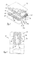
- the electrode arrangement 10 is a sandwich structure that comprises a generally planar sensing electrode 12, a shielding electrode 16 and an insulating layer 14 sandwiched by the sensing electrode 12 and the shielding electrode 16.
- the electrodes 12, 16 can be textile or film-based electrodes; the insulating layer 14 is preferably a textile, such as a knitted, woven or non-woven fabric. Preferably, the insulating layer 14 comprises a 3D spacer fabric.
- the electrodes 12, 16 are shown generally U-shaped. It should be noted, however, that other shapes are possible and, in some cases even desirable.
- the shape of the electrodes 12, 16 can be adjusted depending on the seat design, namely the geometry of seam lines 34 and crimp channels along which the seat cover is attached to the cushion. To further enhance the haptic properties of the electrode arrangement 10, it may be arranged in a felt pocket or, as shown, between two outer fabric layers 18, 20.
- the electrode arrangement 10 may further be protected by a moisture barrier layer. This may be arranged above the sensing electrode 12, e.g. above the fabric layer 20 or between the latter and the sensing electrode 12. Alternatively, the fabric layer 20 can comprise or be made of moisture resistant material and serve itself as a moisture barrier layer.
- the system executes a measurement routine, in which a control circuit (not shown), such as an application-specific integrated circuit (ASIC), applies a sinusoidal oscillating signal to the shielding electrode 16, while it keeps the sensing electrode 12 essentially at the same potential as the shielding electrode 16. lf the capacitance between the sensing electrode 12 and chassis ground changes, e.g. because of a passenger on the seat 32, the loading current drawn by the sensing electrode 12 changes.
- the control circuit measures the current drawn by the sensing electrode 12, which allows detecting and classifying an occupant on the seat 32.
- the shielding electrode 16 is driven with the same voltage as the sensing electrode 12, the sensing electrode 12 is only sensitive into the direction facing away from the shielding electrode 16, i.e. in direction of the upper surface of seat portion 30.
- the capacitive occupant classification system can determine if the seat 32 is vacant, equipped with a child seat or occupied by a passenger.
- the sensing electrode 12 and the shielding electrode 16 can be connected to the control circuit by electric lines 22, 24. Although these are represented in Fig. 1 as separate lines, it is preferable that they are both integrated in single coaxial cable.
- the electric line 24 corresponds to the core conductor of the coaxial cable while the electric line 22 corresponds to the conductive sheath of the coaxial cable. Terminals 22a and 24a of the electric lines 22, 24 are connected to the control circuit of capacitive occupancy classification system.
- a diode 26 and a capacitor 27 are arranged in parallel between the shielding electrode 16 and the sensing electrode 12.
- the forward direction of the diode 26 is from shielding electrode 16 to sensing electrode 12.
- the diode 26 is substantially passive, as the electrodes 12, 16 are driven with the same voltage.
- the capacitor 27 serves to reduce electromagnetic interference (EMI).
- the accuracy of the occupancy state determined in the measurement routine obviously depends on whether the system is operating properly.
- the system therefore should be able to determine failures, caused e.g. by an interrupted circuit, a short-circuit or seat wetness.
- a wet seat condition may affect occupant classification. Specifically, if the seat 32 is unoccupied but wet, the loading current drawn by the sensing electrode may be as large as if an adult were seated on the seat 32.
- a system check routine is therefore regularly run, which detects system failures.
- Figs. 3 and 4 illustrate a basic embodiment of a method or procedure 100 for operating an occupancy classification system.
- a DC voltage difference U 2 is applied between the terminals 22a and 24a of the electric lines 22, 24 in forward direction of the diode 26, i.e. the terminal 24a (and thus the shielding electrode 16) is brought to a higher electric potential than the terminal 22a (and thus the sensing electrode 12).
- the control circuit can determine, at 102, that a current flows between the terminals 22a and 24a.
- step 106 If, at decision step 104, despite of the voltage difference U 2 , no or too small a current flows between the terminals 22a, 24a, the system goes into a failure mode (step 106) in which all measurements are suspended.
- the driver may be informed of the failure by a warning signal, e.g. a warning light.
- step 108 another DC voltage difference U 1 is applied, at step 108, between the terminals 22a and 24a, this time in reverse direction of the diode 26, i.e. the terminal 22a (and thus the sensing electrode 12) is brought to a higher electric potential than the terminal 24a (and thus the shielding electrode 16).
- the current flowing between the sensing electrode 12 and the shielding electrode 16 is measured (step 110). Under ideal conditions, i.e. assuming an ideal diode 26 and otherwise perfect insulation between the sensing electrode 12 and the shielding electrode 16, no current would be measured.
- leakage current I L some current, so called leakage current I L , may flow in reverse direction through the diode and along current paths, due to imperfect insulation, between the sensing and shielding electrodes.
- the leakage current I L caused by the voltage difference U 1 is small, i.e. below a certain reference value. If, at decision step 112, it is determined that the leakage current I L exceeds the reference value I REF , the insulation between the sensing electrode 12 and the shielding electrode 16 is deemed deteriorated. This can be due to a failure of the insulation layer 14, e.g. as a consequence of stress, or to the seat 32 being moist. Naturally, if the insulation of the sensing electrode 12 is deteriorated, the capacitance measurement cannot be relied upon any more.
- step 118 if too high a leakage current I L is measured, it is best not to carry out the capacitance measurement of step 118. If the leakage current I L is below the reference value I REF , occupant detection is carried out as explained above by running the measurement routine 118. The procedure 100 is executed periodically, e.g. every 1 s (set in step 120) to detect possible changes of the occupancy etc.
- the leakage current I L between the sensing electrode 12 and the shielding electrode 16 is due to electrolytic conduction.
- the sensing electrode 12 acts as anode
- the shielding electrode 16 as cathode.
- a drawback of this testing method is that the anode gradually corrodes, which affects the lifetime of the entire system.
- applying the voltage difference U 1 in reverse direction of the diode 26 is therefore terminated (step 114) as soon as a leakage current I L exceeding the reference value I REF is determined, in order to minimise the effect of the electrolysis on the electrodes 12, 16.
- the system switches into failure mode (step 116), which is also indicated to the driver by a warning signal.
- the system then schedules (step 116) a new execution of the system check routine, where the waiting time between the last and the next execution of the system check routine is set to a much higher value than the duration of a cycle.
- the waiting time is set to at least 10 s. Waiting times in the range from 1 to 10 minutes are still more preferable, because drying of a vehicle seat 32 normally takes considerable time.
- Fig. 11 illustrates a variant of the procedure of Fig. 3, from which the variant differs in that the steps 101 and 102 have been replaced by steps 101 a and 102a.
- a current source is connected between the terminals 22a and 24a and feeds a predefined DC current through connection line 22, the shielding electrode 16, the diode 26, the sensing electrode 12 and the connection line 24, in forward direction of the diode.
- the current source behaves so as to apply a second voltage difference U 2 between the terminals 22a and 24a of the electric lines 22, 24, which can be measured.
- the voltage difference U 2 necessary for establishing the predefined current is high in comparison to the normal situation. This allows then to decide in step 104 whether the circuit is deemed interrupted or working properly.
- Fig. 4 shows the voltages on the electrodes 12, 16 during a complete cycle of the system operation procedure 100, during which no failure was detected.
- the dotted line 36 shows the voltage applied to the sensing electrode 12, the dashed line 38 the voltage applied to the shielding electrode 16 as a function of time t.
- Zero voltage corresponds to chassis ground. It has proven to be advantageous if the mean voltage difference over an entire cycle of the procedure 100 is zero. This translates graphically in that the areas under the dashed curve 38 and the dotted curve 36 are equal.
- U 2 is applied (or the corresponding current fed to the circuit), i.e. the shielding electrode 16 is set at a higher potential than the sensing electrode 12.
- a second time interval from t 2 to t 3 , U 1 is applied, i.e. the sensing electrode 12 is set at a higher potential than the shielding electrode 16.
- the voltage differences U 1 and U 2 are represented as being constant in Fig. 4, those skilled will note that these voltage differences may also be implemented variable in time.
- the second voltage difference U 2 is applied (or the corresponding current is fed to the circuit) for about 24 ms and the first voltage difference U 1 for about 20 ms (unless applying the first voltage difference is stopped in response to too high a leakage current I L ).
- the capacitance measurement is carried out. During the third time interval (typical duration: 50 ms), the voltage applied to sensing electrode 12 and shielding electrode 16 is the same in amplitude and phase.
- the voltage difference U 2 which is in forward direction of the diode 26, depends on the current-voltage characteristic of the diode 26. For instance, the voltage drop across a normal silicon diode conducting diode is approximately 0.6 to 0.7 V. The voltage drop may be different for other diode types.
- Fig. 5 shows a flow chart illustrating another embodiment of a procedure 100' for operating a capacitive occupant classification system.
- the occupant classification system first runs a system check routine to determine a potential failure of the system.
- a first voltage difference U 1 is applied (step 108') between the terminals 22a and 24a in reverse direction of the diode 26 by applying a higher potential to terminal 22a than to terminal 24a.
- the resulting leakage current I L is measured (step 110') and it is tested (step 112') whether it lies below or above the reference value I REF .
- the first voltage difference U 1 is gradually increased up to a preset maximum value (steps 113' and 115'), while the resulting leakage current is monitored (step 112'). It may be noted that the reference value I REF the leakage current is compared to can be depending on the currently applied first voltage difference U 1 .
- step 113' it is tested whether the preset maximum value U max of the first voltage difference U 1 has been reached. If this is the case and the leakage current I L has remained below the reference value I REF , a second voltage difference U 2 is applied between the sensing electrode 12 and the shielding electrode 16 to test for a possible interruption of the circuit (step 101'). The second voltage difference U 2 is applied in forward direction of the diode 26.
- step 102' The current that flows through the series circuit of the electric line 22, the shielding electrode 16, the diode 26, the sensing electrode 12 and the electric wire 24 is tested at step 102'. If no or only a small current flows through the circuit, it is concluded (at decision step 104') that the circuit is interrupted and the system switches into a failure mode (step 106'). A warning signal is issued that informs the driver that the occupant classification system is not operational and needs servicing. In the opposite case, the measurement routine is carried out (step 118') and the occupancy state of the vehicle seat is determined. A next execution of the procedure 100' is scheduled after a short waiting time (step 120').
- step 112' it has been found that the leakage current I L between the electrodes 12, 16 is too high, applying the first voltage difference is immediately stopped (step 114') and a next execution of the procedure 100' is scheduled (step 116') after a waiting time that is longer than the waiting time set in step 120'.
- the waiting time until the next execution of the procedure 100' may be computed as a function of the measured leakage current I L and the first voltage difference U 1 applied between the electrodes 12, 16. If, for example, a relatively high leakage current I L has been measured at a low applied voltage difference U 1 , this may indicate that the seat 32 is very wet. As a consequence, the waiting time could be increased to give the seat 32 more time to dry. If, on the contrary, the too high leakage current I L has only been measured at a higher applied voltage difference U 1 , this may indicate that the seat 32 is only slightly wet. In this case the waiting time may be set a lower value than in the first case.
- Fig. 6 shows a flow chart of yet another procedure 100" for operating the occupancy classification system.
- the main difference with respect to the previous embodiment is that testing for circuit interruption is performed before testing for leakage current. Only if the system passes the circuit interruption test, the leakage current I L is measured. More specifically, the second voltage difference U 2 (in forward direction of the diode 26) is applied in step 101". The current flowing in response to that is measured at 102". If the circuit is interrupted (decision step 104"), the system switches into failure mode (step 106") and indicates a failure to the driver. In the other case, a first voltage difference U 1 is applied (step 108") between the electrodes 12, 16 (in reverse direction of the diode 26).
- the resulting leakage current I L is measured (step 110") and compared to the reference value I REF .
- the first voltage difference U 1 is increased while the leakage current is monitored (steps 112", 113" and 115"). If the leakage current I L at some moment exceeds the reference value I REF , application of the voltage difference is immediately stopped (step 114") and the system switches to a failure mode (step 116"). This is indicated to the driver and a next execution of the system check routine is scheduled.
- the first voltage difference U 1 is only increased up to a predefined maximum value U max .
- step 118 the measurement routine is run (step 118"), wherein the occupancy state of the seat is determined.
- the waiting time scheduled in this case corresponds to the repetition rate under proper operating conditions.
- steps 101' and 102' respectively 101" and 102" can be replaced with steps 101 a and 102a as discussed above with reference to Fig. 11. Adapting the tests 104' and 104" accordingly is deemed within the reach of those skilled in the art.
- the electrode arrangement 10 is provided with a plurality of local test regions 28 in which electrolytic conduction between the sensing electrode 12 and the shielding electrode 16 is enhanced with respect to outside the test regions 28 if the seat is wet. In absence of such test regions 28, electrolysis would occur in random locations of the electrode arrangement 10 during the measurement of the leakage current I L . If however, as in the present electrode arrangement 10, one provides for conditions favourable to electrolytic conduction in certain local regions 28 (as opposed to the electrode arrangement 10 as a whole), the leakage current between the electrodes 12, 16 will pass in these regions 28. The anode may still corrode, but instead of this happening at random spots, this now happens at defined locations.
- the local test regions 28 are distributed over the electrode arrangement 10 so as to be associated with different portions of the seating portion 30 when the electrode arrangement 10 is integrated therein.
- An arrangement with a plurality of test regions 28 is preferred over one with only one local test region 28, as wetness does not always occur homogeneously over the entire seating portion 32.
- the local test regions may be formed as lobes or appendices projecting laterally, i.e. in the plane of the electrode arrangement, from the body portion of the electrode arrangement 10.
- Figs. 7 to 10 show different configurations of local test regions 28 in which electrolytic conduction between the sensing electrode 12 and the shielding electrode 16 is enhanced.
- a local test region 28 may be a region of the electrode arrangement 10, where the distance between the sensing electrode 12 and the shielding electrode 16 is reduced with respect to outside the test region 28.
- E 1 U/d 1
- E 2 U/d 2
- I EL the electric current due to the ions travelling between the electrodes 12, 16. This shows that the electric current density between the electrodes 12, 16 inside the local test regions 28 is increased with respect to outside these regions.
- the thickness of the electrodes 12, 16 may be larger in the test regions 28 than outside the test regions. As corrosion occurs mostly in the test regions, providing the electrodes 12, 16 with more material in these regions increases the lifetime of the system.
- Fig. 7 only the sensing electrode 12 is shown having an increased material thickness. Such a configuration would be suitable if during measurement of the leakage current I L , the sensing electrode 12 is the anode, which corrodes. It should be noted that a configuration wherein only the shielding electrode 16 has an increased thickness would also be possible. In this case, the latter should be used as the anode during the measurement of the leakage current. In the embodiment of Fig. 8, both the sensing electrode 12 and the shielding electrode 16 have the extra thickness in the test region 28.
- Figs. 9 and 10 show another configuration of a local test region 28. Only in these local test regions 28, a hydrophilic thread 40 extends between the sensing electrode 12 and the shielding electrode 16. Outside the local test region 28, the hydrophilic thread 40 is absent. If the seat 32 is humid or wet, the hydrophilic thread 40 will draw water and thereby in favour the formation of a continuous water column between the electrodes 12, 16. As a result, electrolytic conduction in the test region 28 is enhanced with respect to outside the test region. It should be noted that a hydrophilic thread 40 can be used as an alternative or in addition to reduced distance between the electrodes 12, 16. As in the previous configurations, additional material thickness of the electrodes (or one of the electrodes) inside the local test region 28 is advantageous for increasing the system lifetime.
- Fig. 10 shows an embodiment of a local test region in which both reduced distance between the electrodes 12, 16 and a hydrophilic thread 40 are used for enhancing electrolytic conduction. Outside the local test region, hydrophobic thread 42 is used to sew together the electrode assembly 10.
Landscapes
- Engineering & Computer Science (AREA)
- Mechanical Engineering (AREA)
- Seats For Vehicles (AREA)
- Testing Of Short-Circuits, Discontinuities, Leakage, Or Incorrect Line Connections (AREA)
Abstract
The method concerns operating a capacitive occupant classification system that comprises a sensing electrode and a shielding electrode arranged in a vehicle seat. The method comprises a measurement routine for classifying an occupancy state of the vehicle seat and a system check routine. In particular, the system check routine includes applying a first DC voltage difference between the sensing electrode and the shielding electrode and determining a leakage current caused by this first voltage difference between the sensing and shielding electrodes. Applying of the first voltage difference is terminated as soon as the testing indicates that the determined leakage current is not comprised in the predefined range of acceptable values, e.g. if the leakage current exceeds a certain reference value that indicates the highest tolerable leakage current.
Description
- The present invention generally relates to a method for operating a capacitive occupant classification system, more specifically to such a method including a system check routine.
- A capacitive seat occupancy classification system and method are proposed in
EP 1 457 391 A1 . The system comprises first and second capacitive electrode arrangements in a vehicle compartment. The first capacitive electrode arrangement is located in a seat of the vehicle and includes a sensing electrode and a shielding electrode. The sensing electrode is directed towards the occupant of the seat, whereas the shielding electrode is directed towards the seat frame. An insulating layer separates the sensing from the shielding electrode. The system can operate in a so-called loading mode, in which the sensing electrode and the shielding electrode are driven by the same AC voltage, so that the shielding electrode prevents the electric field of the sensing electrode from coupling with the seat frame. This dramatically increases the sensitivity of the sensing electrode in direction of the occupant. Such an electrode configuration is also known fromUS 5,166,679 . - For safety-critical applications such as occupant classification, efforts are always made in order to make the system as reliable as possible. Methods for operating such systems therefore include regularly checking different system parameters in order to detection potential failures. For instance, it is known that a wet seat may affect the measurements of capacitive sensing systems.
EP 1 457 391 A1 therefore suggested measuring the electrical resistance between the sensing electrode and the shielding electrode to test whether the insulation layer between the electrodes is dry. - If the seat is wet, applying a DC voltage difference between two conductors such as the electrodes of the electrode arrangement may cause corrosion of the anode due to oxidation, which would affect the lifetime of the entire system.
- It is an object of the present invention to provide an improved method for operating a capacitive occupant classification system. This object is achieved by a method as claimed in claim 1.
- The method concerns operating a capacitive occupant classification system that comprises a sensing electrode and a shielding electrode arranged in a vehicle seat. The method comprises a measurement routine for classifying an occupancy state of the vehicle seat and a system check routine. In particular, the system check routine includes applying a first DC voltage difference between the sensing electrode and the shielding electrode and determining a leakage current caused by this first voltage difference between the sensing and shielding electrodes. According to an important aspect of the invention, applying of the first voltage difference is terminated as soon as the testing indicates that the determined leakage current is not comprised in the predefined range of acceptable values, e.g. if the determined leakage current exceeds a certain reference value that corresponds to the highest tolerable leakage current. As will be appreciated, the time during which electrolytic conduction occurs between the two electrodes is thus reduced to a minimum.
- According to a preferred embodiment of the method, the first voltage difference is gradually increased. Of course, while the first voltage difference is increased, the leakage current is determined in order to stop applying the voltage difference as soon as the determined leakage current is not comprised any more in the predefined range of acceptable values. This helps to further reduce corrosion of the electrodes.
- According to yet another preferred embodiment of the method, the system check routine includes scheduling a next execution of the system check routine after a certain waiting time, the waiting time being determined depending on whether the determined leakage current is comprised in the predefined range of acceptable values or not. The method for operating a capacitive occupant classification system is normally executed repeatedly to make sure that a possible change of the occupation state of the seat is detected. As long as no failure is detected, the method is repeated e.g. every second. If however it is determined that there is a failure, namely an unacceptably high leakage current, the method is repeated less often. As one of the reasons for high leakage current is the seat being wet, reducing the repetition rate of the system check routine and thus of the applying of a DC voltage difference, results in less corrosion. In a preferred variant of the method, the waiting time is determined based on both the determined leakage current and the first voltage difference. For instance, a high leakage current at a low first voltage difference may be due to the seat being very wet. In this case, it is preferable to wait a longer time, e.g. from a few tens of minutes to hours, because drying of the seat is not a matter of seconds but rather of minutes or even hours. Preferably, the waiting time is comprised in a range from 0.1 s to 2 s if the determined leakage current is comprised in the predefined range of acceptable values and in a range from 5 s to 60 minutes, more preferably between 10 s and 20 minutes, if the determined leakage current is not comprised in the predefined range of acceptable values.
- If the sensing electrode and the shielding electrode are electrically connected through a diode to form a series circuit, the first voltage difference is applied in reverse direction of the diode, i.e. so that the diode essentially blocks the current that would result from the voltage difference. If the shielding electrode and the sensing electrode are connected this way, the system check routine may include applying a second DC voltage difference in forward direction of the diode, i.e. so that the current is not blocked, and determining a current flowing through the series circuit in response to the second voltage difference for determining whether the series circuit is interrupted. If no or only little current flows in response to the applying of the second voltage difference, it can be concluded that the said series circuit is interrupted somewhere. In this case, the system may switch into a failure mode and signalise the failure to the driver. Any capacitance measurement made in this case cannot be relied upon, so that such a measurement is preferably omitted in case of circuit interruption. The first voltage difference may be applied during at least one first time interval, wherein the second voltage difference may be applied during at least one second time interval. Tests have shown that it is advantageous to adjust the first and second voltage differences, as well as the time interval durations in such a way that an integral of the first voltage difference over the at least one first time interval is substantially additively inverse to an integral of the second voltage difference over the at least one second time interval. It should be noted that the time intervals can be generalised time intervals, i.e. time intervals comprising more than one continuous portion. In this case, the first and second time intervals may be interlaced.
- Alternatively to applying a second voltage difference and measuring the resulting current, one may feed, by means of a current source, a predefined current through the series circuit in forward direction of the diode and determine the corresponding second voltage difference between the sensing electrode and the shielding electrode, i.e. the voltage difference that the current source has to build up to cause the flow of the predefined current, for deciding whether the series circuit is interrupted. In this case, the first voltage difference is applied during at least one first time interval and the current is fed through the series circuit in forward direction of the diode during at least one second time interval in such a way that the integral of the first voltage difference over the at least one first time interval is substantially additively inverse to the integral of the second voltage difference over the at least one second time interval.
- For sake of completeness, it should be mentioned that the measurement routine preferably includes driving the sensing electrode and the shielding electrode with an oscillating voltage, i.e. applying to both electrodes the same oscillating voltage, and determining capacitive coupling between the sensing electrode and an object or occupant placed on the vehicle seat, e.g. by measuring a loading current drawn by said sensing electrode. Most preferably, the measurement routine is executed only if the determined leakage current is comprised in the range of acceptable values.
- Further details and advantages of the present invention will be apparent from the following detailed description of not limiting embodiments with reference to the attached drawings, wherein:
- Fig. 1 is an exploded perspective view of an electrode arrangement of a capacitive occupancy classification system;
- Fig. 2 is a schematic top view of a vehicle seat equipped with the electrode arrangement of Fig. 1;
- Fig. 3 is a flow chart of a first procedure for operating a capacitive occupancy classification system;
- Fig. 4 is a schematic representation of the voltages applied during the procedure illustrated in Fig. 3;
- Fig. 5 is a flow chart of a second procedure for operating a capacitive occupancy classification system;
- Fig. 6 is a flow chart of a third procedure for operating a capacitive occupancy classification system;
- Fig. 7 is a vertical cross sectional view of an electrode arrangement provided with local test regions of a first configuration;
- Fig. 8 is a vertical cross sectional view of an electrode arrangement provided with local test regions of a second configuration;
- Fig. 9 is a vertical cross sectional view of an electrode arrangement provided with local test regions of a third configuration;
- Fig. 10 is a vertical cross sectional view of an electrode arrangement provided with local test regions of a fourth configuration;
- Fig. 11 is a flow chart of a variant of the procedure of Fig. 3.
- An
electrode arrangement 10 of a capacitive occupant classification system is shown in Figs. 1 and 2. Theelectrode arrangement 10 is a sandwich structure that comprises a generallyplanar sensing electrode 12, a shieldingelectrode 16 and an insulatinglayer 14 sandwiched by thesensing electrode 12 and the shieldingelectrode 16. Theelectrodes layer 14 is preferably a textile, such as a knitted, woven or non-woven fabric. Preferably, the insulatinglayer 14 comprises a 3D spacer fabric. When theelectrode arrangement 10 is operationally integrated into theseating portion 30 of avehicle seat 32, theelectrodes seating portion 30, with the sensing electrode being closer to that upper surface than the shieldingelectrode 16. Theelectrodes electrodes seam lines 34 and crimp channels along which the seat cover is attached to the cushion. To further enhance the haptic properties of theelectrode arrangement 10, it may be arranged in a felt pocket or, as shown, between two outer fabric layers 18, 20. Theelectrode arrangement 10 may further be protected by a moisture barrier layer. This may be arranged above thesensing electrode 12, e.g. above thefabric layer 20 or between the latter and thesensing electrode 12. Alternatively, thefabric layer 20 can comprise or be made of moisture resistant material and serve itself as a moisture barrier layer. - For occupancy detection the system executes a measurement routine, in which a control circuit (not shown), such as an application-specific integrated circuit (ASIC), applies a sinusoidal oscillating signal to the shielding
electrode 16, while it keeps thesensing electrode 12 essentially at the same potential as the shieldingelectrode 16. lf the capacitance between the sensingelectrode 12 and chassis ground changes, e.g. because of a passenger on theseat 32, the loading current drawn by thesensing electrode 12 changes. The control circuit measures the current drawn by thesensing electrode 12, which allows detecting and classifying an occupant on theseat 32. As the shieldingelectrode 16 is driven with the same voltage as thesensing electrode 12, thesensing electrode 12 is only sensitive into the direction facing away from the shieldingelectrode 16, i.e. in direction of the upper surface ofseat portion 30. Thus, the capacitive occupant classification system can determine if theseat 32 is vacant, equipped with a child seat or occupied by a passenger. - The
sensing electrode 12 and the shieldingelectrode 16 can be connected to the control circuit byelectric lines electric line 24 corresponds to the core conductor of the coaxial cable while theelectric line 22 corresponds to the conductive sheath of the coaxial cable.Terminals 22a and 24a of theelectric lines - It is also shown in Fig. 1 that a
diode 26 and acapacitor 27 are arranged in parallel between the shieldingelectrode 16 and thesensing electrode 12. The forward direction of thediode 26 is from shieldingelectrode 16 to sensingelectrode 12. During the measurement routine, thediode 26 is substantially passive, as theelectrodes capacitor 27 serves to reduce electromagnetic interference (EMI). - The accuracy of the occupancy state determined in the measurement routine obviously depends on whether the system is operating properly. The system therefore should be able to determine failures, caused e.g. by an interrupted circuit, a short-circuit or seat wetness. As it has been said before, a wet seat condition may affect occupant classification. Specifically, if the
seat 32 is unoccupied but wet, the loading current drawn by the sensing electrode may be as large as if an adult were seated on theseat 32. A system check routine is therefore regularly run, which detects system failures. - Figs. 3 and 4 illustrate a basic embodiment of a method or
procedure 100 for operating an occupancy classification system. In a first time (Step 101 in Fig. 3), e.g. after the driver has turned the ignition key, a DC voltage difference U2 is applied between theterminals 22a and 24a of theelectric lines diode 26, i.e. theterminal 24a (and thus the shielding electrode 16) is brought to a higher electric potential than the terminal 22a (and thus the sensing electrode 12). If the electric circuit of theelectric line 22, the shieldingelectrode 16, thediode 26, thesensing electrode 12 and theelectric line 24 is not interrupted in some place, the control circuit can determine, at 102, that a current flows between theterminals 22a and 24a. If, atdecision step 104, despite of the voltage difference U2, no or too small a current flows between theterminals 22a, 24a, the system goes into a failure mode (step 106) in which all measurements are suspended. The driver may be informed of the failure by a warning signal, e.g. a warning light. - If, however, the system has passed the
first test 104, another DC voltage difference U1 is applied, atstep 108, between theterminals 22a and 24a, this time in reverse direction of thediode 26, i.e. the terminal 22a (and thus the sensing electrode 12) is brought to a higher electric potential than the terminal 24a (and thus the shielding electrode 16). Again, the current flowing between the sensingelectrode 12 and the shieldingelectrode 16 is measured (step 110). Under ideal conditions, i.e. assuming anideal diode 26 and otherwise perfect insulation between the sensingelectrode 12 and the shieldingelectrode 16, no current would be measured. Under real conditions, some current, so called leakage current IL, may flow in reverse direction through the diode and along current paths, due to imperfect insulation, between the sensing and shielding electrodes. Normally, the leakage current IL caused by the voltage difference U1 is small, i.e. below a certain reference value. If, atdecision step 112, it is determined that the leakage current IL exceeds the reference value IREF, the insulation between the sensingelectrode 12 and the shieldingelectrode 16 is deemed deteriorated. This can be due to a failure of theinsulation layer 14, e.g. as a consequence of stress, or to theseat 32 being moist. Naturally, if the insulation of thesensing electrode 12 is deteriorated, the capacitance measurement cannot be relied upon any more. Thus if too high a leakage current IL is measured, it is best not to carry out the capacitance measurement ofstep 118. If the leakage current IL is below the reference value IREF, occupant detection is carried out as explained above by running themeasurement routine 118. Theprocedure 100 is executed periodically, e.g. every 1 s (set in step 120) to detect possible changes of the occupancy etc. - If, for one reason or another, the
seat 32 is wet, the leakage current IL between the sensingelectrode 12 and the shieldingelectrode 16 is due to electrolytic conduction. As long as the voltage difference U1 is applied, thesensing electrode 12 acts as anode, the shieldingelectrode 16 as cathode. A drawback of this testing method is that the anode gradually corrodes, which affects the lifetime of the entire system. In the proposed method, applying the voltage difference U1 in reverse direction of thediode 26 is therefore terminated (step 114) as soon as a leakage current IL exceeding the reference value IREF is determined, in order to minimise the effect of the electrolysis on theelectrodes vehicle seat 32 normally takes considerable time. - Fig. 11 illustrates a variant of the procedure of Fig. 3, from which the variant differs in that the
steps steps 101 a and 102a. In step 101 a, a current source is connected between theterminals 22a and 24a and feeds a predefined DC current throughconnection line 22, the shieldingelectrode 16, thediode 26, thesensing electrode 12 and theconnection line 24, in forward direction of the diode. To establish this current, the current source behaves so as to apply a second voltage difference U2 between theterminals 22a and 24a of theelectric lines step 104 whether the circuit is deemed interrupted or working properly. - Fig. 4 shows the voltages on the
electrodes system operation procedure 100, during which no failure was detected. The dottedline 36 shows the voltage applied to thesensing electrode 12, the dashedline 38 the voltage applied to the shieldingelectrode 16 as a function of time t. Zero voltage corresponds to chassis ground. It has proven to be advantageous if the mean voltage difference over an entire cycle of theprocedure 100 is zero. This translates graphically in that the areas under the dashedcurve 38 and the dottedcurve 36 are equal. In a first time interval from time t1 to time t2, U2 is applied (or the corresponding current fed to the circuit), i.e. the shieldingelectrode 16 is set at a higher potential than thesensing electrode 12. In a second time interval, from t2 to t3, U1 is applied, i.e. thesensing electrode 12 is set at a higher potential than the shieldingelectrode 16. Although the voltage differences U1 and U2 are represented as being constant in Fig. 4, those skilled will note that these voltage differences may also be implemented variable in time. According to a preferred embodiment, the second voltage difference U2 is applied (or the corresponding current is fed to the circuit) for about 24 ms and the first voltage difference U1 for about 20 ms (unless applying the first voltage difference is stopped in response to too high a leakage current IL). In a third time interval, from t3 to t4, the capacitance measurement is carried out. During the third time interval (typical duration: 50 ms), the voltage applied to sensingelectrode 12 and shieldingelectrode 16 is the same in amplitude and phase. - Those skilled will note that the voltage difference U2, which is in forward direction of the
diode 26, depends on the current-voltage characteristic of thediode 26. For instance, the voltage drop across a normal silicon diode conducting diode is approximately 0.6 to 0.7 V. The voltage drop may be different for other diode types. - Fig. 5 shows a flow chart illustrating another embodiment of a procedure 100' for operating a capacitive occupant classification system. The occupant classification system first runs a system check routine to determine a potential failure of the system. To determine the leakage current IL, a first voltage difference U1 is applied (step 108') between the
terminals 22a and 24a in reverse direction of thediode 26 by applying a higher potential to terminal 22a than to terminal 24a. The resulting leakage current IL is measured (step 110') and it is tested (step 112') whether it lies below or above the reference value IREF. - If this is the case, the first voltage difference U1 is gradually increased up to a preset maximum value (steps 113' and 115'), while the resulting leakage current is monitored (step 112'). It may be noted that the reference value IREF the leakage current is compared to can be depending on the currently applied first voltage difference U1. In step 113', it is tested whether the preset maximum value Umax of the first voltage difference U1 has been reached. If this is the case and the leakage current IL has remained below the reference value IREF, a second voltage difference U2 is applied between the sensing
electrode 12 and the shieldingelectrode 16 to test for a possible interruption of the circuit (step 101'). The second voltage difference U2 is applied in forward direction of thediode 26. The current that flows through the series circuit of theelectric line 22, the shieldingelectrode 16, thediode 26, thesensing electrode 12 and theelectric wire 24 is tested at step 102'. If no or only a small current flows through the circuit, it is concluded (at decision step 104') that the circuit is interrupted and the system switches into a failure mode (step 106'). A warning signal is issued that informs the driver that the occupant classification system is not operational and needs servicing. In the opposite case, the measurement routine is carried out (step 118') and the occupancy state of the vehicle seat is determined. A next execution of the procedure 100' is scheduled after a short waiting time (step 120'). - If at decision step 112', it has been found that the leakage current IL between the
electrodes electrodes seat 32 is very wet. As a consequence, the waiting time could be increased to give theseat 32 more time to dry. If, on the contrary, the too high leakage current IL has only been measured at a higher applied voltage difference U1, this may indicate that theseat 32 is only slightly wet. In this case the waiting time may be set a lower value than in the first case. - Fig. 6 shows a flow chart of yet another
procedure 100" for operating the occupancy classification system. The main difference with respect to the previous embodiment is that testing for circuit interruption is performed before testing for leakage current. Only if the system passes the circuit interruption test, the leakage current IL is measured. More specifically, the second voltage difference U2 (in forward direction of the diode 26) is applied instep 101". The current flowing in response to that is measured at 102". If the circuit is interrupted (decision step 104"), the system switches into failure mode (step 106") and indicates a failure to the driver. In the other case, a first voltage difference U1 is applied (step 108") between theelectrodes 12, 16 (in reverse direction of the diode 26). The resulting leakage current IL is measured (step 110") and compared to the reference value IREF. The first voltage difference U1 is increased while the leakage current is monitored (steps 112", 113" and 115"). If the leakage current IL at some moment exceeds the reference value IREF, application of the voltage difference is immediately stopped (step 114") and the system switches to a failure mode (step 116"). This is indicated to the driver and a next execution of the system check routine is scheduled. The first voltage difference U1 is only increased up to a predefined maximum value Umax. If the leakage current IL remains below the reference value IREF even with the first voltage difference U1 at maximum ( U1≥ Umax), the measurement routine is run (step 118"), wherein the occupancy state of the seat is determined. The waiting time scheduled in this case (instep 120") corresponds to the repetition rate under proper operating conditions. - With regard to the procedures illustrated in Figs. 5 and 6, it should be mentioned that steps 101' and 102' respectively 101" and 102" can be replaced with
steps 101 a and 102a as discussed above with reference to Fig. 11. Adapting thetests 104' and 104" accordingly is deemed within the reach of those skilled in the art. - As can be seen in Figs. 1 and 2, the
electrode arrangement 10 is provided with a plurality oflocal test regions 28 in which electrolytic conduction between the sensingelectrode 12 and the shieldingelectrode 16 is enhanced with respect to outside thetest regions 28 if the seat is wet. In absence ofsuch test regions 28, electrolysis would occur in random locations of theelectrode arrangement 10 during the measurement of the leakage current IL. If however, as in thepresent electrode arrangement 10, one provides for conditions favourable to electrolytic conduction in certain local regions 28 (as opposed to theelectrode arrangement 10 as a whole), the leakage current between theelectrodes regions 28. The anode may still corrode, but instead of this happening at random spots, this now happens at defined locations. Thelocal test regions 28 are distributed over theelectrode arrangement 10 so as to be associated with different portions of theseating portion 30 when theelectrode arrangement 10 is integrated therein. An arrangement with a plurality oftest regions 28 is preferred over one with only onelocal test region 28, as wetness does not always occur homogeneously over theentire seating portion 32. In Fig. 2, it is also shown that the local test regions may be formed as lobes or appendices projecting laterally, i.e. in the plane of the electrode arrangement, from the body portion of theelectrode arrangement 10. - Figs. 7 to 10 show different configurations of
local test regions 28 in which electrolytic conduction between the sensingelectrode 12 and the shieldingelectrode 16 is enhanced. As shown in Figs. 7 and 8, alocal test region 28 may be a region of theelectrode arrangement 10, where the distance between the sensingelectrode 12 and the shieldingelectrode 16 is reduced with respect to outside thetest region 28. When there is a voltage difference between the sensingelectrode 12 and the shieldingelectrode 16, the resulting electric field will have higher field strength inside thelocal test region 28 than outside thelocal test region 28. This can easily be deduced from the relation E= U/d, where E is the electric field strength, U is the potential difference between theelectrodes electrodes test region 28, E2 the electric field strength outside thetest region 28, one obtains E1= U/d1 >> E2= U/d2, if d1<<d2, where d1 is the distance between theelectrodes test region 28, d2 the distance between theelectrodes test region 28. At least at the beginning of an electrolysis, electrolytic conduction in thetest region 28 can be expressed as IEL= . U/d1, where is a proportionality constant depending on the solved ions and the area of thetest region 28 and IEL is the electric current due to the ions travelling between theelectrodes electrodes local test regions 28 is increased with respect to outside these regions. - The figures show that the thickness of the
electrodes test regions 28 than outside the test regions. As corrosion occurs mostly in the test regions, providing theelectrodes sensing electrode 12 is shown having an increased material thickness. Such a configuration would be suitable if during measurement of the leakage current IL, thesensing electrode 12 is the anode, which corrodes. It should be noted that a configuration wherein only the shieldingelectrode 16 has an increased thickness would also be possible. In this case, the latter should be used as the anode during the measurement of the leakage current. In the embodiment of Fig. 8, both thesensing electrode 12 and the shieldingelectrode 16 have the extra thickness in thetest region 28. - Figs. 9 and 10 show another configuration of a
local test region 28. Only in theselocal test regions 28, ahydrophilic thread 40 extends between the sensingelectrode 12 and the shieldingelectrode 16. Outside thelocal test region 28, thehydrophilic thread 40 is absent. If theseat 32 is humid or wet, thehydrophilic thread 40 will draw water and thereby in favour the formation of a continuous water column between theelectrodes test region 28 is enhanced with respect to outside the test region. It should be noted that ahydrophilic thread 40 can be used as an alternative or in addition to reduced distance between theelectrodes local test region 28 is advantageous for increasing the system lifetime. Fig. 10 shows an embodiment of a local test region in which both reduced distance between theelectrodes hydrophilic thread 40 are used for enhancing electrolytic conduction. Outside the local test region,hydrophobic thread 42 is used to sew together theelectrode assembly 10. - One should remember that once a significant leakage current IL has been detected, applying the voltage difference U1 in reverse direction of the
diode 26 is stopped. In the present electrode arrangement the predominant part of the current due to electrolytic conduction is concentrated in thelocal test regions 28. Damage caused by the electrolysis to the electrodes therefore occurs mainly in the test regions and, if at all, to a much smaller extent outside the test regions. Furthermore, as electrolytic conduction is enhanced, a leakage current may be detected earlier (i.e. at a lower voltage difference U1) than in a conventional electrode arrangement for a capacitive occupancy detection system. - Those skilled will appreciate that the method for operating the capacitive sensing system disclosed herein can be used for a conventional system, i.e. one without local test regions. For the reasons discussed above, a capacitive sensing system, wherein the electrode arrangement is provided with local test regions is, however, preferred.
Claims (12)
- A method for operating a capacitive occupant classification system, said occupant classification system comprising a sensing electrode and a shielding electrode arranged in a vehicle seat, said method comprising a measurement routine for classifying an occupancy state of said vehicle seat and a system check routine, wherein said system check routine includes:applying a first voltage difference between said sensing electrode andsaid shielding electrode, anddetermining a leakage current caused by said first voltage difference between said sensing electrode and said shielding electrode,testing whether said determined leakage current is comprised in apredefined range of acceptable values,said method being characterized in that
said applying of said first voltage difference is terminated as soon as said testing indicates that said determined leakage current is not comprised in said predefined range of acceptable values. - The method according to claim 1, wherein said applying of said first voltage difference includes gradually increasing said first voltage difference.
- The method according to claim 1 or 2, wherein said system check routine includes scheduling a next execution of the system check routine after a certain waiting time and wherein said waiting time is determined depending on whether said determined leakage current is comprised in said predefined range of acceptable values.
- The method according to claim 3, wherein said waiting time is determined depending on said determined leakage current and said first voltage difference.
- The method according to claim 3 or 4, wherein said waiting time is comprised in a range from 0.1 s to 2 s if said determined leakage current is comprised in said predefined range of acceptable values and in a range from 5 s to 10 minutes if said determined leakage current is not comprised in said predefined range of acceptable values.
- The method according to any one of claims 1 to 5, wherein said sensing electrode and said shielding electrode are electrically connected through a diode to form a series circuit, and wherein said first voltage difference is applied in reverse direction of said diode.
- The method according to claim 6, wherein said system check routine comprises applying a second voltage difference in forward direction of said diode and determining a current flowing through said series circuit in response to said second voltage difference for determining whether said series circuit is interrupted.
- The method according to claim 7, wherein said first voltage difference is applied during at least one first time interval, wherein said second voltage difference is applied during at least one second time interval and wherein an integral of said first voltage difference over said at least one first time interval is substantially additively inverse to an integral of said second voltage difference over said at least one second time interval.
- The method according to claim 6, wherein said system check routine comprises feeding a current through said series circuit in forward direction of said diode and determining a second voltage difference between said sensing electrode and said shielding electrode for deciding whether said series circuit is interrupted.
- The method according to claim 9, wherein said first voltage difference is applied during at least one first time interval, wherein said current is fed through said series circuit in forward direction of said diode during at least one second time interval and wherein an integral of said first voltage difference over said at least one first time interval is substantially additively inverse to an integral of said second voltage difference over said at least one second time interval.
- The method according to any one of claims 1 to 10, wherein said measurement routine includes:driving said sensing electrode and said shielding electrode with an oscillating voltage,determining capacitive coupling between said sensing electrode andan object or occupant placed on said vehicle seat.
- The method according to any one of claims 1 to 11 wherein said measurement routine is executed only if said determined leakage current is comprised in said range of acceptable values.
Priority Applications (5)
| Application Number | Priority Date | Filing Date | Title |
|---|---|---|---|
| EP06115667A EP1870293A1 (en) | 2006-06-19 | 2006-06-19 | Capacitive occupant classification system operating method |
| JP2009515818A JP2009541723A (en) | 2006-06-19 | 2007-06-06 | Operation method of capacity type occupational grading system |
| EP07729965A EP2029398A1 (en) | 2006-06-19 | 2007-06-06 | Capacitive occupant classification system operating method |
| CNA2007800228887A CN101472769A (en) | 2006-06-19 | 2007-06-06 | Capacitive occupant classification system operating method |
| PCT/EP2007/055592 WO2007147735A1 (en) | 2006-06-19 | 2007-06-06 | Capacitive occupant classification system operating method |
Applications Claiming Priority (1)
| Application Number | Priority Date | Filing Date | Title |
|---|---|---|---|
| EP06115667A EP1870293A1 (en) | 2006-06-19 | 2006-06-19 | Capacitive occupant classification system operating method |
Publications (1)
| Publication Number | Publication Date |
|---|---|
| EP1870293A1 true EP1870293A1 (en) | 2007-12-26 |
Family
ID=37057265
Family Applications (2)
| Application Number | Title | Priority Date | Filing Date |
|---|---|---|---|
| EP06115667A Withdrawn EP1870293A1 (en) | 2006-06-19 | 2006-06-19 | Capacitive occupant classification system operating method |
| EP07729965A Withdrawn EP2029398A1 (en) | 2006-06-19 | 2007-06-06 | Capacitive occupant classification system operating method |
Family Applications After (1)
| Application Number | Title | Priority Date | Filing Date |
|---|---|---|---|
| EP07729965A Withdrawn EP2029398A1 (en) | 2006-06-19 | 2007-06-06 | Capacitive occupant classification system operating method |
Country Status (4)
| Country | Link |
|---|---|
| EP (2) | EP1870293A1 (en) |
| JP (1) | JP2009541723A (en) |
| CN (1) | CN101472769A (en) |
| WO (1) | WO2007147735A1 (en) |
Families Citing this family (7)
| Publication number | Priority date | Publication date | Assignee | Title |
|---|---|---|---|---|
| JP4702471B2 (en) | 2008-09-19 | 2011-06-15 | 株式会社デンソー | Method for adjusting electrostatic occupant detection device and electrostatic occupant detection device |
| JP4752956B2 (en) | 2009-06-16 | 2011-08-17 | 株式会社デンソー | Electrostatic occupant detection device |
| DE102009055121A1 (en) | 2009-12-22 | 2011-06-30 | Robert Bosch GmbH, 70469 | Sensing surface element e.g. plaster in medical area, has two capacitive sensors comprising two capacitor surfaces formed as partial regions of conductive layers and completely formed by non-conductive layer and conductive layers |
| DE102009055124A1 (en) | 2009-12-22 | 2011-06-30 | Robert Bosch GmbH, 70469 | Sensing surface element e.g. plaster in medical area, has transceivers receiving radio waves-request signal, outputting radio waves-response signal and completely formed by electrically non-conductive layer and two conductive layers |
| JP5639655B2 (en) * | 2010-09-28 | 2014-12-10 | 株式会社フジクラ | Capacitance sensor |
| CN102426859B (en) * | 2011-11-30 | 2015-03-04 | 中国科学院微电子研究所 | Method of detecting read speed disturbance and method of detecting program disturbance |
| US20230346608A1 (en) * | 2020-06-30 | 2023-11-02 | Essity Hygiene And Health Aktiebolag | Strip element for an absorbent hygiene article |
Citations (3)
| Publication number | Priority date | Publication date | Assignee | Title |
|---|---|---|---|---|
| US5166679A (en) | 1991-06-06 | 1992-11-24 | The United States Of America As Represented By The Administrator Of The National Aeronautics & Space Administration | Driven shielding capacitive proximity sensor |
| US6335684B1 (en) * | 1998-03-23 | 2002-01-01 | Bayerische Motoren Werke Aktiengesellschaft | Method for capacitative object recognition in motor vehicles |
| EP1457391A1 (en) | 2003-03-10 | 2004-09-15 | IEE INTERNATIONAL ELECTRONICS & ENGINEERING S.A. | System for detecting seat occupancy |
-
2006
- 2006-06-19 EP EP06115667A patent/EP1870293A1/en not_active Withdrawn
-
2007
- 2007-06-06 WO PCT/EP2007/055592 patent/WO2007147735A1/en not_active Ceased
- 2007-06-06 CN CNA2007800228887A patent/CN101472769A/en active Pending
- 2007-06-06 JP JP2009515818A patent/JP2009541723A/en not_active Withdrawn
- 2007-06-06 EP EP07729965A patent/EP2029398A1/en not_active Withdrawn
Patent Citations (3)
| Publication number | Priority date | Publication date | Assignee | Title |
|---|---|---|---|---|
| US5166679A (en) | 1991-06-06 | 1992-11-24 | The United States Of America As Represented By The Administrator Of The National Aeronautics & Space Administration | Driven shielding capacitive proximity sensor |
| US6335684B1 (en) * | 1998-03-23 | 2002-01-01 | Bayerische Motoren Werke Aktiengesellschaft | Method for capacitative object recognition in motor vehicles |
| EP1457391A1 (en) | 2003-03-10 | 2004-09-15 | IEE INTERNATIONAL ELECTRONICS & ENGINEERING S.A. | System for detecting seat occupancy |
Also Published As
| Publication number | Publication date |
|---|---|
| EP2029398A1 (en) | 2009-03-04 |
| JP2009541723A (en) | 2009-11-26 |
| WO2007147735A1 (en) | 2007-12-27 |
| CN101472769A (en) | 2009-07-01 |
Similar Documents
| Publication | Publication Date | Title |
|---|---|---|
| EP2029398A1 (en) | Capacitive occupant classification system operating method | |
| JP4229071B2 (en) | Capacitive sensor and occupant detection system | |
| US7436315B2 (en) | Passenger detection system | |
| US8078362B2 (en) | Electrostatic seat occupant detection system | |
| US20100102833A1 (en) | Sitting detection system | |
| US7497465B2 (en) | Capacitance type sensor and occupant detection system having the same | |
| CN100340428C (en) | System for detecting seat occupancy | |
| US20090194406A1 (en) | Capacitive occupant classification system | |
| US20080017625A1 (en) | Passenger seat device having occupant detector embedded in seat of automotive vehicle | |
| US20070192007A1 (en) | Occupant classification system | |
| US6335684B1 (en) | Method for capacitative object recognition in motor vehicles | |
| KR101210691B1 (en) | An automobile | |
| US20090219031A1 (en) | Method for Checking the Current Flow Through Individual Wires of a Braided Wire, and Apparatus for Carrying out the Method | |
| JP2010094283A (en) | Covering structure of fabric | |
| KR102901641B1 (en) | Method for determining at least one current capacitance value of Y capacitance of a high voltage onboard electrical system and electronic computing device | |
| US8223016B2 (en) | Capacitive occupant detection system | |
| US20110204905A1 (en) | Occupant detection system and control method of occupant detection system | |
| US20100198464A1 (en) | Diagnosable magnetic switch assembly | |
| US20150224952A1 (en) | Capacitance type occupant sensor | |
| EP1927825A1 (en) | Textile capacitive sensor electrode | |
| US20040012499A1 (en) | Occupant-presence sensing | |
| WO2019002140A1 (en) | Capacitive sensor arrangement | |
| US8487632B2 (en) | Electrostatic sensor and occupant detecting device having the same | |
| US20110140891A1 (en) | Electrode for an Occupant Sensing System Having Fault Detection and Method of Operating the Same | |
| CN100445765C (en) | Capacitive Emitter Electrodes |
Legal Events
| Date | Code | Title | Description |
|---|---|---|---|
| PUAI | Public reference made under article 153(3) epc to a published international application that has entered the european phase |
Free format text: ORIGINAL CODE: 0009012 |
|
| AK | Designated contracting states |
Kind code of ref document: A1 Designated state(s): AT BE BG CH CY CZ DE DK EE ES FI FR GB GR HU IE IS IT LI LT LU LV MC NL PL PT RO SE SI SK TR |
|
| AX | Request for extension of the european patent |
Extension state: AL BA HR MK YU |
|
| AKX | Designation fees paid | ||
| REG | Reference to a national code |
Ref country code: DE Ref legal event code: 8566 |
|
| STAA | Information on the status of an ep patent application or granted ep patent |
Free format text: STATUS: THE APPLICATION IS DEEMED TO BE WITHDRAWN |
|
| 18D | Application deemed to be withdrawn |
Effective date: 20080627 |