EP1870229A1 - Process and apparatus for pipe seal manufacture - Google Patents
Process and apparatus for pipe seal manufacture Download PDFInfo
- Publication number
- EP1870229A1 EP1870229A1 EP20060007175 EP06007175A EP1870229A1 EP 1870229 A1 EP1870229 A1 EP 1870229A1 EP 20060007175 EP20060007175 EP 20060007175 EP 06007175 A EP06007175 A EP 06007175A EP 1870229 A1 EP1870229 A1 EP 1870229A1
- Authority
- EP
- European Patent Office
- Prior art keywords
- extrudate
- thermoplastic
- leading end
- trailing end
- joint
- Prior art date
- Legal status (The legal status is an assumption and is not a legal conclusion. Google has not performed a legal analysis and makes no representation as to the accuracy of the status listed.)
- Withdrawn
Links
- 238000000034 method Methods 0.000 title claims abstract description 54
- 238000004519 manufacturing process Methods 0.000 title description 3
- 238000000748 compression moulding Methods 0.000 claims abstract description 34
- 238000001125 extrusion Methods 0.000 claims abstract description 27
- 229920001169 thermoplastic Polymers 0.000 claims abstract description 26
- 229920002725 thermoplastic elastomer Polymers 0.000 claims abstract description 26
- 239000004416 thermosoftening plastic Substances 0.000 claims abstract description 25
- 229920006342 thermoplastic vulcanizate Polymers 0.000 claims abstract description 24
- 238000001816 cooling Methods 0.000 claims abstract description 8
- 239000000463 material Substances 0.000 claims description 30
- 239000012815 thermoplastic material Substances 0.000 claims description 15
- 229920000642 polymer Polymers 0.000 claims description 14
- 239000000203 mixture Substances 0.000 claims description 12
- 239000012530 fluid Substances 0.000 claims description 5
- 239000013536 elastomeric material Substances 0.000 claims description 3
- 229920003247 engineering thermoplastic Polymers 0.000 claims description 2
- 238000005304 joining Methods 0.000 claims description 2
- 229920003023 plastic Polymers 0.000 claims description 2
- 239000004033 plastic Substances 0.000 claims description 2
- 238000000465 moulding Methods 0.000 abstract description 27
- 238000004073 vulcanization Methods 0.000 abstract description 7
- 229920001971 elastomer Polymers 0.000 description 16
- 239000005060 rubber Substances 0.000 description 13
- PPBRXRYQALVLMV-UHFFFAOYSA-N Styrene Chemical compound C=CC1=CC=CC=C1 PPBRXRYQALVLMV-UHFFFAOYSA-N 0.000 description 12
- 239000004433 Thermoplastic polyurethane Substances 0.000 description 9
- 229920002803 thermoplastic polyurethane Polymers 0.000 description 9
- 229920001400 block copolymer Polymers 0.000 description 8
- 150000001993 dienes Chemical class 0.000 description 6
- 238000007493 shaping process Methods 0.000 description 6
- 229920001187 thermosetting polymer Polymers 0.000 description 6
- 230000006835 compression Effects 0.000 description 5
- 238000007906 compression Methods 0.000 description 5
- 229920000098 polyolefin Polymers 0.000 description 5
- 229920006132 styrene block copolymer Polymers 0.000 description 5
- 238000003466 welding Methods 0.000 description 5
- 229920003031 santoprene Polymers 0.000 description 4
- PEDCQBHIVMGVHV-UHFFFAOYSA-N Glycerine Chemical compound OCC(O)CO PEDCQBHIVMGVHV-UHFFFAOYSA-N 0.000 description 3
- 229920001577 copolymer Polymers 0.000 description 3
- -1 e.g. Polymers 0.000 description 3
- 238000001746 injection moulding Methods 0.000 description 3
- 239000000155 melt Substances 0.000 description 3
- 238000007789 sealing Methods 0.000 description 3
- VGGSQFUCUMXWEO-UHFFFAOYSA-N Ethene Chemical compound C=C VGGSQFUCUMXWEO-UHFFFAOYSA-N 0.000 description 2
- 239000005977 Ethylene Substances 0.000 description 2
- 239000004606 Fillers/Extenders Substances 0.000 description 2
- RRHGJUQNOFWUDK-UHFFFAOYSA-N Isoprene Chemical compound CC(=C)C=C RRHGJUQNOFWUDK-UHFFFAOYSA-N 0.000 description 2
- MZRVEZGGRBJDDB-UHFFFAOYSA-N N-Butyllithium Chemical compound [Li]CCCC MZRVEZGGRBJDDB-UHFFFAOYSA-N 0.000 description 2
- 239000005062 Polybutadiene Substances 0.000 description 2
- KAKZBPTYRLMSJV-UHFFFAOYSA-N butadiene group Chemical group C=CC=C KAKZBPTYRLMSJV-UHFFFAOYSA-N 0.000 description 2
- 238000000113 differential scanning calorimetry Methods 0.000 description 2
- 125000005442 diisocyanate group Chemical group 0.000 description 2
- 239000000806 elastomer Substances 0.000 description 2
- 239000004615 ingredient Substances 0.000 description 2
- 229920002857 polybutadiene Polymers 0.000 description 2
- 229920001155 polypropylene Polymers 0.000 description 2
- 238000012545 processing Methods 0.000 description 2
- QQONPFPTGQHPMA-UHFFFAOYSA-N propylene Natural products CC=C QQONPFPTGQHPMA-UHFFFAOYSA-N 0.000 description 2
- 125000004805 propylene group Chemical group [H]C([H])([H])C([H])([*:1])C([H])([H])[*:2] 0.000 description 2
- 238000004064 recycling Methods 0.000 description 2
- 229920005989 resin Polymers 0.000 description 2
- 239000011347 resin Substances 0.000 description 2
- 229920002397 thermoplastic olefin Polymers 0.000 description 2
- 229920000181 Ethylene propylene rubber Polymers 0.000 description 1
- 244000043261 Hevea brasiliensis Species 0.000 description 1
- UFHFLCQGNIYNRP-UHFFFAOYSA-N Hydrogen Chemical compound [H][H] UFHFLCQGNIYNRP-UHFFFAOYSA-N 0.000 description 1
- 239000004952 Polyamide Substances 0.000 description 1
- 239000004698 Polyethylene Substances 0.000 description 1
- 239000004743 Polypropylene Substances 0.000 description 1
- ZJCCRDAZUWHFQH-UHFFFAOYSA-N Trimethylolpropane Chemical compound CCC(CO)(CO)CO ZJCCRDAZUWHFQH-UHFFFAOYSA-N 0.000 description 1
- 239000004708 Very-low-density polyethylene Substances 0.000 description 1
- XAGFODPZIPBFFR-UHFFFAOYSA-N aluminium Chemical compound [Al] XAGFODPZIPBFFR-UHFFFAOYSA-N 0.000 description 1
- 229910052782 aluminium Inorganic materials 0.000 description 1
- 238000010539 anionic addition polymerization reaction Methods 0.000 description 1
- 230000001588 bifunctional effect Effects 0.000 description 1
- 229920005549 butyl rubber Polymers 0.000 description 1
- 239000003795 chemical substances by application Substances 0.000 description 1
- 150000001875 compounds Chemical class 0.000 description 1
- 230000008878 coupling Effects 0.000 description 1
- 238000010168 coupling process Methods 0.000 description 1
- 238000005859 coupling reaction Methods 0.000 description 1
- 238000004132 cross linking Methods 0.000 description 1
- 230000003247 decreasing effect Effects 0.000 description 1
- 150000002009 diols Chemical class 0.000 description 1
- 238000005516 engineering process Methods 0.000 description 1
- 230000001747 exhibiting effect Effects 0.000 description 1
- 229920001519 homopolymer Polymers 0.000 description 1
- 229910052739 hydrogen Inorganic materials 0.000 description 1
- 239000001257 hydrogen Substances 0.000 description 1
- 230000000977 initiatory effect Effects 0.000 description 1
- 230000007774 longterm Effects 0.000 description 1
- 230000014759 maintenance of location Effects 0.000 description 1
- 239000012768 molten material Substances 0.000 description 1
- 229920003052 natural elastomer Polymers 0.000 description 1
- 229920001194 natural rubber Polymers 0.000 description 1
- 239000002245 particle Substances 0.000 description 1
- 230000000704 physical effect Effects 0.000 description 1
- 229920006112 polar polymer Polymers 0.000 description 1
- 229920006122 polyamide resin Polymers 0.000 description 1
- 229920005668 polycarbonate resin Polymers 0.000 description 1
- 239000004431 polycarbonate resin Substances 0.000 description 1
- 229920001225 polyester resin Polymers 0.000 description 1
- 239000004645 polyester resin Substances 0.000 description 1
- 229920013716 polyethylene resin Polymers 0.000 description 1
- 229920006124 polyolefin elastomer Polymers 0.000 description 1
- 229920002742 polystyrene-block-poly(ethylene/propylene) -block-polystyrene Polymers 0.000 description 1
- 229920002743 polystyrene-poly(ethylene-ethylene/propylene) block-polystyrene Polymers 0.000 description 1
- 239000002994 raw material Substances 0.000 description 1
- 230000000717 retained effect Effects 0.000 description 1
- 229920003048 styrene butadiene rubber Polymers 0.000 description 1
- 229920001935 styrene-ethylene-butadiene-styrene Polymers 0.000 description 1
- 239000000126 substance Substances 0.000 description 1
- 238000012360 testing method Methods 0.000 description 1
- 238000012546 transfer Methods 0.000 description 1
- 229920001866 very low density polyethylene Polymers 0.000 description 1
- 229920002554 vinyl polymer Polymers 0.000 description 1
- 239000004636 vulcanized rubber Substances 0.000 description 1
- 239000004711 α-olefin Substances 0.000 description 1
Images


Classifications
-
- B—PERFORMING OPERATIONS; TRANSPORTING
- B29—WORKING OF PLASTICS; WORKING OF SUBSTANCES IN A PLASTIC STATE IN GENERAL
- B29C—SHAPING OR JOINING OF PLASTICS; SHAPING OF MATERIAL IN A PLASTIC STATE, NOT OTHERWISE PROVIDED FOR; AFTER-TREATMENT OF THE SHAPED PRODUCTS, e.g. REPAIRING
- B29C66/00—General aspects of processes or apparatus for joining preformed parts
- B29C66/40—General aspects of joining substantially flat articles, e.g. plates, sheets or web-like materials; Making flat seams in tubular or hollow articles; Joining single elements to substantially flat surfaces
- B29C66/41—Joining substantially flat articles ; Making flat seams in tubular or hollow articles
- B29C66/43—Joining a relatively small portion of the surface of said articles
- B29C66/432—Joining a relatively small portion of the surface of said articles for making tubular articles or closed loops, e.g. by joining several sheets ; for making hollow articles or hollow preforms
- B29C66/4322—Joining a relatively small portion of the surface of said articles for making tubular articles or closed loops, e.g. by joining several sheets ; for making hollow articles or hollow preforms by joining a single sheet to itself
-
- B—PERFORMING OPERATIONS; TRANSPORTING
- B29—WORKING OF PLASTICS; WORKING OF SUBSTANCES IN A PLASTIC STATE IN GENERAL
- B29C—SHAPING OR JOINING OF PLASTICS; SHAPING OF MATERIAL IN A PLASTIC STATE, NOT OTHERWISE PROVIDED FOR; AFTER-TREATMENT OF THE SHAPED PRODUCTS, e.g. REPAIRING
- B29C48/00—Extrusion moulding, i.e. expressing the moulding material through a die or nozzle which imparts the desired form; Apparatus therefor
- B29C48/001—Combinations of extrusion moulding with other shaping operations
-
- B—PERFORMING OPERATIONS; TRANSPORTING
- B29—WORKING OF PLASTICS; WORKING OF SUBSTANCES IN A PLASTIC STATE IN GENERAL
- B29C—SHAPING OR JOINING OF PLASTICS; SHAPING OF MATERIAL IN A PLASTIC STATE, NOT OTHERWISE PROVIDED FOR; AFTER-TREATMENT OF THE SHAPED PRODUCTS, e.g. REPAIRING
- B29C48/00—Extrusion moulding, i.e. expressing the moulding material through a die or nozzle which imparts the desired form; Apparatus therefor
- B29C48/25—Component parts, details or accessories; Auxiliary operations
- B29C48/266—Means for allowing relative movements between the apparatus parts, e.g. for twisting the extruded article or for moving the die along a surface to be coated
-
- B—PERFORMING OPERATIONS; TRANSPORTING
- B29—WORKING OF PLASTICS; WORKING OF SUBSTANCES IN A PLASTIC STATE IN GENERAL
- B29C—SHAPING OR JOINING OF PLASTICS; SHAPING OF MATERIAL IN A PLASTIC STATE, NOT OTHERWISE PROVIDED FOR; AFTER-TREATMENT OF THE SHAPED PRODUCTS, e.g. REPAIRING
- B29C65/00—Joining or sealing of preformed parts, e.g. welding of plastics materials; Apparatus therefor
- B29C65/02—Joining or sealing of preformed parts, e.g. welding of plastics materials; Apparatus therefor by heating, with or without pressure
- B29C65/022—Particular heating or welding methods not otherwise provided for
- B29C65/028—Particular heating or welding methods not otherwise provided for making use of inherent heat, i.e. the heat for the joining comes from the moulding process of one of the parts to be joined
-
- B—PERFORMING OPERATIONS; TRANSPORTING
- B29—WORKING OF PLASTICS; WORKING OF SUBSTANCES IN A PLASTIC STATE IN GENERAL
- B29C—SHAPING OR JOINING OF PLASTICS; SHAPING OF MATERIAL IN A PLASTIC STATE, NOT OTHERWISE PROVIDED FOR; AFTER-TREATMENT OF THE SHAPED PRODUCTS, e.g. REPAIRING
- B29C66/00—General aspects of processes or apparatus for joining preformed parts
- B29C66/01—General aspects dealing with the joint area or with the area to be joined
- B29C66/05—Particular design of joint configurations
- B29C66/10—Particular design of joint configurations particular design of the joint cross-sections
- B29C66/11—Joint cross-sections comprising a single joint-segment, i.e. one of the parts to be joined comprising a single joint-segment in the joint cross-section
- B29C66/112—Single lapped joints
- B29C66/1122—Single lap to lap joints, i.e. overlap joints
-
- B—PERFORMING OPERATIONS; TRANSPORTING
- B29—WORKING OF PLASTICS; WORKING OF SUBSTANCES IN A PLASTIC STATE IN GENERAL
- B29C—SHAPING OR JOINING OF PLASTICS; SHAPING OF MATERIAL IN A PLASTIC STATE, NOT OTHERWISE PROVIDED FOR; AFTER-TREATMENT OF THE SHAPED PRODUCTS, e.g. REPAIRING
- B29C66/00—General aspects of processes or apparatus for joining preformed parts
- B29C66/40—General aspects of joining substantially flat articles, e.g. plates, sheets or web-like materials; Making flat seams in tubular or hollow articles; Joining single elements to substantially flat surfaces
- B29C66/41—Joining substantially flat articles ; Making flat seams in tubular or hollow articles
- B29C66/43—Joining a relatively small portion of the surface of said articles
- B29C66/432—Joining a relatively small portion of the surface of said articles for making tubular articles or closed loops, e.g. by joining several sheets ; for making hollow articles or hollow preforms
- B29C66/4324—Joining a relatively small portion of the surface of said articles for making tubular articles or closed loops, e.g. by joining several sheets ; for making hollow articles or hollow preforms for making closed loops, e.g. belts
-
- B—PERFORMING OPERATIONS; TRANSPORTING
- B29—WORKING OF PLASTICS; WORKING OF SUBSTANCES IN A PLASTIC STATE IN GENERAL
- B29C—SHAPING OR JOINING OF PLASTICS; SHAPING OF MATERIAL IN A PLASTIC STATE, NOT OTHERWISE PROVIDED FOR; AFTER-TREATMENT OF THE SHAPED PRODUCTS, e.g. REPAIRING
- B29C66/00—General aspects of processes or apparatus for joining preformed parts
- B29C66/40—General aspects of joining substantially flat articles, e.g. plates, sheets or web-like materials; Making flat seams in tubular or hollow articles; Joining single elements to substantially flat surfaces
- B29C66/49—Internally supporting the, e.g. tubular, article during joining
-
- B—PERFORMING OPERATIONS; TRANSPORTING
- B29—WORKING OF PLASTICS; WORKING OF SUBSTANCES IN A PLASTIC STATE IN GENERAL
- B29C—SHAPING OR JOINING OF PLASTICS; SHAPING OF MATERIAL IN A PLASTIC STATE, NOT OTHERWISE PROVIDED FOR; AFTER-TREATMENT OF THE SHAPED PRODUCTS, e.g. REPAIRING
- B29C66/00—General aspects of processes or apparatus for joining preformed parts
- B29C66/70—General aspects of processes or apparatus for joining preformed parts characterised by the composition, physical properties or the structure of the material of the parts to be joined; Joining with non-plastics material
- B29C66/71—General aspects of processes or apparatus for joining preformed parts characterised by the composition, physical properties or the structure of the material of the parts to be joined; Joining with non-plastics material characterised by the composition of the plastics material of the parts to be joined
-
- B—PERFORMING OPERATIONS; TRANSPORTING
- B29—WORKING OF PLASTICS; WORKING OF SUBSTANCES IN A PLASTIC STATE IN GENERAL
- B29C—SHAPING OR JOINING OF PLASTICS; SHAPING OF MATERIAL IN A PLASTIC STATE, NOT OTHERWISE PROVIDED FOR; AFTER-TREATMENT OF THE SHAPED PRODUCTS, e.g. REPAIRING
- B29C66/00—General aspects of processes or apparatus for joining preformed parts
- B29C66/80—General aspects of machine operations or constructions and parts thereof
- B29C66/83—General aspects of machine operations or constructions and parts thereof characterised by the movement of the joining or pressing tools
- B29C66/832—Reciprocating joining or pressing tools
- B29C66/8322—Joining or pressing tools reciprocating along one axis
-
- B—PERFORMING OPERATIONS; TRANSPORTING
- B29—WORKING OF PLASTICS; WORKING OF SUBSTANCES IN A PLASTIC STATE IN GENERAL
- B29D—PRODUCING PARTICULAR ARTICLES FROM PLASTICS OR FROM SUBSTANCES IN A PLASTIC STATE
- B29D99/00—Subject matter not provided for in other groups of this subclass
- B29D99/0082—Producing articles in the form of closed loops, e.g. rings
- B29D99/0085—Producing articles in the form of closed loops, e.g. rings for sealing purposes
-
- B—PERFORMING OPERATIONS; TRANSPORTING
- B29—WORKING OF PLASTICS; WORKING OF SUBSTANCES IN A PLASTIC STATE IN GENERAL
- B29C—SHAPING OR JOINING OF PLASTICS; SHAPING OF MATERIAL IN A PLASTIC STATE, NOT OTHERWISE PROVIDED FOR; AFTER-TREATMENT OF THE SHAPED PRODUCTS, e.g. REPAIRING
- B29C2791/00—Shaping characteristics in general
- B29C2791/001—Shaping in several steps
-
- B—PERFORMING OPERATIONS; TRANSPORTING
- B29—WORKING OF PLASTICS; WORKING OF SUBSTANCES IN A PLASTIC STATE IN GENERAL
- B29C—SHAPING OR JOINING OF PLASTICS; SHAPING OF MATERIAL IN A PLASTIC STATE, NOT OTHERWISE PROVIDED FOR; AFTER-TREATMENT OF THE SHAPED PRODUCTS, e.g. REPAIRING
- B29C48/00—Extrusion moulding, i.e. expressing the moulding material through a die or nozzle which imparts the desired form; Apparatus therefor
- B29C48/001—Combinations of extrusion moulding with other shaping operations
- B29C48/0011—Combinations of extrusion moulding with other shaping operations combined with compression moulding
-
- B—PERFORMING OPERATIONS; TRANSPORTING
- B29—WORKING OF PLASTICS; WORKING OF SUBSTANCES IN A PLASTIC STATE IN GENERAL
- B29C—SHAPING OR JOINING OF PLASTICS; SHAPING OF MATERIAL IN A PLASTIC STATE, NOT OTHERWISE PROVIDED FOR; AFTER-TREATMENT OF THE SHAPED PRODUCTS, e.g. REPAIRING
- B29C48/00—Extrusion moulding, i.e. expressing the moulding material through a die or nozzle which imparts the desired form; Apparatus therefor
- B29C48/03—Extrusion moulding, i.e. expressing the moulding material through a die or nozzle which imparts the desired form; Apparatus therefor characterised by the shape of the extruded material at extrusion
- B29C48/131—Curved articles
-
- B—PERFORMING OPERATIONS; TRANSPORTING
- B29—WORKING OF PLASTICS; WORKING OF SUBSTANCES IN A PLASTIC STATE IN GENERAL
- B29C—SHAPING OR JOINING OF PLASTICS; SHAPING OF MATERIAL IN A PLASTIC STATE, NOT OTHERWISE PROVIDED FOR; AFTER-TREATMENT OF THE SHAPED PRODUCTS, e.g. REPAIRING
- B29C53/00—Shaping by bending, folding, twisting, straightening or flattening; Apparatus therefor
- B29C53/36—Bending and joining, e.g. for making hollow articles
- B29C53/38—Bending and joining, e.g. for making hollow articles by bending sheets or strips at right angles to the longitudinal axis of the article being formed and joining the edges
- B29C53/48—Bending and joining, e.g. for making hollow articles by bending sheets or strips at right angles to the longitudinal axis of the article being formed and joining the edges for articles of indefinite length, i.e. bending a strip progressively
- B29C53/50—Bending and joining, e.g. for making hollow articles by bending sheets or strips at right angles to the longitudinal axis of the article being formed and joining the edges for articles of indefinite length, i.e. bending a strip progressively using internal forming surfaces, e.g. mandrels
-
- B—PERFORMING OPERATIONS; TRANSPORTING
- B29—WORKING OF PLASTICS; WORKING OF SUBSTANCES IN A PLASTIC STATE IN GENERAL
- B29L—INDEXING SCHEME ASSOCIATED WITH SUBCLASS B29C, RELATING TO PARTICULAR ARTICLES
- B29L2031/00—Other particular articles
- B29L2031/26—Sealing devices, e.g. packaging for pistons or pipe joints
- B29L2031/265—Packings, Gaskets
-
- B—PERFORMING OPERATIONS; TRANSPORTING
- B29—WORKING OF PLASTICS; WORKING OF SUBSTANCES IN A PLASTIC STATE IN GENERAL
- B29L—INDEXING SCHEME ASSOCIATED WITH SUBCLASS B29C, RELATING TO PARTICULAR ARTICLES
- B29L2031/00—Other particular articles
- B29L2031/709—Articles shaped in a closed loop, e.g. conveyor belts
- B29L2031/7096—Rings or ring-like articles
Definitions
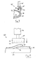
- Figures 4 and 5 are particularly directed to the compression molding process.
- the molding fixture 44 is moved via linear movement apparatus 46 toward surface 34 to engage leading end 36 and trailing end 39, under pressure, with mold section 50 in order to form joint 60 in the still molten extrudate 18.
- Molding cavity 54 imparts a predetermined cross-sectional profile to joint 60, which is preferably substantially similar to the cross-sectional profile of the remainder of extrudate 18.
- the ring member thus formed is allowed to cool to a predetermined temperature and is then removed from the turntable 30.
- the turntable 30 is then recycled back to a predetermined position at the extrusion station 10.
- repositioning turntable 30 is accomplished by another rotation step.
Landscapes
- Engineering & Computer Science (AREA)
- Mechanical Engineering (AREA)
- Casting Or Compression Moulding Of Plastics Or The Like (AREA)
- Extrusion Moulding Of Plastics Or The Like (AREA)
Abstract
Description
- The invention generally relates to a process for forming an annular member comprising one or more thermoplastics. The annular member thus formed is particularly useful in pipe seal applications.
- In applications such as pipe seals, the governing specifications require the material to have a low compression set. Thermoset rubbers (TSR), those vulcanized or cross-linked after molding, have typically been used. Thermoplastics and thermoplastic elastomers have been proposed to replace TSR in many applications, particularly dynamically vulcanized thermoplastic elastomers, e.g., thermoplastic vulcanizates (TPV), A TPV typically consists of a vulcanized rubber particle phase dispersed within a continuous thermoplastic phase. Those currently proposed to meet typical pipe seal specifications are grades having a hardness of approximately 45-65 Shore A. To form a ring member from an extruded profile, there must necessarily be a joint or weld. The softer grades of TPVs do not always heat weld in a welding process with adequate strength as compared to a vulcanized splice in a TSR. This is often due in soft TPVs to the higher content of dispersed rubber phase and decreased content of hard thermoplastic. In addition, the joint or weld, can provide a leak path both during pressure and vacuum testing of the piping system and its subsequent use if the weld joint is not effective.
- Seals for small pipe diameters (e.g., 12 inch diameter) can be prepared by injection molding which avoids a need for a weld. However, seals having large diameters (e.g., greater than 12 inch diameter) or with lower unit volume are not typically suitable for injection molding processes due to high tooling and equipment costs. Instead, extruded seal material profiles are cut to length, formed into a ring, and then welded or joined through a thermal welding process or vulcanized splicing. Thus there exists a need in the art for an improved process to provide larger diameter pipe seals that can be fabricated from thermoplastic materials.
- In the thermal welding process excess thermoplastic extends upon joining of the ends thus causing leaking or substandard seal performance. Thus, the heat-welded joint of thermoplastic, particularly thermoplastic elastomer, has substandard performance with respect to the thermoset rubber seals that utilize a vulcanized splice with little excess. Thus TPE seals have been inadequate for more demanding applications such as sewer pipes due to weld quality and long-term performance. The present invention is directed to overcoming these and other problems.
- In accordance with an exemplary form of the present invention there is provided a process comprising extruding a strip of molten thermoplastic material through an extrusion die wherein the strip has a generally continuous cross-sectional profile and a leading end and a trailing end. Subsequent to extruding the strip and without substantially cooling the strip, the leading end and the trailing end are joined to form a joint there between by compression molding of the leading and trailing ends at a temperature sufficiently high to allow plastic flow in the area of the joint. The extrusion process imparts a predetermined cross-sectional profile to the extrudate. During the compression molding, the mold imparts the predetermined cross-sectional profile to the joint section.
- In exemplary embodiments, the thermoplastic material may comprise one or more of engineering thermoplastics, thermoplastic elastomers (TPE), and mixtures thereof. Particular suitable thermoplastic materials will include dynamically vulcanized TPE, or thermoplastic vulcanizate (TPV). Particularly suitable are the polyolefin TPV compounds comprising at least one non-crosslinked polyolefin thermoplastic phase and at least one cross-linked polyolefin rubber phase. Other suitable thermoplastics include the thermoplastic polyolefins (TPO) without a cross-linked phase, such as homopolymers of ethylene or propylene, or copolymers with each together, and copolymers of ethylene or propylene, or together, with other polymerizable C4-C8 comonomers; styrene block copolymers (SBC) and blends of such copolymers, both those considered thermoplastic and those exhibiting the properties of thermoplastic elastomers; and blends of polyolefins, or blends of one or more of them, with SBC copolymers. Thermoplastic polyurethane elastomers will also be suitable, alone or in blends.
- An exemplary process comprises extruding the thermoplastic material (or even one or more coextruded thermoplastics, optionally with the TPE) at an elevated temperature onto a movable fixture; interrupting the extruding of the material; moving the fixture so as to bring the leading end of the extrudate to a predetermined relationship to the trailing end; and, before said trailing end cools to a predetermined cooled temperature, engaging the leading end and the trailing end in a mold under pressure to form a joint section in order to form an annular member of the thermoplastic material. In this exemplary process a shaped extrusion die imparts a predetermined profile to the extrudate and the mold imparts the predetermined profile in the joint section. The annular member thus formed may be adapted to provide a generally fluid tight seal between adjacent fluid carrying conduits. The use of a coextruded outer thermoplastic plus an inner thermoplastic elastomer provides for a stiffer profile, more dimensionally stable shape, even at higher use temperatures, while retaining the sealing capabilities of the thermoplastic elastomer.
- In some embodiments the movable fixture may include a rotating planar surface onto which the extrudate is positioned. The planar surface may be rotated to bring the leading end of the extrudate into engaged relationship with the trailing end. Alternately, the movable fixture may include a rotatable molding cylinder having an outer deposit-receiving surface. The extrudate can be directed onto the surface as the molding cylinder rotates so that the leading end of the extrudate may be brought into engaged relationship with the trailing end.
- An exemplary apparatus includes an extruder having an exit die for forming a polymer extrudate having a leading end, an implement for severing later extruded polymer extrudate to create a trailing end, a rotatable fixture having a deposit-receiving surface for receiving the polymer extrudate and a compression molding mechanism. The rotatable fixture is operable to return the leading end of extrudate to a position in contact with the trailing end. The compression molding mechanism is adapted to cooperate with the rotatable fixture to form a joint in the polymer extrudate at a position where the leading end and trailing end are in contact.
- By using a thermoplastic extruder, and specialized downstream equipment, continuous seals can be produced with superior spliced joints, automatically, and in-line with the extrusion process.
- One advantage of exemplary forms of the present invention is that enhanced performance TPVs can replace TSRs to form large diameter pipe seals.
- Another advantage of exemplary embodiments is that the splicing operation is completed without the time or energy expenditures required in vulcanization of TSRs.
- Another advantage of exemplary embodiments is that the quality of the spliced joint is improved as compared to heat welding because the operation is performed on the molten TPV prior to significant cooling. The joints may exhibit superior strength and minimal flashing as compared to standard hot plate welding on TPVs.
- Another advantage of exemplary embodiments is the reduced tooling and equipment costs as compared to an injection molding process. For example, one extrusion die may be capable of producing seals for several sizes of pipe.
- Still other advantages of exemplary embodiments of the present invention will be apparent to those having skill in the art upon a reading and understanding of the specification.
- Figure 1 is a schematic perspective view of an exemplary embodiment of an apparatus for carrying out an exemplary process for producing an annular seal using a rotatable turntable;
- Figure 2 is a partial schematic view of a compression molding station prior to a molding step;
- Figure 3 is a partial schematic view of an alternate exemplary embodiment of a compression molding station;
- Figure 4 is a partial front view illustrating an exemplary compression molding station prior to a molding step;
- Figure 5 is a partial front view illustrating an exemplary compression molding station after a molding step;
- Figure 6 is a partial front view of the alternate exemplary embodiment of an extrusion station; shown in Figure 1;
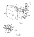
- Figure 7 is a schematic perspective view of an exemplary embodiment of an apparatus utilizing a rotating cylinder to receive the molten extrudate;
- Figure 8 is a partial schematic perspective view of an apparatus showing an alternate embodiment of a compression molding station.
- Thermoplastic Elastomer (TPE): a diverse family of rubber like materials that, unlike conventional vulcanized rubbers, can be processed and recycled like thermoplastic materials. Typical examples include blends of "hard" crystalline, semi-crystalline, or glassy polymers (for instance those having a Tm greater than about 110°C or Tg greater than about 60°C, as measured by differential scanning calorimetry (DSC), more preferably with amorphous or low-crystallinity polymers (Tm less than about 90°C or Tg less than 60°C by DSC). Examples of hard polymers include the non-polar and polar engineering resins such as polypropylene, polyethylene, polyamide, polycarbonate, and polyester resins. The "soft" polymers include most rubbers, particularly the non-polar olefm rubbers, for hard polyolefins, and polar rubbers for polar hard resins. Non-polar rubbers include ethylenepropylene rubber, very low density polyethylene copolymers comprising C4 to C8 α-olefin or vinyl aromatic comonomers, butyl rubber, natural rubber, styrene-butadiene rubber butadiene rubber, butadiene rubber and the like. Compatibilizing block copolymers and/or functionalized polymers are often used to improve overall engineering properties where incompatibility may exist as in blends of apolar and polar polymers.
- Thermoplastic Vulcanizate (TPV): a thermoplastic elastomer with a chemically crosslinked rubbery phase, produced by dynamic vulcanization; TPVs provide functional performance and properties similar to conventional thermoset rubber products, but can be processed with the speed, efficiency and economy of thermoplastics; in addition to simpler processing, principal advantages of TPVs compared to thermoset rubber products include easier recycling of scrap and closer, more economical control of dimensions and product quality.
- Dynamic Vulcanization: the process of intimate melt mixing a thermoplastic polymer and a suitable vulcanizable rubbery polymer with a crosslinking or vulcanization agent to generate a thermoplastic elastomer with a chemically crosslinked rubbery phase, resulting in properties closer to those of a thermoset rubber when compared to the same uncrosslinked composition. Thermoplastic vulcanizates and processes for preparing them are well known in the art, see for example,
US patents, 4,130,535 ,4,311,628 ,4,594,390 , and5,672,660 , and "Dynamically Vulcanized Thermoplastic Elastomers", S. Abdou-Sabet, et al, Rubber Chemistry and Technology, Vol. 69, No. 3, July-August 1996, and references cited therein. - Styrene Block Copolymers: the SBC thermoplastics and thermoplastic elastomers useful in the invention are block copolymers of styrene/conjugated diene/styrene, with the conjugated diene optionally being fully or partially hydrogenated, or mixtures thereof. Generally this block copolymer may contain 10 to 50 weight %, more preferably 25 to 35 weight %, of styrene and 90 to 50 weight %, more preferably 75 to 35 weight % of the conjugated diene, based on said block copolymer. Most preferred, however, is a block copolymer which contains 28 to 35 weight % of styrene and 68 to 72 weight % of the conjugated diene. The conjugated diene is selected from butadiene, isoprene or mixtures thereof. Block copolymers of the styrene/conjugated diene/styrene type are SBS, SIS, SIBS, SEBS and SEPS, and SEEPS block copolymers.
- These block copolymers useful are known in the art, and are further described in
Canadian Pat. No. 2,193,264 and inInternational Pat. Applications WO 96/20248 WO 96/23823 WO 98/12240 WO 99/46330 - Thermoplastic Polyurethane: another suitable thermoplastic is thermoplastic polyurethane (TPU) prepared from substantially difunctional ingredients, i.e. organic diisocyanates and components being substantially difunctional in active hydrogen containing groups, particularly those that have at least one major Tg of less than 60°C. However, often minor proportions of ingredients with functionalities higher than two may be employed. This is particularly true when using extenders such as glycerol, trimethylol propane, and the like. Any of the TPU materials known in the art within this description can be employed within the scope of the present invention. The preferred TPU is a polymer prepared from a mixture comprising at least one organic diisocyanate, at least one polymeric diol and at least one difunctional extender. The TPU can be prepared by prepolymer, quasi-prepolymer or one-shot methods commonly used in the art, see
International Pat. Application No. WO 01 10950 - Figures 1-5 illustrate a first exemplary embodiment of an
apparatus 10 including anextrusion station 11 wherein athermoplastic extruder 12 receives raw material from afeed hopper 14 in order to formextrudate 18.Extrudate 18 may be chosen from the general class of thermoplastic elastomers (TPE) or cam be a thermoplastic vulcanizate (TPV) produced by dynamic vulcanization. To meet engineering objectives of tight fit and effective sealing, the thermoplastic material in the sealing portion of the profile typically will have a Shore D hardness of not greater than 50. The thermoplastic elastomeric materials utilized in an exemplary form of the present invention include various grades of Santoprene® thermoplastic elastomers available from Advanced Elastomer Systems, Akron, Ohio. Exemplary grade designations include Santoprene® 101-55; Santoprene® 101-73; and Santoprene® 103-50. - In this exemplary embodiment, molten material flows through an
extrusion head 22 and is positioned onto amovable fixture 26 having arotatable turntable 30.Turntable 30 includes a generally planar deposit-receiving surface-34. In this exemplary embodiment, the positioning and rotational speed of theturntable 30 is controlled relative to the flow from theextrusion head 22 to provide a continuous extrudate having a leadingend 36. In this exemplary embodiment,apparatus 10 further includes an implement such as knife (not shown) for interrupting the flow from theextrusion head 22 to create a trailingend 39 ofextrudate 18. - The extrusion process imparts a predetermined cross-sectional profile to
extrudate 18. In this exemplary embodiment, themolten extrudate 18 is able to generally retain a predetermined three-dimensional shape during the extrusion process while turntable 3 0 is rotated. - As best seen in Figure 1,
apparatus 10 of this exemplary embodiment further includes acompression molding station 40 for in-line compression molding of still-moltenextrudate 18. In this exemplary embodiment, thecompression molding station 40 includes amolding fixture 44 that is movable toward and away fromplanar surface 34 through operation of alinear movement mechanism 46 such as a hydraulic mechanism, a pneumatic mechanism, or other suitable means.Movable fixture 44 includes amold section 50 having amolding cavity 54 adapted to mate with the formedextrudate 18, although thecavity 54 may be slightly undersized, from 5% to 10%, for adequate compression. - With reference again to Figure 1, an exemplary process utilizes a
rotatable turntable 30 to supportmolten extrudate 18. Theturntable 30 is positioned under anextrusion head 22 in order to receive material as it exits theextruder 12. In a controlled manner, the material, including leadingend 36, is extruded onto theturntable 30 as it rotates in the direction ofarrow 103. After a predetermined amount of material has been extruded, an implement or knife is employed to create trailingend 39. The amount of material extruded is sufficient to bring trailingend 39 into close proximity or overlapping relationship to leadingend 36 upon rotation ofturntable 30 substantially 360E. After theturntable 30 completes a rotation, a molding region 55 (shown in phantom) of theturntable 30, which supports leadingend 36 and trailingend 39, is positioned at thecompression molding station 40. In this exemplary process,extrudate 18 is not removed fromturntable 30 as the leading and trailing ends are joined. In the exemplary process, themolten extrudate 18 is dimensionally stable even at temperatures above the melt temperature of the material. Thus, the predetermined cross-sectional profile of theextrudate 18 is retained during this exemplary process. - In this exemplary embodiment, when sufficient volume of
extrudate 18 is deposited ontosurface 34 so that trailingend 39meets leading end 36,turntable 30 is repositioned to placemolding region 55 at thecompression molding station 40 by rotating turntable 30 a predetermined indexed arc α. - Figures 4 and 5 are particularly directed to the compression molding process. At the
compression molding station 40, themolding fixture 44 is moved vialinear movement apparatus 46 towardsurface 34 to engage leadingend 36 and trailingend 39, under pressure, withmold section 50 in order to form joint 60 in the still moltenextrudate 18.Molding cavity 54 imparts a predetermined cross-sectional profile to joint 60, which is preferably substantially similar to the cross-sectional profile of the remainder ofextrudate 18. - The ring member thus formed is allowed to cool to a predetermined temperature and is then removed from the
turntable 30. Theturntable 30 is then recycled back to a predetermined position at theextrusion station 10. In this exemplary process, repositioningturntable 30 is accomplished by another rotation step. - In a second exemplary embodiment, positioning the
turntable 30 at acompression molding station 40 comprises a physical transfer of theturntable 30. In this exemplary process, anotherturntable 30 may be positioned under theextrusion head 22 to receive a fresh extrudate stream while the first extrudate stream undergoes the compression molding step. The use of more than oneturntable 30 may be preferable to obtain a more efficient production system. - For ease of processing, the flow of extrudate may be only momentarily interrupted in order to create trailing
end 39 andposition turntable 30 at the compression molding station. Thus, in another exemplary embodiment, illustrated in Figure 6,apparatus 10 may include a melt diverting system generally denoted 62. - In this exemplary embodiment, melt diverting
system 62 includes a conveyor 66 for directing the flow ofextrudate 18. The melt diverting system includes an implement such as knife 38' for momentary interruption of the flow of material in order to create a trailingend 39 ofextrudate 18. After a brief interruption, the flow of material is resumed. Because there may be a time lag until aturntable 30 is properly positioned to receive the extrudate, excess material is diverted to acollection site 70. In the exemplary embodiment, the conveyor 66 is movable such that excess material carried thereon may be diverted away fromturntable 30 tocollection site 70. In the exemplary embodiment, the chosen material may be readily recycled from thecollection site 70. -
Knife 72 and conveyer 66 operate in coordinated movement withextruder 12 andturntable 30 to deliver a predetermined amount of material to surface 34. After the predetermined volume of material has been delivered, themolding region 55 ofturntable 30 is positioned atcompression molding station 40 while the flow of material is diverted. When aturntable 30 is again positioned at theextrusion station 11, the flow of material is interrupted again, in order to create a leading end of fresh extrudate to be deposited ontosurface 34. Conveyor 66 is re-positioned in order to deliver extrudate to surface 34, and the process is repeated. Additional fixturing (not shown) may be employed to accurately guide theextrudate 18 into a desired position. The nature of the exemplary thermoplastic elastomeric material allows for the collection and in-line recycling of the scrap or flash created during the exemplary processes. Thus, the overall scrap rate can be minimized. - Various configurations of a molding station may be utilized. For example, Figure 3 illustrates an alternate embodiment of molding station 40'. In this exemplary embodiment, molding fixture 44' includes a
shaping pinion roller 86 having a rotatable shapedsurface 88 adapted to mate with the formedextrudate 18. As in a previously described embodiment, the molding fixture 44' is movable toward and away fromsurface 34 via operation of linear movement apparatus 46',Pinion roller 86 operates to engage leadingend 36 and trailingend 39 to form a joint in the still-moltenextrudate 18. - In another exemplary embodiment, illustrated in Figure 7, an
apparatus 150 for producing annular thermoplastic members includes anextrusion station 154 and acompression molding station 156. Theextrusion station 154 includes athermoplastic extruder 162 that utilizes an exit die 170 to form and shape anextrudate 168 having aleading end 172 in a manner similar to those described in previous embodiments. An implement orknife 174 may be positioned adjacent exit die 170 to interrupt the extrudate stream and create trailingend 176. - A
rotatable molding cylinder 180 includes a deposit-receivingouter surface 182 operable to receive and supportmolten extrudate 168. Theouter surface 182 may include one or more locating and shaping grooves 184.Molding cylinder 180 may further include vacuum holes 185 formed in groove 184 for enhanced retention of the extrudate on the rotating cylinder. - In this exemplary embodiment, the
molding cylinder 180 is further adapted for reciprocal movement along itslongitudinal axis 186. In this embodiment, a firstcompression molding station 156 is spaced from theextrusion station 154 such that reciprocal movement of themolding cylinder 180 is operable to move theextrudate 168 from theextrusion station 154 to thecompression molding station 156 without removal of the extrudate 168 from the deposit-receivingouter surface 182. In this exemplary embodiment,cylinder 180 may receive a plurality of extrudate streams to be compression molded. Thus, reciprocal movement ofcylinder 180 must be sufficient to allow each extrudate stream to be positioned at the firstcompression molding station 156. Alternately, additional compression molding stations may be utilized to accommodate a plurality of extrudate streams. - The first
compression molding station 156 includes amold section 188 movable toward and away frommolding cylinder 180 in a radial direction via operation of a linear movement apparatus in a manner similar to that described in previous embodiments.Mold section 188 includes amolding cavity 189 adapted to mate with the formedextrudate 168, although thecavity 189 may be slightly undersized, from 5% to 10%, for adequate compression of theextrudate 168 into themold section 188. - An alternate embodiment of a compression molding station 156' is illustrated in Figure 8. In this exemplary embodiment, a shaping
pinion roller 200 is movable toward and away frommolding cylinder 180 in a radial direction. As in previously described embodiments, shapingpinion roller 200 includes a profiledsurface 202 adapted to mate with the formedextrudate 168.Pinion roller 200 is operable to form a joint inextrudate 168 at a position where theleading end 172 meets trailingend 176. In other exemplary embodiments, shapingpinion roller 200 may be continuously engaged with theextrudate 168 ascylinder 180 rotates to provide a three-dimensional feature to the formedextrudate 168 in addition to forming a joint. - The nature of the thermoplastic elastomeric material allows for this type of automated production. The molten thermoplastic elastomer, unlike most thermoplastics, retains its shaped profile during the extrusion process. In the compression molding process, the molten extrudate can be readily molded to form the joint, without the need for a vulcanization step as necessary for thermoset material. Additionally, the formed ring member does not have to cool for an extended period of time before it can be removed from the molding cylinder.
- An alternate embodiment of a
rotatable molding cylinder 180 replaces this fixture with the fluid carrying conduit or pipe. In this embodiment the conduit is rotated under the extruder exit die along a longitudinal axis so that the leading end engages the pipe in the final installed location, typically on the spigot end, and the subsequent extrudate is wrapped around the conduit until the trailing end is severed and positioned in proximity to the leading end. A shaping roller may be utilized to further improve thermal adhesion between the extrudate and the conduit surface. The leading and trailing ends of the extrudate are then compression molded or roll formed as described in previous embodiments. The seal is then allowed to cool in place, where the natural shrinkage improves seal to conduit adhesion and provides an additional interference fit. - In yet another exemplary embodiment a second thermoplastic material may be utilized to improve adhesion between the extrudate and the conduit. This process includes an apparatus adapted for co-extrusion. A first extruder applies a first material to exit die 22 while a second extruder applies a second material to the same extrusion die. The extrusion die is adapted with specially designed flow channels that allow both materials to exit the die in a laminar flow so that the extrudate appears as a single part with two distinctive materials of similar or varied physical properties and/or chemical properties in different cross-sectional areas. This embodiment comprising multiple materials (2 or more) formed into an annular member, joined at the ends, and cooled may be practiced with each of the embodiments described.
- Typical designs for gaskets that are currently used in this field are described in the following US patent Nos.; 6,336,640, and 6,550,775B2. These patents reference gasket having one or more materials as previously described
- In the described exemplary embodiments, the compression-molding process occurs while the extrudate is still in a molten state. In an exemplary process, the extrudate temperature should be in excess of 375°F (190°C), for typical polyolefin-based TPV materials, to prevent visible flow lines. It has been discovered that the temperature of the mold section affects the finished quality of the joint section. Thus, using anodized aluminum tooling, the mold section should be utilized at a temperature less than about 250°F (120°C) to prevent sticking and deformation of the extrudate. Sufficient pressure should be added to the mold section to minimize a parting line. Successful trials were accomplished using a minimum of 1500 PSI (10.3 mPa) on the projected area of the splice. The mold section can be moved away from the formed ring member after sufficient cooling. It has been found that cooling to 180°F (80°C) provides ample cooling.
- Thus the exemplary apparatus and processes for forming an annular pipe seal achieve the above stated objectives.
- Having described the features, discoveries and principles of the invention, the manner in which it is constructed and operated, and the advantages and useful results attained; the new and useful structures, devices, elements, arrangements, parts, combinations, systems, equipment, operations, methods and relationships are set forth in the appended claims.
Claims (18)
- A process comprising:(a) extruding a strip of molten thermoplastic material through an extrusion die wherein the strip has a generally continuous cross-sectional profile and a leading end and a trailing end; and,(b) subsequent to (a) and without substantially cooling the strip, joining the leading end and the trailing end to form a joint therebetween by compression molding of the leading and trailing ends at a temperature sufficiently high to allow plastic flow in the area of the joint.
- The process of claim 1 wherein in (a) the thermoplastic material comprises at least one selected from a group including engineering thermoplastics, thermoplastic elastomers (TPE), and mixtures thereof.
- The process of claim 2 wherein in (a) the thermoplastic material comprises a thermoplastic vulcanizate (TPV).
- The process of claim 1 wherein in (a) the thermoplastic material has a Shore D hardness of not greater than 50 when the thermoplastic material is at room temperature.
- The process of claim 1 wherein in (b) the cross-sectional profile of the strip is substantially maintained in the joint.
- A process comprising:(a) extruding a thermoplastic elastomeric material onto a movable fixture to provide an extrudate having a leading end, wherein the extrudate exits an extruder die at an elevated predetermined temperature;(b) interrupting the extruding of the material to produce a trailing end of the extrudate;(c) moving the fixture during at least a portion of (a) so as to bring the leading end of the extrudate to a predetermined relationship to the trailing end; and,(d) before the extrudate cools to a predetermined cooled temperature, engaging the leading end and the trailing end in a mold under pressure to form a joint, wherein an annular member of the material is formed.
- The process of claim 6 wherein (a) includes utilizing a shaped die to impart a predetermined profile to the extrudate.
- The process of claim 7 wherein (d) includes utilizing the mold to impart the predetermined profile to the joint.
- The process of claim 6 wherein the annular member in (d) has a minimum inner diameter of at least about 12 inches.
- The process of claim 6 further comprising:(e) sufficiently cooling the extrudate to predetermined temperature.
- The process of claim 6 wherein (c) includes rotating a deposit-receiving surface in supporting connection with the movable fixture substantially 360< about an axis.
- The process of claim 6 wherein the movable fixture comprises a substantially planar deposit-receiving surface that rotates in a horizontal plane and wherein (a) includes directing the extrudate onto the planar surface while the planar surface rotates.
- The process of claim 6 wherein the movable fixture comprises a rotatable cylinder having an outer deposit-receiving surface and wherein (a) includes directing the extrudate onto the outer surface while the cylinder rotates.
- The process of claim 6 wherein the extrudate is comprised of one or more thermoplastic elastomers, thermoplastic vulcanizates, or engineered thermoplastics, or any combination thereof, as in a typical co-extrusion process.
- The process of claim 7 wherein in (a), the thermoplastic material is capable of substantially retaining the predetermined cross-sectional profile while in a molten state.
- The process of claim 6 further comprising:(e) positioning the annular member in intermediate relation of two fluid carrying conduits.
- The process of claim 6 wherein in (a) the movable fixture is a conduit adapted to carry fluids.
- An apparatus comprising:an extruder having an exit die for forming a polymer extrudate having a leading end;an implement for severing later extruded polymer extrudate to create a trailing end;a rotatable fixture having a deposit-receiving surface for receiving the polymer extrudate, wherein the rotatable fixture is operable to return the leading end of extrudate to a position in contact with the trailing end; and,a compression molding mechanism, wherein the compression molding mechanism is adapted to cooperate with the rotatable fixture to form a joint in the polymer extrudate at a position where the leading end and trailing end are in contact.
Priority Applications (1)
| Application Number | Priority Date | Filing Date | Title |
|---|---|---|---|
| EP20060007175 EP1870229A1 (en) | 2006-06-23 | 2006-06-23 | Process and apparatus for pipe seal manufacture |
Applications Claiming Priority (1)
| Application Number | Priority Date | Filing Date | Title |
|---|---|---|---|
| EP20060007175 EP1870229A1 (en) | 2006-06-23 | 2006-06-23 | Process and apparatus for pipe seal manufacture |
Publications (1)
| Publication Number | Publication Date |
|---|---|
| EP1870229A1 true EP1870229A1 (en) | 2007-12-26 |
Family
ID=38719705
Family Applications (1)
| Application Number | Title | Priority Date | Filing Date |
|---|---|---|---|
| EP20060007175 Withdrawn EP1870229A1 (en) | 2006-06-23 | 2006-06-23 | Process and apparatus for pipe seal manufacture |
Country Status (1)
| Country | Link |
|---|---|
| EP (1) | EP1870229A1 (en) |
Cited By (1)
| Publication number | Priority date | Publication date | Assignee | Title |
|---|---|---|---|---|
| CN103991221A (en) * | 2014-05-07 | 2014-08-20 | 北京化工大学 | Mould-less large-caliber PVC pipe dynamic molding method and device |
Citations (8)
| Publication number | Priority date | Publication date | Assignee | Title |
|---|---|---|---|---|
| GB793529A (en) * | 1954-11-04 | 1958-04-16 | Angus George Co Ltd | Improvements in and relating to the manufacture of rubber or like rings |
| US3026569A (en) * | 1959-02-16 | 1962-03-27 | Philip B Keller | Method of fabricating omicron-rings |
| GB1486608A (en) * | 1972-11-13 | 1977-09-21 | Spherex Inc | Ring forming machine |
| EP0414298A1 (en) * | 1989-08-23 | 1991-02-27 | Hovap International B.V. | Method for manufacturing an O-ring |
| US5173234A (en) * | 1990-08-03 | 1992-12-22 | Eropol Finance Et Developpement | Process and automatic machine for manufacture of calibrated rings from an extrudate |
| US5297949A (en) * | 1990-12-29 | 1994-03-29 | Bridgestone Corporation | Annular member forming apparatus |
| DE19616911A1 (en) * | 1995-04-18 | 1996-10-24 | M C M S N C Di Marchesi Filast | Continuous production of O-rings |
| US6689297B1 (en) * | 2000-02-22 | 2004-02-10 | Uchiyama Manufacturing Corp. | Method of manufacturing magnetic rubber ring |
-
2006
- 2006-06-23 EP EP20060007175 patent/EP1870229A1/en not_active Withdrawn
Patent Citations (8)
| Publication number | Priority date | Publication date | Assignee | Title |
|---|---|---|---|---|
| GB793529A (en) * | 1954-11-04 | 1958-04-16 | Angus George Co Ltd | Improvements in and relating to the manufacture of rubber or like rings |
| US3026569A (en) * | 1959-02-16 | 1962-03-27 | Philip B Keller | Method of fabricating omicron-rings |
| GB1486608A (en) * | 1972-11-13 | 1977-09-21 | Spherex Inc | Ring forming machine |
| EP0414298A1 (en) * | 1989-08-23 | 1991-02-27 | Hovap International B.V. | Method for manufacturing an O-ring |
| US5173234A (en) * | 1990-08-03 | 1992-12-22 | Eropol Finance Et Developpement | Process and automatic machine for manufacture of calibrated rings from an extrudate |
| US5297949A (en) * | 1990-12-29 | 1994-03-29 | Bridgestone Corporation | Annular member forming apparatus |
| DE19616911A1 (en) * | 1995-04-18 | 1996-10-24 | M C M S N C Di Marchesi Filast | Continuous production of O-rings |
| US6689297B1 (en) * | 2000-02-22 | 2004-02-10 | Uchiyama Manufacturing Corp. | Method of manufacturing magnetic rubber ring |
Cited By (2)
| Publication number | Priority date | Publication date | Assignee | Title |
|---|---|---|---|---|
| CN103991221A (en) * | 2014-05-07 | 2014-08-20 | 北京化工大学 | Mould-less large-caliber PVC pipe dynamic molding method and device |
| CN103991221B (en) * | 2014-05-07 | 2016-03-23 | 北京化工大学 | A kind of without mould heavy caliber PVC dynamic molding method and device |
Similar Documents
| Publication | Publication Date | Title |
|---|---|---|
| EP0851805B1 (en) | Method and apparatus for manufacturing of oriented polymeric products | |
| EP2403703B1 (en) | Multilayer, heat-shrinkable film comprising a plurality of microlayers and method for its fabrication | |
| US8579624B2 (en) | Systems and methods for making multi-wall corrugated pipe | |
| US7094310B2 (en) | Method for joining high-pressure composite pipes | |
| CN103249546B (en) | Adhesive tape, its manufacture method and airtyred manufacture method | |
| US6951336B2 (en) | Method of manufacturing a boot seal | |
| US7951316B2 (en) | Process for pipe seal manufacture | |
| CN103249548B (en) | Adhesive strip, its manufacturing method and manufacturing method of pneumatic tire | |
| EP1147004B1 (en) | Spiral wound pipe and a method for manufacturing the same | |
| US5862591A (en) | Method for manufacturing paint rollers | |
| US4442147A (en) | Oriented multi-layer films having a different orientation distribution between layers | |
| EP1870229A1 (en) | Process and apparatus for pipe seal manufacture | |
| AU2003255806A1 (en) | Plastics pipe | |
| US6682689B1 (en) | Flexible plastic article and method of manufacturing the same | |
| CN222538321U (en) | Welding device for HDPE inner rib winding pipe faucet | |
| AU2013251239B2 (en) | Multilayer, heat-shrinkable film comprising a plurality of microlayers and method for its fabrication | |
| JP2007203725A (en) | Circular resin tube joint and manufacturing process thereof | |
| EP1827792A1 (en) | Plastics pipe | |
| JP2005003171A (en) | Pressure-resistant hose |
Legal Events
| Date | Code | Title | Description |
|---|---|---|---|
| PUAI | Public reference made under article 153(3) epc to a published international application that has entered the european phase |
Free format text: ORIGINAL CODE: 0009012 |
|
| AK | Designated contracting states |
Kind code of ref document: A1 Designated state(s): AT BE BG CH CY CZ DE DK EE ES FI FR GB GR HU IE IS IT LI LT LU LV MC NL PL PT RO SE SI SK TR |
|
| AX | Request for extension of the european patent |
Extension state: AL BA HR MK YU |
|
| 17P | Request for examination filed |
Effective date: 20080524 |
|
| 17Q | First examination report despatched |
Effective date: 20080627 |
|
| AKX | Designation fees paid |
Designated state(s): DE ES FR GB |
|
| RAP1 | Party data changed (applicant data changed or rights of an application transferred) |
Owner name: EXXONMOBIL CHEMICAL PATENTS INC. |
|
| STAA | Information on the status of an ep patent application or granted ep patent |
Free format text: STATUS: THE APPLICATION IS DEEMED TO BE WITHDRAWN |
|
| 18D | Application deemed to be withdrawn |
Effective date: 20100105 |