EP1869322B1 - Oil-less compressor with seal-dust protection - Google Patents
Oil-less compressor with seal-dust protection Download PDFInfo
- Publication number
- EP1869322B1 EP1869322B1 EP05714646A EP05714646A EP1869322B1 EP 1869322 B1 EP1869322 B1 EP 1869322B1 EP 05714646 A EP05714646 A EP 05714646A EP 05714646 A EP05714646 A EP 05714646A EP 1869322 B1 EP1869322 B1 EP 1869322B1
- Authority
- EP
- European Patent Office
- Prior art keywords
- gas
- dust
- compressor
- control enclosure
- piston
- Prior art date
- Legal status (The legal status is an assumption and is not a legal conclusion. Google has not performed a legal analysis and makes no representation as to the accuracy of the status listed.)
- Expired - Lifetime
Links
Images



Classifications
-
- F—MECHANICAL ENGINEERING; LIGHTING; HEATING; WEAPONS; BLASTING
- F04—POSITIVE - DISPLACEMENT MACHINES FOR LIQUIDS; PUMPS FOR LIQUIDS OR ELASTIC FLUIDS
- F04B—POSITIVE-DISPLACEMENT MACHINES FOR LIQUIDS; PUMPS
- F04B25/00—Multi-stage pumps
- F04B25/005—Multi-stage pumps with two cylinders
-
- F—MECHANICAL ENGINEERING; LIGHTING; HEATING; WEAPONS; BLASTING
- F04—POSITIVE - DISPLACEMENT MACHINES FOR LIQUIDS; PUMPS FOR LIQUIDS OR ELASTIC FLUIDS
- F04B—POSITIVE-DISPLACEMENT MACHINES FOR LIQUIDS; PUMPS
- F04B25/00—Multi-stage pumps
-
- F—MECHANICAL ENGINEERING; LIGHTING; HEATING; WEAPONS; BLASTING
- F04—POSITIVE - DISPLACEMENT MACHINES FOR LIQUIDS; PUMPS FOR LIQUIDS OR ELASTIC FLUIDS
- F04B—POSITIVE-DISPLACEMENT MACHINES FOR LIQUIDS; PUMPS
- F04B39/00—Component parts, details, or accessories, of pumps or pumping systems specially adapted for elastic fluids, not otherwise provided for in, or of interest apart from, groups F04B25/00 - F04B37/00
- F04B39/0005—Component parts, details, or accessories, of pumps or pumping systems specially adapted for elastic fluids, not otherwise provided for in, or of interest apart from, groups F04B25/00 - F04B37/00 adaptations of pistons
-
- F—MECHANICAL ENGINEERING; LIGHTING; HEATING; WEAPONS; BLASTING
- F04—POSITIVE - DISPLACEMENT MACHINES FOR LIQUIDS; PUMPS FOR LIQUIDS OR ELASTIC FLUIDS
- F04B—POSITIVE-DISPLACEMENT MACHINES FOR LIQUIDS; PUMPS
- F04B39/00—Component parts, details, or accessories, of pumps or pumping systems specially adapted for elastic fluids, not otherwise provided for in, or of interest apart from, groups F04B25/00 - F04B37/00
- F04B39/0005—Component parts, details, or accessories, of pumps or pumping systems specially adapted for elastic fluids, not otherwise provided for in, or of interest apart from, groups F04B25/00 - F04B37/00 adaptations of pistons
- F04B39/0022—Component parts, details, or accessories, of pumps or pumping systems specially adapted for elastic fluids, not otherwise provided for in, or of interest apart from, groups F04B25/00 - F04B37/00 adaptations of pistons piston rods
-
- F—MECHANICAL ENGINEERING; LIGHTING; HEATING; WEAPONS; BLASTING
- F04—POSITIVE - DISPLACEMENT MACHINES FOR LIQUIDS; PUMPS FOR LIQUIDS OR ELASTIC FLUIDS
- F04B—POSITIVE-DISPLACEMENT MACHINES FOR LIQUIDS; PUMPS
- F04B39/00—Component parts, details, or accessories, of pumps or pumping systems specially adapted for elastic fluids, not otherwise provided for in, or of interest apart from, groups F04B25/00 - F04B37/00
- F04B39/04—Measures to avoid lubricant contaminating the pumped fluid
-
- F—MECHANICAL ENGINEERING; LIGHTING; HEATING; WEAPONS; BLASTING
- F04—POSITIVE - DISPLACEMENT MACHINES FOR LIQUIDS; PUMPS FOR LIQUIDS OR ELASTIC FLUIDS
- F04B—POSITIVE-DISPLACEMENT MACHINES FOR LIQUIDS; PUMPS
- F04B39/00—Component parts, details, or accessories, of pumps or pumping systems specially adapted for elastic fluids, not otherwise provided for in, or of interest apart from, groups F04B25/00 - F04B37/00
- F04B39/12—Casings; Cylinders; Cylinder heads; Fluid connections
-
- F—MECHANICAL ENGINEERING; LIGHTING; HEATING; WEAPONS; BLASTING
- F04—POSITIVE - DISPLACEMENT MACHINES FOR LIQUIDS; PUMPS FOR LIQUIDS OR ELASTIC FLUIDS
- F04B—POSITIVE-DISPLACEMENT MACHINES FOR LIQUIDS; PUMPS
- F04B53/00—Component parts, details or accessories not provided for in, or of interest apart from, groups F04B1/00 - F04B23/00 or F04B39/00 - F04B47/00
- F04B53/14—Pistons, piston-rods or piston-rod connections
- F04B53/144—Adaptation of piston-rods
- F04B53/146—Piston-rod guiding arrangements
Definitions
- This invention relates to an oil-less compressor that delivers high-pressure gas to a storage reservoir.
- it relates to a home refuelling appliance for refuelling motor vehicles that operate on gaseus fuels. Compressor able to do so are disclosed for example in US 4 889, 039 in AU 680 8381 A , in EP-A-0883054 and in EP-A-0340 150 ;
- the invention relates to an oil-less compressor, and particularly to a multi-stage compressor for refuelling gas-powered vehicles. Accordingly, the invention in one aspect addresses a gas compressor assembly which comprise
- a gas compressor having at least a first stage with at least one cylinder with dry seals having a piston mounted therein with a piston rod connected to the piston and extending into a crank case cavity;
- crank mechanism which is located in the crank case cavity connected to operate the piston rod
- said compressor assembly further comprising a dust control enclosure having a sidewall through which the piston rod passes, said dust control enclosure forming a barrier between the dry seals and the crank mechanism that substantially limits dust from the dry seals accessing the crank mechanism.
- the dust control enclosure is preferably in the form of a sleeve which when fitted forms a cap with penetrations through its sidewalls which have dust-excluding seals through which the rod(s) pass.
- Such seals are preferably in the form of washer-like rings made of felt-like material. This arrangement effectively confines dust generated by deterioration of the sealing rings to remain on the piston and cylinder sides of the dust control enclosure.
- the low pressure gas supply inlet delivers gas to the crank case cavity
- the first stage of the compressor takes its intake of gas to be compressed from the crank case cavity on the piston side of the dust control enclosure.
- the compressor unit of the invention in a preferred variant is a multi-stage compressor, e.g. a four stage compressor having pairs of opposed, linearly reciprocating, pistons.
- the pistons are preferably driven in pairs by Scotch yokes as a specific type of crank mechanism, actuated by a shaft extending from the crank case cavity to a motor. According to this system, the piston rods move in a straight line.
- the dust control enclosure is installed within the crank case portion of the compressor.
- This enclosure preferably made of substantially rigid polymeric plastic material, may be in the form of a sleeve which, when mounted on the bearing housing flange, forms a cap or cup that surrounds the crank mechanism.
- This cap has sidewalls through which the piston rods pass as they extend inwardly to connect to the Scotch yokes. It is at these penetrations through the sidewalls of this enclosure that dust-excluding seals in the form of washers made of felt-like material are preferably installed.
- Figure 1 is a pictorial representation of a gaseous fuel motor vehicle parked in a garage having a home refuelling appliance according to the invention mounted on its inner wall.
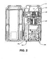
- FIG. 2 is a schematic depiction of the principal components of the appliance with the front shroud/cover of the housing removed, including the unitary motor/compressor assembly, its casing, control circuits, other support elements including various sensors.
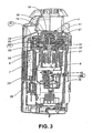
- Figure 3 is a cross-sectional side view of the appliance of Figures 1 and 2 exposing the compressor and motor assembly and showing the location of the dust control enclosure in cross-section in relation to the first and third stage cylinders in the compressor.
- Figure 4 is an enlarged view of Figure 3 showing the compressor in detail.
- Figure 5 is perspective view depicting the dust control enclosure with holes to allow penetration by piston rods within the motor/compressor assembly of Figure 3 .
- Figure 6 is a top view of the enclosure of Figure 5 .
- Figure 7 is a cross-sectional side view of the enclosure of Figure 6 .
- FIG. 1 the home refueling appliance 1 is shown mounted on a garage wall with the high-pressure discharge hose 2 connected to a car, the inlet hose 3 connected to a source of gas, and the electrical cord 4 plugged into a standard household receptacle.
- the compressor unit of the invention in a preferred variant is a multi-stage compressor 5, e.g. a four stage compressor 5 having pairs of opposed, linearly reciprocating, pistons 50, shown in Figures.
- the pistons 50 are preferably driven in pairs by Scotch yokes 51 actuated by a drive/crank shaft 52 extending from the motor 27 into the crank case cavity 14.
- the compressor unit is provided with a low-pressure gas supply inlet 59 for connection to a source of gas and a high-pressure gas discharge outlet 70 for delivery of compressed gas to an external reservoir.
- Figure 3 schematically depicts the unit operating in compression mode.
- Gas 6 which has been fed into the interior crank case volume 14 of the casing 26 is drawn into the first 28 of a series of four compression stages of compressor 5.
- the gas 6, which typically has a pressure ofbetween about 1,38 to 3,45 kPa (0.2 and 0.5 psi), is drawn into the interior casing volume 14 by the suction created by the first compression stage 28.
- the gas 6 On leaving the first stage 28, the gas 6 passes through a desiccant bed 7 contained within an absorption chamber 29. Upon exiting the absorption chamber 29, the dried gas continues into the condenser 30 which is, at this stage, passive. Exiting the condenser 30, the gas 6 proceeds to the next, second stage 32 of the compressor 5 for completion of the compression process.
- the compressor 5, motor 27 and motor control circuitry 45 are all located within the casing 26, (counting the compressor block as part of the casing).
- the main logic controller 46 fed power from a power supply, is able to activate the motor 27, and govern its speed in the variable speed version, through motor control circuitry 45.
- the wall of the casing 26 acts as heat sink for the heat produced by the motor controller circuitry 45 and as a shield against outgoing electromagnetic emissions.
- the speed of the electric motor 27 may be controlled to avoid natural resonant frequencies arising from its mechanical components that would otherwise increase the noise and vibration generated by the unit.
- the pistons 50 mounted in their respective cylinders 54 are each provided with dry seals 53.
- the pistons 50 are connected each by a piston rod 57 to the Scotch yoke crank mechanism 51 located in the crank case cavity 14.
- the pistonrods 50 pass through the sidewall 55 of the dust control enclosure 56 which forms a barrier between the dry seals 53 on the pistons 50 and the crank mechanism 51, excluding dust from the dry seals 53 accessing the crank mechanism 51.
- the dust control enclosure 56 as shown in Figures 5, 6, and 7 is in the form of a sleeve fitted to the bearings support 58, shown in Figures 3 and 4 , to form a cap installed within the crank case portion 14 of the compressor 5.
- This enclosure 56 is provided with penetrations 60 through its sidewalls 55 which have dust-excluding dust seals 71.
- the rods 57 pass through these dust seals 71 as they extend inwardly to connect to the crank mechanism 51.
- Such dust seals 71 are preferably in the form of washers made of felt-like material that are compatible with the compressor environment.
- the dust control enclosure 56 is preferably made of semi-rigid polymeric plastic material with similar compatibility.
- the dust control enclosure 56 as shown is mounted on the bearing housing flange.
- the low-pressure gas supply inlet 59 delivers gas 6 to the crank case cavity 14 where the Scotch yoke mechanism 51 is present.
- the first stage 28 of the compressor 5 takes its intake of gas 6 to be compressed from the crank case cavity 14 on the piston side of the dust control enclosure 56 through first cylinder supply valve 72 fitted within the piston 50. Because gas 6 enters the first stage 28 of the compressor 5 by flowing first through the crank case cavity 14 within the region of the dust control enclosure and then through a partially constricted passageway 80 linking both sides of the dust control enclosure, and because the first stage 28 takes its intake of gas 6 to be compressed from the region outside the dust control enclosure 56, a pressure differential generally exists within the compressor unit between these two regions.
- the cool and dust-free arriving gas flow coming from the low-pressure gas supply inlet 59 passes first around the crank mechanism 51 components in the crank case volume 14 contained by the dust enclosure to provide cooling. This is advantageous as the Scotch Yoke drives generate significant heat due to bearing friction.
- the dust enclosure 56 minimizes the presence of dust in the crank case cavity by reason of the barrier that it provides and the general pressure differential that is maintained.
- the Scotch yoke mechanism 51 is able to serve two opposed cylinders located in a common plane. When four cylinders are employed, the second pair of cylinders is in a second plane. Accordingly, the further penetrations or openings 60A in the dust control enclosure 56 needed to accommodate the further piston rods 50 are off-set from the first pair of openings 60.
Landscapes
- Engineering & Computer Science (AREA)
- Mechanical Engineering (AREA)
- General Engineering & Computer Science (AREA)
- Compressor (AREA)
- Compressors, Vaccum Pumps And Other Relevant Systems (AREA)
Description
- This invention relates to an oil-less compressor that delivers high-pressure gas to a storage reservoir. In particular, it relates to a home refuelling appliance for refuelling motor vehicles that operate on gaseus fuels. Compressor able to do so are disclosed for example in
US 4 889, 039 inAU 680 8381 A EP-A-0883054 and inEP-A-0340 150 ; - A number of applications exist which require gas to be compressed to a high-pressure, e.g. 20; 68 MPa (3000 psi), without introducing traces of lubricants into the compressed gas.
AU 6808381 - In the past, natural gas fuelled motor vehicles have generally been refuelled at commercial refuelling facilities. Provision has also existed for home refuelling systems that produce compressed natural gas from the low-pressure natural gas lines available at residential sites. Particularly in the case of a home refuelling appliance, it is desirable for such units to be installed for long term, unattended operation. An oil-less compressor provided with features of the invention would be especially suited for both of these applications, but the invention has general application wherever an oil-less compressor having dry seals that produce contaminating dust is employed.
- . In a high pressure oil-free gas compressor compression is preferably maintained through dry seals based upon the use of polymeric ring materials. A disadvantage of this system is that the polymeric ring materials generate dust which is potentially damaging to the bearings in the compressor mechanism. A need exists for a system which will reduce the wear and damage that can arise within the compressor from the formulation of such dust. This invention addresses that need.
- The invention in its general from will first be described, and then its implentation in terms of specific embodiments will be detailed with reference to the drawings following hereafter. These embodiments are intended to demonstrate the principle of the invention, and the manner of its implementation. The invention in its broadest and more specific forms will then be further described, and defined, in each of the individual claims, which conclude this Specification.
- The invention relates to an oil-less compressor, and particularly to a multi-stage compressor for refuelling gas-powered vehicles. Accordingly, the invention in one aspect addresses a gas compressor assembly which comprise
- a) a gas compressor having at least a first stage with at least one cylinder with dry seals having a piston mounted therein with a piston rod connected to the piston and extending into a crank case cavity;
- b) a crank mechanism which is located in the crank case cavity connected to operate the piston rod; and
- c) a low-pressure gas supply inlet for connection to a source of gas and delivery of gas to said first stage; and
- d) a high-pressure gas discharge outlet for delivery of compressed gas to an external reservoir;
- said compressor assembly further comprising a dust control enclosure having a sidewall through which the piston rod passes, said dust control enclosure forming a barrier between the dry seals and the crank mechanism that substantially limits dust from the dry seals accessing the crank mechanism.
- The dust control enclosure is preferably in the form of a sleeve which when fitted forms a cap with penetrations through its sidewalls which have dust-excluding seals through which the rod(s) pass. Such seals are preferably in the form of washer-like rings made of felt-like material. This arrangement effectively confines dust generated by deterioration of the sealing rings to remain on the piston and cylinder sides of the dust control enclosure.
- According to a further variant of the invention, the low pressure gas supply inlet delivers gas to the crank case cavity, and the first stage of the compressor takes its intake of gas to be compressed from the crank case cavity on the piston side of the dust control enclosure.
- The compressor unit of the invention in a preferred variant is a multi-stage compressor, e.g. a four stage compressor having pairs of opposed, linearly reciprocating, pistons. The pistons are preferably driven in pairs by Scotch yokes as a specific type of crank mechanism, actuated by a shaft extending from the crank case cavity to a motor. According to this system, the piston rods move in a straight line.
- In order to minimize the extent to which ring dust can enter the bearings of the Scotch yokes, the dust control enclosure is installed within the crank case portion of the compressor. This enclosure, preferably made of substantially rigid polymeric plastic material, may be in the form of a sleeve which, when mounted on the bearing housing flange, forms a cap or cup that surrounds the crank mechanism. This cap has sidewalls through which the piston rods pass as they extend inwardly to connect to the Scotch yokes. It is at these penetrations through the sidewalls of this enclosure that dust-excluding seals in the form of washers made of felt-like material are preferably installed.
- Because line gas enters the first stage of the compressor by flowing first through the crank case cavity before following a gas flow path to the piston side of the dust control enclosure, and because the first stage takes its intake of gas to be compressed from the region outside the dust control enclosure, a pressure differential exists within the compressor unit. The region around the Scotch yokes benefits from an overpressure of up to nearly the line gas pressure e.g 1,38 to 3,45 kPa (0.2 to 0.5 psi) with respect to the pressure outside the dust control enclosure, on the piston seals side where ring dust forms. Thus a continuous flow of dust-free incoming gas sweeps through this higher-pressure region before entering the first compression stage. This flow operates to help exclude dust from entering the region around the Scotch yokes.
- The foregoing summarizes the principal features of the invention and some of its optional aspects. The invention may be further understood by the description of the preferred embodiments, in conjunction with the drawings, which now follow.
-
Figure 1 is a pictorial representation of a gaseous fuel motor vehicle parked in a garage having a home refuelling appliance according to the invention mounted on its inner wall. -
Figure 2 is a schematic depiction of the principal components of the appliance with the front shroud/cover of the housing removed, including the unitary motor/compressor assembly, its casing, control circuits, other support elements including various sensors. -
Figure 3 is a cross-sectional side view of the appliance ofFigures 1 and2 exposing the compressor and motor assembly and showing the location of the dust control enclosure in cross-section in relation to the first and third stage cylinders in the compressor. -
Figure 4 is an enlarged view ofFigure 3 showing the compressor in detail. -
Figure 5 is perspective view depicting the dust control enclosure with holes to allow penetration by piston rods within the motor/compressor assembly ofFigure 3 . -
Figure 6 is a top view of the enclosure ofFigure 5 . -
Figure 7 is a cross-sectional side view of the enclosure ofFigure 6 . - In
Figure 1 the home refueling appliance 1 is shown mounted on a garage wall with the high-pressure discharge hose 2 connected to a car, the inlet hose 3 connected to a source of gas, and theelectrical cord 4 plugged into a standard household receptacle. - The compressor unit of the invention in a preferred variant is a
multi-stage compressor 5, e.g. a fourstage compressor 5 having pairs of opposed, linearly reciprocating,pistons 50, shown in Figures. Thepistons 50 are preferably driven in pairs by Scotch yokes 51 actuated by a drive/crank shaft 52 extending from themotor 27 into thecrank case cavity 14. The compressor unit is provided with a low-pressuregas supply inlet 59 for connection to a source of gas and a high-pressuregas discharge outlet 70 for delivery of compressed gas to an external reservoir. -
Figure 3 schematically depicts the unit operating in compression mode.Gas 6 which has been fed into the interiorcrank case volume 14 of thecasing 26 is drawn into the first 28 of a series of four compression stages ofcompressor 5. Thegas 6, which typically has a pressure ofbetween about 1,38 to 3,45 kPa (0.2 and 0.5 psi), is drawn into theinterior casing volume 14 by the suction created by thefirst compression stage 28. - On leaving the
first stage 28, thegas 6 passes through adesiccant bed 7 contained within anabsorption chamber 29. Upon exiting theabsorption chamber 29, the dried gas continues into thecondenser 30 which is, at this stage, passive. Exiting thecondenser 30, thegas 6 proceeds to the next,second stage 32 of thecompressor 5 for completion of the compression process. - The
compressor 5,motor 27 andmotor control circuitry 45 are all located within thecasing 26, (counting the compressor block as part of the casing). Themain logic controller 46, fed power from a power supply, is able to activate themotor 27, and govern its speed in the variable speed version, throughmotor control circuitry 45. The wall of thecasing 26 acts as heat sink for the heat produced by themotor controller circuitry 45 and as a shield against outgoing electromagnetic emissions. - On start-up, low motor speeds are adopted to reduce otherwise high start-up current drains on the electrical supply system. This enables the unit to operate off of a standard household voltage, e.g. 110-120 volt, moderately fused electrical supply system. After start-up, the initial process of compression can be effected with a high motor speed. Once higher pressures have been established in the motor vehicle fuel reservoir, motor speed is reduced in order to moderate ring wear and limit power consumption. This procedure is especially suited to
oil-less compressors 5 as the wear rate of the sealing rings 53 within thecompressor cylinders 54 of such units increases when the compressor system is operated at high speed against a high-back pressure. - Additionally, the speed of the
electric motor 27 may be controlled to avoid natural resonant frequencies arising from its mechanical components that would otherwise increase the noise and vibration generated by the unit. - As shown in
Figures 3 and4 , thepistons 50 mounted in theirrespective cylinders 54 are each provided withdry seals 53. Thepistons 50 are connected each by apiston rod 57 to the Scotch yoke crankmechanism 51 located in thecrank case cavity 14. Thepistonrods 50 pass through thesidewall 55 of thedust control enclosure 56 which forms a barrier between thedry seals 53 on thepistons 50 and thecrank mechanism 51, excluding dust from thedry seals 53 accessing thecrank mechanism 51. - The
dust control enclosure 56 as shown inFigures 5, 6, and 7 is in the form of a sleeve fitted to the bearings support 58, shown inFigures 3 and4 , to form a cap installed within thecrank case portion 14 of thecompressor 5. Thisenclosure 56 is provided withpenetrations 60 through itssidewalls 55 which have dust-excluding dust seals 71. Therods 57 pass through these dust seals 71 as they extend inwardly to connect to thecrank mechanism 51. Such dust seals 71 are preferably in the form of washers made of felt-like material that are compatible with the compressor environment. Thedust control enclosure 56 is preferably made of semi-rigid polymeric plastic material with similar compatibility. Thedust control enclosure 56 as shown is mounted on the bearing housing flange. - The low-pressure
gas supply inlet 59 deliversgas 6 to the crankcase cavity 14 where theScotch yoke mechanism 51 is present. Thefirst stage 28 of thecompressor 5 takes its intake ofgas 6 to be compressed from thecrank case cavity 14 on the piston side of thedust control enclosure 56 through firstcylinder supply valve 72 fitted within thepiston 50. Becausegas 6 enters thefirst stage 28 of thecompressor 5 by flowing first through thecrank case cavity 14 within the region of the dust control enclosure and then through a partially constrictedpassageway 80 linking both sides of the dust control enclosure, and because thefirst stage 28 takes its intake ofgas 6 to be compressed from the region outside thedust control enclosure 56, a pressure differential generally exists within the compressor unit between these two regions. Thus a continuous flow of dust-freeincoming gas 6 sweeps through this higher-pressure region of thecrank case cavity 14 before entering thefirst compression stage 28. This flow operates to help exclude piston seal dust from remaining in thecrank mechanism 51. Further gas flow to thenext stage 32 and subsequent stages occurs through sealed conduits. - Additionally, the cool and dust-free arriving gas flow coming from the low-pressure
gas supply inlet 59 passes first around thecrank mechanism 51 components in thecrank case volume 14 contained by the dust enclosure to provide cooling. This is advantageous as the Scotch Yoke drives generate significant heat due to bearing friction. - Similarly, for the
second stage 32 and further stages, ifpresent, thedust enclosure 56 minimizes the presence of dust in the crank case cavity by reason of the barrier that it provides and the general pressure differential that is maintained. - The
Scotch yoke mechanism 51 is able to serve two opposed cylinders located in a common plane. When four cylinders are employed, the second pair of cylinders is in a second plane. Accordingly, the further penetrations oropenings 60A in thedust control enclosure 56 needed to accommodate thefurther piston rods 50 are off-set from the first pair ofopenings 60. - On this basis a system is provided that protects the crank mechanism from dust arising from the dry seals.
- The foregoing has constituted a description of specific embodiments showing how the invention may be applied and put into use. These embodiments are only exemplary. The invention in its broadest, and more specific aspects, is further described and defined in the claims which now follow.
- These claims, and the language used therein, are to be understood in terms of the variants of the invention which have been described. They are not to be restricted to such variants, but are to be read as covering the full scope of the invention as is implicit within the invention and the disclosure that has been provided herein.
Claims (7)
- A gas compressor assembly comprising:a gas compressor (5) having at least a first stage (28) with at least one cylinder (54) with a piston (50) having a polymeric ring dry seals (53);characterized in that said piston (50) supports an inlet valve means (72) to connect said gas supply inlet (59) and said crank case cavity (14) to gas discharge outlet (70) through said piston (50) and in that said compressor assembly further comprising a dust fixed control enclosure (56) placed within the crank case cavity (14); said dust fixed control enclosure (56) being fixed to a support (58) to form a cup that surround the crank mechanism (51); said cup having a sidewall (55) having a penetration (60) through which the piston rod (57) passes, said dust control enclosure (56) forming a fixed barrier between the polymeric ring dry seals (53) and the crank mechanism (51) that excludes dust from the polymeric ring dry seals from accessing the crank mechanism (51).a) a piston rod (57) connected to said piston (50) and extending into a crank case cavity (14) of a casing (26);b) a crank mechanism (51) located in the crank case cavity (14) to operate said piston rod (57);c) a low pressure gas supply inlet (59) for connection to a source of gas and delivery of gas to said first stage (28); andd) a high-pressure gas discharge outlet (70) on said gas compressor for delivery of compressed gas to an external reservoir;
- A gas compressor assembly as claimed in Claim 1 wherein the low pressure gas supply inlet (59) delivers gas to the crank case cavity (14) in the region of the crank mechanism (51) on the crank shaft side of the dust control enclosure (56) and the first stage of the compressor takes its intake of gas to be compressed from the crank case cavity (14) on the piston side of the dust control enclosure (56) through a cylinder supply valve (72), there being a gas flow path extending from the region of the crank mechanism (51) to the portion of the crank case cavity (14) on the piston side of the dust control enclosure (56) whereby a pressure differential may be formed in operation across the barrier formed by the dust control enclosure.
- A gas compressor assembly as claimed in Claims 1 or 2, characterized in that the dust control enclosure (56) further comprises a dust-excluding dust seal (71) placed on said penetration (60) in said sidewall (55) and surrounding said piston rod (57).
- A gas compressor assembly as a claimed in Claim 3, characterized in that said dust seal (71) is in the form of washers comprising a felted material.
- A gas compressor assembly as claimed in any one of the preceding Claims, characterized in that the compressor is a multi-stage compressor having a piston rod (50) for each stage and penetrations (60) in the dust control enclosure (56) for each piston rod (57).
- A gas compressor assembly as claimed in Claim 5, characterized in that the crank mechanism (51) comprises two or more Scotch yokes connected to a shaft extending into the crank case cavity (14).
- A gas compressor assembly as claimd in Claim 6 wherein the compressor is a four stage compressor having pairs of opposed, linearly reciprocating, pistons (50).
Priority Applications (2)
| Application Number | Priority Date | Filing Date | Title |
|---|---|---|---|
| PL05714646T PL1869322T3 (en) | 2005-03-17 | 2005-03-18 | Oil-less compressor with seal-dust protection |
| SI200531673T SI1869322T1 (en) | 2005-03-17 | 2005-03-18 | Oil-less compressor with seal-dust protection |
Applications Claiming Priority (2)
| Application Number | Priority Date | Filing Date | Title |
|---|---|---|---|
| CA2005000395 | 2005-03-17 | ||
| PCT/CA2005/000408 WO2006096957A1 (en) | 2005-03-17 | 2005-03-18 | Oil-less compressor with seal-dust protection |
Publications (3)
| Publication Number | Publication Date |
|---|---|
| EP1869322A1 EP1869322A1 (en) | 2007-12-26 |
| EP1869322A4 EP1869322A4 (en) | 2009-11-11 |
| EP1869322B1 true EP1869322B1 (en) | 2012-11-28 |
Family
ID=36991225
Family Applications (1)
| Application Number | Title | Priority Date | Filing Date |
|---|---|---|---|
| EP05714646A Expired - Lifetime EP1869322B1 (en) | 2005-03-17 | 2005-03-18 | Oil-less compressor with seal-dust protection |
Country Status (7)
| Country | Link |
|---|---|
| US (1) | US20090214361A1 (en) |
| EP (1) | EP1869322B1 (en) |
| JP (1) | JP4856165B2 (en) |
| ES (1) | ES2399894T3 (en) |
| PL (1) | PL1869322T3 (en) |
| SI (1) | SI1869322T1 (en) |
| WO (1) | WO2006096957A1 (en) |
Families Citing this family (3)
| Publication number | Priority date | Publication date | Assignee | Title |
|---|---|---|---|---|
| US9856866B2 (en) | 2011-01-28 | 2018-01-02 | Wabtec Holding Corp. | Oil-free air compressor for rail vehicles |
| US9388801B2 (en) | 2013-03-29 | 2016-07-12 | Douglas Rietkerk | Natural gas compressor with scissor drive assembly |
| CN112196768A (en) * | 2020-11-10 | 2021-01-08 | 士商(上海)机械有限公司 | air compressor |
Family Cites Families (10)
| Publication number | Priority date | Publication date | Assignee | Title |
|---|---|---|---|---|
| US3204864A (en) * | 1963-06-03 | 1965-09-07 | Malaker Lab Inc | Compensating-pressure piston and cylinders for gas compressors and expanders |
| AU6808381A (en) * | 1975-12-24 | 1981-06-25 | Commonwealth Scientific And Industrial Research Organisation | Two-component piston ring |
| IL86201A0 (en) * | 1988-04-27 | 1988-11-15 | Ice Cryogenic Engineering Ltd | Rotary compressors |
| US4889039A (en) * | 1988-10-17 | 1989-12-26 | Miller Bernard F | Gas compressor with labyrinth sealing and active magnetic bearings |
| CH678881A5 (en) * | 1989-03-23 | 1991-11-15 | Sulzer Ag | |
| EP0833054B1 (en) * | 1996-09-26 | 2003-08-13 | Teikoku Piston Ring Co., LTd. | Compressor |
| US5957667A (en) * | 1997-05-23 | 1999-09-28 | Ballard Generation Systems Inc. | Oilless compressor with a pressurizable crankcase and motor containment vessel |
| GB2400891A (en) * | 2003-04-23 | 2004-10-27 | Boc Group Plc | Dry pump oil sump and lubricant conduits |
| US20060045768A1 (en) * | 2004-08-24 | 2006-03-02 | Fei-Tyh Chuang | Oil-less air compressor |
| DE102006042021A1 (en) * | 2006-09-07 | 2008-03-27 | BSH Bosch und Siemens Hausgeräte GmbH | Compressor with gas-bearing piston |
-
2005
- 2005-03-18 JP JP2008501119A patent/JP4856165B2/en not_active Expired - Fee Related
- 2005-03-18 SI SI200531673T patent/SI1869322T1/en unknown
- 2005-03-18 PL PL05714646T patent/PL1869322T3/en unknown
- 2005-03-18 ES ES05714646T patent/ES2399894T3/en not_active Expired - Lifetime
- 2005-03-18 EP EP05714646A patent/EP1869322B1/en not_active Expired - Lifetime
- 2005-03-18 WO PCT/CA2005/000408 patent/WO2006096957A1/en not_active Ceased
- 2005-03-18 US US11/908,718 patent/US20090214361A1/en not_active Abandoned
Also Published As
| Publication number | Publication date |
|---|---|
| WO2006096957A1 (en) | 2006-09-21 |
| SI1869322T1 (en) | 2013-04-30 |
| US20090214361A1 (en) | 2009-08-27 |
| ES2399894T3 (en) | 2013-04-04 |
| EP1869322A1 (en) | 2007-12-26 |
| JP4856165B2 (en) | 2012-01-18 |
| EP1869322A4 (en) | 2009-11-11 |
| JP2008533365A (en) | 2008-08-21 |
| PL1869322T3 (en) | 2013-05-31 |
Similar Documents
| Publication | Publication Date | Title |
|---|---|---|
| JP7500676B2 (en) | Electrically powered gas booster | |
| KR101363170B1 (en) | Motor-driven compressor | |
| US20170321671A1 (en) | Linear compressor | |
| US10968907B2 (en) | Linear compressor | |
| US10533546B2 (en) | Linear compressor | |
| CN100404857C (en) | Linear compressor | |
| US20070160483A1 (en) | Booster-type gas compressor | |
| US10280914B2 (en) | Linear compressor | |
| CN1646812A (en) | Pressure equalization system and method | |
| KR20030042751A (en) | Reciprocating compressor | |
| US20090214361A1 (en) | Oil-less compressor with seal-dust protection | |
| US20070132321A1 (en) | Linear compressor | |
| CA2600937A1 (en) | Oil-less compressor with seal-dust protection | |
| CN1218543A (en) | Suction arrangement for reciprocating hermetic compressor | |
| CN110894828B (en) | Linear compressor and control method of refrigerator | |
| CN109322830A (en) | Water lubrication compression system | |
| US20220314938A1 (en) | Compressor unit | |
| US20220220953A1 (en) | Linear compressor | |
| KR20010018433A (en) | Structure for reducing suction-noise of linear compressor | |
| KR102158879B1 (en) | Linear compressor | |
| CN1540165A (en) | hermetic compressor | |
| US10935014B2 (en) | Compressor | |
| KR20010018432A (en) | Suction muffler for linear compressor | |
| KR102075974B1 (en) | Multi-stage single type oil free reciprocating compressing apparatus | |
| KR20070075903A (en) | Linear compressor |
Legal Events
| Date | Code | Title | Description |
|---|---|---|---|
| PUAI | Public reference made under article 153(3) epc to a published international application that has entered the european phase |
Free format text: ORIGINAL CODE: 0009012 |
|
| 17P | Request for examination filed |
Effective date: 20071015 |
|
| AK | Designated contracting states |
Kind code of ref document: A1 Designated state(s): AT BE BG CH CY CZ DE DK EE ES FI FR GB GR HU IE IS IT LI LT LU MC NL PL PT RO SE SI SK TR |
|
| DAX | Request for extension of the european patent (deleted) | ||
| RIC1 | Information provided on ipc code assigned before grant |
Ipc: F04B 53/14 20060101ALI20090831BHEP Ipc: F04B 25/00 20060101ALI20090831BHEP Ipc: F04B 39/00 20060101ALI20090831BHEP Ipc: F04B 39/04 20060101AFI20060927BHEP |
|
| A4 | Supplementary search report drawn up and despatched |
Effective date: 20090904 |
|
| 17Q | First examination report despatched |
Effective date: 20101115 |
|
| RAP1 | Party data changed (applicant data changed or rights of an application transferred) |
Owner name: 2045951 ONTARIO INC. |
|
| RAP1 | Party data changed (applicant data changed or rights of an application transferred) |
Owner name: M.T.M. S.R.L. |
|
| GRAP | Despatch of communication of intention to grant a patent |
Free format text: ORIGINAL CODE: EPIDOSNIGR1 |
|
| GRAS | Grant fee paid |
Free format text: ORIGINAL CODE: EPIDOSNIGR3 |
|
| GRAA | (expected) grant |
Free format text: ORIGINAL CODE: 0009210 |
|
| AK | Designated contracting states |
Kind code of ref document: B1 Designated state(s): AT BE BG CH CY CZ DE DK EE ES FI FR GB GR HU IE IS IT LI LT LU MC NL PL PT RO SE SI SK TR |
|
| REG | Reference to a national code |
Ref country code: GB Ref legal event code: FG4D |
|
| REG | Reference to a national code |
Ref country code: CH Ref legal event code: EP |
|
| REG | Reference to a national code |
Ref country code: AT Ref legal event code: REF Ref document number: 586323 Country of ref document: AT Kind code of ref document: T Effective date: 20121215 |
|
| REG | Reference to a national code |
Ref country code: IE Ref legal event code: FG4D |
|
| REG | Reference to a national code |
Ref country code: DE Ref legal event code: R096 Ref document number: 602005037183 Country of ref document: DE Effective date: 20130124 |
|
| REG | Reference to a national code |
Ref country code: SE Ref legal event code: TRGR |
|
| REG | Reference to a national code |
Ref country code: CH Ref legal event code: NV Representative=s name: HEPP WENGER RYFFEL AG, CH |
|
| REG | Reference to a national code |
Ref country code: NL Ref legal event code: T3 |
|
| REG | Reference to a national code |
Ref country code: ES Ref legal event code: FG2A Ref document number: 2399894 Country of ref document: ES Kind code of ref document: T3 Effective date: 20130404 |
|
| REG | Reference to a national code |
Ref country code: AT Ref legal event code: MK05 Ref document number: 586323 Country of ref document: AT Kind code of ref document: T Effective date: 20121128 |
|
| REG | Reference to a national code |
Ref country code: LT Ref legal event code: MG4D |
|
| PG25 | Lapsed in a contracting state [announced via postgrant information from national office to epo] |
Ref country code: LT Free format text: LAPSE BECAUSE OF FAILURE TO SUBMIT A TRANSLATION OF THE DESCRIPTION OR TO PAY THE FEE WITHIN THE PRESCRIBED TIME-LIMIT Effective date: 20121128 Ref country code: FI Free format text: LAPSE BECAUSE OF FAILURE TO SUBMIT A TRANSLATION OF THE DESCRIPTION OR TO PAY THE FEE WITHIN THE PRESCRIBED TIME-LIMIT Effective date: 20121128 |
|
| PGFP | Annual fee paid to national office [announced via postgrant information from national office to epo] |
Ref country code: CZ Payment date: 20130313 Year of fee payment: 9 Ref country code: ES Payment date: 20130313 Year of fee payment: 9 Ref country code: FR Payment date: 20130325 Year of fee payment: 9 Ref country code: SE Payment date: 20130312 Year of fee payment: 9 Ref country code: DE Payment date: 20130314 Year of fee payment: 9 Ref country code: GB Payment date: 20130313 Year of fee payment: 9 Ref country code: CH Payment date: 20130312 Year of fee payment: 9 |
|
| REG | Reference to a national code |
Ref country code: GR Ref legal event code: EP Ref document number: 20130400384 Country of ref document: GR Effective date: 20130327 |
|
| REG | Reference to a national code |
Ref country code: SK Ref legal event code: T3 Ref document number: E 13448 Country of ref document: SK |
|
| PG25 | Lapsed in a contracting state [announced via postgrant information from national office to epo] |
Ref country code: BE Free format text: LAPSE BECAUSE OF FAILURE TO SUBMIT A TRANSLATION OF THE DESCRIPTION OR TO PAY THE FEE WITHIN THE PRESCRIBED TIME-LIMIT Effective date: 20121128 Ref country code: PT Free format text: LAPSE BECAUSE OF FAILURE TO SUBMIT A TRANSLATION OF THE DESCRIPTION OR TO PAY THE FEE WITHIN THE PRESCRIBED TIME-LIMIT Effective date: 20130328 |
|
| PGFP | Annual fee paid to national office [announced via postgrant information from national office to epo] |
Ref country code: GR Payment date: 20130319 Year of fee payment: 9 Ref country code: NL Payment date: 20130309 Year of fee payment: 9 Ref country code: SI Payment date: 20130318 Year of fee payment: 9 Ref country code: PL Payment date: 20130214 Year of fee payment: 9 Ref country code: SK Payment date: 20130307 Year of fee payment: 9 |
|
| REG | Reference to a national code |
Ref country code: PL Ref legal event code: T3 |
|
| PG25 | Lapsed in a contracting state [announced via postgrant information from national office to epo] |
Ref country code: AT Free format text: LAPSE BECAUSE OF FAILURE TO SUBMIT A TRANSLATION OF THE DESCRIPTION OR TO PAY THE FEE WITHIN THE PRESCRIBED TIME-LIMIT Effective date: 20121128 |
|
| PG25 | Lapsed in a contracting state [announced via postgrant information from national office to epo] |
Ref country code: BG Free format text: LAPSE BECAUSE OF FAILURE TO SUBMIT A TRANSLATION OF THE DESCRIPTION OR TO PAY THE FEE WITHIN THE PRESCRIBED TIME-LIMIT Effective date: 20130228 Ref country code: EE Free format text: LAPSE BECAUSE OF FAILURE TO SUBMIT A TRANSLATION OF THE DESCRIPTION OR TO PAY THE FEE WITHIN THE PRESCRIBED TIME-LIMIT Effective date: 20121128 Ref country code: DK Free format text: LAPSE BECAUSE OF FAILURE TO SUBMIT A TRANSLATION OF THE DESCRIPTION OR TO PAY THE FEE WITHIN THE PRESCRIBED TIME-LIMIT Effective date: 20121128 |
|
| REG | Reference to a national code |
Ref country code: HU Ref legal event code: AG4A Ref document number: E016381 Country of ref document: HU |
|
| PG25 | Lapsed in a contracting state [announced via postgrant information from national office to epo] |
Ref country code: RO Free format text: LAPSE BECAUSE OF FAILURE TO SUBMIT A TRANSLATION OF THE DESCRIPTION OR TO PAY THE FEE WITHIN THE PRESCRIBED TIME-LIMIT Effective date: 20121128 |
|
| PGFP | Annual fee paid to national office [announced via postgrant information from national office to epo] |
Ref country code: HU Payment date: 20130313 Year of fee payment: 9 |
|
| PLBE | No opposition filed within time limit |
Free format text: ORIGINAL CODE: 0009261 |
|
| STAA | Information on the status of an ep patent application or granted ep patent |
Free format text: STATUS: NO OPPOSITION FILED WITHIN TIME LIMIT |
|
| PG25 | Lapsed in a contracting state [announced via postgrant information from national office to epo] |
Ref country code: MC Free format text: LAPSE BECAUSE OF NON-PAYMENT OF DUE FEES Effective date: 20130331 |
|
| 26N | No opposition filed |
Effective date: 20130829 |
|
| PG25 | Lapsed in a contracting state [announced via postgrant information from national office to epo] |
Ref country code: CY Free format text: LAPSE BECAUSE OF FAILURE TO SUBMIT A TRANSLATION OF THE DESCRIPTION OR TO PAY THE FEE WITHIN THE PRESCRIBED TIME-LIMIT Effective date: 20121128 |
|
| REG | Reference to a national code |
Ref country code: DE Ref legal event code: R097 Ref document number: 602005037183 Country of ref document: DE Effective date: 20130829 |
|
| REG | Reference to a national code |
Ref country code: IE Ref legal event code: MM4A |
|
| PG25 | Lapsed in a contracting state [announced via postgrant information from national office to epo] |
Ref country code: IE Free format text: LAPSE BECAUSE OF NON-PAYMENT OF DUE FEES Effective date: 20130318 |
|
| REG | Reference to a national code |
Ref country code: DE Ref legal event code: R119 Ref document number: 602005037183 Country of ref document: DE |
|
| REG | Reference to a national code |
Ref country code: NL Ref legal event code: V1 Effective date: 20141001 |
|
| PG25 | Lapsed in a contracting state [announced via postgrant information from national office to epo] |
Ref country code: CZ Free format text: LAPSE BECAUSE OF NON-PAYMENT OF DUE FEES Effective date: 20140318 |
|
| REG | Reference to a national code |
Ref country code: CH Ref legal event code: PL |
|
| REG | Reference to a national code |
Ref country code: SE Ref legal event code: EUG |
|
| GBPC | Gb: european patent ceased through non-payment of renewal fee |
Effective date: 20140318 |
|
| REG | Reference to a national code |
Ref country code: GR Ref legal event code: ML Ref document number: 20130400384 Country of ref document: GR Effective date: 20141002 |
|
| PG25 | Lapsed in a contracting state [announced via postgrant information from national office to epo] |
Ref country code: SE Free format text: LAPSE BECAUSE OF NON-PAYMENT OF DUE FEES Effective date: 20140319 |
|
| REG | Reference to a national code |
Ref country code: SK Ref legal event code: MM4A Ref document number: E 13448 Country of ref document: SK Effective date: 20140318 |
|
| REG | Reference to a national code |
Ref country code: FR Ref legal event code: ST Effective date: 20141128 |
|
| REG | Reference to a national code |
Ref country code: SI Ref legal event code: KO00 Effective date: 20141104 |
|
| REG | Reference to a national code |
Ref country code: DE Ref legal event code: R119 Ref document number: 602005037183 Country of ref document: DE Effective date: 20141001 |
|
| PG25 | Lapsed in a contracting state [announced via postgrant information from national office to epo] |
Ref country code: DE Free format text: LAPSE BECAUSE OF NON-PAYMENT OF DUE FEES Effective date: 20141001 Ref country code: FR Free format text: LAPSE BECAUSE OF NON-PAYMENT OF DUE FEES Effective date: 20140331 Ref country code: GR Free format text: LAPSE BECAUSE OF NON-PAYMENT OF DUE FEES Effective date: 20141002 Ref country code: SK Free format text: LAPSE BECAUSE OF NON-PAYMENT OF DUE FEES Effective date: 20140318 Ref country code: LI Free format text: LAPSE BECAUSE OF NON-PAYMENT OF DUE FEES Effective date: 20140331 Ref country code: GB Free format text: LAPSE BECAUSE OF NON-PAYMENT OF DUE FEES Effective date: 20140318 Ref country code: CH Free format text: LAPSE BECAUSE OF NON-PAYMENT OF DUE FEES Effective date: 20140331 |
|
| PG25 | Lapsed in a contracting state [announced via postgrant information from national office to epo] |
Ref country code: NL Free format text: LAPSE BECAUSE OF NON-PAYMENT OF DUE FEES Effective date: 20141001 Ref country code: SI Free format text: LAPSE BECAUSE OF NON-PAYMENT OF DUE FEES Effective date: 20140319 Ref country code: HU Free format text: LAPSE BECAUSE OF NON-PAYMENT OF DUE FEES Effective date: 20140319 |
|
| PG25 | Lapsed in a contracting state [announced via postgrant information from national office to epo] |
Ref country code: IT Free format text: LAPSE BECAUSE OF NON-PAYMENT OF DUE FEES Effective date: 20140318 |
|
| REG | Reference to a national code |
Ref country code: ES Ref legal event code: FD2A Effective date: 20150507 |
|
| PG25 | Lapsed in a contracting state [announced via postgrant information from national office to epo] |
Ref country code: PL Free format text: LAPSE BECAUSE OF NON-PAYMENT OF DUE FEES Effective date: 20140318 |
|
| REG | Reference to a national code |
Ref country code: PL Ref legal event code: LAPE |
|
| PG25 | Lapsed in a contracting state [announced via postgrant information from national office to epo] |
Ref country code: LU Free format text: LAPSE BECAUSE OF NON-PAYMENT OF DUE FEES Effective date: 20130318 Ref country code: ES Free format text: LAPSE BECAUSE OF NON-PAYMENT OF DUE FEES Effective date: 20140319 |
|
| PG25 | Lapsed in a contracting state [announced via postgrant information from national office to epo] |
Ref country code: IS Free format text: LAPSE BECAUSE OF FAILURE TO SUBMIT A TRANSLATION OF THE DESCRIPTION OR TO PAY THE FEE WITHIN THE PRESCRIBED TIME-LIMIT Effective date: 20121128 |
|
| PG25 | Lapsed in a contracting state [announced via postgrant information from national office to epo] |
Ref country code: TR Free format text: LAPSE BECAUSE OF NON-PAYMENT OF DUE FEES Effective date: 20140318 |