EP1867919A1 - Planar lighting device - Google Patents
Planar lighting device Download PDFInfo
- Publication number
- EP1867919A1 EP1867919A1 EP05806808A EP05806808A EP1867919A1 EP 1867919 A1 EP1867919 A1 EP 1867919A1 EP 05806808 A EP05806808 A EP 05806808A EP 05806808 A EP05806808 A EP 05806808A EP 1867919 A1 EP1867919 A1 EP 1867919A1
- Authority
- EP
- European Patent Office
- Prior art keywords
- light source
- point
- lighting device
- circuit board
- heat radiation
- Prior art date
- Legal status (The legal status is an assumption and is not a legal conclusion. Google has not performed a legal analysis and makes no representation as to the accuracy of the status listed.)
- Withdrawn
Links
- 239000000945 filler Substances 0.000 claims abstract description 47
- 230000005855 radiation Effects 0.000 claims abstract description 44
- 238000003860 storage Methods 0.000 abstract description 2
- 238000005429 filling process Methods 0.000 description 8
- 238000000034 method Methods 0.000 description 7
- 239000000853 adhesive Substances 0.000 description 6
- 230000001070 adhesive effect Effects 0.000 description 6
- 239000004973 liquid crystal related substance Substances 0.000 description 4
- 239000002390 adhesive tape Substances 0.000 description 3
- 238000006073 displacement reaction Methods 0.000 description 3
- 238000001035 drying Methods 0.000 description 3
- 238000003754 machining Methods 0.000 description 3
- 238000004519 manufacturing process Methods 0.000 description 3
- 239000007769 metal material Substances 0.000 description 3
- 229910052782 aluminium Inorganic materials 0.000 description 2
- XAGFODPZIPBFFR-UHFFFAOYSA-N aluminium Chemical compound [Al] XAGFODPZIPBFFR-UHFFFAOYSA-N 0.000 description 2
- 230000015572 biosynthetic process Effects 0.000 description 2
- 230000000149 penetrating effect Effects 0.000 description 2
- 230000002093 peripheral effect Effects 0.000 description 2
- 150000003377 silicon compounds Chemical class 0.000 description 2
- 239000004925 Acrylic resin Substances 0.000 description 1
- 229920000178 Acrylic resin Polymers 0.000 description 1
- 239000004642 Polyimide Substances 0.000 description 1
- 238000004026 adhesive bonding Methods 0.000 description 1
- 230000006866 deterioration Effects 0.000 description 1
- 230000000694 effects Effects 0.000 description 1
- 230000020169 heat generation Effects 0.000 description 1
- 238000005286 illumination Methods 0.000 description 1
- 238000001746 injection moulding Methods 0.000 description 1
- 238000007726 management method Methods 0.000 description 1
- 229910052751 metal Inorganic materials 0.000 description 1
- 239000002184 metal Substances 0.000 description 1
- 229920005668 polycarbonate resin Polymers 0.000 description 1
- 239000004431 polycarbonate resin Substances 0.000 description 1
- 229920001721 polyimide Polymers 0.000 description 1
- 239000011347 resin Substances 0.000 description 1
- 229920005989 resin Polymers 0.000 description 1
- 239000000758 substrate Substances 0.000 description 1
Images




Classifications
-
- F—MECHANICAL ENGINEERING; LIGHTING; HEATING; WEAPONS; BLASTING
- F21—LIGHTING
- F21V—FUNCTIONAL FEATURES OR DETAILS OF LIGHTING DEVICES OR SYSTEMS THEREOF; STRUCTURAL COMBINATIONS OF LIGHTING DEVICES WITH OTHER ARTICLES, NOT OTHERWISE PROVIDED FOR
- F21V29/00—Protecting lighting devices from thermal damage; Cooling or heating arrangements specially adapted for lighting devices or systems
- F21V29/85—Protecting lighting devices from thermal damage; Cooling or heating arrangements specially adapted for lighting devices or systems characterised by the material
-
- G—PHYSICS
- G02—OPTICS
- G02B—OPTICAL ELEMENTS, SYSTEMS OR APPARATUS
- G02B6/00—Light guides; Structural details of arrangements comprising light guides and other optical elements, e.g. couplings
- G02B6/0001—Light guides; Structural details of arrangements comprising light guides and other optical elements, e.g. couplings specially adapted for lighting devices or systems
- G02B6/0011—Light guides; Structural details of arrangements comprising light guides and other optical elements, e.g. couplings specially adapted for lighting devices or systems the light guides being planar or of plate-like form
- G02B6/0081—Mechanical or electrical aspects of the light guide and light source in the lighting device peculiar to the adaptation to planar light guides, e.g. concerning packaging
- G02B6/0085—Means for removing heat created by the light source from the package
-
- F—MECHANICAL ENGINEERING; LIGHTING; HEATING; WEAPONS; BLASTING
- F21—LIGHTING
- F21S—NON-PORTABLE LIGHTING DEVICES; SYSTEMS THEREOF; VEHICLE LIGHTING DEVICES SPECIALLY ADAPTED FOR VEHICLE EXTERIORS
- F21S45/00—Arrangements within vehicle lighting devices specially adapted for vehicle exteriors, for purposes other than emission or distribution of light
- F21S45/40—Cooling of lighting devices
- F21S45/47—Passive cooling, e.g. using fins, thermal conductive elements or openings
-
- F—MECHANICAL ENGINEERING; LIGHTING; HEATING; WEAPONS; BLASTING
- F21—LIGHTING
- F21V—FUNCTIONAL FEATURES OR DETAILS OF LIGHTING DEVICES OR SYSTEMS THEREOF; STRUCTURAL COMBINATIONS OF LIGHTING DEVICES WITH OTHER ARTICLES, NOT OTHERWISE PROVIDED FOR
- F21V29/00—Protecting lighting devices from thermal damage; Cooling or heating arrangements specially adapted for lighting devices or systems
- F21V29/50—Cooling arrangements
- F21V29/70—Cooling arrangements characterised by passive heat-dissipating elements, e.g. heat-sinks
- F21V29/74—Cooling arrangements characterised by passive heat-dissipating elements, e.g. heat-sinks with fins or blades
-
- F—MECHANICAL ENGINEERING; LIGHTING; HEATING; WEAPONS; BLASTING
- F21—LIGHTING
- F21Y—INDEXING SCHEME ASSOCIATED WITH SUBCLASSES F21K, F21L, F21S and F21V, RELATING TO THE FORM OR THE KIND OF THE LIGHT SOURCES OR OF THE COLOUR OF THE LIGHT EMITTED
- F21Y2115/00—Light-generating elements of semiconductor light sources
- F21Y2115/10—Light-emitting diodes [LED]
-
- G—PHYSICS
- G02—OPTICS
- G02F—OPTICAL DEVICES OR ARRANGEMENTS FOR THE CONTROL OF LIGHT BY MODIFICATION OF THE OPTICAL PROPERTIES OF THE MEDIA OF THE ELEMENTS INVOLVED THEREIN; NON-LINEAR OPTICS; FREQUENCY-CHANGING OF LIGHT; OPTICAL LOGIC ELEMENTS; OPTICAL ANALOGUE/DIGITAL CONVERTERS
- G02F1/00—Devices or arrangements for the control of the intensity, colour, phase, polarisation or direction of light arriving from an independent light source, e.g. switching, gating or modulating; Non-linear optics
- G02F1/01—Devices or arrangements for the control of the intensity, colour, phase, polarisation or direction of light arriving from an independent light source, e.g. switching, gating or modulating; Non-linear optics for the control of the intensity, phase, polarisation or colour
- G02F1/13—Devices or arrangements for the control of the intensity, colour, phase, polarisation or direction of light arriving from an independent light source, e.g. switching, gating or modulating; Non-linear optics for the control of the intensity, phase, polarisation or colour based on liquid crystals, e.g. single liquid crystal display cells
- G02F1/133—Constructional arrangements; Operation of liquid crystal cells; Circuit arrangements
- G02F1/1333—Constructional arrangements; Manufacturing methods
- G02F1/1335—Structural association of cells with optical devices, e.g. polarisers or reflectors
- G02F1/1336—Illuminating devices
- G02F1/133628—Illuminating devices with cooling means
Definitions
- the present invention relates to a side-light-type planar lighting device and particularly to a planar lighting device used as illuminating means of a liquid crystal display device.
- a side-light-type planar lighting device in which a primary light source is arranged on a side end face of a light guide plate is widely used (hereinafter, the side end face on which the primary light source is arranged is referred to as an incoming light face).
- a cold cathode lamp has been used but currently, a point-like light source such as a white LED, which is more excellent in handling performance, is easier to reduce the size thereof and more excellent in impact resistance than a cold cathode lamp (hereinafter simply referred to as an LED) is used in many cases.
- FIG. 4 shows views illustrating a configuration example of such a planar lighting device, in which Fig. 4(a) is a top view and Fig. 4(b) is a side view.
- the fourth comprises a light guide plate 102, an LED 103 mounted on a circuit board 104 and arranged on a side end face of the light guide plate 102, and a radiator plate 105 made of a planar portion 105a and a side wall 105b, the light guide plate 102 being mounted on the planar portion 105a of the radiator plate 105, and the circuit board 104 on which the LED 103 is mounted is fixed to the side wall 105b so that heat generated from the LED 103 is efficiently radiated by the radiator plate 105.
- filling of the filler 106 for heat radiation is carried out by methods in which the filler 106 for heat radiation is applied with a dispenser or the like to a corresponding spot on the back face side of the LED 103 mounting position or the side wall 105b of the radiator plate 105 in the circuit board 104 and then, the circuit board 104 and the radiator plate 105 are fixed to each other using a double-sided adhesive tape or the like, not shown, or in which a through hole (not shown) is provided in advance at a predetermined spot of the radiator plate 105 and after the circuit board 104 on which the LED 103 is mounted and the radiator plate 105 are fixed together, the filler 106 for heat radiation is filled through the through hole and the like.
- a planar lighting device As an example of formation of the through hole in the radiator plate 105, as shown in a sectional view in Fig. 5, such a planar lighting device is proposed in which a through hole 116 is formed penetrating through both a radiator plate 115 made of a metal flat plate and a circuit board 114 on which an LED 113 is mounted, and a light source portion is provided by filling an adhesive filler 117 with high heat conductivity into the through hole 116 (See Patent Document 1, for example).
- Patent Document 1 describes that the light source portion is manufactured by a series of processes in which the circuit board 114 is bonded and fixed to the radiator plate 115 with an adhesive 118, the through hole 116 penetrating through the radiator plate 115 and the circuit board 114 is drilled and then, the LED 113 is mounted on the circuit board 114 and then, an adhesive filler 117 is filled into the through hole 116 and dried and solidified.
- Patent Document 1 Japanese Unexamined Patent Application Publication No. 2002-162626 (claim 1, claim 3, Figs. 1 and 2)
- the filler 106 for heat radiation in the filling process of the filler 106 for heat radiation, when the circuit board 104 onto which the filler 106 for heat radiation is applied or the radiator plate 105 is temporarily stored by a subsequent process, the filler 106 for heat radiation can easily transfer and adhere to another place and moreover, particularly when the filler 106 for heat radiation is applied on the side wall 105b of the radiator plate 105, there is a problem relating to workability in that control of an appropriate application amount is difficult.
- the radiator plate 105 lacks a portion immediately below the LED 103, which is the central portion of heat generation, there is a problem that radiation efficiency is lowered.
- the portion immediately below the LED 113 is made of the adhesive filler 117 with higher heat conductivity than the circuit substrate 114 so that the radiation characteristic is improved.
- this does not mean that the radiator plate 115 is present on the back face of the adhesive filler 117, and there is room for improvement in utilization of the radiation characteristic of the radiator plate 115.
- the radiator plate 115 has a simple flat-plane shape, and if this configuration is applied to the radiator plate 105 configured in an L-shape provided with the planar portion 105a and the side wall 105b as shown in Fig. 4, it becomes extremely difficult to carry out the above-mentioned series of manufacturing processes, which might incur deterioration of workability and increase manufacturing costs.
- the planar lighting device in Patent Document 1 no special measures are taken to cope with displacement of the point-like light source caused by heat expansion of the light guide plate.
- the present invention was made in view of the above problems and an object thereof is to provide a planar lighting device enabling improved workability of a filling process of filler for heat radiation and can achieve higher brightness by efficiently radiating heat generated from a point-like light source.
- a planar lighting device provided with a light guide plate and a point-like light source arranged on a side end face of the light guide plate, comprises a radiator plate made of a bottom portion and a side wall, a circuit board on which the point-like light source is mounted is fixed along the side wall, and at a position corresponding to the point-like light source in the side wall, a recess for holding a filler for heat radiation is formed.
- the recess portion for holding the filler for heat radiation is formed at a position corresponding to the point-like light source in the side wall of the radiator plate, an appropriate application amount of the filler for heat radiation can be determined easily by discriminating the application amount according to a volume of the recess portion, and since the filler for heat radiation after application is accommodated and held in the recess portion, the radiator plate can be easily managed and stored without transfer or adhesion to another place, which contributes to improvement of workability in the filling process of the filler for heat radiation.
- the recess portion to be a reservoir portion for the filler for heat radiation, a filler of a type having considerable fluidity and not requiring drying and solidifying processes can be suitably used, and since such a recess portion can be formed as the lump sum at formation of the radiator plate having the bottom portion and the side wall portion by press machining or the like, the portion can be realized without increasing manufacturing costs as compared with the conventional planar lighting device.
- the recess portion reaches up to an end of the side wall, and filling of the filler for heat radiation is enabled after fixing the circuit board to the radiator plate, which can further improve the effect of improvement in workability of the filling process. Also, since the filling amount of the filler for heat radiation can be adjusted easily, a peripheral temperature of each point-like light source and its outgoing light amount can be individually adjusted.
- the circuit board preferably has an opening in a region corresponding to at least a part of a mounting face of the point-like light source.
- the opening shape of the recess portion is preferably formed slightly larger than the outline of the mounting face of the point-like light source, and the circuit board preferably has flexibility.
- Fig. 1 is a view illustrating an essential part of a planar lighting device 10 in a first embodiment of the present invention, in which Fig. 1(a) is a plan view and Fig. 1(b) is an A-A sectional view.
- the planar lighting device 10 in this embodiment comprises a light guide plate 2, a point-like light source 3 mounted on a circuit board 4 and arranged on a side end face of the light guide plate 2, and a radiator plate 5 made of a planar portion 5a and a side wall 5b, the light guide plate 2 being mounted on the planar portion 5a of the radiator plate 5 and the circuit board 4 on which the LED 3 is mounted being fixed on the side wall 5b of the radiator plate 5.
- the light guide plate 2 is a plate-state light guide body preferably formed by injection molding of a transparent resin such as acrylic resin, polycarbonate resin and the like, for example, and the point-like light source 3 is made of a white LED.
- the circuit board 4 is a so-called flexible printed circuit board (FPC) formed with a predetermined wiring pattern for supplying a driving current to the point-like light source on a flexible film base made of polyimide or the like and fixed to the side wall 5b by means such as of attachment or adhesive bonding.
- FPC flexible printed circuit board
- the radiator plate 5 is preferably made of a metal material with excellent heat conductivity such as aluminum or the like and has the planar portion 5a on which the light guide plate 2 is mounted and the side wall 5b so as to form an L-shape in side view in the direction of the arrow shown in Fig. 1(b).
- a recess portion 7 is provided at a position corresponding to the point-like light source 3 of the side wall 5b and by filling a filler 6 for heat radiation into this recess portion 7, the circuit board 4 and the radiator plate 5 are brought into close contact with each other on at least a back face portion of the point-like light source 3, and heat generated from the LED 3 is transferred to the radiator plate 5 with efficiency.
- the opening shape of the recess portion 7 is formed somewhat larger than the outline of the mounting face of the point-like light source 3 on the circuit board 4, and the filler 6 for heat radiation to be filled in the recess portion 7 is a filler of the type having considerable fluidity and not requiring subjection to drying and solidifying processes such as a silicon compound.
- the light source portion of the planar lighting device 10 configured as above can be easily formed by applying an appropriate amount of the radiator filler 6 with a dispenser or the like into the recess portion 7 of the radiator plate 5 formed in an L-shape by press machining or the like and then, fixing the circuit board 4 on which the point-like light source 3 is mounted to the side wall 5b with a double-sided adhesive tape or the like, not shown.
- the application amount of the filler 6 for heat radiation can be determined easily and appropriately on the basis of the volume of the recess portion 7, and since the filler 6 for heat radiation after application is accommodated and held in the recess portion 7, the radiator plate 5 of the circuit board 4 before fixation can be easily managed and stored without transfer and adhesion of the filler 6 for heat radiation to other places.
- the outline of the opening portion of the recess portion 7 into which the filler 6 for heat radiation with fluidity is filled is formed somewhat larger than the outline of the mounting face of the point-like light source 3 facing the circuit board 4, and since the circuit board 4 is an FPC having flexibility, the circuit board 4 is capable of flexural deformation into the recess portion 7 even after being fixed to the side wall 5b.
- the circuit board 4 is an FPC having flexibility, the circuit board 4 is capable of flexural deformation into the recess portion 7 even after being fixed to the side wall 5b.
- Fig. 2 shows views illustrating an essential part of a planar lighting device 20 in the second embodiment of the present invention, in which Fig. 2(a) is a plan view and Fig. 2(b) is an A-A sectional view.
- the planar lighting device 20 in this embodiment has basically the same configuration as the planar lighting device 10 in the first embodiment, but they are different from each other in that the recess portion 17 in a side wall 15b of a radiator plate 15 is formed so as to reach an end portion 15c of the side wall 15b.
- the light source portion can be easily formed by fixing the circuit board 4 on which the point-like light source 3 is mounted to the side wall 15b of the radiator plate 15 formed in an L-shape by press machining or the like with double-sided adhesive tape or the like, not shown, and then, by filling an appropriate amount of the filler 6 for heat radiation from the end portion 15c side of the recess portion 17, which is an open end, with a dispenser or the like.
- the filling process of the filler 6 for heat radiation can be carried out by filling the filler 6 for heat radiation into a gap formed in advance between the recess portion of the side wall 15b and the circuit board 4, the appropriate filling amount can be further determined easily and surely.
- the filling amount of the filler 6 for heat radiation can be determined easily and surely, the peripheral temperature of the point-like light source 3 and hence, its outgoing light amount can be individually adjusted by adjusting the amount for each of the point-like light sources 3.
- the circuit board 4 may have an opening in a region corresponding to at least a part of the mounting face of the point-like light source 3, with which the mounting face of the point-like light source 3 and the radiator plates 5, 15 are bonded not through the circuit board 4, contributing to the improvement of the radiation efficiency.
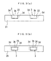
- the present invention is not limited to a specific mode of the opening provided in the circuit board 4, but as a circuit board 21 shown in Fig. 3(a), the opening may be a cutaway portion 22 corresponding to a portion of a mounting face 3b of the point-like light source 3 excluding an electrode portion 3d or a through hole 26 corresponding to the same portion as shown in Fig. 3(b), for example.
- the portion in the radiator plates 5, 15 corresponding to the mounting face 3b of the point-like light source 3 is not deleted as a through hole but continuously constructed of a metal material constituting the bottom face of the recess portions 7, 17, and heat transferred to the filler 6 for heat radiation in direct contact with the mounting face 3b of the point-like light source 3 can be advantageously radiated in a further efficient manner.
- an adhesive filler to be solidified by drying can be used as the filler for heat radiation.
Landscapes
- Engineering & Computer Science (AREA)
- General Engineering & Computer Science (AREA)
- Physics & Mathematics (AREA)
- General Physics & Mathematics (AREA)
- Optics & Photonics (AREA)
- Arrangement Of Elements, Cooling, Sealing, Or The Like Of Lighting Devices (AREA)
- Planar Illumination Modules (AREA)
- Liquid Crystal (AREA)
Abstract
A planar lighting device where workability of charging of a filling agent for heat radiation is improved and where heat produced by a point-like light source is efficiently radiated to achieve high brightness. A planar lighting device (10) has a light guide plate (2); a point-like light source (3) placed on a side end face of the light guide plate (2); and a heat radiation plate (5) having a bottom face (5a) and a side wall (5b). A circuit board (4) on which the point-like light source (3) is mounted is fixed along the side wall (5b). A recess (7) for holding a filling agent (6) for heat radiation is formed in that position of the side wall (5b) which corresponds to the point-like light source (3). As a result, determination of the amount of application of the filling agent (6) for heat radiation and management and storage after the application are facilitated, which improves charging workability.
Description
- The present invention relates to a side-light-type planar lighting device and particularly to a planar lighting device used as illuminating means of a liquid crystal display device.
- As an auxiliary light source for a liquid crystal display device used in a cell phone or the like, a side-light-type planar lighting device in which a primary light source is arranged on a side end face of a light guide plate is widely used (hereinafter, the side end face on which the primary light source is arranged is referred to as an incoming light face). As the primary light source of such a side-light-type planar lighting device, a cold cathode lamp has been used but currently, a point-like light source such as a white LED, which is more excellent in handling performance, is easier to reduce the size thereof and more excellent in impact resistance than a cold cathode lamp (hereinafter simply referred to as an LED) is used in many cases. Fields of application for this type of planar lighting device using a point-like light source are expanding and not limited to small-sized liquid crystal display devices mounted on a cell phone or the like, usage as an auxiliary light source for a liquid crystal display device used for an in-vehicle navigation system with a relatively large display size is now being discussed.
- In order to improve brightness of the side-light-type planar lighting device and to respond to the expansion of the illumination area, it is preferable to increase an electric current to be supplied to each LED or the number of LEDs to be used. However, increase of the electric current to be supplied to the LED or the number of the LEDs is accompanied by increase in a heat amount generated from the LED, and there is a problem that light emission efficiency of the LED is lowered by the temperature rise. Since the heat generated from the LED is transferred to a light guide plate and the light guide plate is expanded concomitantly, displacement is caused in the point-like light source and there is also a problem that bonding efficiency between the point-like light source and the light guide plate is lowered.
- Therefore, various methods have been examined to effectively disperse the heat generated from the LED, and a planar lighting device provided with a radiator plate formed by a metal material such as aluminum having excellent heat conductivity has been proposed. Fig. 4 shows views illustrating a configuration example of such a planar lighting device, in which Fig. 4(a) is a top view and Fig. 4(b) is a side view. A
planar lighting device 100 shown in Fig. 4 comprises alight guide plate 102, anLED 103 mounted on acircuit board 104 and arranged on a side end face of thelight guide plate 102, and aradiator plate 105 made of aplanar portion 105a and aside wall 105b, thelight guide plate 102 being mounted on theplanar portion 105a of theradiator plate 105, and thecircuit board 104 on which theLED 103 is mounted is fixed to theside wall 105b so that heat generated from theLED 103 is efficiently radiated by theradiator plate 105. - Moreover, in the
planar lighting device 100, in order to improve heat conductivity from theLED 103 to theradiator plate 105, afiller 106 for heat radiation made of a silicon compound with high heat conductivity, for example, is interposed between thecircuit board 104 and theside wall 105b of theradiator plate 105. Conventionally, filling of thefiller 106 for heat radiation is carried out by methods in which thefiller 106 for heat radiation is applied with a dispenser or the like to a corresponding spot on the back face side of theLED 103 mounting position or theside wall 105b of theradiator plate 105 in thecircuit board 104 and then, thecircuit board 104 and theradiator plate 105 are fixed to each other using a double-sided adhesive tape or the like, not shown, or in which a through hole (not shown) is provided in advance at a predetermined spot of theradiator plate 105 and after thecircuit board 104 on which theLED 103 is mounted and theradiator plate 105 are fixed together, thefiller 106 for heat radiation is filled through the through hole and the like. - As an example of formation of the through hole in the
radiator plate 105, as shown in a sectional view in Fig. 5, such a planar lighting device is proposed in which athrough hole 116 is formed penetrating through both aradiator plate 115 made of a metal flat plate and acircuit board 114 on which anLED 113 is mounted, and a light source portion is provided by filling anadhesive filler 117 with high heat conductivity into the through hole 116 (SeePatent Document 1, for example).Patent Document 1 describes that the light source portion is manufactured by a series of processes in which thecircuit board 114 is bonded and fixed to theradiator plate 115 with an adhesive 118, the throughhole 116 penetrating through theradiator plate 115 and thecircuit board 114 is drilled and then, theLED 113 is mounted on thecircuit board 114 and then, anadhesive filler 117 is filled into the throughhole 116 and dried and solidified. - Patent Document 1:
Japanese Unexamined Patent Application Publication No. 2002-162626 claim 1,claim 3, Figs. 1 and 2) - However, with the
planar lighting device 100 shown in Fig. 4, in the filling process of thefiller 106 for heat radiation, when thecircuit board 104 onto which thefiller 106 for heat radiation is applied or theradiator plate 105 is temporarily stored by a subsequent process, thefiller 106 for heat radiation can easily transfer and adhere to another place and moreover, particularly when thefiller 106 for heat radiation is applied on theside wall 105b of theradiator plate 105, there is a problem relating to workability in that control of an appropriate application amount is difficult. - On the other hand, with the method of forming the through hole in the
radiator plate 105, since theradiator plate 105 lacks a portion immediately below theLED 103, which is the central portion of heat generation, there is a problem that radiation efficiency is lowered. In this regard, in the light source portion shown in Fig. 5, the portion immediately below theLED 113 is made of theadhesive filler 117 with higher heat conductivity than thecircuit substrate 114 so that the radiation characteristic is improved. However, this does not mean that theradiator plate 115 is present on the back face of theadhesive filler 117, and there is room for improvement in utilization of the radiation characteristic of theradiator plate 115. Moreover, the configuration of the light source portion shown in Fig. 5 is based on the fact that theradiator plate 115 has a simple flat-plane shape, and if this configuration is applied to theradiator plate 105 configured in an L-shape provided with theplanar portion 105a and theside wall 105b as shown in Fig. 4, it becomes extremely difficult to carry out the above-mentioned series of manufacturing processes, which might incur deterioration of workability and increase manufacturing costs. With the planar lighting device inPatent Document 1, no special measures are taken to cope with displacement of the point-like light source caused by heat expansion of the light guide plate. - The present invention was made in view of the above problems and an object thereof is to provide a planar lighting device enabling improved workability of a filling process of filler for heat radiation and can achieve higher brightness by efficiently radiating heat generated from a point-like light source.
- In order to achieve the above object, a planar lighting device according to present invention, provided with a light guide plate and a point-like light source arranged on a side end face of the light guide plate, comprises a radiator plate made of a bottom portion and a side wall, a circuit board on which the point-like light source is mounted is fixed along the side wall, and at a position corresponding to the point-like light source in the side wall, a recess for holding a filler for heat radiation is formed.
- According to the present invention, since the recess portion for holding the filler for heat radiation is formed at a position corresponding to the point-like light source in the side wall of the radiator plate, an appropriate application amount of the filler for heat radiation can be determined easily by discriminating the application amount according to a volume of the recess portion, and since the filler for heat radiation after application is accommodated and held in the recess portion, the radiator plate can be easily managed and stored without transfer or adhesion to another place, which contributes to improvement of workability in the filling process of the filler for heat radiation.
- Moreover, by providing the recess portion to be a reservoir portion for the filler for heat radiation, a filler of a type having considerable fluidity and not requiring drying and solidifying processes can be suitably used, and since such a recess portion can be formed as the lump sum at formation of the radiator plate having the bottom portion and the side wall portion by press machining or the like, the portion can be realized without increasing manufacturing costs as compared with the conventional planar lighting device.
- In a mode of the present invention, the recess portion reaches up to an end of the side wall, and filling of the filler for heat radiation is enabled after fixing the circuit board to the radiator plate, which can further improve the effect of improvement in workability of the filling process. Also, since the filling amount of the filler for heat radiation can be adjusted easily, a peripheral temperature of each point-like light source and its outgoing light amount can be individually adjusted.
- Here, in the present invention, the circuit board preferably has an opening in a region corresponding to at least a part of a mounting face of the point-like light source. By this arrangement, the point-like light source and the radiator plate can be bonded together, while the filler for heat radiation is in direct contact with the mounting face of the point-like light source, and at that time, in the present invention, since a portion corresponding to the point-like light source in the radiator plate is made as a recess portion without forming a through hole in the radiator plate, there is no lacking portion in the radiator plate on the back face side of the point-like light source, and heat transferred from the point-like light source to the filler for heat radiation can be radiated efficiently.
- Moreover, the opening shape of the recess portion is preferably formed slightly larger than the outline of the mounting face of the point-like light source, and the circuit board preferably has flexibility. By this arrangement, even if there is variation in the height from the circuit board of the point-like light source mounted on the circuit board, the variation can be absorbed by flexural deformation of the circuit board into the recess portion of the radiator plate and thus, the outgoing face of the point-like light source can illuminate the light guide plate equally. Similarly, even if the light guide plate is deformed by heat expansion or the like, the deformation is absorbed, displacement of the point-like light source is prevented, and bonding efficiency between the point-like light source and the light guide plate can be stably maintained.
- With the present invention configured as above, in the planar lighting device, workability of filling process of the filler for heat radiation can be improved, and heat generated from the point-like light source can be radiated efficiently so that higher brightness can be achieved.
-
- Figs. 1 are views illustrating a planar lighting device in a first embodiment of the present invention, in which Fig. 1(a) is a plan view and Fig. 1(b) is an A-A sectional view in Fig. 1(a);
- Figs. 2 are views illustrating an essential part of a planar lighting device in a second embodiment of the present invention, in which Fig. 2(a) is a plan view and Fig. 2(b) is an A-A sectional view in Fig. 2(a);
- Fig. 3 is a plan view illustrating a mode of a circuit board having an opening according to the present invention, in which Fig. 3(a) shows a case where the opening is a cutaway portion and Fig. 3(b) shows a case where the opening is a through hole;
- Figs. 4 are views illustrating a configuration example of a conventional planar lighting device, in which Fig. 4(a) is a plan view and Fig. 4(b) is a side view; and
- Fig. 5 is a sectional view illustrating a configuration example of a light source portion in the conventional planar lighting device.
-
- 2: Light guide plate
- 3: Point-like light source
- 3b: Mounting face
- 4: Circuit board
- 5, 15: Radiator plate
- 5a, 15a: Plane portion
- 5b, 15b: Side wall
- 6: Filler for heat radiation
- 7, 17: Recess portion
- An embodiment of the present invention will be described referring to the attached drawings, but each drawing is only for explanation and does not necessarily reflect the actual shape or dimensions of the invention accurately.
- Fig. 1 is a view illustrating an essential part of a planar lighting device 10 in a first embodiment of the present invention, in which Fig. 1(a) is a plan view and Fig. 1(b) is an A-A sectional view. The planar lighting device 10 in this embodiment comprises a
light guide plate 2, a point-like light source 3 mounted on acircuit board 4 and arranged on a side end face of thelight guide plate 2, and aradiator plate 5 made of aplanar portion 5a and aside wall 5b, thelight guide plate 2 being mounted on theplanar portion 5a of theradiator plate 5 and thecircuit board 4 on which theLED 3 is mounted being fixed on theside wall 5b of theradiator plate 5. - Here, in this embodiment, the
light guide plate 2 is a plate-state light guide body preferably formed by injection molding of a transparent resin such as acrylic resin, polycarbonate resin and the like, for example, and the point-like light source 3 is made of a white LED. Thecircuit board 4 is a so-called flexible printed circuit board (FPC) formed with a predetermined wiring pattern for supplying a driving current to the point-like light source on a flexible film base made of polyimide or the like and fixed to theside wall 5b by means such as of attachment or adhesive bonding. - Also, in this embodiment, the
radiator plate 5 is preferably made of a metal material with excellent heat conductivity such as aluminum or the like and has theplanar portion 5a on which thelight guide plate 2 is mounted and theside wall 5b so as to form an L-shape in side view in the direction of the arrow shown in Fig. 1(b). At a position corresponding to the point-like light source 3 of theside wall 5b, arecess portion 7 is provided and by filling afiller 6 for heat radiation into thisrecess portion 7, thecircuit board 4 and theradiator plate 5 are brought into close contact with each other on at least a back face portion of the point-like light source 3, and heat generated from theLED 3 is transferred to theradiator plate 5 with efficiency. At this time, the opening shape of therecess portion 7 is formed somewhat larger than the outline of the mounting face of the point-like light source 3 on thecircuit board 4, and thefiller 6 for heat radiation to be filled in therecess portion 7 is a filler of the type having considerable fluidity and not requiring subjection to drying and solidifying processes such as a silicon compound. - The light source portion of the planar lighting device 10 configured as above can be easily formed by applying an appropriate amount of the
radiator filler 6 with a dispenser or the like into therecess portion 7 of theradiator plate 5 formed in an L-shape by press machining or the like and then, fixing thecircuit board 4 on which the point-like light source 3 is mounted to theside wall 5b with a double-sided adhesive tape or the like, not shown. At this time, in the planar lighting device 10 in this embodiment, the application amount of thefiller 6 for heat radiation can be determined easily and appropriately on the basis of the volume of therecess portion 7, and since thefiller 6 for heat radiation after application is accommodated and held in therecess portion 7, theradiator plate 5 of thecircuit board 4 before fixation can be easily managed and stored without transfer and adhesion of thefiller 6 for heat radiation to other places. - Moreover, as mentioned above, the outline of the opening portion of the
recess portion 7 into which thefiller 6 for heat radiation with fluidity is filled is formed somewhat larger than the outline of the mounting face of the point-likelight source 3 facing thecircuit board 4, and since thecircuit board 4 is an FPC having flexibility, thecircuit board 4 is capable of flexural deformation into therecess portion 7 even after being fixed to theside wall 5b. Thus, even if there is variation in heights of the plurality of point-like light sources 3 mounted on thecircuit board 4 from the circuit board or if thelight guide plate 2 is deformed by heat expansion or the like in an arrow B direction shown in Fig. 1(b), the variation or deformation can be absorbed by flexural deformation of thecircuit board 4 into therecess portion 7 and the point-likelight source 3 can illuminate thelight guide plate 2 stably and equally. - Next, a second embodiment of the present invention will be described referring to Fig. 2, but in the following description, the same components as those in the above-mentioned first embodiment are given the same reference numerals, and duplicated explanation will be omitted as appropriate.
- Fig. 2 shows views illustrating an essential part of a
planar lighting device 20 in the second embodiment of the present invention, in which Fig. 2(a) is a plan view and Fig. 2(b) is an A-A sectional view. Theplanar lighting device 20 in this embodiment has basically the same configuration as the planar lighting device 10 in the first embodiment, but they are different from each other in that therecess portion 17 in aside wall 15b of aradiator plate 15 is formed so as to reach anend portion 15c of theside wall 15b. - In the
planar lighting device 20 configured as above, the light source portion can be easily formed by fixing thecircuit board 4 on which the point-likelight source 3 is mounted to theside wall 15b of theradiator plate 15 formed in an L-shape by press machining or the like with double-sided adhesive tape or the like, not shown, and then, by filling an appropriate amount of thefiller 6 for heat radiation from theend portion 15c side of therecess portion 17, which is an open end, with a dispenser or the like. As above, in theplanar lighting device 20, since the filling process of thefiller 6 for heat radiation can be carried out by filling thefiller 6 for heat radiation into a gap formed in advance between the recess portion of theside wall 15b and thecircuit board 4, the appropriate filling amount can be further determined easily and surely. At the same time, since there is no face where thefiller 6 for heat radiation is significantly exposed to the outside at the end of the filling process, management and storage after the work is further facilitated, and the workability of the filling process of thefiller 6 for heat radiation can be further improved. Moreover, since the filling amount of thefiller 6 for heat radiation can be determined easily and surely, the peripheral temperature of the point-likelight source 3 and hence, its outgoing light amount can be individually adjusted by adjusting the amount for each of the point-like light sources 3. - Here, in the
planar lighting devices 10, 20 shown in Figs. 1 and 2, thecircuit board 4 may have an opening in a region corresponding to at least a part of the mounting face of the point-likelight source 3, with which the mounting face of the point-likelight source 3 and theradiator plates circuit board 4, contributing to the improvement of the radiation efficiency. The present invention is not limited to a specific mode of the opening provided in thecircuit board 4, but as acircuit board 21 shown in Fig. 3(a), the opening may be acutaway portion 22 corresponding to a portion of a mountingface 3b of the point-likelight source 3 excluding anelectrode portion 3d or a throughhole 26 corresponding to the same portion as shown in Fig. 3(b), for example. In the planar lighting device according to the present invention, as mentioned above with reference to Figs. 1 and 2, the portion in theradiator plates face 3b of the point-likelight source 3 is not deleted as a through hole but continuously constructed of a metal material constituting the bottom face of therecess portions filler 6 for heat radiation in direct contact with the mountingface 3b of the point-likelight source 3 can be advantageously radiated in a further efficient manner. - The preferred embodiments according to the present invention have been described but in the present invention, when flexural deformation of the circuit board on which the point-like light source is mounted is not applied, an adhesive filler to be solidified by drying can be used as the filler for heat radiation.
Claims (4)
- A planar lighting device provided with a light guide plate and a point-like light source arranged on a side end face of the light guide plate, characterized in that
a radiator plate made of a bottom portion and a side wall is provided, a circuit board on which the point-like light source is mounted is fixed along the side wall, and a recess portion for holding a filler for heat radiation is formed at a position corresponding to the point-like light source in the side wall. - The planar lighting device according to claim 1, wherein the recess portion reaches an end of the side wall.
- The planar lighting device according to claim 1 or 2, wherein the circuit board has an opening in a region corresponding to at least a part of a mounting face of the point-like light source.
- The planar lighting device according to any one of claims 1 to 3, wherein the opening shape of the recess portion is formed somewhat larger than an outline of the mounting face of the point-like light source and the circuit board has flexibility.
Applications Claiming Priority (2)
| Application Number | Priority Date | Filing Date | Title |
|---|---|---|---|
| JP2005103443A JP4721161B2 (en) | 2005-03-31 | 2005-03-31 | Surface lighting device |
| PCT/JP2005/021253 WO2006112072A1 (en) | 2005-03-31 | 2005-11-18 | Planar lighting device |
Publications (1)
| Publication Number | Publication Date |
|---|---|
| EP1867919A1 true EP1867919A1 (en) | 2007-12-19 |
Family
ID=37114816
Family Applications (1)
| Application Number | Title | Priority Date | Filing Date |
|---|---|---|---|
| EP05806808A Withdrawn EP1867919A1 (en) | 2005-03-31 | 2005-11-18 | Planar lighting device |
Country Status (5)
| Country | Link |
|---|---|
| US (1) | US20090097254A1 (en) |
| EP (1) | EP1867919A1 (en) |
| JP (1) | JP4721161B2 (en) |
| TW (1) | TW200702594A (en) |
| WO (1) | WO2006112072A1 (en) |
Cited By (1)
| Publication number | Priority date | Publication date | Assignee | Title |
|---|---|---|---|---|
| CN104010108A (en) * | 2008-10-30 | 2014-08-27 | 夏普株式会社 | Illuminating device, image reading apparatus and image forming apparatus |
Families Citing this family (12)
| Publication number | Priority date | Publication date | Assignee | Title |
|---|---|---|---|---|
| JP4919761B2 (en) | 2006-10-27 | 2012-04-18 | 日東電工株式会社 | Wiring circuit board and electronic component device |
| EP3578881B1 (en) * | 2007-05-02 | 2022-10-26 | Signify Holding B.V. | Solid-state lighting device |
| JP5057081B2 (en) * | 2008-03-24 | 2012-10-24 | 東芝ライテック株式会社 | Lighting device |
| DE102009027493B4 (en) * | 2009-07-07 | 2020-04-23 | Robert Bosch Gmbh | Cooling of an LED-illuminated display module |
| WO2012053413A1 (en) * | 2010-10-20 | 2012-04-26 | シャープ株式会社 | Lighting device and liquid-crystal display device |
| WO2012102200A1 (en) * | 2011-01-27 | 2012-08-02 | シャープ株式会社 | Lighting device, display device, and television reception device |
| JP2012212526A (en) * | 2011-03-30 | 2012-11-01 | Sony Corp | Display device |
| JP5696846B2 (en) | 2011-04-18 | 2015-04-08 | ミネベア株式会社 | Surface lighting device |
| TWI537646B (en) * | 2011-05-11 | 2016-06-11 | 州巧科技股份有限公司 | Light source device applied to liquid crystal display and backlight module and manufacturing method thereof |
| KR101276858B1 (en) * | 2011-07-01 | 2013-06-18 | 엘지전자 주식회사 | Circuit board, backlight unit, and liquid crystal display using the same |
| CN102620214A (en) * | 2012-04-11 | 2012-08-01 | 深圳市华星光电技术有限公司 | Backlight module and liquid crystal display device |
| JP7443930B2 (en) * | 2020-05-26 | 2024-03-06 | 日本精機株式会社 | Vehicle display device and method for manufacturing vehicle display device |
Family Cites Families (7)
| Publication number | Priority date | Publication date | Assignee | Title |
|---|---|---|---|---|
| ATE47624T1 (en) * | 1984-11-15 | 1989-11-15 | Japan Traffic Manage Tech Ass | SIGNAL LIGHT UNIT WITH HEAT DISSIPATION. |
| JPH0584978U (en) * | 1991-05-02 | 1993-11-16 | スタンレー電気株式会社 | LED display |
| US6068381A (en) * | 1998-01-29 | 2000-05-30 | Nu-Tech & Engineering, Inc. | Back lighting device with central opening frame member and a unitized lamp and rigid radially extended terminals assembly |
| JP2002245829A (en) * | 2000-12-14 | 2002-08-30 | Fujitsu Ltd | Backlight, display device and method of manufacturing |
| JP4815675B2 (en) * | 2001-02-02 | 2011-11-16 | ソニー株式会社 | Liquid crystal display device and backlight device for liquid crystal display element |
| JP3882163B2 (en) * | 2001-10-24 | 2007-02-14 | ミネベア株式会社 | Surface lighting device |
| JP2003281924A (en) * | 2002-03-22 | 2003-10-03 | Sony Corp | Light source device, method of manufacturing light source device, surface illumination device, and liquid crystal display device |
-
2005
- 2005-03-31 JP JP2005103443A patent/JP4721161B2/en not_active Expired - Lifetime
- 2005-11-18 WO PCT/JP2005/021253 patent/WO2006112072A1/en not_active Ceased
- 2005-11-18 US US11/887,443 patent/US20090097254A1/en not_active Abandoned
- 2005-11-18 EP EP05806808A patent/EP1867919A1/en not_active Withdrawn
-
2006
- 2006-03-08 TW TW095107770A patent/TW200702594A/en unknown
Non-Patent Citations (1)
| Title |
|---|
| See references of WO2006112072A1 * |
Cited By (2)
| Publication number | Priority date | Publication date | Assignee | Title |
|---|---|---|---|---|
| CN104010108A (en) * | 2008-10-30 | 2014-08-27 | 夏普株式会社 | Illuminating device, image reading apparatus and image forming apparatus |
| CN104010108B (en) * | 2008-10-30 | 2017-04-12 | 夏普株式会社 | Illuminating device, image reading apparatus and image forming apparatus |
Also Published As
| Publication number | Publication date |
|---|---|
| JP2006286347A (en) | 2006-10-19 |
| TW200702594A (en) | 2007-01-16 |
| JP4721161B2 (en) | 2011-07-13 |
| WO2006112072A1 (en) | 2006-10-26 |
| US20090097254A1 (en) | 2009-04-16 |
Similar Documents
| Publication | Publication Date | Title |
|---|---|---|
| US20090201699A1 (en) | Planar Illumination Device and Manufacturing Method of Same | |
| KR101282125B1 (en) | Back-light assembly and display device having the same | |
| EP1947490B1 (en) | Backlight assembly and cover for a compact display apparatus | |
| US7458709B2 (en) | Method for mounting a surface lighting system and surface lighting system | |
| JP4226796B2 (en) | Liquid crystal display | |
| US20090097254A1 (en) | Planar Lighting Device | |
| KR101418374B1 (en) | Printed circuit board, and back light unit and liquid crystal display having the same | |
| US8702262B2 (en) | Light source module and display apparatus having the same | |
| US10247378B2 (en) | Metal PCB, headlight module having metal PCB applied thereto, and method for assembling headlight module | |
| KR101301317B1 (en) | Backlight unit and liquid crystal display using the same | |
| US20070189011A1 (en) | Light-generating module, backlight assembly and display device having the same, and method thereof | |
| US8297826B2 (en) | Backlight unit and display device including the same | |
| US20060098441A1 (en) | Backlight module | |
| KR20070076879A (en) | LCD Display Module | |
| CN102667598B (en) | Heat radiating printed circuit board and chassis assembly having the same | |
| CN102193245B (en) | Liquid crystal display device | |
| US20070247564A1 (en) | Blacklight unit having a heat receiving member | |
| KR20130040661A (en) | Back light unit and display device having the same | |
| CN102102863B (en) | Luminous source radiating structure and backlight module | |
| JP4618546B2 (en) | Liquid crystal display device | |
| KR101342652B1 (en) | liquid crystal display | |
| TWI280093B (en) | Structure for fixing printed circuit board and method of fixing thereof | |
| CN218729646U (en) | Backlight module and display device | |
| TWI298410B (en) | Backlight module | |
| CN103196082A (en) | Backlight module and liquid crystal display |
Legal Events
| Date | Code | Title | Description |
|---|---|---|---|
| PUAI | Public reference made under article 153(3) epc to a published international application that has entered the european phase |
Free format text: ORIGINAL CODE: 0009012 |
|
| 17P | Request for examination filed |
Effective date: 20071022 |
|
| AK | Designated contracting states |
Kind code of ref document: A1 Designated state(s): DE FR GB |
|
| DAX | Request for extension of the european patent (deleted) | ||
| RBV | Designated contracting states (corrected) |
Designated state(s): DE FR GB |
|
| STAA | Information on the status of an ep patent application or granted ep patent |
Free format text: STATUS: THE APPLICATION HAS BEEN WITHDRAWN |
|
| 18W | Application withdrawn |
Effective date: 20091104 |