EP1867489A1 - Process for printing and coating, and apparatus implementing the process - Google Patents
Process for printing and coating, and apparatus implementing the process Download PDFInfo
- Publication number
- EP1867489A1 EP1867489A1 EP06012386A EP06012386A EP1867489A1 EP 1867489 A1 EP1867489 A1 EP 1867489A1 EP 06012386 A EP06012386 A EP 06012386A EP 06012386 A EP06012386 A EP 06012386A EP 1867489 A1 EP1867489 A1 EP 1867489A1
- Authority
- EP
- European Patent Office
- Prior art keywords
- medium
- coating
- printing
- drying
- inline
- Prior art date
- Legal status (The legal status is an assumption and is not a legal conclusion. Google has not performed a legal analysis and makes no representation as to the accuracy of the status listed.)
- Granted
Links
- 238000000576 coating method Methods 0.000 title claims abstract description 138
- 238000007639 printing Methods 0.000 title claims abstract description 96
- 238000000034 method Methods 0.000 title claims abstract description 49
- 230000008569 process Effects 0.000 title claims abstract description 42
- 239000011248 coating agent Substances 0.000 title claims description 134
- 238000001035 drying Methods 0.000 claims abstract description 87
- 230000011664 signaling Effects 0.000 claims description 14
- 239000007921 spray Substances 0.000 claims description 14
- 238000009423 ventilation Methods 0.000 claims description 5
- 230000001360 synchronised effect Effects 0.000 claims description 4
- 239000000463 material Substances 0.000 description 25
- 239000000976 ink Substances 0.000 description 18
- 238000010030 laminating Methods 0.000 description 13
- 230000007246 mechanism Effects 0.000 description 7
- 239000000758 substrate Substances 0.000 description 6
- 238000010438 heat treatment Methods 0.000 description 4
- 230000006866 deterioration Effects 0.000 description 3
- 239000010410 layer Substances 0.000 description 3
- 239000002245 particle Substances 0.000 description 3
- 230000002441 reversible effect Effects 0.000 description 3
- 239000002966 varnish Substances 0.000 description 3
- 239000011247 coating layer Substances 0.000 description 2
- 230000003111 delayed effect Effects 0.000 description 2
- 238000005265 energy consumption Methods 0.000 description 2
- 230000003993 interaction Effects 0.000 description 2
- 230000004048 modification Effects 0.000 description 2
- 238000012986 modification Methods 0.000 description 2
- 230000005855 radiation Effects 0.000 description 2
- 101100508818 Mus musculus Inpp5k gene Proteins 0.000 description 1
- 101100366438 Rattus norvegicus Sphkap gene Proteins 0.000 description 1
- 239000000470 constituent Substances 0.000 description 1
- 238000001723 curing Methods 0.000 description 1
- 230000002542 deteriorative effect Effects 0.000 description 1
- 238000007599 discharging Methods 0.000 description 1
- 238000005562 fading Methods 0.000 description 1
- 238000007602 hot air drying Methods 0.000 description 1
- 238000007641 inkjet printing Methods 0.000 description 1
- 230000010354 integration Effects 0.000 description 1
- 239000005001 laminate film Substances 0.000 description 1
- 239000002648 laminated material Substances 0.000 description 1
- 238000009877 rendering Methods 0.000 description 1
- 239000007787 solid Substances 0.000 description 1
- 239000002904 solvent Substances 0.000 description 1
- 238000005507 spraying Methods 0.000 description 1
Images

Classifications
-
- B—PERFORMING OPERATIONS; TRANSPORTING
- B41—PRINTING; LINING MACHINES; TYPEWRITERS; STAMPS
- B41J—TYPEWRITERS; SELECTIVE PRINTING MECHANISMS, i.e. MECHANISMS PRINTING OTHERWISE THAN FROM A FORME; CORRECTION OF TYPOGRAPHICAL ERRORS
- B41J11/00—Devices or arrangements of selective printing mechanisms, e.g. ink-jet printers or thermal printers, for supporting or handling copy material in sheet or web form
- B41J11/0015—Devices or arrangements of selective printing mechanisms, e.g. ink-jet printers or thermal printers, for supporting or handling copy material in sheet or web form for treating before, during or after printing or for uniform coating or laminating the copy material before or after printing
- B41J11/002—Curing or drying the ink on the copy materials, e.g. by heating or irradiating
- B41J11/0021—Curing or drying the ink on the copy materials, e.g. by heating or irradiating using irradiation
- B41J11/00214—Curing or drying the ink on the copy materials, e.g. by heating or irradiating using irradiation using UV radiation
-
- B—PERFORMING OPERATIONS; TRANSPORTING
- B41—PRINTING; LINING MACHINES; TYPEWRITERS; STAMPS
- B41J—TYPEWRITERS; SELECTIVE PRINTING MECHANISMS, i.e. MECHANISMS PRINTING OTHERWISE THAN FROM A FORME; CORRECTION OF TYPOGRAPHICAL ERRORS
- B41J11/00—Devices or arrangements of selective printing mechanisms, e.g. ink-jet printers or thermal printers, for supporting or handling copy material in sheet or web form
- B41J11/0015—Devices or arrangements of selective printing mechanisms, e.g. ink-jet printers or thermal printers, for supporting or handling copy material in sheet or web form for treating before, during or after printing or for uniform coating or laminating the copy material before or after printing
- B41J11/002—Curing or drying the ink on the copy materials, e.g. by heating or irradiating
- B41J11/0022—Curing or drying the ink on the copy materials, e.g. by heating or irradiating using convection means, e.g. by using a fan for blowing or sucking air
-
- B—PERFORMING OPERATIONS; TRANSPORTING
- B41—PRINTING; LINING MACHINES; TYPEWRITERS; STAMPS
- B41J—TYPEWRITERS; SELECTIVE PRINTING MECHANISMS, i.e. MECHANISMS PRINTING OTHERWISE THAN FROM A FORME; CORRECTION OF TYPOGRAPHICAL ERRORS
- B41J11/00—Devices or arrangements of selective printing mechanisms, e.g. ink-jet printers or thermal printers, for supporting or handling copy material in sheet or web form
- B41J11/0015—Devices or arrangements of selective printing mechanisms, e.g. ink-jet printers or thermal printers, for supporting or handling copy material in sheet or web form for treating before, during or after printing or for uniform coating or laminating the copy material before or after printing
- B41J11/002—Curing or drying the ink on the copy materials, e.g. by heating or irradiating
- B41J11/0024—Curing or drying the ink on the copy materials, e.g. by heating or irradiating using conduction means, e.g. by using a heated platen
Definitions
- Printing/laminating processes have as drawback that the laminating process is inevitably applied to the entire recording medium for the width of the laminating member. Furthermore, the laminating member and the printed medium need to be aligned, and laminating requires the presence of a laminate member feeding roller, often a heater and related mechanics, rendering the image forming apparatus rather bulky and complex.
- the drying process in US 2002/0118987 A1 copes with a problem that is specific to laminating, i.e. the presence of air pockets or bubbles in between the laminate and medium.
- the drying process executed in between the recording and laminating in US 2002/0118987 A1 is not synchronized with the recording process. Further, the drying is applied to the entire recording medium, which is not efficient in terms of energy consumption.
- the above defined object is realized by a process for printing and coating of a medium as defined by claim 1, comprising the steps of:
- the active post-drying may be realised through heated surfacing, ventilation, radiation, UV (ultraviolet) treatment, etc. or through combination of such techniques.
- a further optional feature of the present invention, defined by claim 3, is that the drying in step b and/or the drying in step d are executed only on portions of the medium that are coated in said step c.
- the active ventilation may be implemented through one or more relatively small ventilator(s) fixedly mounted onto or attached to the coating device,
- the surface heating can be realised through heating the surface over which the medium is moved towards the coating device via a conductive resistor underneath the surface.
- step c is synchronized with the printing in step a through signalling received from the printing process in step a.
- This optional element is defined by claim 5.
- one way to synchronize the coating with the printing is through signalling received from the printing device.
- the signalling may be indicative for the start and stop of the movement of the print head printing successive lines of an image.
- the coating device may be deployed in conjunction with a sensor that senses advancement of the medium and prevents the coating device from applying coating material while the medium is being advanced.
- a sensor in the printing device that senses the start and stop of the print head.
- pre-configuration of the coating step preventing the coating material to be applied when the medium is progressed through the printing apparatus.
- the drying and coating can both be restricted to portions of the medium that are printed, This way the power consumption for the drying and coating steps is minimized.
- the apparatus according to the current invention may comprise a coating cartridge, connected to the inline coating device.
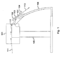
- the printing and coating apparatus drawn in Fig. 1 contains a printing portion or printing device 101 on a vertical support 105, and a coating portion on a second support 106.
- Support 105 and support 106 may be integrated into a single stand or may be connected as depicted in Fig. 1.
- the coating portion comprises a first drying device 102, a coating device 103 and a second drying device 104, as well as a heated surface 107 for conveying the medium.
- the heated surface is depicted as convex, but it may be flat or concave, depending on the integration with the printing equipment.
- the drive mechanism advancing the medium may be integrated in the second part of the apparatus, i,e. the part where also the drying and coating devices reside.
- a sensor may have to be foreseen which backwards signals advancement of the medium towards the printing apparatus in order to ensure that the printing of the image is interrupted each time the medium is moved forward.
- both the printing part and the coating part of the apparatus may be equipped with a drive mechanism to independently advance the medium.
- a buffer in between the printing part and coating part can prevent rupturing the medium, or the two drive mechanisms may be controlled or operationally coupled in order to avoid rupturing the medium.
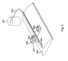
- Fig. 2 and Fig. 3 show a container wherein the coating material is kept under pressure
- the coating material could alternatively be kept under pressure in a replaceable cartridge that is for instance mounted on the coating spray head.
- a replaceable cartridge that is for instance mounted on the coating spray head.
- Such cartridge would have an interface with nozzles enabling the coating material to reach the spray head.
- the nozzles and material of the printing cartridge containing the coating material would be designed depending on the constitution of the coating material.
Landscapes
- Health & Medical Sciences (AREA)
- General Health & Medical Sciences (AREA)
- Toxicology (AREA)
- Ink Jet (AREA)
- Photographic Developing Apparatuses (AREA)
- Application Of Or Painting With Fluid Materials (AREA)
Abstract
Description
- The present invention generally relates to printing on a medium or substrate, e.g. through ejection of ink droplets in an ink jet process, and coating of the printed medium or substrate. The coating generally improves the image quality, weather or moisture resistance of the image, resistance to fading, and it avoids deterioration of the image for instance through UV light, scratches, etc.
- To produce high quality images that resist certain conditions such as moisture, heat, etc. either printing/laminating or printing/coating processes are described in literature and commercial products are available implementing such processes.
- Printing/laminating processes have as drawback that the laminating process is inevitably applied to the entire recording medium for the width of the laminating member. Furthermore, the laminating member and the printed medium need to be aligned, and laminating requires the presence of a laminate member feeding roller, often a heater and related mechanics, rendering the image forming apparatus rather bulky and complex.
-
US Patent Application No. 2002/0118987 A1 for instance describes an image forming apparatus (100 in Fig. 1) having a recording portion (20 in Fig. 1) and a laminating portion (70 in Fig. 1). The recording portion discharges ink from one or plural ink jet recording heads (1 in Fig. 1) for recording an image on a recording medium. The laminating portion applies a laminate material onto the recording medium. After the image recording, the leading edge of the paper or recording medium is detected by a sensor (79 in Fig. 4), and the recording medium is passed through a pair of heated rollers (71A, 71 B in Fig. 1) in the laminating portion in order to dry the recording medium and prevent that moisture gets trapped between the recording medium and the laminate layer. After the drying step, a pair of heated pressurizing rollers (72A, 72B) applies a laminate film on the recording medium. - The drying process in
US 2002/0118987 A1 copes with a problem that is specific to laminating, i.e. the presence of air pockets or bubbles in between the laminate and medium. In addition to suffering from the typical shortcomings inherent to laminating, the drying process executed in between the recording and laminating inUS 2002/0118987 A1 is not synchronized with the recording process. Further, the drying is applied to the entire recording medium, which is not efficient in terms of energy consumption. - Some of the drawbacks inherently associated with printing/laminating processes, are overcome by printing/coating processes wherein the printed or recorded medium is protected through a varnish or variant coating material that is sprayed onto portions of the medium that have been printed.
- Such an integrated printing/coating process is described for example in
Japanese Patent Application JP61047284 - The just mentioned shortcoming related to the process described in
Japanese Patent Application JP61047284 German Patent Application DE 100 51 088 A1 . In the single-stage process disclosed therein, a surface is printed and the printed surface is covered by a sprayed varnish. Optionally, a primer is sprayed onto the surface before the image is printed. To avoid impact between the printing and varnishing (or coating) the printing process uses oil, ultra violet or solvent inks, and a time interval of preferably 4 minutes, but realistically up to 10 minutes is respected between the printing step and coating step. The process disclosed inDE 100 51 088 A1 however is slow and plagued by undue restrictions such as the choice of certain inks. In particular when the surface is sprayed with a primer before the image is printed, it can take up to 20 minutes to print and coat a single image according to the process ofDE 100 51 088 A1 . - A variant prior art solution for creating photographic quality prints is described in
US Patent Application 2003/0013033 . According to the method disclosed therein, an image is reverse printed on a transparent substrate through ink jet, electrostatic or other printing methods. Thereafter, a particle-based undercoat layer is coated onto the printed substrate during an in-line process rather than a separate offline step. The particle-based undercoat serves as a solid-filled, reflective background for the image. In certain embodiments, the transparent carrier is pre-heated to facilitate adhesion of the undercoat layer to the transparent medium. - The reverse technique disclosed in
US 2003/0013033 requires good adhesion between the ink and the transparent substrate, and usually relies on a process called fusing to affix the particle-based undercoat to the transparent carrier. The pre-heating must be applied to the entire surface and is typically realized by a conductive heater under the transparent carrier or a radiant heater above the carrier surface. The heating is not synchronized or aligned with the printing process. - It is an object of the present invention to provide a process for printing and coating that overcomes the various drawbacks of the prior art solutions described above. In particular, it is an object to enable inline printing/coating in a timely fashion without the risk of deteriorating the image through impact between the printing ink and coating material, and without a need for additional processes like fusing. Further, it is an object to efficiently consume and where possible reduce energy consumption.
- According to the invention, the above defined object is realized by a process for printing and coating of a medium as defined by claim 1, comprising the steps of:
- a. printing an image on the medium, thereby generating a printed medium;
- b. inline drying the printed medium in synchronism with the printing in step a, thereby generating a dried printed medium; and
- c. inline coating the dried printed medium in synchronism with the printing in step a, thereby generating a coated printed medium.
- Indeed, through active inline drying in synchronism with the printing, the amount of time required in between printing and coating to avoid interaction between the ink and coating material is reduced significantly. Further, through inline coating in synchronism with the printing step, the movements of the coating device are in sync with the movements of the printing device, and the coating device is controlled in such a way that no coating material is sprayed onto the medium while the medium is progressed. Thanks to this synchronism, the coating device needs no medium drive mechanism of its own, and the entire process of printing and coating is automated in a single cycle. Consequently, the current invention adds to reduce the process and hardware complexity.
- In addition to the process defined by claim 1, the current invention relates to a corresponding apparatus for printing and coating as defined by claim 7, comprising:
- a. a printing device for printing an image on a medium to thereby generate a printed medium;
- b. an inline drying device for drying at least portions of the printed medium to thereby generate a dried printed medium, the inline drying device being adapted to operate in synchronism with the printing device; and
- c. an inline coating device for coating at least portions of the dried printed medium to thereby generate a coated printed medium, the inline coating device being adapted to operate in synchronism with the printing device.
- An optional feature of respectively the process and apparatus according to the current invention, defined by claims 2 and 8, is that the current invention further may comprise inline drying the coated printed medium in synchronism with the printing in step a.
- This way, the risk for deterioration of the coated printed medium is further reduced by accelerating the drying process for the coating material through active post-drying.
- The active post-drying may be realised through heated surfacing, ventilation, radiation, UV (ultraviolet) treatment, etc. or through combination of such techniques.
- A further optional feature of the present invention, defined by claim 3, is that the drying in step b and/or the drying in step d are executed only on portions of the medium that are coated in said step c.
- By restriction of the active drying before and eventually after the coating step to portions of the medium that have been printed, the power consumption and consequently the operational cost of printing and coating get reduced. The drying can be reduced to coated portions only for instance by rigidly mounting the drying device(s) and the coating device on a single carriage, movable mounted along a bridge. This way, the drying device(s) move only in zones where the coating material is sprayed.
- Another optional feature of the present invention is that the drying in step b and/or the drying in step d involve ventilation and/or heated surfacing. This optional feature is defined by claim 4.
- Indeed, although various alternate techniques can be considered for the drying before and eventually after the coating, a combination of active ventilation and heated surfacing is preferred. The active ventilation may be implemented through one or more relatively small ventilator(s) fixedly mounted onto or attached to the coating device, The surface heating can be realised through heating the surface over which the medium is moved towards the coating device via a conductive resistor underneath the surface.
- Yet another optional characteristic of the present invention, is that the inline coating in step c is synchronized with the printing in step a through signalling received from the printing process in step a. This optional element is defined by claim 5.
- Thus, one way to synchronize the coating with the printing is through signalling received from the printing device. The signalling may be indicative for the start and stop of the movement of the print head printing successive lines of an image. As an alternative to the signalling, the coating device may be deployed in conjunction with a sensor that senses advancement of the medium and prevents the coating device from applying coating material while the medium is being advanced. Another alternative is a sensor in the printing device that senses the start and stop of the print head. Yet another option is pre-configuration of the coating step preventing the coating material to be applied when the medium is progressed through the printing apparatus.
- Still an option of the printing process according to the present invention is that the inline coating in step c is executed on portions of the medium identified by signalling received from the printing process in step a. This optional feature is defined by claim 6.
- Indeed, in addition to signalling the start and stop of the movement of the print head, electronic signalling between the printing device and coating device may be indicative for the portions of the medium that are printed, e.g. the width of the print job, full scan signalling, skip signalling for white space, etc, This way, the power consumption is further reduced be restricting the coating exactly to the printed portions that require protection. The signalling may further be indicative for the speed of the print head, the print step, and other parameters of the printing device.
- Optionally, as defined by claim 9, the printing and coating apparatus according to the present invention may comprise a carriage, movably mounted on a bridge, for carrying the inline drying device, the inline coating device and the second inline drying device.
- Thus, as already explained above, by rigidly mounting the drying device(s) and coating device on a single carriage, the drying and coating can both be restricted to portions of the medium that are printed, This way the power consumption for the drying and coating steps is minimized.
- As is indicated by claim 10, the apparatus according to the current invention may comprise a coating cartridge, connected to the inline coating device.
- Indeed, as an alternative to an external container connected to the coating device via a coating material supply pipe, the coating material may be kept in a coating cartridge that fits in a particular portion of the apparatus according to the present invention and that is easily replaceable by the end-user of the apparatus.
- Again optionally, as defined by claim 11, the inline coating device in the apparatus according to the present invention may comprise a Rayleigh breakup spray head.
- As opposed to a regular spray head, such Rayleigh breakup spray head avoids uncontrolled spraying of drops of the coating material.
- The current invention further relates to a process for coating and printing a medium as defined by claim 12, comprising the steps of:
- a. drying the medium to thereby generate a dried medium;
- b. inline coating the dried medium to thereby generate a coated medium;
- c. inline drying the coated medium to thereby generate a dried coated medium; and
- d. printing an image on the dried coated medium to thereby generate a printed coated medium, whereby the drying in step a, the inline coating in step b and the inline drying in step c are executed in synchronism with the printing in step d.
- The present invention in addition also relates to a corresponding apparatus as defined by claim 13, comprising:
- a. a drying device for drying a medium to thereby generate a dried medium;
- b. a coating device for inline coating the dried medium to thereby generate a coated medium;
- c. a second drying device for inline drying the coated medium to thereby generate a dried coated medium; and
- d. a printing device for printing an image on the dried coated medium to thereby generate a printed coated medium, whereby the drying device, the coating device and the second drying device are adapted to operate in synchronism with the printing device.
-
- Fig. 1 illustrates an embodiment of the apparatus for printing and coating according to the present invention;
- Fig. 2 is a top view of the coating and drying portion that forms part of the embodiment of the current invention drawn in Fig. 1; and
- Fig. 3 is a side view of the coating and drying portion that forms part of the embodiment of the current invention drawn in Fig. 1.
- The printing and coating apparatus drawn in Fig. 1 contains a printing portion or
printing device 101 on avertical support 105, and a coating portion on asecond support 106.Support 105 andsupport 106 may be integrated into a single stand or may be connected as depicted in Fig. 1. The coating portion comprises afirst drying device 102, acoating device 103 and asecond drying device 104, as well as aheated surface 107 for conveying the medium. - The
printing device 101 in Fig. 1 is supposed to be an ink jet printing device able to digitally print an image on a substrate ormedium 111 by discharging ink from an ink jet recording head onto the medium 111. The medium 111 to be printed can be paper, photo paper, a poster, a transparency, a t-shirt, etc. The image can be a picture, a graph, a text, a photo, an artwork, etc. or a combination thereof, Theprinting device 101 contains a sensor, not drawn in Fig. 1, to detect the leading edge of the medium 111 and a drive mechanism to advance the medium 111 through the printing and coating apparatus, such as for instance one or more rollers driven by a step motor. The printed medium is referenced by 112 in Fig. 1 and fed automatically into the coating portion of the apparatus that will be described in detail in the following paragraphs referring to Fig. 2 and Fig. 3. The apparatus in Fig. 1 at last outputs a coated printedmedium 113. - Fig. 2 shows the
first drying device 102,coating device 103 andsecond drying device 104 in more detail. The first drying device is constituted by a relativelysmall ventilator 202. The coating device consists of a Rayleigh breakup spray head or a piezo actuated print head or a print head with electro-mechanical actuation 203 connected via a coatingmaterial supply conduct 223 to a coating material reservoir that is kept under pressure. Thesecond drying device 204 is also constituted by a relativelysmall ventilator 204, similar to the first one. Thefirst ventilator 202, thecoating spray head 203 and thesecond ventilator 204 are rigidly mounted on asingle carriage 221 that is laterally moveable along abridge 224. This way, thecoating spray head 203 and theventilators medium 112 is progressively advanced in order to get dried and coated. - Fig. 3 at last shows a side view of the drying and coating portion of the printing apparatus of Fig. 1, the arrows indicating the path followed by the printed
medium 312 along theheated surface 300. The first drying device or ventilator is referenced by 302 in Fig. 3, the coating spray head is referenced by 303, and the second drying device or ventilator is referenced by 304 in Fig. 3. These three devices are mounted oncarriage 321 which can slide along thebridge 324. Fig. 3 further shows thecoating material container 322 and the coatingmaterial supply pipe 323 that connects an outlet of thecontainer 322 to an inlet of thecoating spray head 303. Theheated surface 300 corresponds to reference 107 in Fig. 1 and 200 in Fig. 2. The coated printed medium 313 (corresponding to 113 in Fig. 1) leaves the apparatus via a slot in between theheated surface 300 and thesecond ventilator 304, eventually to be collected in a tray not shown in any of the figures. The heated surface is depicted as convex, but it may be flat or concave, depending on the integration with the printing equipment. - The process executed by the printing and coating apparatus illustrated by Fig. 1, Fig. 2 and Fig. 3 will now be described. Upon instruction of software or instruction of the end-user, an image will be printed on a medium 111 and the medium shall be coated. Thereto, the medium 111 is sensed and guided into the
printing device 101 where an ink jet print head prints the image on the medium. The printedmedium 112 or the portion of the medium that has been printed is advanced into the second part of the apparatus where theventilator 102,coating device 103 andsecond ventilator 104 reside. In this second part, the ink on the printedmedium 112 is partially dried by sliding the medium 112 alongheated surface 107, partially dried by air-ventilating the space in between the sliding printedmedium 112 andventilator 102. The portions of the printedmedium 112 whereon the image has been printed are coated with a varnish spray evenly distributed by the coating spray head that forms part ofcoating device 103. A sensor, not drawn in the figures, senses when the print head in 101 starts moving to print a line of the image. The sensor flags this moment to thecoating device 103, which thereupon starts coating a line or lateral section on the printedmedium 112. Thecoating device 103 is preconfigured to know the speed of the print head and the width of the print job and is controlled to stop applying the coating material before the print head reaches the end of the line. This way, it is avoided that coating material is sprayed over portions of the printedmedium 112 while the medium is moved forward by the drive mechanism inprinting device 101. Theventilator 102 moves laterally together with thecoating device 103 and consequently dries the ink only in a zone that will be coated soon, during the next passage of thecoating device 103. Post-drying, i.e. drying of the coating material on the coated printedmedium 113 is done byventilator 104 which also moves laterally together with thecoating device 103 and which consequently only dries areas on the printedmedium 113 that have been coated recently, i.e. in a previous passage of thecoating device 103. The coated printed medium 113 leaves the apparatus through an exit slot in between theheated surface 107 and thesecond ventilator 104. - In a variant embodiment of the apparatus according to the present invention, the drive mechanism advancing the medium may be integrated in the second part of the apparatus, i,e. the part where also the drying and coating devices reside. In such embodiment, a sensor may have to be foreseen which backwards signals advancement of the medium towards the printing apparatus in order to ensure that the printing of the image is interrupted each time the medium is moved forward. In another variant embodiment of the current invention, both the printing part and the coating part of the apparatus may be equipped with a drive mechanism to independently advance the medium. In such embodiment, a buffer in between the printing part and coating part can prevent rupturing the medium, or the two drive mechanisms may be controlled or operationally coupled in order to avoid rupturing the medium.
- As an alternative to the sensor described above in relation to the embodiment of the current invention where movement of the print head is sensed and flagged to the coating device, or to the sensor reverse signalling advancement of the medium in the embodiment of the previous paragraph, the printing device and coating device may be interfacing electronically to signal movement of the print head. In case such interface is foreseen, the signalling interchanged may be enhanced to be indicative for printer, medium or image related parameters such as the width of the print job or maximum width of the coating job, the medium quality and size (e.g. paper thickness and size), the print head speed, the step of the printing device. In another alternative embodiment of the invention, such parameters may be manually configurable by the user of the apparatus through a touch screen, keypad, or other user interface integrated with the apparatus, or the parameters may be software configurable via a PC (Personal Computer) connection.
- Although Fig. 2 and Fig. 3 show a container wherein the coating material is kept under pressure, the coating material could alternatively be kept under pressure in a replaceable cartridge that is for instance mounted on the coating spray head. Such cartridge would have an interface with nozzles enabling the coating material to reach the spray head. The nozzles and material of the printing cartridge containing the coating material would be designed depending on the constitution of the coating material.
- Instead of the ventilators deployed in the above described embodiment, the drying and post-drying can be achieved through variant drying techniques, such as UV (ultra-violet) drying, hot air drying, radiation, heated surface drying, etc., and/or combinations of these techniques. Post-drying may be enhanced through accurate selection of the coating material constituents and/or through curing techniques.
- Variant embodiments of the apparatus according to the present invention may not include the second ventilator or alternate post-drying mechanisms, i.e. natural post-drying may be relied upon. In still other embodiments of the invention, the drying in between printing and coating and the post-drying may be separately configurable, and the drying means need not necessarily be mounted on one and the same carriage.
- Further, the apparatus according to the present invention may be employed with the coating device ahead of the printing device, such that the medium can receive a primer before being printed. The medium can be dried before the primer is sprayed onto portions of the medium where an image will be printed. The portions of the medium that have received the primer are thereafter dried before the image is printed. In a more advanced embodiment which is able to treat the medium with a primer and to protect the printed images with a coating layer, the printed medium may be dried after the image has been printed, coated and post-dried similarly as in the embodiment described above with reference to the drawings, such that the image printed on the primer-treated medium is further protected through a top coating layer.
- Although the present invention has been illustrated by reference to specific embodiments, it will be apparent to those skilled in the art that the invention is not limited to the details of the foregoing illustrative embodiments, and that the present invention may be embodied with various changes and modifications without departing from the spirit and scope thereof. The present embodiments are therefore to be considered in all respects as illustrative and not restrictive, the scope of the invention being indicated by the appended claims rather than by the foregoing description, and all changes which come within the meaning and range of equivalency of the claims are therefore intended to be embraced therein. In other words, it is contemplated to cover any and all modifications, variations or equivalents that fall within the spirit and scope of the basic underlying principles and whose essential attributes are claimed in this patent application. It will furthermore be understood by the reader of this patent application that the words "comprising" or "comprise" do not exclude other elements or steps, that the words "a" or "an" do not exclude a plurality, and that a single element, such as a computer system, a processor, or another integrated unit may fulfil the functions of several means recited in the claims. Any reference signs in the claims shall not be construed as limiting the respective claims concerned. The terms "first", "second", third", "a", "b", "c", and the like, when used in the description or in the claims are introduced to distinguish between similar elements or steps and are not necessarily describing a sequential or chronological order.
Claims (13)
- A process for printing and coating of a medium (111),
CHARACTERIZED IN THAT said process comprises the steps of:a. printing an image on said medium (111), thereby generating a printed medium (112);b. inline drying said printed medium (112) in synchronism with said printing in step a, thereby generating a dried printed medium; andc. inline coating said dried printed medium in synchronism with said printing in step a, thereby generating a coated printed medium (113). - A process according to claim 1,
CHARACTERIZED IN THAT said process further comprises the step of:d. inline drying said coated printed medium in synchronism with said printing in step a. - A process according to claim 1 or claim 2,
CHARACTERIZED IN THAT said drying in step b and/or said drying in step d are executed only on portions of said medium that are coated in said step c. - A process according to claim 1 or claim 2,
CHARACTERIZED IN THAT said drying in step b and/or said drying in step d involve ventilation and/or heated surfacing. - A process according to claim 1 or claim 2,
CHARACTERIZED IN THAT said inline coating in step c is synchronized with said printing in step a through signalling received from said printing process in step a. - A process according to claim 1 or claim 2,
CHARACTERIZED IN THAT said inline coating in step c is executed on portions of said medium identified by signalling received from said printing process in step a. - An apparatus for printing and coating of a medium (111),
CHARACTERIZED IN THAT said apparatus comprises:a. a printing device (101) for printing an image on said medium (111) to thereby generate a printed medium (112);b. an inline drying device (102; 202; 302) for drying at least portions of said printed medium (112) to thereby generate a dried printed medium, said inline drying device (102; 202; 302) being adapted to operate in synchronism with said printing device (101); andc. an inline coating device (103; 203; 303) for coating at least portions of said dried printed medium to thereby generate a coated printed medium (113), said inline coating device (103; 203; 303) being adapted to operate in synchronism with said printing device (101). - An apparatus according to claim 7,
CHARACTERIZED IN THAT said apparatus further comprises:d. a second inline drying device (104; 204; 304) for drying at least portions of said coated printed medium, said second inline drying (104; 204; 304) device being adapted to operate in synchronism with said printing device (101). - An apparatus according to claim 7 or claim 8,
CHARACTERIZED IN THAT said apparatus comprises a carriage (221), movably mounted on a bridge (224), for carrying said inline drying device (102; 202; 302), said inline coating device (103; 203; 303) and said second inline drying device (104; 204; 304). - An apparatus according to claim 7 or claim 8,
CHARACTERIZED IN THAT said apparatus further comprises a coating cartridge, connected to said inline coating device (103; 203; 303). - An apparatus according to claim 7 or claim 8,
CHARACTERIZED IN THAT said inline coating device (103; 203; 303) comprises a Rayleigh breakup spray head. - A process for coating and printing a medium,
CHARACTERIZED IN THAT said process comprises the steps of:a. drying said medium to thereby generate a dried medium;b. inline coating said dried medium to thereby generate a coated medium;c. inline drying said coated medium to thereby generate a dried coated medium; andd. printing an image on said coated medium to thereby generate a printed coated medium, whereby said drying in step a, said inline coating in step b and said inline drying in step c are executed in synchronism with said printing in step d. - An apparatus for coating and printing of a medium,
CHARACTERIZED IN THAT said apparatus comprises:a. a drying device for drying said medium to thereby generate a dried medium;b. a coating device for inline coating said dried medium to thereby generate a coated medium;c. a second drying device for inline drying said coated medium to thereby generate a dried coated medium; andd. a printing device for printing an image on said dried coated medium to thereby generate a printed coated medium, whereby said drying device, said coating device and said second drying device are adapted to operate in synchronism with said printing device.
Priority Applications (6)
| Application Number | Priority Date | Filing Date | Title |
|---|---|---|---|
| AT06012386T ATE422423T1 (en) | 2006-06-16 | 2006-06-16 | METHOD FOR PRINTING AND COATING AND APPARATUS USING SUCH METHOD |
| EP06012386A EP1867489B1 (en) | 2006-06-16 | 2006-06-16 | Process for printing and coating, and apparatus implementing the process |
| ES06012386T ES2322386T3 (en) | 2006-06-16 | 2006-06-16 | PRINTING AND COATING PROCESS AND APPLIANCE TO IMPLEMENT THE PROCESS. |
| DE602006005146T DE602006005146D1 (en) | 2006-06-16 | 2006-06-16 | Process for printing and coating and apparatus for feeding this process |
| PCT/EP2007/055258 WO2007144263A1 (en) | 2006-06-16 | 2007-05-30 | Process for printing and coating, and apparatus implementing the process |
| US12/303,748 US20100154669A1 (en) | 2006-06-16 | 2007-05-30 | Process for printing and coating, and apparatus implementing the process |
Applications Claiming Priority (1)
| Application Number | Priority Date | Filing Date | Title |
|---|---|---|---|
| EP06012386A EP1867489B1 (en) | 2006-06-16 | 2006-06-16 | Process for printing and coating, and apparatus implementing the process |
Publications (2)
| Publication Number | Publication Date |
|---|---|
| EP1867489A1 true EP1867489A1 (en) | 2007-12-19 |
| EP1867489B1 EP1867489B1 (en) | 2009-02-11 |
Family
ID=37398804
Family Applications (1)
| Application Number | Title | Priority Date | Filing Date |
|---|---|---|---|
| EP06012386A Not-in-force EP1867489B1 (en) | 2006-06-16 | 2006-06-16 | Process for printing and coating, and apparatus implementing the process |
Country Status (6)
| Country | Link |
|---|---|
| US (1) | US20100154669A1 (en) |
| EP (1) | EP1867489B1 (en) |
| AT (1) | ATE422423T1 (en) |
| DE (1) | DE602006005146D1 (en) |
| ES (1) | ES2322386T3 (en) |
| WO (1) | WO2007144263A1 (en) |
Cited By (3)
| Publication number | Priority date | Publication date | Assignee | Title |
|---|---|---|---|---|
| WO2011021052A2 (en) | 2009-08-21 | 2011-02-24 | Sericol Limited | Printing ink, apparatus and method |
| BE1019567A3 (en) * | 2010-11-05 | 2012-08-07 | Mutoh Belgium Nv | DEVICE FOR AFTER TREATMENT OF MEDIA PRINTED WITH INK-JET. |
| US10717268B2 (en) | 2016-05-24 | 2020-07-21 | Koenig & Bauer Ag | Sheet-fed press |
Families Citing this family (2)
| Publication number | Priority date | Publication date | Assignee | Title |
|---|---|---|---|---|
| EP2495292B1 (en) * | 2011-03-04 | 2013-07-24 | FFT EDAG Produktionssysteme GmbH & Co. KG | Joining surface treatment device and method |
| US10388190B2 (en) | 2014-05-02 | 2019-08-20 | National Marker Company | Encapsulated signage and method of production |
Citations (4)
| Publication number | Priority date | Publication date | Assignee | Title |
|---|---|---|---|---|
| JPS6147284A (en) | 1984-08-13 | 1986-03-07 | Olympus Optical Co Ltd | Ink jet printer |
| DE10051088A1 (en) | 2000-10-14 | 2002-04-25 | Tampoprint Gmbh | Printing on to surfaces for decoration, uses ink jet printing in a single-stage combined with prior coating with a primer and/or subsequent covering with a protective varnish |
| US20020118987A1 (en) | 2001-02-28 | 2002-08-29 | Canon Kabushiki Kaisha | Image forming apparatus |
| US20030013033A1 (en) | 2000-04-20 | 2003-01-16 | Kwasny David M. | Photographic-quality prints and methods for making the same |
Family Cites Families (9)
| Publication number | Priority date | Publication date | Assignee | Title |
|---|---|---|---|---|
| US2968833A (en) * | 1957-05-17 | 1961-01-24 | Phillips Petroleum Co | Method and apparatus for prilling ammonium nitrate |
| US4939992A (en) * | 1987-06-24 | 1990-07-10 | Birow, Inc. | Flexographic coating and/or printing method and apparatus including interstation driers |
| DE9405223U1 (en) * | 1994-03-28 | 1994-06-09 | Man Roland Druckmaschinen Ag, 63069 Offenbach | Dryer device for a sheet-fed rotary printing machine |
| JP2000103035A (en) * | 1998-07-30 | 2000-04-11 | Komori Corp | Sheet-like material coating device |
| DE10057641A1 (en) * | 2000-11-16 | 2002-05-23 | Koenig & Bauer Ag | Process and device for producing spot coatings on substrates in large format printing machines |
| US7073902B2 (en) * | 2001-03-30 | 2006-07-11 | L&P Property Management Company | Method and apparatus for ink jet printing |
| US7329438B2 (en) * | 2002-12-27 | 2008-02-12 | Joseph Frazzitta | Method of producing a high gloss coating on a printed surface |
| US20060077244A1 (en) * | 2004-10-08 | 2006-04-13 | Edwards Paul A | System and method for ink jet printing of water-based inks using ink-receptive coating |
| DE102005003839A1 (en) * | 2005-01-27 | 2006-08-03 | Koenig & Bauer Ag | security marking |
-
2006
- 2006-06-16 DE DE602006005146T patent/DE602006005146D1/en active Active
- 2006-06-16 ES ES06012386T patent/ES2322386T3/en active Active
- 2006-06-16 AT AT06012386T patent/ATE422423T1/en not_active IP Right Cessation
- 2006-06-16 EP EP06012386A patent/EP1867489B1/en not_active Not-in-force
-
2007
- 2007-05-30 US US12/303,748 patent/US20100154669A1/en not_active Abandoned
- 2007-05-30 WO PCT/EP2007/055258 patent/WO2007144263A1/en not_active Ceased
Patent Citations (4)
| Publication number | Priority date | Publication date | Assignee | Title |
|---|---|---|---|---|
| JPS6147284A (en) | 1984-08-13 | 1986-03-07 | Olympus Optical Co Ltd | Ink jet printer |
| US20030013033A1 (en) | 2000-04-20 | 2003-01-16 | Kwasny David M. | Photographic-quality prints and methods for making the same |
| DE10051088A1 (en) | 2000-10-14 | 2002-04-25 | Tampoprint Gmbh | Printing on to surfaces for decoration, uses ink jet printing in a single-stage combined with prior coating with a primer and/or subsequent covering with a protective varnish |
| US20020118987A1 (en) | 2001-02-28 | 2002-08-29 | Canon Kabushiki Kaisha | Image forming apparatus |
Cited By (7)
| Publication number | Priority date | Publication date | Assignee | Title |
|---|---|---|---|---|
| WO2011021052A2 (en) | 2009-08-21 | 2011-02-24 | Sericol Limited | Printing ink, apparatus and method |
| WO2011021052A3 (en) * | 2009-08-21 | 2011-05-26 | Sericol Limited | Printing ink, apparatus and method |
| US8801165B2 (en) | 2009-08-21 | 2014-08-12 | Sericol Limited | Printing ink, apparatus and method |
| US9073358B2 (en) | 2009-08-21 | 2015-07-07 | Sericol Limited | Printing ink, apparatus and method |
| RU2561095C2 (en) * | 2009-08-21 | 2015-08-20 | Серикол Лимитед | Ink, printing device and method |
| BE1019567A3 (en) * | 2010-11-05 | 2012-08-07 | Mutoh Belgium Nv | DEVICE FOR AFTER TREATMENT OF MEDIA PRINTED WITH INK-JET. |
| US10717268B2 (en) | 2016-05-24 | 2020-07-21 | Koenig & Bauer Ag | Sheet-fed press |
Also Published As
| Publication number | Publication date |
|---|---|
| EP1867489B1 (en) | 2009-02-11 |
| DE602006005146D1 (en) | 2009-03-26 |
| US20100154669A1 (en) | 2010-06-24 |
| ATE422423T1 (en) | 2009-02-15 |
| ES2322386T3 (en) | 2009-06-19 |
| WO2007144263A1 (en) | 2007-12-21 |
Similar Documents
| Publication | Publication Date | Title |
|---|---|---|
| EP0771661B1 (en) | Use of a densitometer for adaptive control of printer heater output to optimize drying time for different print media | |
| CA2519790C (en) | Inkjet printer | |
| BE1021467B1 (en) | A METHOD AND A DEVICE FOR DECORATING A PANEL | |
| CN104943369B (en) | Dyeing and printing device | |
| JP5177869B2 (en) | Inkjet recording device | |
| EP1979117B1 (en) | Use of a sense mark to control a printing system | |
| US20100154669A1 (en) | Process for printing and coating, and apparatus implementing the process | |
| JP2004330568A (en) | Ink jet printer and printing method | |
| JPH11268307A (en) | Multicolor liquid ink printer and printing method | |
| JP2009262560A (en) | Selectable gloss coating system | |
| JP2000141616A (en) | Printed article manufacturing method and printing apparatus | |
| US9381714B2 (en) | Adhesive label production device | |
| US10065436B2 (en) | Inkjet recording apparatus | |
| JP2001520952A (en) | Inkjet printer for identification card with laminating location | |
| CN104070789B (en) | Printing equipment | |
| US7390084B2 (en) | Ink jet printer having multiple transfixing modes | |
| JP2000141708A (en) | Color printing article manufacturing method and color printing apparatus | |
| JP2010188733A (en) | Photograph medium printing method | |
| CN102689506B (en) | Printing apparatus and printing method | |
| US9676179B2 (en) | Apparatus for reducing flash for thermal transfer printers | |
| US20090257805A1 (en) | Digital Raised Printing Using Phase Change Inkjet Technology | |
| WO2016110746A1 (en) | Transfer ribbon heater | |
| JP2008179094A (en) | Liquid droplet discharge device | |
| JP2026073671A (en) | Liquid dispensing device and image confirmation method | |
| JP2011148163A (en) | Image recorder |
Legal Events
| Date | Code | Title | Description |
|---|---|---|---|
| PUAI | Public reference made under article 153(3) epc to a published international application that has entered the european phase |
Free format text: ORIGINAL CODE: 0009012 |
|
| AK | Designated contracting states |
Kind code of ref document: A1 Designated state(s): AT BE BG CH CY CZ DE DK EE ES FI FR GB GR HU IE IS IT LI LT LU LV MC NL PL PT RO SE SI SK TR |
|
| AX | Request for extension of the european patent |
Extension state: AL BA HR MK YU |
|
| 17P | Request for examination filed |
Effective date: 20080402 |
|
| GRAP | Despatch of communication of intention to grant a patent |
Free format text: ORIGINAL CODE: EPIDOSNIGR1 |
|
| AKX | Designation fees paid |
Designated state(s): AT BE BG CH CY CZ DE DK EE ES FI FR GB GR HU IE IS IT LI LT LU LV MC NL PL PT RO SE SI SK TR |
|
| GRAS | Grant fee paid |
Free format text: ORIGINAL CODE: EPIDOSNIGR3 |
|
| GRAA | (expected) grant |
Free format text: ORIGINAL CODE: 0009210 |
|
| AK | Designated contracting states |
Kind code of ref document: B1 Designated state(s): AT BE BG CH CY CZ DE DK EE ES FI FR GB GR HU IE IS IT LI LT LU LV MC NL PL PT RO SE SI SK TR |
|
| REG | Reference to a national code |
Ref country code: GB Ref legal event code: FG4D |
|
| REG | Reference to a national code |
Ref country code: CH Ref legal event code: EP |
|
| REG | Reference to a national code |
Ref country code: IE Ref legal event code: FG4D |
|
| REF | Corresponds to: |
Ref document number: 602006005146 Country of ref document: DE Date of ref document: 20090326 Kind code of ref document: P |
|
| REG | Reference to a national code |
Ref country code: ES Ref legal event code: FG2A Ref document number: 2322386 Country of ref document: ES Kind code of ref document: T3 |
|
| PG25 | Lapsed in a contracting state [announced via postgrant information from national office to epo] |
Ref country code: FI Free format text: LAPSE BECAUSE OF FAILURE TO SUBMIT A TRANSLATION OF THE DESCRIPTION OR TO PAY THE FEE WITHIN THE PRESCRIBED TIME-LIMIT Effective date: 20090211 Ref country code: SI Free format text: LAPSE BECAUSE OF FAILURE TO SUBMIT A TRANSLATION OF THE DESCRIPTION OR TO PAY THE FEE WITHIN THE PRESCRIBED TIME-LIMIT Effective date: 20090211 Ref country code: NL Free format text: LAPSE BECAUSE OF FAILURE TO SUBMIT A TRANSLATION OF THE DESCRIPTION OR TO PAY THE FEE WITHIN THE PRESCRIBED TIME-LIMIT Effective date: 20090211 Ref country code: LT Free format text: LAPSE BECAUSE OF FAILURE TO SUBMIT A TRANSLATION OF THE DESCRIPTION OR TO PAY THE FEE WITHIN THE PRESCRIBED TIME-LIMIT Effective date: 20090211 |
|
| NLV1 | Nl: lapsed or annulled due to failure to fulfill the requirements of art. 29p and 29m of the patents act | ||
| PG25 | Lapsed in a contracting state [announced via postgrant information from national office to epo] |
Ref country code: IS Free format text: LAPSE BECAUSE OF FAILURE TO SUBMIT A TRANSLATION OF THE DESCRIPTION OR TO PAY THE FEE WITHIN THE PRESCRIBED TIME-LIMIT Effective date: 20090611 Ref country code: LV Free format text: LAPSE BECAUSE OF FAILURE TO SUBMIT A TRANSLATION OF THE DESCRIPTION OR TO PAY THE FEE WITHIN THE PRESCRIBED TIME-LIMIT Effective date: 20090211 Ref country code: PL Free format text: LAPSE BECAUSE OF FAILURE TO SUBMIT A TRANSLATION OF THE DESCRIPTION OR TO PAY THE FEE WITHIN THE PRESCRIBED TIME-LIMIT Effective date: 20090211 Ref country code: AT Free format text: LAPSE BECAUSE OF FAILURE TO SUBMIT A TRANSLATION OF THE DESCRIPTION OR TO PAY THE FEE WITHIN THE PRESCRIBED TIME-LIMIT Effective date: 20090211 Ref country code: SE Free format text: LAPSE BECAUSE OF FAILURE TO SUBMIT A TRANSLATION OF THE DESCRIPTION OR TO PAY THE FEE WITHIN THE PRESCRIBED TIME-LIMIT Effective date: 20090511 |
|
| PG25 | Lapsed in a contracting state [announced via postgrant information from national office to epo] |
Ref country code: BE Free format text: LAPSE BECAUSE OF FAILURE TO SUBMIT A TRANSLATION OF THE DESCRIPTION OR TO PAY THE FEE WITHIN THE PRESCRIBED TIME-LIMIT Effective date: 20090211 |
|
| PG25 | Lapsed in a contracting state [announced via postgrant information from national office to epo] |
Ref country code: CZ Free format text: LAPSE BECAUSE OF FAILURE TO SUBMIT A TRANSLATION OF THE DESCRIPTION OR TO PAY THE FEE WITHIN THE PRESCRIBED TIME-LIMIT Effective date: 20090211 Ref country code: DK Free format text: LAPSE BECAUSE OF FAILURE TO SUBMIT A TRANSLATION OF THE DESCRIPTION OR TO PAY THE FEE WITHIN THE PRESCRIBED TIME-LIMIT Effective date: 20090211 Ref country code: PT Free format text: LAPSE BECAUSE OF FAILURE TO SUBMIT A TRANSLATION OF THE DESCRIPTION OR TO PAY THE FEE WITHIN THE PRESCRIBED TIME-LIMIT Effective date: 20090713 Ref country code: EE Free format text: LAPSE BECAUSE OF FAILURE TO SUBMIT A TRANSLATION OF THE DESCRIPTION OR TO PAY THE FEE WITHIN THE PRESCRIBED TIME-LIMIT Effective date: 20090211 |
|
| PG25 | Lapsed in a contracting state [announced via postgrant information from national office to epo] |
Ref country code: SK Free format text: LAPSE BECAUSE OF FAILURE TO SUBMIT A TRANSLATION OF THE DESCRIPTION OR TO PAY THE FEE WITHIN THE PRESCRIBED TIME-LIMIT Effective date: 20090211 Ref country code: RO Free format text: LAPSE BECAUSE OF FAILURE TO SUBMIT A TRANSLATION OF THE DESCRIPTION OR TO PAY THE FEE WITHIN THE PRESCRIBED TIME-LIMIT Effective date: 20090211 |
|
| PLBE | No opposition filed within time limit |
Free format text: ORIGINAL CODE: 0009261 |
|
| STAA | Information on the status of an ep patent application or granted ep patent |
Free format text: STATUS: NO OPPOSITION FILED WITHIN TIME LIMIT |
|
| 26N | No opposition filed |
Effective date: 20091112 |
|
| PG25 | Lapsed in a contracting state [announced via postgrant information from national office to epo] |
Ref country code: MC Free format text: LAPSE BECAUSE OF NON-PAYMENT OF DUE FEES Effective date: 20090630 Ref country code: BG Free format text: LAPSE BECAUSE OF FAILURE TO SUBMIT A TRANSLATION OF THE DESCRIPTION OR TO PAY THE FEE WITHIN THE PRESCRIBED TIME-LIMIT Effective date: 20090511 |
|
| PG25 | Lapsed in a contracting state [announced via postgrant information from national office to epo] |
Ref country code: IE Free format text: LAPSE BECAUSE OF NON-PAYMENT OF DUE FEES Effective date: 20090616 |
|
| PG25 | Lapsed in a contracting state [announced via postgrant information from national office to epo] |
Ref country code: GR Free format text: LAPSE BECAUSE OF FAILURE TO SUBMIT A TRANSLATION OF THE DESCRIPTION OR TO PAY THE FEE WITHIN THE PRESCRIBED TIME-LIMIT Effective date: 20090512 |
|
| PGFP | Annual fee paid to national office [announced via postgrant information from national office to epo] |
Ref country code: ES Payment date: 20100623 Year of fee payment: 5 |
|
| PGFP | Annual fee paid to national office [announced via postgrant information from national office to epo] |
Ref country code: DE Payment date: 20100625 Year of fee payment: 5 Ref country code: FR Payment date: 20100809 Year of fee payment: 5 Ref country code: GB Payment date: 20100628 Year of fee payment: 5 |
|
| REG | Reference to a national code |
Ref country code: CH Ref legal event code: PL |
|
| PG25 | Lapsed in a contracting state [announced via postgrant information from national office to epo] |
Ref country code: CH Free format text: LAPSE BECAUSE OF NON-PAYMENT OF DUE FEES Effective date: 20090630 Ref country code: LI Free format text: LAPSE BECAUSE OF NON-PAYMENT OF DUE FEES Effective date: 20090630 Ref country code: IT Free format text: LAPSE BECAUSE OF FAILURE TO SUBMIT A TRANSLATION OF THE DESCRIPTION OR TO PAY THE FEE WITHIN THE PRESCRIBED TIME-LIMIT Effective date: 20090211 |
|
| PG25 | Lapsed in a contracting state [announced via postgrant information from national office to epo] |
Ref country code: LU Free format text: LAPSE BECAUSE OF NON-PAYMENT OF DUE FEES Effective date: 20090616 Ref country code: CH Free format text: LAPSE BECAUSE OF NON-PAYMENT OF DUE FEES Effective date: 20100630 Ref country code: LI Free format text: LAPSE BECAUSE OF NON-PAYMENT OF DUE FEES Effective date: 20100630 |
|
| PG25 | Lapsed in a contracting state [announced via postgrant information from national office to epo] |
Ref country code: HU Free format text: LAPSE BECAUSE OF FAILURE TO SUBMIT A TRANSLATION OF THE DESCRIPTION OR TO PAY THE FEE WITHIN THE PRESCRIBED TIME-LIMIT Effective date: 20090812 |
|
| PG25 | Lapsed in a contracting state [announced via postgrant information from national office to epo] |
Ref country code: TR Free format text: LAPSE BECAUSE OF FAILURE TO SUBMIT A TRANSLATION OF THE DESCRIPTION OR TO PAY THE FEE WITHIN THE PRESCRIBED TIME-LIMIT Effective date: 20090211 |
|
| PG25 | Lapsed in a contracting state [announced via postgrant information from national office to epo] |
Ref country code: CY Free format text: LAPSE BECAUSE OF FAILURE TO SUBMIT A TRANSLATION OF THE DESCRIPTION OR TO PAY THE FEE WITHIN THE PRESCRIBED TIME-LIMIT Effective date: 20090211 |
|
| GBPC | Gb: european patent ceased through non-payment of renewal fee |
Effective date: 20110616 |
|
| REG | Reference to a national code |
Ref country code: FR Ref legal event code: ST Effective date: 20120229 |
|
| REG | Reference to a national code |
Ref country code: DE Ref legal event code: R119 Ref document number: 602006005146 Country of ref document: DE Effective date: 20120103 |
|
| PG25 | Lapsed in a contracting state [announced via postgrant information from national office to epo] |
Ref country code: FR Free format text: LAPSE BECAUSE OF NON-PAYMENT OF DUE FEES Effective date: 20110630 Ref country code: DE Free format text: LAPSE BECAUSE OF NON-PAYMENT OF DUE FEES Effective date: 20120103 |
|
| PG25 | Lapsed in a contracting state [announced via postgrant information from national office to epo] |
Ref country code: GB Free format text: LAPSE BECAUSE OF NON-PAYMENT OF DUE FEES Effective date: 20110616 |
|
| REG | Reference to a national code |
Ref country code: ES Ref legal event code: FD2A Effective date: 20121116 |
|
| PG25 | Lapsed in a contracting state [announced via postgrant information from national office to epo] |
Ref country code: ES Free format text: LAPSE BECAUSE OF NON-PAYMENT OF DUE FEES Effective date: 20110617 |