EP1867227A1 - Dual lever steering control mechanism - Google Patents
Dual lever steering control mechanism Download PDFInfo
- Publication number
- EP1867227A1 EP1867227A1 EP07110037A EP07110037A EP1867227A1 EP 1867227 A1 EP1867227 A1 EP 1867227A1 EP 07110037 A EP07110037 A EP 07110037A EP 07110037 A EP07110037 A EP 07110037A EP 1867227 A1 EP1867227 A1 EP 1867227A1
- Authority
- EP
- European Patent Office
- Prior art keywords
- lever
- neutral position
- control mechanism
- dual
- steering control
- Prior art date
- Legal status (The legal status is an assumption and is not a legal conclusion. Google has not performed a legal analysis and makes no representation as to the accuracy of the status listed.)
- Granted
Links
- 230000007246 mechanism Effects 0.000 title claims abstract description 33
- 230000009977 dual effect Effects 0.000 title claims abstract description 32
- 230000007935 neutral effect Effects 0.000 claims abstract description 45
- 239000002184 metal Substances 0.000 claims description 2
- 229910052751 metal Inorganic materials 0.000 claims description 2
- 230000002706 hydrostatic effect Effects 0.000 description 5
- 230000005540 biological transmission Effects 0.000 description 4
- HCHKCACWOHOZIP-UHFFFAOYSA-N Zinc Chemical compound [Zn] HCHKCACWOHOZIP-UHFFFAOYSA-N 0.000 description 3
- 229910052725 zinc Inorganic materials 0.000 description 3
- 239000011701 zinc Substances 0.000 description 3
- 244000025254 Cannabis sativa Species 0.000 description 2
- 230000033001 locomotion Effects 0.000 description 2
- 229910000831 Steel Inorganic materials 0.000 description 1
- 238000004519 manufacturing process Methods 0.000 description 1
- 230000004048 modification Effects 0.000 description 1
- 238000012986 modification Methods 0.000 description 1
- 230000035515 penetration Effects 0.000 description 1
- 239000010959 steel Substances 0.000 description 1
Images


Classifications
-
- A—HUMAN NECESSITIES
- A01—AGRICULTURE; FORESTRY; ANIMAL HUSBANDRY; HUNTING; TRAPPING; FISHING
- A01D—HARVESTING; MOWING
- A01D34/00—Mowers; Mowing apparatus of harvesters
- A01D34/01—Mowers; Mowing apparatus of harvesters characterised by features relating to the type of cutting apparatus
- A01D34/412—Mowers; Mowing apparatus of harvesters characterised by features relating to the type of cutting apparatus having rotating cutters
- A01D34/63—Mowers; Mowing apparatus of harvesters characterised by features relating to the type of cutting apparatus having rotating cutters having cutters rotating about a vertical axis
- A01D34/64—Mowers; Mowing apparatus of harvesters characterised by features relating to the type of cutting apparatus having rotating cutters having cutters rotating about a vertical axis mounted on a vehicle, e.g. a tractor, or drawn by an animal or a vehicle
- A01D34/66—Mowers; Mowing apparatus of harvesters characterised by features relating to the type of cutting apparatus having rotating cutters having cutters rotating about a vertical axis mounted on a vehicle, e.g. a tractor, or drawn by an animal or a vehicle with two or more cutters
-
- A—HUMAN NECESSITIES
- A01—AGRICULTURE; FORESTRY; ANIMAL HUSBANDRY; HUNTING; TRAPPING; FISHING
- A01D—HARVESTING; MOWING
- A01D2101/00—Lawn-mowers
-
- Y—GENERAL TAGGING OF NEW TECHNOLOGICAL DEVELOPMENTS; GENERAL TAGGING OF CROSS-SECTIONAL TECHNOLOGIES SPANNING OVER SEVERAL SECTIONS OF THE IPC; TECHNICAL SUBJECTS COVERED BY FORMER USPC CROSS-REFERENCE ART COLLECTIONS [XRACs] AND DIGESTS
- Y10—TECHNICAL SUBJECTS COVERED BY FORMER USPC
- Y10T—TECHNICAL SUBJECTS COVERED BY FORMER US CLASSIFICATION
- Y10T74/00—Machine element or mechanism
- Y10T74/20—Control lever and linkage systems
- Y10T74/20012—Multiple controlled elements
- Y10T74/20018—Transmission control
- Y10T74/2003—Electrical actuator
-
- Y—GENERAL TAGGING OF NEW TECHNOLOGICAL DEVELOPMENTS; GENERAL TAGGING OF CROSS-SECTIONAL TECHNOLOGIES SPANNING OVER SEVERAL SECTIONS OF THE IPC; TECHNICAL SUBJECTS COVERED BY FORMER USPC CROSS-REFERENCE ART COLLECTIONS [XRACs] AND DIGESTS
- Y10—TECHNICAL SUBJECTS COVERED BY FORMER USPC
- Y10T—TECHNICAL SUBJECTS COVERED BY FORMER US CLASSIFICATION
- Y10T74/00—Machine element or mechanism
- Y10T74/20—Control lever and linkage systems
- Y10T74/20012—Multiple controlled elements
- Y10T74/20018—Transmission control
- Y10T74/20085—Restriction of shift, gear selection, or gear engagement
- Y10T74/20104—Shift element interlock
Definitions
- This invention relates to grass mowing machines, and specifically to zero turning radius (ZTR) mowing machines having independently powered left and right drive wheels controlled by a pair of control levers or sticks.
- ZTR zero turning radius
- Grass mowing machines known as ZTR mowers have at least one independently powered drive wheel on each side of a frame. One drive wheel may be operated in a forward direction while the other drive wheel may be stopped or operated in reverse. Many ZTR mowers have a twin stick control system. A pair of control levers or sticks may be provided side-by-side, with each lever or stick controlling one of the drive wheels. When both levers or sticks are advanced together forwardly out of their neutral position, both drive wheels rotate forwardly to cause the mower to move forward. A ZTR mower may be steered by advancing one lever or stick more than the other.
- each control lever or stick on a ZTR mower may be linked to a pump arm of one of two separate hydraulic pumps, or of a dual hydraulic pump; i.e, a separate pump for each wheel.
- the lever or stick may be used to move a pump swashplate through a direct linkage.
- the control levers or sticks on a ZTR mower may be mounted on the vehicle frame so that each has a first pivot axis allowing the lever or stick in the operating position to pivot forwardly in an arc to turn the wheel in forward, or pivot rearwardly to turn the wheel in reverse. Additionally, each lever or stick may pivot outwardly in an arc from the operating position to a non-operating or parked position. Some levers or sticks may pivot outwardly to activate a safety switch which can deactivate the PTO and/or cutting blades, to enhance safety of an operator who is exiting or entering the operator seat or platform.
- US 6,434,917 B1 shows a twin -lever drive wheel steering mower for a sitting operator with each lever independently controlling a brake and the speed of each drive wheel through a separate hydraulic pump and motor transmission.
- a brake positioned on each drive wheel; a pair of pivotally mounted steering levers, each controlling one of said pumps mounted on the mower for longitudinal movement, each steering lever is connected independently to the swash plate of its controlled pump providing variable speeds forward, reverse, and a neutral zero flow position; linkage members connecting the steering levers for each wheel to said brake on each wheel; a pair of T-shaped slots having a lateral leg in a cover plate surrounding each of the steering levers allowing the levers to move laterally outward in the lateral leg to engage the brakes only in the neutral position.
- the left and right hand control levers or sticks were mounted on a ZTR mower with separate left and right control mechanisms to allow pivoting of the levers.
- the pivot mechanisms typically were made from sheet steel, rod and tubing, and included a bracket to mount a plunger-type safety switch near the part on the lever that activates the plunger on the switch.
- the control levers or sticks could not be readily sized or mounted to optimize operator comfort.
- ZTR mowers did not allow adjustment of the height of the control levers and the position of the levers relative to the operator seat or platform.
- a dual lever steering control mechanism is provided for mounting control levers or sticks to a ZTR mower.
- the dual lever steering control mechanism may be used interchangeably to mount either the left hand or right hand control lever or stick, and includes only four cast parts.
- the mechanism allows adjustment of the lever or stick to change its height setting and position relative to the operator seat or platform, to optimize operator comfort.
- the present invention may be used with a ZTR mower having at least one drive wheel on each side that is independently powered so that it may rotate independently of the other drive wheel.
- Each independent drive may include a separate hydrostatic drive motor coupled to each wheel.
- the pair of drive motors may be connected via hydraulic conduits to a dual hydrostatic pump; i.e, a separate pump for each wheel.
- Each side of the dual hydrostatic pump may have a swashplate that may define a pump stroke between a neutral position and a full forward position.
- left and right motion control levers or sticks 11, 12 may be used to operate a ZTR mower.
- Each control lever or stick may be mounted to the mower so that the lever may pivot forwardly to move a swashplate in a hydrostatic pump in a first direction to cause a drive wheel to rotate forward, or pivot rearwardly to move the swashplate in a second direction to cause the drive wheel to rotate backward.
- Each control lever or stick may have a neutral position in which the corresponding drive wheel is at rest.
- the pair of control levers or sticks may be mounted in front of an operator's seat or platform on a ZTR mower.
- each control lever or stick 11, 12 may be mounted to the frame of the ZTR mower using dual lever steering control mechanism 18.
- the same dual lever steering control mechanism may be used to mount either the left hand or right hand control lever or stick.
- each control lever or stick In the mounted position, each control lever or stick may move independently of the other. For example, in Fig. 1, left control lever or stick 11 is shown in the parked position, and right control lever or stick 12 is shown in the neutral position.
- dual lever steering control mechanism 18 is shown in the neutral position.
- the dual lever steering control mechanism may include upper housing 21, lower housing 22, forward/reverse lever 24, and neutral position lever 25.
- the upper and lower housings may be metal components that can be fastened together with bolts 23 at or near the outer walls 45, 46 of the upper and lower housings. In one embodiment, the upper and lower housings may be cast zinc.
- the upper and lower housings of each dual lever steering control mechanism may include inner walls 47, 48 respectively.
- the upper and lower housing members may include one or more hollow portions between their outer walls and inner walls. The inner walls may define an opening 51 dimensioned to receive the forward/reverse lever 24 and neutral position lever 25.
- the dual lever steering control mechanism is shown in the forward position according to one embodiment.
- the inner wall 47 of the upper housing facing the front and rear of the housing may be sloped at an angle that defines and provides a stop for the maximum forward and reverse positions, and maximum pivot angles of forward/reverse lever 24.
- the slope of the inner walls of the upper housing may be between about 5 degrees and about 30 degrees from vertical.
- the upper housing also may include an landing or shelf 35 on which neutral position switch 33 may be mounted.
- the landing or shelf 35 may be integral with the housing and preferably extends outwardly from the outer wall of the upper housing under slot 38.
- forward/reverse lever 24 may be inserted and positioned in opening 51.
- the forward/reverse lever may include a pair of cylindrical projections 28 near or adjacent the midpoint of the lever.
- the cylindrical projections may be pivotably mounted in collar 32 between the upper and lower housings.
- the cylindrical projections define a first, generally horizontal pivot axis on which the forward/reverse lever can pivot fore and aft.
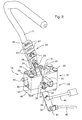
- Fig. 3 the dual lever steering control mechanism is shown with forward/reverse lever 24 pivoted forward on the first axis to turn the corresponding wheel in the forward direction.
- the forward/reverse lever also may be pivoted back to rotate the wheel in the reverse direction.
- the front of the upper housing may include a trough 50 for full speed tracking adjustment bolt 37.
- the full speed tracking adjustment bolt can provide a stop to limit forward pivoting of the forward/reverse lever, thereby providing an adjustable maximum or limit to the forward speed of the mower.
- the full speed tracking adjustment bolt may pass through the upper housing and be threaded to a nut captured in the upper housing. The maximum forward speed of the mower may be adjusted by turning the full speed tracking adjustment bolt to vary the penetration of the bolt through the sloped inner wall of the upper housing.
- the lower part 34 of the forward/reverse lever may be connected at pivot joint 39 to damper 40, and at pivot joint 41 to transmission control rod 42.
- the transmission control rod may be linked to a swash plate on a hydrostatic transmission pump.
- the upper part of the forward/reverse lever, above the pair of cylindrical projections, may include a pair of holes through which a rod or bolt 31 may be inserted to provide a second pivot axis 31 transverse to the first pivot axis.
- the second pivot axis may be generally horizontal.
- the forward/reverse lever may be cast zinc, and may include one or more hollow portions.
- neutral position lever 25 may be pivotably connected to the forward/reverse lever by bolt or rod 31 located at the second pivot axis.
- the neutral position lever may have a hole through a lower part thereof, and bolt or rod 31 may be inserted through the hole and the corresponding holes in the forward/reverse lever.
- the operator can pivot the control lever or stick outwardly to a parked position. This can be done only if the forward/reverse lever is at the neutral position. Pivoting the control lever or stick outwardly causes neutral position lever 25 to pivot on the second pivot axis, so that its lower part enters slot 38 in the upper housing. After the lower part of the neutral position lever enters slot 38, it can contact and actuate safety switch 33.
- the lever and neutral position lever may pivot between about 20 degrees and about 45 degrees to the full outward or parked position.
- the lower end of the neutral position lever may be sloped at the same or similar angle of between about 20 degrees and 45 degrees from vertical, and may assure full contact with the safety switch in the full outward position.
- the neutral position lever may be cast zinc.
- each control lever or stick may be attached and secured to a neutral position lever in any of or a plurality of different settings.
- the different settings of the control lever or stick on the neutral position lever can accommodate different operators, arm lengths, seat positions, and operating conditions.
- each control lever or stick can be attached to the neutral position lever at two or more different height settings. Different height settings can help accommodate operators of different sizes and arm lengths.
- the lower part of the neutral position lever has a plurality of upper slots 27 and lower holes 26. For example, there may be three upper slots 27 spaced about one inch from the slot above or below it.
- the control lever or stick may be attached to the neutral position lever by inserting attachment bolts 29 through the selected holes and slots.
- a pair of attachment bolts 29 may attach the control lever or stick to the neutral position lever, one of the bolts through a lower hole, and one of the bolts through an upper slot.
- a control lever or stick can be attached to the neutral position lever at two or more different fore and aft settings with respect to the operator seat or platform.
- the proximity of the levers or sticks to the operator in the neutral position, and in the forward and reverse positions
- Each of the upper slots in the neutral position lever may be about one inch in length, and may have the shape of an arc with one of holes 26 as its hypothetical center point.
- Each slot may be separated by a ledge 44.
- Detents or ridges 49 in each of the upper slots may help hold an attachment bolt securely in a desired setting. The detents or ridges may prevent the attachment bolt, once tightened, from shifting fore or aft within the slot.
- the forward/reverse lever may be moved to the neutral position.
- An attachment bolt may be inserted through the lever and a selected hole 26.
- the lever then may be placed in a desired fore/aft setting with respect to the operator seat or platform, and the desired height.
- a second attachment bolt may be inserted through the lever and the selected upper slot 27, and the attachment bolts may be tightened.
Landscapes
- Life Sciences & Earth Sciences (AREA)
- Environmental Sciences (AREA)
- Harvester Elements (AREA)
Abstract
Description
- This invention relates to grass mowing machines, and specifically to zero turning radius (ZTR) mowing machines having independently powered left and right drive wheels controlled by a pair of control levers or sticks.
- Grass mowing machines known as ZTR mowers have at least one independently powered drive wheel on each side of a frame. One drive wheel may be operated in a forward direction while the other drive wheel may be stopped or operated in reverse. Many ZTR mowers have a twin stick control system. A pair of control levers or sticks may be provided side-by-side, with each lever or stick controlling one of the drive wheels. When both levers or sticks are advanced together forwardly out of their neutral position, both drive wheels rotate forwardly to cause the mower to move forward. A ZTR mower may be steered by advancing one lever or stick more than the other.
- Typically, each control lever or stick on a ZTR mower may be linked to a pump arm of one of two separate hydraulic pumps, or of a dual hydraulic pump; i.e, a separate pump for each wheel. The lever or stick may be used to move a pump swashplate through a direct linkage.
- The control levers or sticks on a ZTR mower may be mounted on the vehicle frame so that each has a first pivot axis allowing the lever or stick in the operating position to pivot forwardly in an arc to turn the wheel in forward, or pivot rearwardly to turn the wheel in reverse. Additionally, each lever or stick may pivot outwardly in an arc from the operating position to a non-operating or parked position. Some levers or sticks may pivot outwardly to activate a safety switch which can deactivate the PTO and/or cutting blades, to enhance safety of an operator who is exiting or entering the operator seat or platform.
-
US 6,434,917 B1 shows a twin -lever drive wheel steering mower for a sitting operator with each lever independently controlling a brake and the speed of each drive wheel through a separate hydraulic pump and motor transmission. A brake positioned on each drive wheel; a pair of pivotally mounted steering levers, each controlling one of said pumps mounted on the mower for longitudinal movement, each steering lever is connected independently to the swash plate of its controlled pump providing variable speeds forward, reverse, and a neutral zero flow position; linkage members connecting the steering levers for each wheel to said brake on each wheel; a pair of T-shaped slots having a lateral leg in a cover plate surrounding each of the steering levers allowing the levers to move laterally outward in the lateral leg to engage the brakes only in the neutral position. - In the past, the left and right hand control levers or sticks were mounted on a ZTR mower with separate left and right control mechanisms to allow pivoting of the levers. The pivot mechanisms typically were made from sheet steel, rod and tubing, and included a bracket to mount a plunger-type safety switch near the part on the lever that activates the plunger on the switch. Additionally, the control levers or sticks could not be readily sized or mounted to optimize operator comfort. For example, ZTR mowers did not allow adjustment of the height of the control levers and the position of the levers relative to the operator seat or platform.
- There is a need for a light weight, inexpensive, dual lever steering control mechanism for mounting control levers or sticks on ZTR mowers. There is a need for a dual lever steering control mechanism that can be used interchangeably to mount either the left or right control levers or sticks to a ZTR mower. There is a need for a dual lever steering control mechanism having a minimum number of parts and components to simplify manufacturing and assembly. There is a need for a dual lever steering control mechanism that can allow the levers to be safely and securely adjusted up/down and fore/aft for optimal operator comfort.
- It is therefore an object of the present invention to provide a dual lever steering control mechanism lever meeting this need.
- This object is met according to the invention by the teaching of claim 1, while features developing the solution in an advantageous way are set forth in the further claims.
- A dual lever steering control mechanism is provided for mounting control levers or sticks to a ZTR mower. The dual lever steering control mechanism may be used interchangeably to mount either the left hand or right hand control lever or stick, and includes only four cast parts. The mechanism allows adjustment of the lever or stick to change its height setting and position relative to the operator seat or platform, to optimize operator comfort.
- Numerous other advantages and features of the present invention will be become readily apparent from the following detailed description of the invention and the embodiments thereof, from the claims and from the accompanying drawings wherein
- Fig. 1 is a perspective view of a pair of dual lever steering control mechanisms for a ZTR mower according to a first embodiment of the invention.
- Fig. 2 is a perspective view of a dual lever steering control mechanism in a neutral position according to a first embodiment.
- Fig. 3 is a perspective view of a dual lever steering control mechanism in a full forward position according to a first embodiment.
- Fig. 4 is a perspective view of a dual lever steering control mechanism in a parked position according to a first embodiment.
- The present invention may be used with a ZTR mower having at least one drive wheel on each side that is independently powered so that it may rotate independently of the other drive wheel. Each independent drive may include a separate hydrostatic drive motor coupled to each wheel. The pair of drive motors may be connected via hydraulic conduits to a dual hydrostatic pump; i.e, a separate pump for each wheel. Each side of the dual hydrostatic pump may have a swashplate that may define a pump stroke between a neutral position and a full forward position.
- In a first embodiment shown in Fig. 1, left and right motion control levers or
sticks - In one embodiment, the lower ends of each control lever or
stick steering control mechanism 18. The same dual lever steering control mechanism may be used to mount either the left hand or right hand control lever or stick. In the mounted position, each control lever or stick may move independently of the other. For example, in Fig. 1, left control lever orstick 11 is shown in the parked position, and right control lever orstick 12 is shown in the neutral position. - In Fig. 2, dual lever
steering control mechanism 18 is shown in the neutral position. The dual lever steering control mechanism may includeupper housing 21,lower housing 22, forward/reverse lever 24, andneutral position lever 25. The upper and lower housings may be metal components that can be fastened together withbolts 23 at or near theouter walls inner walls opening 51 dimensioned to receive the forward/reverse lever 24 andneutral position lever 25. - Now referring to Fig. 3, the dual lever steering control mechanism is shown in the forward position according to one embodiment. The
inner wall 47 of the upper housing facing the front and rear of the housing may be sloped at an angle that defines and provides a stop for the maximum forward and reverse positions, and maximum pivot angles of forward/reverse lever 24. For example, the slope of the inner walls of the upper housing may be between about 5 degrees and about 30 degrees from vertical. - In one embodiment, the upper housing also may include an landing or
shelf 35 on whichneutral position switch 33 may be mounted. The landing orshelf 35 may be integral with the housing and preferably extends outwardly from the outer wall of the upper housing under slot 38. - In one embodiment, forward/
reverse lever 24 may be inserted and positioned in opening 51. The forward/reverse lever may include a pair ofcylindrical projections 28 near or adjacent the midpoint of the lever. The cylindrical projections may be pivotably mounted incollar 32 between the upper and lower housings. The cylindrical projections define a first, generally horizontal pivot axis on which the forward/reverse lever can pivot fore and aft. - In Fig. 3, the dual lever steering control mechanism is shown with forward/
reverse lever 24 pivoted forward on the first axis to turn the corresponding wheel in the forward direction. The forward/reverse lever also may be pivoted back to rotate the wheel in the reverse direction. - In one embodiment, the front of the upper housing may include a
trough 50 for full speedtracking adjustment bolt 37. The full speed tracking adjustment bolt can provide a stop to limit forward pivoting of the forward/reverse lever, thereby providing an adjustable maximum or limit to the forward speed of the mower. The full speed tracking adjustment bolt may pass through the upper housing and be threaded to a nut captured in the upper housing. The maximum forward speed of the mower may be adjusted by turning the full speed tracking adjustment bolt to vary the penetration of the bolt through the sloped inner wall of the upper housing. - In one embodiment, the
lower part 34 of the forward/reverse lever, below the pair of cylindrical projections, may be connected at pivot joint 39 todamper 40, and at pivot joint 41 totransmission control rod 42. The transmission control rod may be linked to a swash plate on a hydrostatic transmission pump. - In one embodiment, the upper part of the forward/reverse lever, above the pair of cylindrical projections, may include a pair of holes through which a rod or
bolt 31 may be inserted to provide asecond pivot axis 31 transverse to the first pivot axis. For example, the second pivot axis may be generally horizontal. In one embodiment, the forward/reverse lever may be cast zinc, and may include one or more hollow portions. - In one embodiment,
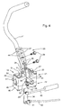
neutral position lever 25 may be pivotably connected to the forward/reverse lever by bolt orrod 31 located at the second pivot axis. The neutral position lever may have a hole through a lower part thereof, and bolt orrod 31 may be inserted through the hole and the corresponding holes in the forward/reverse lever. - In one embodiment, as shown in Fig. 4, the operator can pivot the control lever or stick outwardly to a parked position. This can be done only if the forward/reverse lever is at the neutral position. Pivoting the control lever or stick outwardly causes
neutral position lever 25 to pivot on the second pivot axis, so that its lower part enters slot 38 in the upper housing. After the lower part of the neutral position lever enters slot 38, it can contact and actuatesafety switch 33. The lever and neutral position lever may pivot between about 20 degrees and about 45 degrees to the full outward or parked position. The lower end of the neutral position lever may be sloped at the same or similar angle of between about 20 degrees and 45 degrees from vertical, and may assure full contact with the safety switch in the full outward position. The neutral position lever may be cast zinc. - In one embodiment, each control lever or stick may be attached and secured to a neutral position lever in any of or a plurality of different settings. The different settings of the control lever or stick on the neutral position lever can accommodate different operators, arm lengths, seat positions, and operating conditions.
- In one embodiment, each control lever or stick can be attached to the neutral position lever at two or more different height settings. Different height settings can help accommodate operators of different sizes and arm lengths. To provide different height settings, the lower part of the neutral position lever has a plurality of
upper slots 27 andlower holes 26. For example, there may be threeupper slots 27 spaced about one inch from the slot above or below it. The control lever or stick may be attached to the neutral position lever by insertingattachment bolts 29 through the selected holes and slots. A pair ofattachment bolts 29 may attach the control lever or stick to the neutral position lever, one of the bolts through a lower hole, and one of the bolts through an upper slot. - In one embodiment, a control lever or stick can be attached to the neutral position lever at two or more different fore and aft settings with respect to the operator seat or platform. As a result, the proximity of the levers or sticks to the operator (in the neutral position, and in the forward and reverse positions) can be adjusted to a different setting to accommodate different operators and their ergonomic needs, and to maximize operator comfort and performance. Each of the upper slots in the neutral position lever may be about one inch in length, and may have the shape of an arc with one of
holes 26 as its hypothetical center point. Each slot may be separated by aledge 44. Detents orridges 49 in each of the upper slots may help hold an attachment bolt securely in a desired setting. The detents or ridges may prevent the attachment bolt, once tightened, from shifting fore or aft within the slot. - In one embodiment, to attach a control lever or stick to the neutral position lever, the forward/reverse lever may be moved to the neutral position. An attachment bolt may be inserted through the lever and a selected
hole 26. The lever then may be placed in a desired fore/aft setting with respect to the operator seat or platform, and the desired height. A second attachment bolt may be inserted through the lever and the selectedupper slot 27, and the attachment bolts may be tightened. - Having described the preferred embodiment, it will become apparent that various modifications can be made without departing from the scope of the invention as defined in the accompanying claims.
Claims (9)
- A dual lever steering control mechanism for mounting a control lever (11, 12) to a mower characterized by an upper housing having an outer wall and inner wall, a lower housing (22) removably attached to the upper housing (21) and having an outer wall (48) and an inner wall (47), the inner walls (47) of the upper and lower housings (21, 22) providing an opening (51); a forward/reverse lever (24) insertable through the opening (51) and pivoting on a first axis; and a neutral position lever (25) pivotably attached to the forward/reverse lever (24) to pivot on a second axis (31) transverse to the first axis, the control lever (11) attached to the neutral position lever (25).
- The dual lever steering control mechanism according to claim 1, characterized in that the control lever (11) may be attached to the neutral position lever at a plurality of different height and fore/aft settings wherein the neutral position lever (25) preferably has at least one slot to which the control lever (11) may be attached in a plurality of fore/aft settings.
- The dual lever steering control mechanism according to claim 1 or 2, characterized in wherein the neutral position lever (25) has a plurality of slots (27) to which the control lever (11) may be attached in a plurality of height settings.
- The dual lever steering control mechanism according to claim 3, characterized in that the slots (27) have ridges (49).
- The dual lever steering control mechanism according to on or several of the previous claims, characterized by a neutral position or safety switch (33) activated by pivoting the neutral position lever (25) outwardly.
- The dual lever steering control mechanism according to one or several of the previous claims, characterized by a full speed tracking adjustment bolt (37) in the lower housing (22) to provide an adjustable stop for limiting the pivoting of the forward/reverse lever (24) on the first axis preferably limiting the forward speed of the mower.
- The dual lever steering control mechanism according to one or several of the previous claims, characterized in that the upper housing (21), lower housing (22), forward/reverse lever (24) and neutral position (25) lever are cast metal.
- The dual lever steering control mechanism according to one or several of the previous claims, characterized in that the neutral position lever (25) pivot outwardly on the second pivot axis (31) only if the forward/reverse lever (24) is in the neutral position and that a/the neutral position or safety switch (33) is positioned on the housing (21, 22) actuatable if the neutral position lever (25) pivots outwardly.
- The dual lever steering control mechanism according to claim 8, characterized in that the neutral position or safety switch (33) is mounted to a landing integral (35) with the housing (21, 22).
Applications Claiming Priority (1)
| Application Number | Priority Date | Filing Date | Title |
|---|---|---|---|
| US11/454,774 US7458432B2 (en) | 2006-06-16 | 2006-06-16 | Dual lever steering control mechanism |
Publications (2)
| Publication Number | Publication Date |
|---|---|
| EP1867227A1 true EP1867227A1 (en) | 2007-12-19 |
| EP1867227B1 EP1867227B1 (en) | 2009-10-21 |
Family
ID=38353627
Family Applications (1)
| Application Number | Title | Priority Date | Filing Date |
|---|---|---|---|
| EP07110037A Ceased EP1867227B1 (en) | 2006-06-16 | 2007-06-12 | Dual lever steering control mechanism |
Country Status (3)
| Country | Link |
|---|---|
| US (1) | US7458432B2 (en) |
| EP (1) | EP1867227B1 (en) |
| DE (1) | DE602007002847D1 (en) |
Cited By (3)
| Publication number | Priority date | Publication date | Assignee | Title |
|---|---|---|---|---|
| EP2002703A1 (en) * | 2007-06-12 | 2008-12-17 | Deere & Company | Neutral adjustment mechanism |
| WO2010030281A1 (en) * | 2008-09-12 | 2010-03-18 | Husqvarna U.S. Holding, Inc. | Mower with adjustable hand grips and partially enclosed operator present switch |
| EP2989978A1 (en) | 2014-08-28 | 2016-03-02 | Weinmann Geräte für Medizin GmbH + Co. KG | Artificial respiration device and method for same |
Families Citing this family (37)
| Publication number | Priority date | Publication date | Assignee | Title |
|---|---|---|---|---|
| US8087481B2 (en) * | 2007-08-29 | 2012-01-03 | Deere & Company | Dual lever steering controls with control stops |
| US7708091B2 (en) * | 2008-01-30 | 2010-05-04 | Honda Motor Co., Ltd. | Apparatuses and methods for providing hybrid steering for a vehicle |
| DE102010013169B4 (en) * | 2010-03-27 | 2013-06-20 | Audi Ag | Operating device for a motor vehicle |
| EP2726358A4 (en) * | 2011-06-29 | 2015-07-01 | Husqvarna Ab | Lawn care vehicle adjustable steering assembly |
| US9285028B2 (en) * | 2012-03-19 | 2016-03-15 | Kubota Corporation | Self-propelling work vehicle for forward and reverse drive |
| AT512500B1 (en) * | 2012-04-26 | 2013-09-15 | Wacker Neuson Linz Gmbh | Device for controlling a working machine |
| US8887840B2 (en) * | 2012-08-08 | 2014-11-18 | Swisher Acquisition, Inc. | Zero-turn lawnmower with improved control handles |
| US9510503B2 (en) * | 2012-10-17 | 2016-12-06 | Deere & Company | Grass mowing machine operator platform |
| US20140173946A1 (en) * | 2012-12-20 | 2014-06-26 | Briggs & Stratton Corporation | Zero-turn utility vehicle |
| CN103039183B (en) * | 2013-01-25 | 2015-09-30 | 天佑电器(苏州)有限公司 | The operation controlling organization of garden instrument |
| SE537716C2 (en) * | 2013-06-25 | 2015-10-06 | Steelwrist Ab | Systems, methods and computer programs to control movement of a construction machine's work tools |
| CN103538627A (en) * | 2013-10-30 | 2014-01-29 | 叶呈艳 | Power vehicle with double joysticks controlling front-two-wheel steering |
| US9470305B2 (en) * | 2014-01-24 | 2016-10-18 | Honda Motor Co., Ltd. | Variable speed control systems and methods for walk-behind working machines |
| US9403435B2 (en) | 2014-10-14 | 2016-08-02 | Honda Motor Co., Ltd. | Adjustable ground speed control devices, systems, and methods for walk-behind equipment |
| US9988084B2 (en) | 2015-02-20 | 2018-06-05 | Barreto Manufacturing, Inc. | Controls for vehicles |
| US10414436B1 (en) | 2015-12-29 | 2019-09-17 | Hydro-Gear Limited Partnership | Control assembly for zero turn device |
| US10214869B1 (en) * | 2016-04-28 | 2019-02-26 | Briggs & Stratton Corporation | Outdoor power equipment including electric wheel motors and controls |
| AU2017277925B2 (en) * | 2016-06-10 | 2022-04-14 | Husqvarna Ab | Stand-on lawn care vehicle |
| US10208852B2 (en) * | 2017-04-05 | 2019-02-19 | Kubota Corporation | Steering lever system for work vehicle |
| US10681867B2 (en) | 2018-03-08 | 2020-06-16 | Deere & Company | Zero turning radius mower park brake system |
| US11357170B1 (en) * | 2018-08-24 | 2022-06-14 | Excel Industries, Inc. | Steering lever pivot assembly for terrain working vehicle |
| US11519439B2 (en) | 2018-09-23 | 2022-12-06 | Deere & Company | Quick release lock turnbuckle |
| CN210610341U (en) | 2018-09-27 | 2020-05-26 | 南京德朔实业有限公司 | Lawn mower and blade assembly suitable for lawn mower |
| EP3821692B1 (en) | 2018-09-27 | 2024-07-31 | Nanjing Chervon Industry Co., Ltd. | Lawn mower |
| US11787471B1 (en) | 2019-01-29 | 2023-10-17 | Hydro-Gear Limited Partnership | Control assembly for zero turn vehicle |
| US11091200B2 (en) * | 2019-02-21 | 2021-08-17 | Deere & Company | Zero turning radius mower steering lever modules |
| USD995569S1 (en) | 2019-04-18 | 2023-08-15 | Nanjing Chervon Industry Co., Ltd. | Mower blade assembly |
| CN112449846A (en) * | 2019-09-10 | 2021-03-09 | 丰疆智能科技股份有限公司 | Mower and control mechanism thereof |
| CN112449838A (en) * | 2019-09-10 | 2021-03-09 | 丰疆智能科技股份有限公司 | Mowing machine |
| WO2021069964A1 (en) | 2019-10-11 | 2021-04-15 | Husqvarna Ab | Lawn care vehicle brake system with intuitive control |
| US12268124B2 (en) | 2020-03-11 | 2025-04-08 | Husqvarna Ab | Lawn care vehicle control lever adjustment assembly |
| US12296694B2 (en) | 2021-03-10 | 2025-05-13 | Techtronic Cordless Gp | Lawnmowers |
| USD1014568S1 (en) | 2022-02-14 | 2024-02-13 | Techtronic Cordless Gp | Lawn mower |
| USD1015381S1 (en) | 2022-02-14 | 2024-02-20 | Techtronic Cordless Gp | Lawn mower |
| WO2023215714A1 (en) * | 2022-05-03 | 2023-11-09 | Ariens Company | Control arm for lawn mower controls |
| US12181041B2 (en) | 2022-10-18 | 2024-12-31 | Deere & Company | Zero turning radius mower park brake system |
| US12507624B2 (en) | 2024-04-05 | 2025-12-30 | Kubota Corporation | Adjustable machine handle assembly and mower |
Citations (3)
| Publication number | Priority date | Publication date | Assignee | Title |
|---|---|---|---|---|
| US4470243A (en) * | 1983-12-12 | 1984-09-11 | Sperry Corporation | Combine drive control |
| US5644903A (en) * | 1995-08-30 | 1997-07-08 | Davis, Jr.; Robert D. | Steering control for zero turn radius mower |
| US6434917B1 (en) * | 2001-04-13 | 2002-08-20 | Excel Industries, Inc. | Mower with combined steering and brake levers |
Family Cites Families (11)
| Publication number | Priority date | Publication date | Assignee | Title |
|---|---|---|---|---|
| US4395865A (en) * | 1981-01-28 | 1983-08-02 | Davis Jr Robert D | Self propelled lawn mower |
| IT1196818B (en) * | 1986-02-04 | 1988-11-25 | Fiat Auto Spa | CONTROL DEVICE FOR VEHICLE SPEED CHANGES |
| SE508984C2 (en) * | 1997-12-18 | 1998-11-23 | Scania Cv Ab | Adjusting device for two-piece gear lever |
| US6161637A (en) * | 1998-08-05 | 2000-12-19 | The Toro Company | Twin stick control system |
| US6301864B1 (en) * | 1999-07-22 | 2001-10-16 | Ariens Company | Interlock for lawnmower |
| US6499205B1 (en) * | 2000-09-29 | 2002-12-31 | Caterpillar Inc | Method of converting a control set to obtain various control pattern configurations |
| DE10060803A1 (en) * | 2000-12-07 | 2002-07-04 | Deere & Co | Switching device for a vehicle transmission |
| JP4668439B2 (en) * | 2001-03-12 | 2011-04-13 | 株式会社東海理化電機製作所 | Shift lever device |
| US6709013B2 (en) * | 2001-03-21 | 2004-03-23 | University Of Arkansas | Land vehicle with lever steering |
| US6581704B2 (en) * | 2001-06-21 | 2003-06-24 | Deere & Company | Steering controls |
| US7299610B2 (en) * | 2005-02-10 | 2007-11-27 | Great Plains Manufacturing, Incorporated | Park/drive mechanical interlock system for zero turn radius mowers |
-
2006
- 2006-06-16 US US11/454,774 patent/US7458432B2/en active Active
-
2007
- 2007-06-12 EP EP07110037A patent/EP1867227B1/en not_active Ceased
- 2007-06-12 DE DE602007002847T patent/DE602007002847D1/en active Active
Patent Citations (3)
| Publication number | Priority date | Publication date | Assignee | Title |
|---|---|---|---|---|
| US4470243A (en) * | 1983-12-12 | 1984-09-11 | Sperry Corporation | Combine drive control |
| US5644903A (en) * | 1995-08-30 | 1997-07-08 | Davis, Jr.; Robert D. | Steering control for zero turn radius mower |
| US6434917B1 (en) * | 2001-04-13 | 2002-08-20 | Excel Industries, Inc. | Mower with combined steering and brake levers |
Cited By (8)
| Publication number | Priority date | Publication date | Assignee | Title |
|---|---|---|---|---|
| EP2002703A1 (en) * | 2007-06-12 | 2008-12-17 | Deere & Company | Neutral adjustment mechanism |
| US7634953B2 (en) | 2007-06-12 | 2009-12-22 | Deere & Company | Neutral adjustment mechanism for dual lever steering controls |
| WO2010030281A1 (en) * | 2008-09-12 | 2010-03-18 | Husqvarna U.S. Holding, Inc. | Mower with adjustable hand grips and partially enclosed operator present switch |
| EP2989978A1 (en) | 2014-08-28 | 2016-03-02 | Weinmann Geräte für Medizin GmbH + Co. KG | Artificial respiration device and method for same |
| DE102015009056A1 (en) | 2014-08-28 | 2016-03-03 | Weinmann Geräte für Medizin GmbH + Co. KG | Respirator and procedure for a ventilator |
| US10159810B2 (en) | 2014-08-28 | 2018-12-25 | Loewenstein Medical Technology S.A. | Respiration device and method for a respiration device |
| US11602604B2 (en) | 2014-08-28 | 2023-03-14 | Loewenstein Medical Technology S.A. | Respiration device and method for a respiration device |
| US12053581B2 (en) | 2014-08-28 | 2024-08-06 | Loewenstein Medical Technology S.A. | Respiration device and method for a respiration device |
Also Published As
| Publication number | Publication date |
|---|---|
| DE602007002847D1 (en) | 2009-12-03 |
| US7458432B2 (en) | 2008-12-02 |
| US20070289785A1 (en) | 2007-12-20 |
| EP1867227B1 (en) | 2009-10-21 |
Similar Documents
| Publication | Publication Date | Title |
|---|---|---|
| EP1867227B1 (en) | Dual lever steering control mechanism | |
| EP2002703B1 (en) | Neutral adjustment mechanism | |
| US7306062B2 (en) | Tractor with hydraulic speed and steering control for steering at maximum speed | |
| US7647754B2 (en) | Walk behind lawn mower control system | |
| EP2030497B1 (en) | Dual lever steering controls with control stops | |
| US8047310B2 (en) | Power vehicle incorporating velocity control system | |
| US5913802A (en) | Single lever drivewheel steering power lawn mower | |
| US5507138A (en) | Power mower with riding platform for supporting standing-operator | |
| EP1955580B1 (en) | Dual lever steering control mechanism and grass mowing machine | |
| CA2721118C (en) | Cab suspension for a swather tractor | |
| US8096374B1 (en) | Control system and vehicle incorporating same | |
| US8104552B2 (en) | Control system and vehicle incorporating same | |
| US20080035394A1 (en) | Drive wheel steering system for lawnmower | |
| US6640526B2 (en) | Control assembly for steering lawn mower | |
| US20080277190A1 (en) | Creep Steering Control System Operable From Rearward-Facing Position | |
| US9963065B2 (en) | Zero turn mower light system | |
| US8887840B2 (en) | Zero-turn lawnmower with improved control handles | |
| US20050183409A1 (en) | Control mechanism for zero turning radius mower | |
| CA1271640A (en) | Grass cutting machine | |
| US4126987A (en) | Manual linkage | |
| EP2825016B1 (en) | Cutting deck lift system for lawn mower | |
| GB2627341A (en) | Zero turning radius mower steering sensor linkage | |
| WO2018062996A1 (en) | Adjustable footrest assembly | |
| CA1048906A (en) | Manual linkage | |
| EP1262097A2 (en) | Verge trimming apparatus |
Legal Events
| Date | Code | Title | Description |
|---|---|---|---|
| PUAI | Public reference made under article 153(3) epc to a published international application that has entered the european phase |
Free format text: ORIGINAL CODE: 0009012 |
|
| AK | Designated contracting states |
Kind code of ref document: A1 Designated state(s): AT BE BG CH CY CZ DE DK EE ES FI FR GB GR HU IE IS IT LI LT LU LV MC MT NL PL PT RO SE SI SK TR |
|
| AX | Request for extension of the european patent |
Extension state: AL BA HR MK YU |
|
| 17P | Request for examination filed |
Effective date: 20080619 |
|
| AKX | Designation fees paid |
Designated state(s): DE GB |
|
| GRAP | Despatch of communication of intention to grant a patent |
Free format text: ORIGINAL CODE: EPIDOSNIGR1 |
|
| RIN1 | Information on inventor provided before grant (corrected) |
Inventor name: RESSLER, KYLE Inventor name: MAYER, BENJAMIN |
|
| GRAS | Grant fee paid |
Free format text: ORIGINAL CODE: EPIDOSNIGR3 |
|
| GRAA | (expected) grant |
Free format text: ORIGINAL CODE: 0009210 |
|
| AK | Designated contracting states |
Kind code of ref document: B1 Designated state(s): DE GB |
|
| REG | Reference to a national code |
Ref country code: GB Ref legal event code: FG4D |
|
| REF | Corresponds to: |
Ref document number: 602007002847 Country of ref document: DE Date of ref document: 20091203 Kind code of ref document: P |
|
| PLBE | No opposition filed within time limit |
Free format text: ORIGINAL CODE: 0009261 |
|
| STAA | Information on the status of an ep patent application or granted ep patent |
Free format text: STATUS: NO OPPOSITION FILED WITHIN TIME LIMIT |
|
| 26N | No opposition filed |
Effective date: 20100722 |
|
| PGFP | Annual fee paid to national office [announced via postgrant information from national office to epo] |
Ref country code: DE Payment date: 20190521 Year of fee payment: 13 |
|
| REG | Reference to a national code |
Ref country code: DE Ref legal event code: R119 Ref document number: 602007002847 Country of ref document: DE |
|
| PG25 | Lapsed in a contracting state [announced via postgrant information from national office to epo] |
Ref country code: DE Free format text: LAPSE BECAUSE OF NON-PAYMENT OF DUE FEES Effective date: 20210101 |
|
| PGFP | Annual fee paid to national office [announced via postgrant information from national office to epo] |
Ref country code: GB Payment date: 20230627 Year of fee payment: 17 |
|
| GBPC | Gb: european patent ceased through non-payment of renewal fee |
Effective date: 20240612 |
|
| PG25 | Lapsed in a contracting state [announced via postgrant information from national office to epo] |
Ref country code: GB Free format text: LAPSE BECAUSE OF NON-PAYMENT OF DUE FEES Effective date: 20240612 |