EP1867177B1 - Method and apparatus for antenna mapping selection in mimo-ofdm wireless networks - Google Patents
Method and apparatus for antenna mapping selection in mimo-ofdm wireless networks Download PDFInfo
- Publication number
- EP1867177B1 EP1867177B1 EP20060740853 EP06740853A EP1867177B1 EP 1867177 B1 EP1867177 B1 EP 1867177B1 EP 20060740853 EP20060740853 EP 20060740853 EP 06740853 A EP06740853 A EP 06740853A EP 1867177 B1 EP1867177 B1 EP 1867177B1
- Authority
- EP
- European Patent Office
- Prior art keywords
- wtru
- antenna
- antenna mapping
- calibration
- mapping
- Prior art date
- Legal status (The legal status is an assumption and is not a legal conclusion. Google has not performed a legal analysis and makes no representation as to the accuracy of the status listed.)
- Not-in-force
Links
Images

Classifications
-
- H—ELECTRICITY
- H04—ELECTRIC COMMUNICATION TECHNIQUE
- H04B—TRANSMISSION
- H04B7/00—Radio transmission systems, i.e. using radiation field
- H04B7/02—Diversity systems; Multi-antenna system, i.e. transmission or reception using multiple antennas
- H04B7/04—Diversity systems; Multi-antenna system, i.e. transmission or reception using multiple antennas using two or more spaced independent antennas
- H04B7/0413—MIMO systems
-
- H—ELECTRICITY
- H04—ELECTRIC COMMUNICATION TECHNIQUE
- H04B—TRANSMISSION
- H04B7/00—Radio transmission systems, i.e. using radiation field
- H04B7/02—Diversity systems; Multi-antenna system, i.e. transmission or reception using multiple antennas
- H04B7/04—Diversity systems; Multi-antenna system, i.e. transmission or reception using multiple antennas using two or more spaced independent antennas
- H04B7/06—Diversity systems; Multi-antenna system, i.e. transmission or reception using multiple antennas using two or more spaced independent antennas at the transmitting station
- H04B7/0686—Hybrid systems, i.e. switching and simultaneous transmission
- H04B7/0695—Hybrid systems, i.e. switching and simultaneous transmission using beam selection
-
- H—ELECTRICITY
- H04—ELECTRIC COMMUNICATION TECHNIQUE
- H04B—TRANSMISSION
- H04B7/00—Radio transmission systems, i.e. using radiation field
- H04B7/02—Diversity systems; Multi-antenna system, i.e. transmission or reception using multiple antennas
- H04B7/04—Diversity systems; Multi-antenna system, i.e. transmission or reception using multiple antennas using two or more spaced independent antennas
- H04B7/08—Diversity systems; Multi-antenna system, i.e. transmission or reception using multiple antennas using two or more spaced independent antennas at the receiving station
- H04B7/0868—Hybrid systems, i.e. switching and combining
- H04B7/088—Hybrid systems, i.e. switching and combining using beam selection
Definitions
- the present invention generally relates to wireless communication systems using multiple in-multiple out (MIMO) technology. More particularly, the present invention relates to selecting the optimum transmission settings of a MIMO capable multiple antenna array.
- MIMO multiple in-multiple out
- Wireless communication devices having multiple antennas arranged in a diversity configuration offer a variety of transmission and reception benefits compared to devices with just a single antenna.
- the basis of diversity is that, at any given time, the antenna with the best reception is selected for reception or transmission.
- a device utilizing antenna diversity may have multiple physical antennas, there is only a single set of electronic circuitry to process the signal, also called a radio frequency (RF) chain.
- RF radio frequency
- MIMO wireless technology improves upon antenna diversity by utilizing multiple RF chains.
- Each RF chain is capable of simultaneous reception or transmission. This allows a MIMO device to achieve higher throughput and to resolve negative effects of multipath interference.
- each RF chain is responsible for transmitting a spatial stream. A single frame can be disassembled and multiplexed across multiple spatial streams, which are then reassembled at a receiver.
- MIMO is one of the most promising techniques in wireless communications. Unlike traditional smart antenna techniques that aim to mitigate detrimental multipath fading and enhance robustness of a single data stream, MIMO takes advantage of multipath fading to transmit and receive multiple data streams simultaneously. Theoretically, the capacity in a MIMO system increases linearly with the number of transmit and receive antennas. MIMO is being considered by numerous wireless data communication standards, such as IEEE 802.11n and 3GPP wideband code division, multiple access (WCDMA).
- WCDMA wideband code division, multiple access
- a WTRU may operate in either a spatial multiplexing mode or a spatial diversity mode.
- a WTRU transmits multiple independent data streams to maximize data throughput.
- a WTRU may transmit a single data stream via multiple antennas.
- a WTRU is configured to select an appropriate quality metric or a combination of quality metrics to utilize in the selection of a desired beam combination.
- a WTRU may obtain a calibration matrix (K) in a similar manner.
- K calibration matrix
- Calibration in the context of wireless LANs involves calculating a set of complex-valued correction coefficients that, when multiplied at the transmitting WTRU's baseband streams on a per-antenna and per-sub-carrier basis, would equalize the response difference between transmit and receive processing paths (up to an unknown constant across antennas).
- a transmitting WTRU (Tx WTRU) 110 first needs to calibrate the existing channel between receiving WTRU (Rx WTRU) 120.
- Tx WTRU 110 transmits a calibration training frame (CTF) 131 to Rx WTRU 120.
- Rx WTRU 120 responds by transmitting a sounding physical packet data unit (PPDU) 132.
- PPDU physical packet data unit
- Tx WTRU1 110 calculates a channel estimation H 133 for the channel, referred to as H(2 ⁇ 1).
- Tx WTRU 110 transmits a calibration response 134 which includes the channel estimation H(2 ⁇ 1).
- Rx WTRU 120 then performs channel estimation by transmitting a CTF 135 to Tx WTRU 110.
- Tx WTRU 110 transmits a sounding PPDU 136.
- Rx WTRU 120 calculates a channel estimation H(1 ⁇ 2), and calculates a calibration matrices K(1 ⁇ 2) and K(2 ⁇ 1) for the channel 137.
- Rx WTRU 120 transmits a calibration response 138 including calibration matrix K(1 ⁇ 2) to Tx WTRU 110.
- the calibration matrix K(1 ⁇ 2) is then applied at Tx WTRU1110 as a baseband gain or phase correction factor for transmission to Rx WTRU 120.
- the calibration matrix K(2 ⁇ 1) is applied at Rx WTRU 120, again as a baseband gain/phase correction factor, in Rx WTRU's 120 transmission of signals to Tx WTRU 110.
- the channel is now calibrated and ready for packet exchange.
- Tx TWRU 110 transmits a request 139 to the Rx WTRU 120, which responds by sending modulation and coding scheme (MCS) PPDU 140.
- MCS modulation and coding scheme
- Tx WTRU 110 uses the calibration matrix K(1 ⁇ 2) to calculate a steering matrix V, and packet data transfer 142 begins.
- Smart antennas and beamforming in particular, is a signal processing technique used with arrays of transmitters or receivers that controls the directionality of, or sensitivity to, a radiation pattern.
- beamforming can increase the gain in the direction of wanted signals and decrease the gain in the direction of interference and noise.
- beamforming can increase the gain in the direction the signal is to be sent.
- beamforming capable antennas are combined with MIMO, the number of available antenna mappings dramatically increases.
- EP1063789A1 describes a method for performing a transmitting and receiving antenna diversity in-between a first and a second network device, including using an omni-directional antenna of the first network device to transmit a calibration signal from the first to the second network device, identifying the best receiving antenna of the second network device by antenna switching, and setting the so identified best receiving antenna as the transmitting and receiving antenna of the second network device, using the so set antenna to transmit a calibration signal from the first network device to the second, and identifying the best receiving antenna of the first network device by antenna switching, and setting the so identified best receiving antenna as the transmitting and receiving antenna of the first network device.
- Adaptive MIMO Antenna Selection by I. Berenguer et al., Conference record of the 37th Asilomar conference on signals, systems, and computers, Pacific Groove, CA, Nov. 9 - 12, 2003, IEEE, US, vol. 1, 9 November 2003, p. 21 - 28 , describes discrete stochastic approximation algorithms for selecting an optimal antenna subset based on discrete stochastic optimization techniques, the discrete stochastic approximation algorithms allegedly being used to adaptively select a better antenna subset using criteria such as maximum channel capacity, minimum bounds on error rate, and minimum error rate.
- the present invention is a method and apparatus for selecting an antenna mapping in multiple-in/multiple-out (MIMO) enabled wireless communication networks.
- a candidate set of currently available antenna mappings is determined based upon measured long term channel conditions.
- An antenna mapping is selected from the candidate set, and the mapping is calibrated with a selected antenna mapping of a receiving wireless transmit/receive unit (WTRU).
- WTRU wireless transmit/receive unit
- a calibration training frame CTF is used to calibrate multiple antenna mappings simultaneously or sequentially.
- CTF calibration training frame
- Also disclosed are physical layer and medium access control layer frame formats for implementing antenna mapping selection according to the invention.
- Figure 1 is a signal diagram of a prior art channel calibration and packet data transfer
- Figure 2 is a flow chart of a method for selecting antenna mappings in accordance with a preferred embodiment of the present invention
- FIG. 3 is a block diagram of a system including an AP and a WTRU in accordance with the present invention
- Figures 4A and 4B are a signal timing diagram of channel calibration and packet data transfer where antenna mapping selection in accordance with the present invention is utilized;
- FIG. 5 is a diagram of calibration training frame (CTF) PPDU frame format for implementing antenna mapping selection in accordance with the invention
- Figure 6 is a diagram of a sounding PPDU frame format for implementing antenna mapping selection in accordance with the invention.
- Figure 7 is a diagram of a sounding PPDU MAC frame format for implementing antenna mapping selection in accordance with the invention.
- a wireless transmit/receive unit includes but is not limited to a user equipment, mobile station, fixed or mobile subscriber unit, pager, or any other type of device capable of operating in a wireless environment.
- an access point includes but is not limited to a Node-B, site controller, base station or any other type of interfacing device in a wireless communication environment.
- the term "antenna mapping" means a specific combination of an antenna, or an antenna beam in the case of a beamforming antenna, with a particular RF processing chain.
- a WTRU selects an antenna mapping from a candidate set of currently available antenna mappings, (step 210).
- the WTRU determines if the selected antenna mapping is calibrated, (step 220). If it is determined that the selected antenna mapping is not calibrated, the WTRU calibrates the selected antenna mapping, (step 230). It should be noted that an antenna mapping calibration that has previously been calibrated may become stale. Calibration of the selected antenna mapping is discussed in greater detail below.
- the WTRU determines whether the receiver WTRU has changed its antenna mapping, (step 240).
- the method returns to step 210 to select a new transmitter antenna mapping, if desired. If it is determined that the receiver WTRU has not changed its antenna mapping, the transmitting WTRU begins packet data transmission using the selected and calibrated antenna mapping, (step 250). The method returns to step 210 so that the transmitting WTRU may change its antenna mapping.
- a wireless communication system 300 including a first WTRU 310 and a second WTRU 320 for performing antenna mapping selection in accordance with the present invention is shown.
- the present invention will be explained with reference to downlink transmission from a transmitting WTRU 310 to a receiving WTRU 320.
- the present invention is equally applicable to both uplink and downlink transmissions where either WTRU 310 or WTRU 320 is a base station as well as for configurations where WTRU 310 is in direct communication with WTRU 320 in an ad hoc or mesh network.
- the WTRU 310 includes two RF chains 312A, 312B, a beam selector 314, a plurality of antennas 316A-316n, where n is any integer greater than 1, and a calibration unit 318.
- antennas 316A-316n are capable of generating multiple beams.
- the WTRU 320 includes two RF chains 322A, 322B, a beam selector 324, and a plurality of antennas 326A-326m, where m is any integer greater than 1. Again, in this exemplary embodiment at least one of the antennas 326A-326m is capable of generating multiple beams.
- a beam combination is selected by the beam selector 324 for MIMO transmission and reception in accordance with the presently inventive method 200 described above with reference to Figure 2 .
- the selected antenna mapping is utilized for transmission and reception in accordance with a control signal output from the beam selector 324.
- the beam selector 324 selects a particular beam combination based on quality metrics generated and stored in the calibration unit 328 as explained in detail hereinafter.
- the WTRU components of the present invention may be incorporated into an integrated circuit (IC) or be configured in a circuit comprising a multitude of interconnecting components. It should be understood that while this exemplary embodiment includes two RF chains, this is purely for convenience, and any number of RF chains may be utilized.
- Figure 3 illustrates both transmitting WTRU 310 and receiving WTRU 320 equipped with beamforming antennas, each of which generates three (3) beams.
- the configuration shown in Figure 3 is provided as an example, not as a limitation. Any combination of antenna types having any number of beams, or antennas that are not of the beam-forming or beam-switching type, may be utilized.
- the antennas may be switched parasitic antennas (SPAs), phased array antennas, or any type of directional beam forming antennas.
- a SPA is compact in size, which makes it suitable for WLAN devices. If a SPA is used, a single active antenna element in conjunction with one or more passive antenna elements may be used. By adjusting impedances of the passive antenna elements, the antenna beam pattern may be adjusted and the impedance adjustment may be performed by controlling a set of switches connected to the antenna elements.
- the antennas may be composites including multiple antennas which may all be omni-directional antennas.
- three omni-directional antennas having a selected physical spacing may be used for each of the antennas 326A-326m and the omni-directional antennas may be switched on and off in accordance with a control signal from the beam selector 324 to define different beam combinations.
- Transmitter WTRU 310 (also referred to herein as Tx WTRU) includes two RF chains, 312A, and 312B.
- the beam selector 314 couples several omni-directional antennas 316A-316n to the RF chains 312A, 312B.
- the number of possible antenna mappings for transmitter WTRU 310 is therefore n times the number of RF chains.
- Receiver WTRU 320 (also referred to herein as Rx WTRU) also includes two RF chains, 322A and 322B.
- a beam selector 124 couples several beamforming antennas 326A-326m to the RF chains 322A and 322B.
- each beamforming antenna 326A-326m is capable of forming three directional beams. Therefore, receiver WTRU 120 has a total of m times the number of beams times the number of RF chains antenna mappings.
- the set of all possible antenna mappings that can be employed at any transmitting station is termed the 'superset', and the size of the superset is denoted by N superset .
- N superset may be very large, and it may not be practical to utilize all available antenna mappings at any given time.
- a candidate set is a subset of the superset and is a collection of antenna mappings available for selection at any given time.
- the size of the candidate set is limited to between 8 and 32 antenna mappings.
- a candidate set is not static, but rather it is dynamic and may change over time to reflect changing channel conditions. For example, a transmitting station may monitor the channel conditions of all of the antenna mappings in the current candidate set, either continuously or periodically, and if the measured channel conditions fail to meet a predetermined threshold for a predetermined time, the transmitting station may modify the candidate set. This may be accomplished by discarding several antenna mappings from the current candidate set, introducing several new antenna mappings, and/or retaining several antenna mappings in the candidate set. In high-speed mobility applications, the candidate set may be reduced or selection of an antenna mapping may be stopped altogether.
- WTRU 310 may select any antenna mapping from the candidate set.
- the selection of an antenna mapping is based on long term criterion. No per packet channel tracking is performed, and accordingly, the selection of an antenna mapping does not track fast changes, or micro-structures, of a channel. It should be noted that any changes of the antenna mappings in the candidate set occur outside of any active transmission or reception of data packets.
- the calibration unit 318 of receiving WTRU 310 measures a selected quality metric on each of the antenna beams or beam combinations of the current candidate set and outputs a quality metric measurement data to the beam selector 314.
- the beam selector 314 chooses a desired antenna mapping for data communications with the receiving WTRU 320 based on the quality metric measurement.
- the calibration unit 318 further generates sounding requests for periodic (or aperiodic) calibration as needed, calibration training frames, and sounding PPDUs in response to requests for calibration.
- the calibration unit 318 includes a processor for calculating a channel estimation matrix and a calibration matrix based on received sounding packets, and a memory for storing channel estimation matrices and calibration matrices.
- the calibration unit 318 preferably performs signaling and messaging in compliance with IEEE standards, such as the IEEE 802.11 family of standards, and most preferably the IEEE 802.11n standard.
- PHY Physical
- MAC medium access control
- Preferred quality metrics include, but are not limited to, channel estimations, a signal-to-noise and interference ratio (SNIR), a received signal strength indicator (RSSI), a short-term data throughput, a packet error rate, a data rate, a WTRU operation mode, the magnitude of the maximum eigen-value of the received channel estimation matrix, or the like.
- SNIR signal-to-noise and interference ratio
- RSSI received signal strength indicator
- WTRU operation mode the magnitude of the maximum eigen-value of the received channel estimation matrix, or the like.
- a signal timing diagram 400 of antenna mapping selection is shown in Figures 4A and 4B .
- a first Tx WTRU 410 transmits a sounding PPDU 430 using antenna mapping p to Rx WTRU 420.
- Tx WTRU 410 then transmits a calibration training frame 432 requesting calibration.
- Rx WTRU 420 is currently using antenna mapping x, and replies to the CTF 432 with a sounding PPDU 434 sent using antenna mapping x.
- Tx WTRU 410 performs channel estimation 436 for the antenna mappings in use at both the Tx WTRU 410 and the Rx WTRU 420, namely antenna mapping p and antenna mapping x, respectively.
- a channel estimation matrix is calculated, H ( x ⁇ p ) .
- Tx WTRU 410 transmits a calibration response 438 including the calculated channel estimation.
- the Rx WTRU 420 transmits its own CTF 440 to the Tx WTRU 410.
- Tx WTRU 410 replies with a sounding PPDU 442.
- Rx WTRU 420 uses the sounding PPDU 442 to calculate a channel estimation H ( p ⁇ x) and a calibration matrix for the currently selected antenna mappings, K ( p ⁇ x ) , K ( x ⁇ p ) 444.
- Rx WTRU 420 then transmits a calibration response 446 to Tx WTRU 410 which includes the channel calibration matrix of interest to Tx WTRU 410, namely K ( p ⁇ x). Antenna mapping p ⁇ x is now calibrated, 448.
- Tx WTRU 410 transmits a transmit request (TRQ) 450 to Rx WTRU 420.
- Rx WTRU 420 responds with a sounding PPDU 452 transmitted using antenna mapping x.
- Tx WTRU 410 then calculates a steering matrix V based on the calibration matrix K ( p ⁇ x) 454. Packet data transfer 456 ensues.
- Rx WTRU 420 changes antenna mapping from x to y 458. It is then determined whether antenna mapping p ⁇ y is calibrated. In this exemplary embodiment, the antenna mapping p ⁇ y is not calibrated, and therefore calibration is required.
- Tx WTRU 410 transmits a sounding PPDU 460 on antenna mapping p , and then a CTF 462.
- Rx WTRU 420 replies with a sounding PPDU 464 using antenna mapping y.
- Channel estimation H (y ⁇ p ) 466 occurs at the Tx WTRU 410, and a calibration response 468 is transmitted including the channel estimation.
- the Rx WTRU 420 requests calibration 470, and the Tx WTRU complies with a sounding PPDU 472.
- Rx WTRU 420 calculates channel estimation H(p ⁇ y ) , and calibration matrices K(p ⁇ y ) and K(y ⁇ p), 474.
- a calibration response 476 is then transmitted to the Tx WTRU 410 including the calibration matrix of interest to the Tx WTRU 410.
- the antenna mapping p ⁇ y is now calibrated and ready for data packet exchange, 478.
- Data packet exchange then beings with the Tx WTRU 410 requesting sounding 480, and the Rx WTRU 420 responding with a sounding PPDU 482 transmitted using antenna mapping y .
- a steering matrix V is then calculated based on the calibration K(p ⁇ y ) , and packet data transfer 486 ensues.
- the calibration of multiple antenna mappings occurs in sequence prior to data packet transfer. Similar to the calibration signaling 430 through 448 shown in Figure 4 , a receiving WTRU may respond to CTF using multiple antenna mappings selected from its current candidate set. The resulting calibration matrices may be stored for future reference. For example, a transmitting WTRU may select antenna mapping f , and transmit a CTF to the receiving WTRU requesting calibration. The receiving WTRU may respond sequentially with a sounding PPDU using each antenna mapping q , r , and s , selected from its currently available candidate set.
- Transmitting WTRU calibrates the channel corresponding to antenna mappings f ⁇ q , f ⁇ r , and f ⁇ s, and stores the calibration matrices in memory for future reference prior to packet data transmission. If a receiving WTRU changes its antenna mapping to, for example, antenna mapping r , the transmitting WTRU may retrieve the appropriate calibration matrix from memory and begin data packet transmission without performing calibration again.
- a single sounding PPDU is sent by a transmitting WTRU using a selected antenna mapping, for example mapping b .
- a receiving WTRU having currently available antenna mappings t , u , and v , responds to the single CTF using each of the available antenna mappings t, u , and v, and a calibration matrix is calculated for each antenna mapping b ⁇ t, b ⁇ u, and b ⁇ v . In this manner, the required calibration signaling is reduced thereby decreasing calibration lag and increasing throughput.
- the sounding PPDU includes a modulation control sequence (MCS) bit field.
- MCS bit field is a MAC information element (IE) that indicates the current receiving WTRU antenna mapping candidate set size and currently selected antenna mapping at the receiving WTRU.
- IE MAC information element
- the MCS bit field has a length of 5 bits.
- the MCS bit field includes a one bit 'run length indicator' that permits a transmitting WTRU to request a receiving WTRU to change its current candidate set of antenna mappings.
- a transmitting WTRU may request a receiving WTRU to change its antenna mapping candidate set if the transmitting WTRU is unable to find an antenna mapping at the receiver that satisfies its quality requirements, for example.
- the receiving WTRU if it is able to change its candidate set, it can indicate that it will immediately change its antenna mapping candidate set using a new MAC management frame.
- the transmitting WTRU can indicate a candidate set change to the receiving WTRU by sending a MAC management frame.
- the transmitting WTRU may then immediately change its antenna mapping candidate set and select a suitable antenna mapping from among the mappings in the new candidate set for transmission.
- a transmitting WTRU may request a receiving WTRU to disable completely its antenna mapping. This request may be transmitted to the receiving WTRU in a PPDU. Upon receiving the PPDU with the request, the receiving WTRU may or may not comply with the request. Compliance may be indicated by the receiving WTRU in a sounding PPDU. Where the receiving WTRU complies with the request, the currently selected antenna mapping at the receiving WTRU becomes static and may not change.
- FIG. 5 a diagram of PPDU frame format of a calibration training frame (CTF) PPDU 500 in accordance with an embodiment of the invention is shown.
- a CTF is used to request the transmission of a sounding packet from the receiving WTRU for channel calibration.
- the CTF PPDU 500 has a legacy short-training field (L-STF) 510 followed by a high-throughput long training field (HT-LTF) 520, a high-throughput SIGNAL field (HT-SIG) 530, and a Data field 540.
- L-STF legacy short-training field
- HT-LTF high-throughput long training field
- H-SIG high-throughput SIGNAL field
- the L-STF 510 has the same format as the legacy (pre-802.11n) short training fields.
- the HT-LTF 520 is a field defined in 802.11n PHY and is used with MIMO transmission training.
- the HT-SIG 530 is a field defined in 802.11n and indicates the selected modulation and coding scheme and the size of the MAC service data unit (MSDU).
- the MCS field 535 includes information related to calibration and antenna mapping selection, such as: 1) indication of the selected antenna mapping used in the transmission of the PPDU; 2) indication of a request for full candidate set sounding in series or in parallel; 3) indication of a request to change the size of the candidate set; 4) a run-length bit to request an update of the receiving WTRU's antenna mapping candidate set; and 5) an indication of a request for a receiving WTRU to temporarily hold antenna mapping selection.
- the sounding PPDU 600 includes a legacy short-training field (L-STF) 610, a high-throughput long training field (HT-LTF) 615, a high-throughput SIGNAL field (HT-SIG) 620, a Modulation and Control Sequence (MCS) field 625, followed by a plurality of additional HT-LTFs 630 1 through 630 N , and a Data field 635.
- L-STF legacy short-training field
- HT-LTF high-throughput long training field
- H-SIG high-throughput SIGNAL field
- MCS Modulation and Control Sequence
- the HT-SIG 620 includes two bits that indicate the size of the candidate set and five bits that indicate the total number N of high-throughput long-training fields (HT-LTFs) 630 included in the PPDU. Accordingly, one HT-LTF for each antenna mapping of a candidate set may be included in the PPDU. Preferably, as disclosed above, the candidate size may be as small as 1 and as large as 32.
- Each of the HT-LTFs (615 and 630) in the PPDU is transmitted using a different antenna mapping selected from the candidate set. The selected antenna mapping used in transmitting the first HT-LTF 615 as well as the Data field 635 is indicated in the MCS field 625.
- the MCS field may also include additional bits to indicate: 1) a HOLD/RELEASE request of continued antenna mapping selection at the receiving station; 2) a HOLD/RELEASE confirmation of antenna mapping change in response to a previously received HOLD/RELEASE request; 3) a confirmation of a request previously received in a Calibration Training Frame (CTF) for full candidate set search; and 4) a confirmation of a request previously received in a CTF for a change in the size of the candidate set.
- CTF Calibration Training Frame
- the MAC fields include a Frame Control field 705, a Duration/ID field 710, a receiver address (RA) field 715, a transmitter address (TA) field 720, a MAC service data unit (MSDU) field 725, and a Frame Check Sequence (FCS) field 730.
- the MSDU 725 may include bits that indicate HOLD/RELEASE confirmation of antenna mapping change in response to a received HOLD/RELEASE request, as discussed above with reference to Figure 5 and the MCS field 535.
Abstract
Description
- FIELD OF INVENTION
- The present invention generally relates to wireless communication systems using multiple in-multiple out (MIMO) technology. More particularly, the present invention relates to selecting the optimum transmission settings of a MIMO capable multiple antenna array.
- BACKGROUND
- Wireless communication devices having multiple antennas arranged in a diversity configuration offer a variety of transmission and reception benefits compared to devices with just a single antenna. The basis of diversity is that, at any given time, the antenna with the best reception is selected for reception or transmission. Although a device utilizing antenna diversity may have multiple physical antennas, there is only a single set of electronic circuitry to process the signal, also called a radio frequency (RF) chain.
- Multiple in-multiple out (MIMO) wireless technology improves upon antenna diversity by utilizing multiple RF chains. Each RF chain is capable of simultaneous reception or transmission. This allows a MIMO device to achieve higher throughput and to resolve negative effects of multipath interference. In a transmitting device, each RF chain is responsible for transmitting a spatial stream. A single frame can be disassembled and multiplexed across multiple spatial streams, which are then reassembled at a receiver.
- MIMO is one of the most promising techniques in wireless communications. Unlike traditional smart antenna techniques that aim to mitigate detrimental multipath fading and enhance robustness of a single data stream, MIMO takes advantage of multipath fading to transmit and receive multiple data streams simultaneously. Theoretically, the capacity in a MIMO system increases linearly with the number of transmit and receive antennas. MIMO is being considered by numerous wireless data communication standards, such as IEEE 802.11n and 3GPP wideband code division, multiple access (WCDMA).
- In implementing MIMO, a WTRU may operate in either a spatial multiplexing mode or a spatial diversity mode. In the spatial multiplexing mode, a WTRU transmits multiple independent data streams to maximize data throughput. While in the spatial diversity mode, a WTRU may transmit a single data stream via multiple antennas. Depending on the operation mode, a WTRU is configured to select an appropriate quality metric or a combination of quality metrics to utilize in the selection of a desired beam combination. Typically, an mxN channel matrix H is obtained of the form:

where the subscripts of the elements h represent contributions attributable to each antenna mapping between transmitting WTRU A's antennas a...m and a receiving WTRU N's antennas a...m. - A WTRU may obtain a calibration matrix (K) in a similar manner. Calibration in the context of wireless LANs involves calculating a set of complex-valued correction coefficients that, when multiplied at the transmitting WTRU's baseband streams on a per-antenna and per-sub-carrier basis, would equalize the response difference between transmit and receive processing paths (up to an unknown constant across antennas).
- Referring to
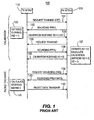
Figure 1 , a signal diagram 100 of prior art channel calibration is shown. A transmitting WTRU (Tx WTRU) 110 first needs to calibrate the existing channel between receiving WTRU (Rx WTRU) 120. Tx WTRU 110 transmits a calibration training frame (CTF) 131 to Rx WTRU 120. Rx WTRU 120 responds by transmitting a sounding physical packet data unit (PPDU) 132. Tx WTRU1 110 calculates achannel estimation H 133 for the channel, referred to as H(2→1). Tx WTRU 110 transmits acalibration response 134 which includes the channel estimation H(2→1). Rx WTRU 120 then performs channel estimation by transmitting aCTF 135 to Tx WTRU 110. In response, Tx WTRU 110 transmits a soundingPPDU 136. Rx WTRU 120 calculates a channel estimation H(1→2), and calculates a calibration matrices K(1→2) and K(2→1) for thechannel 137. Rx WTRU 120 then transmits acalibration response 138 including calibration matrix K(1→2) to Tx WTRU 110. It should be noted that the calibration matrix K(1→2) is then applied at Tx WTRU1110 as a baseband gain or phase correction factor for transmission toRx WTRU 120. The calibration matrix K(2→1) is applied atRx WTRU 120, again as a baseband gain/phase correction factor, in Rx WTRU's 120 transmission of signals toTx WTRU 110. The channel is now calibrated and ready for packet exchange. - To initiate data packet exchange, Tx TWRU 110 transmits a
request 139 to the Rx WTRU 120, which responds by sending modulation and coding scheme (MCS) PPDU 140. Tx WTRU 110 uses the calibration matrix K(1→2) to calculate a steering matrix V, andpacket data transfer 142 begins. - The prior art does not consider the utilization of smart antenna technology. Smart antennas, and beamforming in particular, is a signal processing technique used with arrays of transmitters or receivers that controls the directionality of, or sensitivity to, a radiation pattern. When receiving a signal, beamforming can increase the gain in the direction of wanted signals and decrease the gain in the direction of interference and noise. When transmitting a signal, beamforming can increase the gain in the direction the signal is to be sent. When beamforming capable antennas are combined with MIMO, the number of available antenna mappings dramatically increases.
- When beamforming antennas are included in a WTRU, the number of available antenna mappings may become very large. In order to optimize the communication link between two WTRUs, it is necessary to select the appropriate antenna mapping at both the transmitter and the receiver.
- Therefore, a method and apparatus for efficiently utilizing the variety of available antenna mappings in a MIMO capable wireless device having multiple beamforming antennas is desired.
-
EP1063789A1 describes a method for performing a transmitting and receiving antenna diversity in-between a first and a second network device, including using an omni-directional antenna of the first network device to transmit a calibration signal from the first to the second network device, identifying the best receiving antenna of the second network device by antenna switching, and setting the so identified best receiving antenna as the transmitting and receiving antenna of the second network device, using the so set antenna to transmit a calibration signal from the first network device to the second, and identifying the best receiving antenna of the first network device by antenna switching, and setting the so identified best receiving antenna as the transmitting and receiving antenna of the first network device. - "Adaptive MIMO Antenna Selection" by I. Berenguer et al., Conference record of the 37th Asilomar conference on signals, systems, and computers, Pacific Groove, CA, Nov. 9 - 12, 2003, IEEE, US, vol. 1, 9 November 2003, p. 21 - 28, describes discrete stochastic approximation algorithms for selecting an optimal antenna subset based on discrete stochastic optimization techniques, the discrete stochastic approximation algorithms allegedly being used to adaptively select a better antenna subset using criteria such as maximum channel capacity, minimum bounds on error rate, and minimum error rate.
- SUMMARY
- The present invention is a method and apparatus for selecting an antenna mapping in multiple-in/multiple-out (MIMO) enabled wireless communication networks. A candidate set of currently available antenna mappings is determined based upon measured long term channel conditions. An antenna mapping is selected from the candidate set, and the mapping is calibrated with a selected antenna mapping of a receiving wireless transmit/receive unit (WTRU). When the selected mappings are calibrated, packet data transmission begins. In an alternative embodiment, a calibration training frame (CTF) is used to calibrate multiple antenna mappings simultaneously or sequentially. Also disclosed are physical layer and medium access control layer frame formats for implementing antenna mapping selection according to the invention.
- BRIEF DESCRIPTION OF THE DRAWINGS
- A more detailed understanding of the invention may be had from the following description, given by way of example and to be understood in conjunction with the accompanying drawings, wherein:
-
Figure 1 is a signal diagram of a prior art channel calibration and packet data transfer; -
Figure 2 is a flow chart of a method for selecting antenna mappings in accordance with a preferred embodiment of the present invention; -
Figure 3 is a block diagram of a system including an AP and a WTRU in accordance with the present invention; -
Figures 4A and4B are a signal timing diagram of channel calibration and packet data transfer where antenna mapping selection in accordance with the present invention is utilized; -
Figure 5 is a diagram of calibration training frame (CTF) PPDU frame format for implementing antenna mapping selection in accordance with the invention; -
Figure 6 is a diagram of a sounding PPDU frame format for implementing antenna mapping selection in accordance with the invention; and -
Figure 7 is a diagram of a sounding PPDU MAC frame format for implementing antenna mapping selection in accordance with the invention. - DETAILED DESCRIPTION OF THE PREFERRED EMBODIMENTS
- Although the features and elements of the present invention are described in the preferred embodiments in particular combinations, each feature or element can be used alone (without the other features and elements of the preferred embodiments) or in various combinations with or without other features and elements of the present invention.
- Hereafter, a wireless transmit/receive unit (WTRU) includes but is not limited to a user equipment, mobile station, fixed or mobile subscriber unit, pager, or any other type of device capable of operating in a wireless environment. When referred to hereafter, an access point (AP) includes but is not limited to a Node-B, site controller, base station or any other type of interfacing device in a wireless communication environment. As used herein, the term "antenna mapping" means a specific combination of an antenna, or an antenna beam in the case of a beamforming antenna, with a particular RF processing chain.
- Referring to
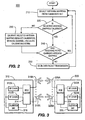
Figure 2 , amethod 200 for antenna mapping selection in accordance with the invention is shown. A WTRU selects an antenna mapping from a candidate set of currently available antenna mappings, (step 210). The WTRU determines if the selected antenna mapping is calibrated, (step 220). If it is determined that the selected antenna mapping is not calibrated, the WTRU calibrates the selected antenna mapping, (step 230). It should be noted that an antenna mapping calibration that has previously been calibrated may become stale. Calibration of the selected antenna mapping is discussed in greater detail below. Next, the WTRU determines whether the receiver WTRU has changed its antenna mapping, (step 240). If the receiving WTRU has changed its antenna mapping, the method returns to step 210 to select a new transmitter antenna mapping, if desired. If it is determined that the receiver WTRU has not changed its antenna mapping, the transmitting WTRU begins packet data transmission using the selected and calibrated antenna mapping, (step 250). The method returns to step 210 so that the transmitting WTRU may change its antenna mapping. - Referring to
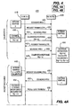
Figure 3 , a wireless communication system 300 including afirst WTRU 310 and asecond WTRU 320 for performing antenna mapping selection in accordance with the present invention is shown. Hereinafter, the present invention will be explained with reference to downlink transmission from a transmittingWTRU 310 to a receivingWTRU 320. However, the present invention is equally applicable to both uplink and downlink transmissions where eitherWTRU 310 orWTRU 320 is a base station as well as for configurations whereWTRU 310 is in direct communication withWTRU 320 in an ad hoc or mesh network. - The
WTRU 310 includes twoRF chains beam selector 314, a plurality ofantennas 316A-316n, where n is any integer greater than 1, and acalibration unit 318. In thisexemplary embodiment antennas 316A-316n are capable of generating multiple beams. TheWTRU 320 includes twoRF chains beam selector 324, and a plurality ofantennas 326A-326m, where m is any integer greater than 1. Again, in this exemplary embodiment at least one of theantennas 326A-326m is capable of generating multiple beams. Referring specifically toWTRU 320, a beam combination is selected by thebeam selector 324 for MIMO transmission and reception in accordance with the presentlyinventive method 200 described above with reference toFigure 2 . The selected antenna mapping is utilized for transmission and reception in accordance with a control signal output from thebeam selector 324. Thebeam selector 324 selects a particular beam combination based on quality metrics generated and stored in thecalibration unit 328 as explained in detail hereinafter. The WTRU components of the present invention may be incorporated into an integrated circuit (IC) or be configured in a circuit comprising a multitude of interconnecting components. It should be understood that while this exemplary embodiment includes two RF chains, this is purely for convenience, and any number of RF chains may be utilized. - For simplicity,
Figure 3 illustrates both transmittingWTRU 310 and receivingWTRU 320 equipped with beamforming antennas, each of which generates three (3) beams. However, the configuration shown inFigure 3 is provided as an example, not as a limitation. Any combination of antenna types having any number of beams, or antennas that are not of the beam-forming or beam-switching type, may be utilized. - The antennas may be switched parasitic antennas (SPAs), phased array antennas, or any type of directional beam forming antennas. A SPA is compact in size, which makes it suitable for WLAN devices. If a SPA is used, a single active antenna element in conjunction with one or more passive antenna elements may be used. By adjusting impedances of the passive antenna elements, the antenna beam pattern may be adjusted and the impedance adjustment may be performed by controlling a set of switches connected to the antenna elements. Alternatively, the antennas may be composites including multiple antennas which may all be omni-directional antennas. For example, three omni-directional antennas having a selected physical spacing may be used for each of the
antennas 326A-326m and the omni-directional antennas may be switched on and off in accordance with a control signal from thebeam selector 324 to define different beam combinations. - To illustrate, reference is made to
Figure 3 . Transmitter WTRU 310 (also referred to herein as Tx WTRU) includes two RF chains, 312A, and 312B. Thebeam selector 314 couples several omni-directional antennas 316A-316n to theRF chains transmitter WTRU 310 is therefore n times the number of RF chains. Receiver WTRU 320 (also referred to herein as Rx WTRU) also includes two RF chains, 322A and 322B. A beam selector 124 couplesseveral beamforming antennas 326A-326m to theRF chains beamforming antenna 326A-326m is capable of forming three directional beams. Therefore,receiver WTRU 120 has a total of m times the number of beams times the number of RF chains antenna mappings. The set of all possible antenna mappings that can be employed at any transmitting station is termed the 'superset', and the size of the superset is denoted by Nsuperset. Nsuperset may be very large, and it may not be practical to utilize all available antenna mappings at any given time. - A candidate set is a subset of the superset and is a collection of antenna mappings available for selection at any given time. Preferably, the size of the candidate set is limited to between 8 and 32 antenna mappings. A candidate set is not static, but rather it is dynamic and may change over time to reflect changing channel conditions. For example, a transmitting station may monitor the channel conditions of all of the antenna mappings in the current candidate set, either continuously or periodically, and if the measured channel conditions fail to meet a predetermined threshold for a predetermined time, the transmitting station may modify the candidate set. This may be accomplished by discarding several antenna mappings from the current candidate set, introducing several new antenna mappings, and/or retaining several antenna mappings in the candidate set. In high-speed mobility applications, the candidate set may be reduced or selection of an antenna mapping may be stopped altogether.
- In a preferred embodiment of the present invention,
WTRU 310 may select any antenna mapping from the candidate set. The selection of an antenna mapping is based on long term criterion. No per packet channel tracking is performed, and accordingly, the selection of an antenna mapping does not track fast changes, or micro-structures, of a channel. It should be noted that any changes of the antenna mappings in the candidate set occur outside of any active transmission or reception of data packets. - Still referring to
Figure 3 , during operation, thecalibration unit 318 of receivingWTRU 310 measures a selected quality metric on each of the antenna beams or beam combinations of the current candidate set and outputs a quality metric measurement data to thebeam selector 314. Thebeam selector 314 chooses a desired antenna mapping for data communications with the receivingWTRU 320 based on the quality metric measurement. Thecalibration unit 318 further generates sounding requests for periodic (or aperiodic) calibration as needed, calibration training frames, and sounding PPDUs in response to requests for calibration. Thecalibration unit 318 includes a processor for calculating a channel estimation matrix and a calibration matrix based on received sounding packets, and a memory for storing channel estimation matrices and calibration matrices. Thecalibration unit 318 preferably performs signaling and messaging in compliance with IEEE standards, such as the IEEE 802.11 family of standards, and most preferably the IEEE 802.11n standard. - Various quality metrics may be used for determining a desired antenna mapping. Physical (PHY) layer, medium access control (MAC) layer or upper layer metrics are suitable. Preferred quality metrics include, but are not limited to, channel estimations, a signal-to-noise and interference ratio (SNIR), a received signal strength indicator (RSSI), a short-term data throughput, a packet error rate, a data rate, a WTRU operation mode, the magnitude of the maximum eigen-value of the received channel estimation matrix, or the like.
- To illustrate the
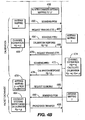
method 200 for antenna mapping selection described with reference toFigure 2 , a signal timing diagram 400 of antenna mapping selection is shown inFigures 4A and4B . Afirst Tx WTRU 410 transmits a soundingPPDU 430 using antenna mapping p toRx WTRU 420.Tx WTRU 410 then transmits acalibration training frame 432 requesting calibration.Rx WTRU 420 is currently using antenna mapping x, and replies to theCTF 432 with a soundingPPDU 434 sent using antenna mapping x.Tx WTRU 410 performschannel estimation 436 for the antenna mappings in use at both theTx WTRU 410 and theRx WTRU 420, namely antenna mapping p and antenna mapping x, respectively. A channel estimation matrix is calculated, H(x→p).Tx WTRU 410 transmits acalibration response 438 including the calculated channel estimation. Next, theRx WTRU 420 transmits itsown CTF 440 to theTx WTRU 410.Tx WTRU 410 replies with a soundingPPDU 442.Rx WTRU 420 uses the soundingPPDU 442 to calculate a channel estimation H(p→x) and a calibration matrix for the currently selected antenna mappings, K(p→x), K(x→p) 444.Rx WTRU 420 then transmits acalibration response 446 toTx WTRU 410 which includes the channel calibration matrix of interest toTx WTRU 410, namely K(p→x). Antenna mapping p→x is now calibrated, 448. - The WTRUs are then free to begin a data packet exchange using the calibrated channel.
Tx WTRU 410 transmits a transmit request (TRQ) 450 toRx WTRU 420.Rx WTRU 420 responds with a soundingPPDU 452 transmitted using antenna mapping x.Tx WTRU 410 then calculates a steering matrix V based on the calibration matrix K(p→x) 454. Packet data transfer 456 ensues. - For a variety of reasons, such as a change in the channel conditions, as measured using a channel quality metric, or mobility of either of the WTRUs, for example,
Rx WTRU 420 changes antenna mapping from x toy 458. It is then determined whether antenna mapping p→y is calibrated. In this exemplary embodiment, the antenna mapping p→y is not calibrated, and therefore calibration is required.Tx WTRU 410 transmits a soundingPPDU 460 on antenna mapping p, and then aCTF 462.Rx WTRU 420 replies with a soundingPPDU 464 using antenna mapping y. Channel estimation H(y→p) 466 occurs at theTx WTRU 410, and acalibration response 468 is transmitted including the channel estimation. TheRx WTRU 420 then requestscalibration 470, and the Tx WTRU complies with a soundingPPDU 472.Rx WTRU 420 calculates channel estimation H(p→y), and calibration matrices K(p→y) and K(y→p), 474. Acalibration response 476 is then transmitted to theTx WTRU 410 including the calibration matrix of interest to theTx WTRU 410. The antenna mapping p→y is now calibrated and ready for data packet exchange, 478. - Data packet exchange then beings with the
Tx WTRU 410 requesting sounding 480, and theRx WTRU 420 responding with a soundingPPDU 482 transmitted using antenna mapping y. A steering matrix V is then calculated based on the calibration K(p→y), and packet data transfer 486 ensues. - In an alternative embodiment, the calibration of multiple antenna mappings occurs in sequence prior to data packet transfer. Similar to the calibration signaling 430 through 448 shown in
Figure 4 , a receiving WTRU may respond to CTF using multiple antenna mappings selected from its current candidate set. The resulting calibration matrices may be stored for future reference. For example, a transmitting WTRU may select antenna mapping f, and transmit a CTF to the receiving WTRU requesting calibration. The receiving WTRU may respond sequentially with a sounding PPDU using each antenna mapping q, r, and s, selected from its currently available candidate set. Transmitting WTRU calibrates the channel corresponding to antenna mappings f→q, f→r, and f→s, and stores the calibration matrices in memory for future reference prior to packet data transmission. If a receiving WTRU changes its antenna mapping to, for example, antenna mapping r, the transmitting WTRU may retrieve the appropriate calibration matrix from memory and begin data packet transmission without performing calibration again. - Alternatively, calibration of multiple antenna mappings may occur in parallel (i.e. simultaneously) thereby reducing signaling. In this embodiment, a single sounding PPDU is sent by a transmitting WTRU using a selected antenna mapping, for example mapping b. A receiving WTRU, having currently available antenna mappings t, u, and v, responds to the single CTF using each of the available antenna mappings t, u, and v, and a calibration matrix is calculated for each antenna mapping b→t, b→u, and b→v. In this manner, the required calibration signaling is reduced thereby decreasing calibration lag and increasing throughput.
- In an alternative embodiment, where the wireless communication system is compliant with the IEEE 802.x standards, the sounding PPDU includes a modulation control sequence (MCS) bit field. This MCS bit field is a MAC information element (IE) that indicates the current receiving WTRU antenna mapping candidate set size and currently selected antenna mapping at the receiving WTRU. Preferably the MCS bit field has a length of 5 bits. Optionally, the MCS bit field includes a one bit 'run length indicator' that permits a transmitting WTRU to request a receiving WTRU to change its current candidate set of antenna mappings.
- A transmitting WTRU may request a receiving WTRU to change its antenna mapping candidate set if the transmitting WTRU is unable to find an antenna mapping at the receiver that satisfies its quality requirements, for example. In this circumstance, if the receiving WTRU is able to change its candidate set, it can indicate that it will immediately change its antenna mapping candidate set using a new MAC management frame.
- When a transmitting WTRU wishes to change its candidate set for any of the various possible reasons (e.g., if the transmitting WTRU is unable to find an antenna mapping of its own from the current candidate set that satisfies its quality requirements), the transmitting WTRU can indicate a candidate set change to the receiving WTRU by sending a MAC management frame. The transmitting WTRU may then immediately change its antenna mapping candidate set and select a suitable antenna mapping from among the mappings in the new candidate set for transmission.
- Alternatively, a transmitting WTRU may request a receiving WTRU to disable completely its antenna mapping. This request may be transmitted to the receiving WTRU in a PPDU. Upon receiving the PPDU with the request, the receiving WTRU may or may not comply with the request. Compliance may be indicated by the receiving WTRU in a sounding PPDU. Where the receiving WTRU complies with the request, the currently selected antenna mapping at the receiving WTRU becomes static and may not change.
- Referring to
Figure 5 , a diagram of PPDU frame format of a calibration training frame (CTF)PPDU 500 in accordance with an embodiment of the invention is shown. It should be noted that while the frame format shown inFigure 5 complies with the IEEE 802.11n standards, the present invention may be applied to any IEEE standards. A CTF is used to request the transmission of a sounding packet from the receiving WTRU for channel calibration. TheCTF PPDU 500 has a legacy short-training field (L-STF) 510 followed by a high-throughput long training field (HT-LTF) 520, a high-throughput SIGNAL field (HT-SIG) 530, and aData field 540. The L-STF 510 has the same format as the legacy (pre-802.11n) short training fields. The HT-LTF 520 is a field defined in 802.11n PHY and is used with MIMO transmission training. The HT-SIG 530 is a field defined in 802.11n and indicates the selected modulation and coding scheme and the size of the MAC service data unit (MSDU). - The
MCS field 535 includes information related to calibration and antenna mapping selection, such as: 1) indication of the selected antenna mapping used in the transmission of the PPDU; 2) indication of a request for full candidate set sounding in series or in parallel; 3) indication of a request to change the size of the candidate set; 4) a run-length bit to request an update of the receiving WTRU's antenna mapping candidate set; and 5) an indication of a request for a receiving WTRU to temporarily hold antenna mapping selection. - Referring to
Figure 6 , a diagram of a soundingPPDU 600 frame format is shown. Again, it should be noted that while the frame format shown complies with the IEEE 802.11n standards, the present invention may be applied to any IEEE standards. The sounding PPDU includes a legacy short-training field (L-STF) 610, a high-throughput long training field (HT-LTF) 615, a high-throughput SIGNAL field (HT-SIG) 620, a Modulation and Control Sequence (MCS)field 625, followed by a plurality of additional HT-LTFs 6301 through 630N, and aData field 635. The HT-SIG 620 includes two bits that indicate the size of the candidate set and five bits that indicate the total number N of high-throughput long-training fields (HT-LTFs) 630 included in the PPDU. Accordingly, one HT-LTF for each antenna mapping of a candidate set may be included in the PPDU. Preferably, as disclosed above, the candidate size may be as small as 1 and as large as 32. Each of the HT-LTFs (615 and 630) in the PPDU is transmitted using a different antenna mapping selected from the candidate set. The selected antenna mapping used in transmitting the first HT-LTF 615 as well as theData field 635 is indicated in theMCS field 625. The MCS field may also include additional bits to indicate: 1) a HOLD/RELEASE request of continued antenna mapping selection at the receiving station; 2) a HOLD/RELEASE confirmation of antenna mapping change in response to a previously received HOLD/RELEASE request; 3) a confirmation of a request previously received in a Calibration Training Frame (CTF) for full candidate set search; and 4) a confirmation of a request previously received in a CTF for a change in the size of the candidate set. - Referring to
Figure 7 , theMAC frame format 700 of the sounding PPDU data frame ofFigure 6 is shown. The MAC fields include aFrame Control field 705, a Duration/ID field 710, a receiver address (RA)field 715, a transmitter address (TA)field 720, a MAC service data unit (MSDU)field 725, and a Frame Check Sequence (FCS)field 730. In one embodiment of the invention, theMSDU 725 may include bits that indicate HOLD/RELEASE confirmation of antenna mapping change in response to a received HOLD/RELEASE request, as discussed above with reference toFigure 5 and theMCS field 535. By reducing candidate set updating, calibration and associated signaling may be reduced thereby increasing throughput.
Claims (26)
- A method for use in a wireless transmit/receive unit, WTRU, for selecting an antenna mapping, wherein an antenna mapping is a combination of a single radio frequency chain selected from a plurality of radio frequency chains and a single antenna beam selected from a plurality of antenna beams, the method characterized by further comprising:adjusting a candidate set of currently available antenna mappings available for selection by the WTRU based on long term channel measurements;selecting an antenna mapping at the WTRU from the candidate set of currently available antenna mappings;determining at the WTRU whether the selected antenna mapping and an antenna mapping of a second WTRU are calibrated;calibrating the selected antenna mapping in response to a determination that the selected antenna mapping is not calibrated; andtransmitting data packets from the WTRU to the second WTRU using the calibrated selected antenna mapping.
- The method of claim 1, wherein the calibrating further comprises:transmitting from the WTRU a calibration training frame, CTF;receiving at the WTRU a sounding physical layer packet data unit, PPDU, in response to the CTF.
- The method of claim 2, wherein the WTRU performs a channel estimation for the selected antenna mapping based on the received PPDU.
- The method of claim 2, further comprising:receiving at the WTRU a sounding PPDU;performing a channel estimation for the selected antenna mapping at the WTRU based on the received PPDU.
- The method of claim 4, further comprising:calculating a calibration matrix of the selected antenna mapping.
- The method of claim 5, wherein the calibration matrix of the selected antenna mapping is used to calculate a steering matrix for data packet transmission.
- The method of claim 1, wherein the WTRU includes at least one beamforming antenna.
- The method of claim 2, wherein the CTF includes a physical layer modulation and coding scheme, MCS, bit field.
- The method of claim 8, wherein the MCS bit field includes an indication of the selected antenna mapping used for transmission of the CTF by the WTRU.
- The method of claim 8, wherein the MCS bit field includes an indication of a request for full candidate set sounding in series or parallel.
- The method of claim 8, wherein the MCS bit field includes a run-length bit for requesting an update of the antenna mapping candidate set of the second WTRU.
- The method of claim 8, wherein the MCS bit field includes a request for temporarily halting antenna mapping selection.
- The method of claim 2, wherein the sounding PPDU includes a plurality of high throughput long training fields, HT-LTFs, one for each antenna mapping of a candidate set to be calibrated.
- The method of claim 13, wherein a plurality of antenna mappings is calibrated sequentially using the plurality of HT-LTFs.
- The method of claim 13, wherein a plurality of antenna mappings is calibrated simultaneously using the plurality of HT-LTFs.
- The method of claim 2, wherein the sounding PPDU includes a medium access control, MAC, layer service data unit, MSDU, bit field.
- The method of claim 16, wherein the MSDU bit field includes a request for continued antenna mapping selection.
- The method of claim 16, wherein the MSDU bit field includes a confirmation of continued antenna mapping selection.
- The method of claim 16, wherein the MSDU bit field includes a confirmation of a request for full antenna mapping candidate set search.
- The method of claim 16, wherein the MSDU bit field includes a confirmation of a request to change the size of an antenna mapping candidate set.
- A multiple-in/multiple-out, MIMO, wireless transmit/receive unit WTRU (320) for selecting an antenna mapping, wherein an antenna mapping is a combination of a single radio frequency chain selected from a plurality of radio frequency chains and a single antenna beam selected from a plurality of antenna beams, the WTRU comprising:a plurality of antennas (326A-326m) including at least one beamforming antenna;a plurality of RF chains (322A, 322B) for signal processing;a beam selector (324) for selectively coupling the plurality of antennas to the plurality of RF chains, the beam selector configured to select an antenna mapping from a candidate set of antenna mappings based on current channel conditions; and characterized bya calibration unit (328) configured for measuring channel conditions and calibrating a channel, and to adjust the candidate set of antenna mappings based on long term channel measurements.
- The WTRU of claim 21, wherein the calibration unit (328) further comprises:a processor for calculating channel estimation matrices, and for calculating calibration matrices based on the calculated channel estimation matrices; anda memory for storing calculated channel estimation matrices and calibration matrices.
- The WTRU of claim 22, wherein the calibration unit (328) is configured to calibrate a plurality of antenna mappings and store the calculated calibration matrices in memory for later use.
- The WTRU of claim 23, wherein the calibration unit (328) is configured to calibrate the plurality of antenna mappings sequentially.
- The WTRU of claim 23, wherein the calibration unit (328) is configured to calibrate the plurality of antenna mappings simultaneously.
- The WTRU of claim 21, wherein the calibration unit (328) is configured to calibrate a channel by calculating a calibration matrix.
Priority Applications (1)
| Application Number | Priority Date | Filing Date | Title |
|---|---|---|---|
| EP10161601.9A EP2207267B1 (en) | 2005-04-07 | 2006-04-07 | Method and apparatus for antenna mapping selection in MIMO-OFDM wireless networks |
Applications Claiming Priority (3)
| Application Number | Priority Date | Filing Date | Title |
|---|---|---|---|
| US66904805P | 2005-04-07 | 2005-04-07 | |
| US11/400,400 US8483200B2 (en) | 2005-04-07 | 2006-04-06 | Method and apparatus for antenna mapping selection in MIMO-OFDM wireless networks |
| PCT/US2006/013464 WO2006110737A2 (en) | 2005-04-07 | 2006-04-07 | Method and apparatus for antenna mapping selection in mimo-ofdm wireless networks |
Related Child Applications (1)
| Application Number | Title | Priority Date | Filing Date |
|---|---|---|---|
| EP10161601.9A Division EP2207267B1 (en) | 2005-04-07 | 2006-04-07 | Method and apparatus for antenna mapping selection in MIMO-OFDM wireless networks |
Publications (3)
| Publication Number | Publication Date |
|---|---|
| EP1867177A2 EP1867177A2 (en) | 2007-12-19 |
| EP1867177A4 EP1867177A4 (en) | 2008-07-02 |
| EP1867177B1 true EP1867177B1 (en) | 2010-05-05 |
Family
ID=37087633
Family Applications (2)
| Application Number | Title | Priority Date | Filing Date |
|---|---|---|---|
| EP20060740853 Not-in-force EP1867177B1 (en) | 2005-04-07 | 2006-04-07 | Method and apparatus for antenna mapping selection in mimo-ofdm wireless networks |
| EP10161601.9A Not-in-force EP2207267B1 (en) | 2005-04-07 | 2006-04-07 | Method and apparatus for antenna mapping selection in MIMO-OFDM wireless networks |
Family Applications After (1)
| Application Number | Title | Priority Date | Filing Date |
|---|---|---|---|
| EP10161601.9A Not-in-force EP2207267B1 (en) | 2005-04-07 | 2006-04-07 | Method and apparatus for antenna mapping selection in MIMO-OFDM wireless networks |
Country Status (18)
| Country | Link |
|---|---|
| US (2) | US8483200B2 (en) |
| EP (2) | EP1867177B1 (en) |
| JP (4) | JP2008536406A (en) |
| CN (2) | CN102185641B (en) |
| AT (1) | ATE467275T1 (en) |
| AU (2) | AU2006235413B2 (en) |
| BR (1) | BRPI0615491A2 (en) |
| CA (1) | CA2604105C (en) |
| DE (1) | DE602006014114D1 (en) |
| DK (1) | DK1867177T3 (en) |
| ES (1) | ES2345218T3 (en) |
| GE (1) | GEP20105003B (en) |
| HK (2) | HK1111297A1 (en) |
| IL (1) | IL186332A0 (en) |
| MX (1) | MX2007012370A (en) |
| NO (1) | NO20075457L (en) |
| SG (2) | SG195526A1 (en) |
| WO (1) | WO2006110737A2 (en) |
Cited By (34)
| Publication number | Priority date | Publication date | Assignee | Title |
|---|---|---|---|---|
| US8767862B2 (en) | 2012-05-29 | 2014-07-01 | Magnolia Broadband Inc. | Beamformer phase optimization for a multi-layer MIMO system augmented by radio distribution network |
| US8774150B1 (en) | 2013-02-13 | 2014-07-08 | Magnolia Broadband Inc. | System and method for reducing side-lobe contamination effects in Wi-Fi access points |
| US8797969B1 (en) | 2013-02-08 | 2014-08-05 | Magnolia Broadband Inc. | Implementing multi user multiple input multiple output (MU MIMO) base station using single-user (SU) MIMO co-located base stations |
| US8811522B2 (en) | 2012-05-29 | 2014-08-19 | Magnolia Broadband Inc. | Mitigating interferences for a multi-layer MIMO system augmented by radio distribution network |
| US8824596B1 (en) | 2013-07-31 | 2014-09-02 | Magnolia Broadband Inc. | System and method for uplink transmissions in time division MIMO RDN architecture |
| US8837650B2 (en) | 2012-05-29 | 2014-09-16 | Magnolia Broadband Inc. | System and method for discrete gain control in hybrid MIMO RF beamforming for multi layer MIMO base station |
| US8842765B2 (en) | 2012-05-29 | 2014-09-23 | Magnolia Broadband Inc. | Beamformer configurable for connecting a variable number of antennas and radio circuits |
| US8861635B2 (en) | 2012-05-29 | 2014-10-14 | Magnolia Broadband Inc. | Setting radio frequency (RF) beamformer antenna weights per data-stream in a multiple-input-multiple-output (MIMO) system |
| US8885757B2 (en) | 2012-05-29 | 2014-11-11 | Magnolia Broadband Inc. | Calibration of MIMO systems with radio distribution networks |
| US8891598B1 (en) | 2013-11-19 | 2014-11-18 | Magnolia Broadband Inc. | Transmitter and receiver calibration for obtaining the channel reciprocity for time division duplex MIMO systems |
| US8923448B2 (en) | 2012-05-29 | 2014-12-30 | Magnolia Broadband Inc. | Using antenna pooling to enhance a MIMO receiver augmented by RF beamforming |
| US8929322B1 (en) | 2013-11-20 | 2015-01-06 | Magnolia Broadband Inc. | System and method for side lobe suppression using controlled signal cancellation |
| US8928528B2 (en) | 2013-02-08 | 2015-01-06 | Magnolia Broadband Inc. | Multi-beam MIMO time division duplex base station using subset of radios |
| US8942134B1 (en) | 2013-11-20 | 2015-01-27 | Magnolia Broadband Inc. | System and method for selective registration in a multi-beam system |
| US8948327B2 (en) | 2012-05-29 | 2015-02-03 | Magnolia Broadband Inc. | System and method for discrete gain control in hybrid MIMO/RF beamforming |
| US8971452B2 (en) | 2012-05-29 | 2015-03-03 | Magnolia Broadband Inc. | Using 3G/4G baseband signals for tuning beamformers in hybrid MIMO RDN systems |
| US8983548B2 (en) | 2013-02-13 | 2015-03-17 | Magnolia Broadband Inc. | Multi-beam co-channel Wi-Fi access point |
| US8989103B2 (en) | 2013-02-13 | 2015-03-24 | Magnolia Broadband Inc. | Method and system for selective attenuation of preamble reception in co-located WI FI access points |
| US8995416B2 (en) | 2013-07-10 | 2015-03-31 | Magnolia Broadband Inc. | System and method for simultaneous co-channel access of neighboring access points |
| US9014066B1 (en) | 2013-11-26 | 2015-04-21 | Magnolia Broadband Inc. | System and method for transmit and receive antenna patterns calibration for time division duplex (TDD) systems |
| US9042276B1 (en) | 2013-12-05 | 2015-05-26 | Magnolia Broadband Inc. | Multiple co-located multi-user-MIMO access points |
| US9060362B2 (en) | 2013-09-12 | 2015-06-16 | Magnolia Broadband Inc. | Method and system for accessing an occupied Wi-Fi channel by a client using a nulling scheme |
| US9065517B2 (en) | 2012-05-29 | 2015-06-23 | Magnolia Broadband Inc. | Implementing blind tuning in hybrid MIMO RF beamforming systems |
| US9088898B2 (en) | 2013-09-12 | 2015-07-21 | Magnolia Broadband Inc. | System and method for cooperative scheduling for co-located access points |
| US9100154B1 (en) | 2014-03-19 | 2015-08-04 | Magnolia Broadband Inc. | Method and system for explicit AP-to-AP sounding in an 802.11 network |
| US9100968B2 (en) | 2013-05-09 | 2015-08-04 | Magnolia Broadband Inc. | Method and system for digital cancellation scheme with multi-beam |
| US9154204B2 (en) | 2012-06-11 | 2015-10-06 | Magnolia Broadband Inc. | Implementing transmit RDN architectures in uplink MIMO systems |
| US9155110B2 (en) | 2013-03-27 | 2015-10-06 | Magnolia Broadband Inc. | System and method for co-located and co-channel Wi-Fi access points |
| US9172446B2 (en) | 2014-03-19 | 2015-10-27 | Magnolia Broadband Inc. | Method and system for supporting sparse explicit sounding by implicit data |
| US9172454B2 (en) | 2013-11-01 | 2015-10-27 | Magnolia Broadband Inc. | Method and system for calibrating a transceiver array |
| US9271176B2 (en) | 2014-03-28 | 2016-02-23 | Magnolia Broadband Inc. | System and method for backhaul based sounding feedback |
| US9294177B2 (en) | 2013-11-26 | 2016-03-22 | Magnolia Broadband Inc. | System and method for transmit and receive antenna patterns calibration for time division duplex (TDD) systems |
| US9425882B2 (en) | 2013-06-28 | 2016-08-23 | Magnolia Broadband Inc. | Wi-Fi radio distribution network stations and method of operating Wi-Fi RDN stations |
| US9497781B2 (en) | 2013-08-13 | 2016-11-15 | Magnolia Broadband Inc. | System and method for co-located and co-channel Wi-Fi access points |
Families Citing this family (112)
| Publication number | Priority date | Publication date | Assignee | Title |
|---|---|---|---|---|
| US9819403B2 (en) | 2004-04-02 | 2017-11-14 | Rearden, Llc | System and method for managing handoff of a client between different distributed-input-distributed-output (DIDO) networks based on detected velocity of the client |
| US10749582B2 (en) | 2004-04-02 | 2020-08-18 | Rearden, Llc | Systems and methods to coordinate transmissions in distributed wireless systems via user clustering |
| US10985811B2 (en) | 2004-04-02 | 2021-04-20 | Rearden, Llc | System and method for distributed antenna wireless communications |
| US9312929B2 (en) | 2004-04-02 | 2016-04-12 | Rearden, Llc | System and methods to compensate for Doppler effects in multi-user (MU) multiple antenna systems (MAS) |
| US8654815B1 (en) | 2004-04-02 | 2014-02-18 | Rearden, Llc | System and method for distributed antenna wireless communications |
| US10886979B2 (en) | 2004-04-02 | 2021-01-05 | Rearden, Llc | System and method for link adaptation in DIDO multicarrier systems |
| US10200094B2 (en) | 2004-04-02 | 2019-02-05 | Rearden, Llc | Interference management, handoff, power control and link adaptation in distributed-input distributed-output (DIDO) communication systems |
| US9826537B2 (en) | 2004-04-02 | 2017-11-21 | Rearden, Llc | System and method for managing inter-cluster handoff of clients which traverse multiple DIDO clusters |
| US11394436B2 (en) | 2004-04-02 | 2022-07-19 | Rearden, Llc | System and method for distributed antenna wireless communications |
| US11309943B2 (en) | 2004-04-02 | 2022-04-19 | Rearden, Llc | System and methods for planned evolution and obsolescence of multiuser spectrum |
| US8542763B2 (en) | 2004-04-02 | 2013-09-24 | Rearden, Llc | Systems and methods to coordinate transmissions in distributed wireless systems via user clustering |
| US10425134B2 (en) | 2004-04-02 | 2019-09-24 | Rearden, Llc | System and methods for planned evolution and obsolescence of multiuser spectrum |
| US10277290B2 (en) | 2004-04-02 | 2019-04-30 | Rearden, Llc | Systems and methods to exploit areas of coherence in wireless systems |
| US11451275B2 (en) | 2004-04-02 | 2022-09-20 | Rearden, Llc | System and method for distributed antenna wireless communications |
| US9685997B2 (en) | 2007-08-20 | 2017-06-20 | Rearden, Llc | Systems and methods to enhance spatial diversity in distributed-input distributed-output wireless systems |
| US8483200B2 (en) * | 2005-04-07 | 2013-07-09 | Interdigital Technology Corporation | Method and apparatus for antenna mapping selection in MIMO-OFDM wireless networks |
| US7486720B2 (en) * | 2005-05-11 | 2009-02-03 | Mitsubishi Electric Research Laboratories, Inc. | Training frames for MIMO stations |
| US20070070934A1 (en) * | 2005-09-28 | 2007-03-29 | Pieter Van Rooyen | Method and system for a reconfigurable OFDM radio supporting diversity |
| US8374096B2 (en) * | 2005-09-30 | 2013-02-12 | Mitsubishi Electric Research Laboratories, Inc. | Method for selecting antennas and beams in MIMO wireless LANs |
| EP2320576A3 (en) * | 2005-09-30 | 2011-12-14 | Mitsubishi Electric Research Laboratories | Training signals for selecting antennas and beams in mimo wireless lans |
| US8068872B2 (en) | 2005-10-06 | 2011-11-29 | Telefonaktiebolaget Lm Ericsson (Publ) | Signaling support for antenna selection using subset lists and subset masks |
| WO2007114804A1 (en) * | 2006-03-30 | 2007-10-11 | Mitsubishi Electric Research Laboratories | Antenna/beam selection training in mimo wireless lans with different sounding frames |
| JP4924106B2 (en) | 2006-04-27 | 2012-04-25 | ソニー株式会社 | Wireless communication system, wireless communication apparatus, and wireless communication method |
| JP4775288B2 (en) | 2006-04-27 | 2011-09-21 | ソニー株式会社 | Wireless communication system, wireless communication apparatus, and wireless communication method |
| JP4356756B2 (en) | 2006-04-27 | 2009-11-04 | ソニー株式会社 | Wireless communication system, wireless communication apparatus, and wireless communication method |
| US8787841B2 (en) * | 2006-06-27 | 2014-07-22 | Qualcomm Incorporated | Method and system for providing beamforming feedback in wireless communication systems |
| JP4837636B2 (en) * | 2006-08-16 | 2011-12-14 | パナソニック株式会社 | MIMO antenna apparatus and wireless communication apparatus including the same |
| EP1892852B1 (en) * | 2006-08-21 | 2010-05-19 | Sony Deutschland Gmbh | Device and method for controlling a selection of antennas in a wireless communication system |
| WO2008069547A1 (en) * | 2006-12-04 | 2008-06-12 | Samsung Electronics Co., Ltd. | Apparatus and method for transmitting/receiving feedback information in a mobile communication system using array antennas |
| CN101548488B (en) * | 2006-12-07 | 2012-10-24 | 三菱电机株式会社 | Radio communication system, radio terminal station, radio base station, and radio communication method |
| US8577303B2 (en) * | 2007-02-05 | 2013-11-05 | Samsung Electronics Co., Ltd. | Apparatus and method for transmitting channel sounding signal in wireless communication system |
| DE602007013686D1 (en) * | 2007-02-07 | 2011-05-19 | Sony Deutschland Gmbh | A method of transmitting a signal in a wireless communication system and communication system |
| US8335248B2 (en) * | 2007-03-21 | 2012-12-18 | Qualcomm Incorporated | Fast square root algorithm for MIMO equalization |
| US8411732B2 (en) * | 2007-03-21 | 2013-04-02 | Qualcomm Incorporated | Fast square root algorithm for MIMO equalization |
| WO2008129114A1 (en) * | 2007-04-23 | 2008-10-30 | Elektrobit Corporation | An improved method for channel sounding and an apparatus using the method |
| JP5235342B2 (en) * | 2007-06-22 | 2013-07-10 | キヤノン株式会社 | Communication apparatus, control method, and program |
| CA3025857C (en) * | 2007-08-20 | 2022-10-18 | Rearden, Llc | System and method for distributed input distributed output wireless communications |
| PL2198664T3 (en) * | 2007-08-31 | 2013-03-29 | Koninl Philips Electronics Nv | Enhanced multi-user transmission |
| US20090092039A1 (en) * | 2007-10-03 | 2009-04-09 | Samsung Electronics Co., Ltd. | Method and system for formation and communication of information frames in wireless communication systems |
| JP5006172B2 (en) * | 2007-12-04 | 2012-08-22 | パナソニック株式会社 | Wireless communication method and wireless communication system |
| WO2009094744A1 (en) * | 2008-02-01 | 2009-08-06 | Nortel Networks Limited | System and method for spatial multiplexing-based multiple antenna broadcast/multicast transmission |
| US8274930B2 (en) * | 2008-03-10 | 2012-09-25 | Mitsubishi Electric Research Laboratories, Inc. | Analog beamforming to reduce interference in WiMAX networks |
| JP4539891B2 (en) * | 2008-08-11 | 2010-09-08 | 岩崎通信機株式会社 | Wireless communication method, wireless communication system, and wireless communication apparatus using multi-antenna |
| US8903019B2 (en) * | 2008-10-29 | 2014-12-02 | Cisco Technology, Inc. | Multidimensional channel estimation without sounding signals |
| JP5403588B2 (en) * | 2009-01-21 | 2014-01-29 | 独立行政法人情報通信研究機構 | Tracking method, wireless communication method, wireless communication program, and information storage medium during wireless communication |
| WO2010095793A1 (en) * | 2009-02-18 | 2010-08-26 | Lg Electronics Inc. | Channel access method for very high throughput (vht) wireless local access network system |
| CN102056220B (en) * | 2009-10-28 | 2014-02-19 | 华为技术有限公司 | Method and device for realizing channel measurement |
| CN102098784B (en) * | 2009-12-14 | 2014-06-04 | 华为技术有限公司 | Resource allocation method and equipment |
| EP2514119A1 (en) * | 2010-02-09 | 2012-10-24 | Siemens Aktiengesellschaft | Method and arrangement for stabilizing a color coding method for optical transmission of data |
| KR101678438B1 (en) | 2010-04-05 | 2016-11-22 | 엘지전자 주식회사 | Transmitter having multiple antennas |
| US8824386B2 (en) | 2010-05-05 | 2014-09-02 | Mediatek Inc. | Method and system of operating a multi-user system |
| KR101497414B1 (en) * | 2010-05-17 | 2015-03-02 | 지멘스 악티엔게젤샤프트 | Method and arrangement for stabilizing a colour coding method for optical transmission of data |
| US9078251B2 (en) * | 2010-10-28 | 2015-07-07 | Lg Electronics Inc. | Method and apparatus for transceiving a data frame in a wireless LAN system |
| TWI420846B (en) * | 2011-01-14 | 2013-12-21 | Realtek Semiconductor Corp | Antenna diversity system |
| JP5866357B2 (en) * | 2011-06-24 | 2016-02-17 | パナソニック インテレクチュアル プロパティ コーポレーション オブアメリカPanasonic Intellectual Property Corporation of America | Transmitting apparatus, transmitting method, receiving apparatus, and receiving method |
| JP2013102272A (en) * | 2011-11-07 | 2013-05-23 | Nippon Telegr & Teleph Corp <Ntt> | Radio communication method and radio communication device |
| US9059750B2 (en) | 2011-11-17 | 2015-06-16 | Cisco Technology, Inc. | Full spatial dimension extraction for implicit beamforming |
| US9071489B2 (en) | 2011-12-07 | 2015-06-30 | Futurewei Technologies, Inc. | System and method for preambles in a wireless communications network |
| US9077415B2 (en) * | 2011-12-19 | 2015-07-07 | Samsung Electronics Co., Ltd. | Apparatus and method for reference symbol transmission in an OFDM system |
| US9178277B1 (en) | 2012-02-01 | 2015-11-03 | Impinj, Inc. | Synthesized-beam RFID reader system with gain compensation and unactivated antenna element coupling suppression |
| JP5435111B2 (en) * | 2012-03-30 | 2014-03-05 | 横河電機株式会社 | COMMUNICATION DEVICE, COMMUNICATION SYSTEM, AND COMMUNICATION METHOD |
| US8599955B1 (en) | 2012-05-29 | 2013-12-03 | Magnolia Broadband Inc. | System and method for distinguishing between antennas in hybrid MIMO RDN systems |
| US8654883B2 (en) * | 2012-05-29 | 2014-02-18 | Magnolia Broadband Inc. | Systems and methods for enhanced RF MIMO system performance |
| US20160352409A1 (en) * | 2012-07-06 | 2016-12-01 | Mediatek Inc. | Method and Wireless Device for Antenna Selection |
| KR102184302B1 (en) * | 2012-11-08 | 2020-11-30 | 삼성전자 주식회사 | Method and apparatus for data transmission and reception in mimo system |
| US11189917B2 (en) | 2014-04-16 | 2021-11-30 | Rearden, Llc | Systems and methods for distributing radioheads |
| US11050468B2 (en) | 2014-04-16 | 2021-06-29 | Rearden, Llc | Systems and methods for mitigating interference within actively used spectrum |
| US11190947B2 (en) | 2014-04-16 | 2021-11-30 | Rearden, Llc | Systems and methods for concurrent spectrum usage within actively used spectrum |
| US10194346B2 (en) | 2012-11-26 | 2019-01-29 | Rearden, Llc | Systems and methods for exploiting inter-cell multiplexing gain in wireless cellular systems via distributed input distributed output technology |
| US10164698B2 (en) | 2013-03-12 | 2018-12-25 | Rearden, Llc | Systems and methods for exploiting inter-cell multiplexing gain in wireless cellular systems via distributed input distributed output technology |
| US9973246B2 (en) | 2013-03-12 | 2018-05-15 | Rearden, Llc | Systems and methods for exploiting inter-cell multiplexing gain in wireless cellular systems via distributed input distributed output technology |
| US10488535B2 (en) | 2013-03-12 | 2019-11-26 | Rearden, Llc | Apparatus and method for capturing still images and video using diffraction coded imaging techniques |
| US9923657B2 (en) | 2013-03-12 | 2018-03-20 | Rearden, Llc | Systems and methods for exploiting inter-cell multiplexing gain in wireless cellular systems via distributed input distributed output technology |
| US9124318B2 (en) | 2013-03-14 | 2015-09-01 | Qualcomm Incorporated | Smart antenna array configuration for multiple-input multiple-output communications |
| RU2767777C2 (en) | 2013-03-15 | 2022-03-21 | Риарден, Ллк | Systems and methods of radio frequency calibration using the principle of reciprocity of channels in wireless communication with distributed input - distributed output |
| CN104243055B (en) * | 2013-06-20 | 2016-06-29 | 华为技术有限公司 | The method of multi-antenna channel correction, device and base station system |
| US9479241B2 (en) | 2013-10-20 | 2016-10-25 | Arbinder Singh Pabla | Wireless system with configurable radio and antenna resources |
| KR101488666B1 (en) * | 2014-01-28 | 2015-02-04 | 서울대학교산학협력단 | Method for transmitting data signal in wireless communication system and method for receiving data signal in wireless communication system |
| EP3127249A1 (en) * | 2014-04-03 | 2017-02-08 | Telefonaktiebolaget LM Ericsson (publ) | Radio network node, method therein, computer program and computer-readable medium comprising the computer program in a wireless communications network |
| US11290162B2 (en) | 2014-04-16 | 2022-03-29 | Rearden, Llc | Systems and methods for mitigating interference within actively used spectrum |
| CN103997761A (en) * | 2014-05-20 | 2014-08-20 | 东南大学 | Optimal frame length selection method of downlink communication of multi-user MIMO system |
| US10237753B2 (en) | 2014-08-11 | 2019-03-19 | Electronics And Telecommunications Research Institute | Method for transmitting frame using selective beamforming and apparatus for performing the method |
| EP3192294B1 (en) * | 2014-09-11 | 2021-03-17 | Telefonaktiebolaget LM Ericsson (publ) | Group based downlink transmission |
| TWI572242B (en) * | 2015-03-20 | 2017-02-21 | 啟碁科技股份有限公司 | Access point and associated anteena selecting method |
| GB2539735A (en) * | 2015-06-25 | 2016-12-28 | Airspan Networks Inc | Sub-sampling antenna elements |
| GB2539734A (en) | 2015-06-25 | 2016-12-28 | Airspan Networks Inc | An antenna apparatus and method of performing spatial nulling within the antenna apparatus |
| GB2539731B (en) | 2015-06-25 | 2021-08-04 | Airspan Ip Holdco Llc | Quality of service in wireless backhauls |
| GB2539730B (en) | 2015-06-25 | 2021-04-07 | Airspan Ip Holdco Llc | Node role assignment in networks |
| WO2016207603A1 (en) | 2015-06-25 | 2016-12-29 | Airspan Networks Inc. | Managing external interference in a wireless network |
| GB2539733A (en) | 2015-06-25 | 2016-12-28 | Airspan Networks Inc | An antenna apparatus and method of configuring a transmission beam for the antenna apparatus |
| GB2539722B (en) | 2015-06-25 | 2021-10-13 | Airspan Ip Holdco Llc | Bearing calculation |
| GB2539736A (en) | 2015-06-25 | 2016-12-28 | Airspan Networks Inc | Wireless network configuration using path loss determination between nodes |
| GB2539727B (en) | 2015-06-25 | 2021-05-12 | Airspan Ip Holdco Llc | A configurable antenna and method of operating such a configurable antenna |
| GB2539732A (en) | 2015-06-25 | 2016-12-28 | Airspan Networks Inc | A configurable antenna and method of operating such a configurable antenna |
| CN106341828B (en) * | 2015-07-10 | 2020-04-03 | 华为技术有限公司 | Channel measurement method and STA |
| TWI720052B (en) * | 2015-11-10 | 2021-03-01 | 美商Idac控股公司 | Wireless transmit/receive unit and wireless communication method |
| US10411776B2 (en) * | 2016-01-14 | 2019-09-10 | Qualcomm Incorporated | Beamforming training using multiple-input and multiple-output transmission scheme |
| US10271220B2 (en) | 2016-02-12 | 2019-04-23 | Microsoft Technology Licensing, Llc | Wireless communication using a central controller |
| US10425179B2 (en) | 2016-09-16 | 2019-09-24 | Altaeros Energies, Inc. | Wireless communication station |
| KR102614380B1 (en) * | 2017-02-08 | 2023-12-15 | 한국전자통신연구원 | Communication method and apparatus using single radio frequency chain antenna |
| KR102447632B1 (en) * | 2017-04-28 | 2022-09-27 | 프라운호퍼 게젤샤프트 쭈르 푀르데룽 데어 안겐반텐 포르슝 에. 베. | Specular component estimation in a wireless communication network |
| CN111213429A (en) | 2017-06-05 | 2020-05-29 | 珠峰网络公司 | Antenna system for multi-radio communication |
| WO2019037847A1 (en) | 2017-08-23 | 2019-02-28 | Fraunhofer-Gesellschaft zur Förderung der angewandten Forschung e.V. | Over the air calibration and testing of beamforming-based multi-antenna devices in anechoic and non-anechoic environments |
| TWI663849B (en) * | 2017-12-04 | 2019-06-21 | 財團法人工業技術研究院 | Beamforming calibration system and method |
| US11050470B1 (en) | 2018-04-25 | 2021-06-29 | Everest Networks, Inc. | Radio using spatial streams expansion with directional antennas |
| US10879627B1 (en) | 2018-04-25 | 2020-12-29 | Everest Networks, Inc. | Power recycling and output decoupling selectable RF signal divider and combiner |
| US11005194B1 (en) | 2018-04-25 | 2021-05-11 | Everest Networks, Inc. | Radio services providing with multi-radio wireless network devices with multi-segment multi-port antenna system |
| US11089595B1 (en) | 2018-04-26 | 2021-08-10 | Everest Networks, Inc. | Interface matrix arrangement for multi-beam, multi-port antenna |
| US10298299B1 (en) * | 2018-05-31 | 2019-05-21 | Quantenna Communications, Inc. | Transmutable MIMO wireless transceiver |
| US11700038B2 (en) * | 2019-05-30 | 2023-07-11 | Cypress Semiconductor Corporation | Enhancement of range and throughput for multi-antenna wireless communications devices |
| US11258470B2 (en) | 2019-07-23 | 2022-02-22 | Semiconductor Components Industries, Llc | Wireless transceiver |
| US20240097774A1 (en) * | 2022-08-16 | 2024-03-21 | Nvidia Corporation | Wireless beam selection |
Family Cites Families (42)
| Publication number | Priority date | Publication date | Assignee | Title |
|---|---|---|---|---|
| JPH07170227A (en) * | 1993-12-16 | 1995-07-04 | Hitachi Ltd | Radio data communication system |
| GB2298338B (en) | 1995-02-15 | 1999-09-29 | Motorola Ltd | A method for reverse channel sounding in a communications system |
| US6049549A (en) * | 1997-08-14 | 2000-04-11 | University Of Massachusetts | Adaptive media control |
| FR2767991B1 (en) * | 1997-09-04 | 1999-10-15 | Alsthom Cge Alcatel | METHOD FOR CALIBRATION OF RECEPTION AND/OR TRANSMISSION CHAINS CONTROLLING A NETWORK OF ACTIVE ANTENNAS, AND CORRESPONDING MOBILE STATION |
| US6075997A (en) | 1997-11-03 | 2000-06-13 | Telefonaktiebolaget L M Ericsson (Publ) | Automatic configuration of antenna near parts equipment |
| US6615024B1 (en) * | 1998-05-01 | 2003-09-02 | Arraycomm, Inc. | Method and apparatus for determining signatures for calibrating a communication station having an antenna array |
| JP3431542B2 (en) * | 1999-06-22 | 2003-07-28 | 株式会社東芝 | Wireless base station |
| EP1063789B1 (en) * | 1999-06-23 | 2007-08-01 | Sony Deutschland GmbH | Transmit and receiving antenna diversity |
| JP2001168789A (en) * | 1999-12-14 | 2001-06-22 | Hitachi Ltd | Variable directivity mobile object communication base station |
| US6351499B1 (en) | 1999-12-15 | 2002-02-26 | Iospan Wireless, Inc. | Method and wireless systems using multiple antennas and adaptive control for maximizing a communication parameter |
| WO2001082500A2 (en) * | 2000-04-22 | 2001-11-01 | Atheros Communications, Inc. | Methods for controlling shared access to wireless transmission systems and increasing throughput of the same |
| US6434375B1 (en) * | 2000-09-13 | 2002-08-13 | Neoreach, Inc. | Smart antenna with no phase calibration for CDMA reverse link |
| GB0029424D0 (en) * | 2000-12-02 | 2001-01-17 | Koninkl Philips Electronics Nv | Radio communication system |
| US6804532B1 (en) * | 2000-12-22 | 2004-10-12 | Cisco Technology, Inc. | System and method for re-routing communications based on wireless communication link quality |
| US6870515B2 (en) * | 2000-12-28 | 2005-03-22 | Nortel Networks Limited | MIMO wireless communication system |
| US6917820B2 (en) * | 2001-01-26 | 2005-07-12 | Stanford University | Method and apparatus for selection and use of optimal antennas in wireless systems |
| JP2002353865A (en) * | 2001-05-23 | 2002-12-06 | Nec Corp | Array antenna transmitter-receiver and its calibration method |
| US7027523B2 (en) * | 2001-06-22 | 2006-04-11 | Qualcomm Incorporated | Method and apparatus for transmitting data in a time division duplexed (TDD) communication system |
| GB0125178D0 (en) | 2001-10-19 | 2001-12-12 | Koninkl Philips Electronics Nv | Method of operating a wireless communication system |
| US6409549B1 (en) * | 2001-10-31 | 2002-06-25 | Hon Hai Precision Ind. Co., Ltd. | Electrical connector |
| US7020110B2 (en) * | 2002-01-08 | 2006-03-28 | Qualcomm Incorporated | Resource allocation for MIMO-OFDM communication systems |
| US20030161410A1 (en) | 2002-02-26 | 2003-08-28 | Martin Smith | Radio communications device with adaptive combination |
| KR100547882B1 (en) * | 2002-02-26 | 2006-02-01 | 삼성전자주식회사 | Method and apparatus for transmitting and receiving status information of forward channel in mobile telecommunication system supporting selective transmit diversity |
| KR100896682B1 (en) * | 2002-04-09 | 2009-05-14 | 삼성전자주식회사 | Mobile communication apparatus and method having transmitting/receiving multiantenna |
| JP2004007242A (en) * | 2002-05-31 | 2004-01-08 | Toshiba Corp | Radio communication equipment and radio communication method |
| US6768715B2 (en) * | 2002-06-07 | 2004-07-27 | Nokia Corporation | Apparatus, and associated method, for performing reverse-link traffic measurements in a radio communication system |
| GB2392065B (en) | 2002-08-15 | 2004-12-29 | Toshiba Res Europ Ltd | Signal decoding methods and apparatus |
| AU2002330691A1 (en) * | 2002-09-06 | 2004-03-29 | Nokia Corporation | Antenna selection method |
| KR20040024455A (en) * | 2002-09-13 | 2004-03-20 | 톰슨 라이센싱 소시에떼 아노님 | Process for controlling an audio/video digital decoder |
| US7151809B2 (en) | 2002-10-25 | 2006-12-19 | Qualcomm, Incorporated | Channel estimation and spatial processing for TDD MIMO systems |
| US8134976B2 (en) | 2002-10-25 | 2012-03-13 | Qualcomm Incorporated | Channel calibration for a time division duplexed communication system |
| US7151951B2 (en) * | 2002-12-23 | 2006-12-19 | Telefonktiebolaget Lm Ericsson (Publ) | Using beamforming and closed loop transmit diversity in a multi-beam antenna system |
| US7392015B1 (en) * | 2003-02-14 | 2008-06-24 | Calamp Corp. | Calibration methods and structures in wireless communications systems |
| US7010329B2 (en) * | 2003-03-11 | 2006-03-07 | Interdigital Technology Corp. | System and method for battery conservation with assistance from the network and radio resource management |
| JP3952404B2 (en) | 2003-05-19 | 2007-08-01 | ソニー株式会社 | Receiver |
| JP2005057497A (en) * | 2003-08-04 | 2005-03-03 | Science Univ Of Tokyo | Radio transmission control method, radio receiving device and radio transmitting device |
| US7664533B2 (en) * | 2003-11-10 | 2010-02-16 | Telefonaktiebolaget Lm Ericsson (Publ) | Method and apparatus for a multi-beam antenna system |
| US7440777B2 (en) * | 2004-08-13 | 2008-10-21 | Broadcom Corporation | Multi-transceiver system with MIMO and beam-forming capability |
| US7289770B2 (en) * | 2004-09-28 | 2007-10-30 | Intel Corporation | Compact feedback for closed loop MIMO |
| US7719993B2 (en) * | 2004-12-30 | 2010-05-18 | Intel Corporation | Downlink transmit beamforming |
| US8483200B2 (en) * | 2005-04-07 | 2013-07-09 | Interdigital Technology Corporation | Method and apparatus for antenna mapping selection in MIMO-OFDM wireless networks |
| KR101099881B1 (en) * | 2006-09-06 | 2011-12-28 | 고려대학교 산학협력단 | Method and apparatus for antenna selecting based on orthogonalized spatial multiplexing system |
-
2006
- 2006-04-06 US US11/400,400 patent/US8483200B2/en not_active Expired - Fee Related
- 2006-04-07 JP JP2008505640A patent/JP2008536406A/en active Pending
- 2006-04-07 SG SG2013074588A patent/SG195526A1/en unknown
- 2006-04-07 MX MX2007012370A patent/MX2007012370A/en active IP Right Grant
- 2006-04-07 EP EP20060740853 patent/EP1867177B1/en not_active Not-in-force
- 2006-04-07 DK DK06740853T patent/DK1867177T3/en active
- 2006-04-07 CN CN2011101061117A patent/CN102185641B/en not_active Expired - Fee Related
- 2006-04-07 AU AU2006235413A patent/AU2006235413B2/en not_active Ceased
- 2006-04-07 CN CN201110100065XA patent/CN102208933A/en active Pending
- 2006-04-07 DE DE200660014114 patent/DE602006014114D1/en active Active
- 2006-04-07 AT AT06740853T patent/ATE467275T1/en not_active IP Right Cessation
- 2006-04-07 EP EP10161601.9A patent/EP2207267B1/en not_active Not-in-force
- 2006-04-07 CA CA 2604105 patent/CA2604105C/en not_active Expired - Fee Related
- 2006-04-07 GE GEAP200610359A patent/GEP20105003B/en unknown
- 2006-04-07 BR BRPI0615491-3A patent/BRPI0615491A2/en not_active IP Right Cessation
- 2006-04-07 WO PCT/US2006/013464 patent/WO2006110737A2/en active Application Filing
- 2006-04-07 SG SG201002392-7A patent/SG161241A1/en unknown
- 2006-04-07 ES ES06740853T patent/ES2345218T3/en active Active
-
2007
- 2007-10-07 IL IL186332A patent/IL186332A0/en unknown
- 2007-10-29 NO NO20075457A patent/NO20075457L/en not_active Application Discontinuation
-
2008
- 2008-05-30 HK HK08106055A patent/HK1111297A1/en not_active IP Right Cessation
-
2010
- 2010-01-22 AU AU2010200245A patent/AU2010200245B8/en not_active Ceased
-
2011
- 2011-12-26 JP JP2011284474A patent/JP2012120184A/en active Pending
-
2012
- 2012-02-24 HK HK12101893A patent/HK1161449A1/en not_active IP Right Cessation
-
2013
- 2013-07-08 US US13/936,601 patent/US9178580B2/en not_active Expired - Fee Related
- 2013-12-02 JP JP2013249420A patent/JP2014099861A/en active Pending
-
2014
- 2014-10-01 JP JP2014203360A patent/JP2015046893A/en active Pending
Cited By (41)
| Publication number | Priority date | Publication date | Assignee | Title |
|---|---|---|---|---|
| US8948327B2 (en) | 2012-05-29 | 2015-02-03 | Magnolia Broadband Inc. | System and method for discrete gain control in hybrid MIMO/RF beamforming |
| US9065517B2 (en) | 2012-05-29 | 2015-06-23 | Magnolia Broadband Inc. | Implementing blind tuning in hybrid MIMO RF beamforming systems |
| US8971452B2 (en) | 2012-05-29 | 2015-03-03 | Magnolia Broadband Inc. | Using 3G/4G baseband signals for tuning beamformers in hybrid MIMO RDN systems |
| US8811522B2 (en) | 2012-05-29 | 2014-08-19 | Magnolia Broadband Inc. | Mitigating interferences for a multi-layer MIMO system augmented by radio distribution network |
| US8767862B2 (en) | 2012-05-29 | 2014-07-01 | Magnolia Broadband Inc. | Beamformer phase optimization for a multi-layer MIMO system augmented by radio distribution network |
| US8837650B2 (en) | 2012-05-29 | 2014-09-16 | Magnolia Broadband Inc. | System and method for discrete gain control in hybrid MIMO RF beamforming for multi layer MIMO base station |
| US8842765B2 (en) | 2012-05-29 | 2014-09-23 | Magnolia Broadband Inc. | Beamformer configurable for connecting a variable number of antennas and radio circuits |
| US8861635B2 (en) | 2012-05-29 | 2014-10-14 | Magnolia Broadband Inc. | Setting radio frequency (RF) beamformer antenna weights per data-stream in a multiple-input-multiple-output (MIMO) system |
| US8885757B2 (en) | 2012-05-29 | 2014-11-11 | Magnolia Broadband Inc. | Calibration of MIMO systems with radio distribution networks |
| US9344168B2 (en) | 2012-05-29 | 2016-05-17 | Magnolia Broadband Inc. | Beamformer phase optimization for a multi-layer MIMO system augmented by radio distribution network |
| US8923448B2 (en) | 2012-05-29 | 2014-12-30 | Magnolia Broadband Inc. | Using antenna pooling to enhance a MIMO receiver augmented by RF beamforming |
| US9154204B2 (en) | 2012-06-11 | 2015-10-06 | Magnolia Broadband Inc. | Implementing transmit RDN architectures in uplink MIMO systems |
| US8928528B2 (en) | 2013-02-08 | 2015-01-06 | Magnolia Broadband Inc. | Multi-beam MIMO time division duplex base station using subset of radios |
| US9300378B2 (en) | 2013-02-08 | 2016-03-29 | Magnolia Broadband Inc. | Implementing multi user multiple input multiple output (MU MIMO) base station using single-user (SU) MIMO co-located base stations |
| US8797969B1 (en) | 2013-02-08 | 2014-08-05 | Magnolia Broadband Inc. | Implementing multi user multiple input multiple output (MU MIMO) base station using single-user (SU) MIMO co-located base stations |
| US9343808B2 (en) | 2013-02-08 | 2016-05-17 | Magnotod Llc | Multi-beam MIMO time division duplex base station using subset of radios |
| US8989103B2 (en) | 2013-02-13 | 2015-03-24 | Magnolia Broadband Inc. | Method and system for selective attenuation of preamble reception in co-located WI FI access points |
| US9385793B2 (en) | 2013-02-13 | 2016-07-05 | Magnolia Broadband Inc. | Multi-beam co-channel Wi-Fi access point |
| US8983548B2 (en) | 2013-02-13 | 2015-03-17 | Magnolia Broadband Inc. | Multi-beam co-channel Wi-Fi access point |
| US8774150B1 (en) | 2013-02-13 | 2014-07-08 | Magnolia Broadband Inc. | System and method for reducing side-lobe contamination effects in Wi-Fi access points |
| US9155110B2 (en) | 2013-03-27 | 2015-10-06 | Magnolia Broadband Inc. | System and method for co-located and co-channel Wi-Fi access points |
| US9100968B2 (en) | 2013-05-09 | 2015-08-04 | Magnolia Broadband Inc. | Method and system for digital cancellation scheme with multi-beam |
| US9425882B2 (en) | 2013-06-28 | 2016-08-23 | Magnolia Broadband Inc. | Wi-Fi radio distribution network stations and method of operating Wi-Fi RDN stations |
| US9313805B2 (en) | 2013-07-10 | 2016-04-12 | Magnolia Broadband Inc. | System and method for simultaneous co-channel access of neighboring access points |
| US8995416B2 (en) | 2013-07-10 | 2015-03-31 | Magnolia Broadband Inc. | System and method for simultaneous co-channel access of neighboring access points |
| US8824596B1 (en) | 2013-07-31 | 2014-09-02 | Magnolia Broadband Inc. | System and method for uplink transmissions in time division MIMO RDN architecture |
| US9497781B2 (en) | 2013-08-13 | 2016-11-15 | Magnolia Broadband Inc. | System and method for co-located and co-channel Wi-Fi access points |
| US9060362B2 (en) | 2013-09-12 | 2015-06-16 | Magnolia Broadband Inc. | Method and system for accessing an occupied Wi-Fi channel by a client using a nulling scheme |
| US9088898B2 (en) | 2013-09-12 | 2015-07-21 | Magnolia Broadband Inc. | System and method for cooperative scheduling for co-located access points |
| US9172454B2 (en) | 2013-11-01 | 2015-10-27 | Magnolia Broadband Inc. | Method and system for calibrating a transceiver array |
| US9236998B2 (en) | 2013-11-19 | 2016-01-12 | Magnolia Broadband Inc. | Transmitter and receiver calibration for obtaining the channel reciprocity for time division duplex MIMO systems |
| US8891598B1 (en) | 2013-11-19 | 2014-11-18 | Magnolia Broadband Inc. | Transmitter and receiver calibration for obtaining the channel reciprocity for time division duplex MIMO systems |
| US9332519B2 (en) | 2013-11-20 | 2016-05-03 | Magnolia Broadband Inc. | System and method for selective registration in a multi-beam system |
| US8942134B1 (en) | 2013-11-20 | 2015-01-27 | Magnolia Broadband Inc. | System and method for selective registration in a multi-beam system |
| US8929322B1 (en) | 2013-11-20 | 2015-01-06 | Magnolia Broadband Inc. | System and method for side lobe suppression using controlled signal cancellation |
| US9294177B2 (en) | 2013-11-26 | 2016-03-22 | Magnolia Broadband Inc. | System and method for transmit and receive antenna patterns calibration for time division duplex (TDD) systems |
| US9014066B1 (en) | 2013-11-26 | 2015-04-21 | Magnolia Broadband Inc. | System and method for transmit and receive antenna patterns calibration for time division duplex (TDD) systems |
| US9042276B1 (en) | 2013-12-05 | 2015-05-26 | Magnolia Broadband Inc. | Multiple co-located multi-user-MIMO access points |
| US9172446B2 (en) | 2014-03-19 | 2015-10-27 | Magnolia Broadband Inc. | Method and system for supporting sparse explicit sounding by implicit data |
| US9100154B1 (en) | 2014-03-19 | 2015-08-04 | Magnolia Broadband Inc. | Method and system for explicit AP-to-AP sounding in an 802.11 network |
| US9271176B2 (en) | 2014-03-28 | 2016-02-23 | Magnolia Broadband Inc. | System and method for backhaul based sounding feedback |
Also Published As
Similar Documents
| Publication | Publication Date | Title |
|---|---|---|
| EP1867177B1 (en) | Method and apparatus for antenna mapping selection in mimo-ofdm wireless networks | |
| KR101381458B1 (en) | Method and apparatus for antenna mapping selection in mimo-ofdm wireless networks | |
| CA2598477A1 (en) | Method and apparatus for selecting a beam combination of multiple-input multiple-output antennas | |
| WO2006031506A1 (en) | Calibration in mimo systems | |
| CN101124734A (en) | Method and apparatus for selecting a beam combination of multiple-input multiple-output antennas | |
| KR200430280Y1 (en) | Multiple-in/multiple-out(mimo) wireless transmit/receive unit(wtru) for optimizing antenna mappings | |
| AU2013270503A1 (en) | Method and Apparatus for Antenna Mapping Selection in MIMO-OFDM Wireless Networks |
Legal Events
| Date | Code | Title | Description |
|---|---|---|---|
| PUAI | Public reference made under article 153(3) epc to a published international application that has entered the european phase |
Free format text: ORIGINAL CODE: 0009012 |
|
| 17P | Request for examination filed |
Effective date: 20071022 |
|
| AK | Designated contracting states |
Kind code of ref document: A2 Designated state(s): AT BE BG CH CY CZ DE DK EE ES FI FR GB GR HU IE IS IT LI LT LU LV MC NL PL PT RO SE SI SK TR |
|
| AX | Request for extension of the european patent |
Extension state: AL BA HR MK YU |
|
| A4 | Supplementary search report drawn up and despatched |
Effective date: 20080530 |
|
| RIC1 | Information provided on ipc code assigned before grant |
Ipc: H04B 7/06 20060101ALN20080526BHEP Ipc: H04B 7/08 20060101ALN20080526BHEP Ipc: H04B 1/00 20060101ALI20080526BHEP Ipc: H04B 7/04 20060101ALI20080526BHEP Ipc: H04Q 7/00 20060101AFI20071024BHEP |
|
| DAX | Request for extension of the european patent (deleted) | ||
| 17Q | First examination report despatched |
Effective date: 20080918 |
|
| GRAP | Despatch of communication of intention to grant a patent |
Free format text: ORIGINAL CODE: EPIDOSNIGR1 |
|
| RIC1 | Information provided on ipc code assigned before grant |
Ipc: H04B 7/06 20060101ALN20091202BHEP Ipc: H04B 7/04 20060101ALI20091202BHEP Ipc: H04B 1/00 20060101AFI20091202BHEP Ipc: H04B 7/08 20060101ALN20091202BHEP |
|
| GRAS | Grant fee paid |
Free format text: ORIGINAL CODE: EPIDOSNIGR3 |
|
| GRAA | (expected) grant |
Free format text: ORIGINAL CODE: 0009210 |
|
| AK | Designated contracting states |
Kind code of ref document: B1 Designated state(s): AT BE BG CH CY CZ DE DK EE ES FI FR GB GR HU IE IS IT LI LT LU LV MC NL PL PT RO SE SI SK TR |
|
| REG | Reference to a national code |
Ref country code: GB Ref legal event code: FG4D |
|
| REG | Reference to a national code |
Ref country code: CH Ref legal event code: EP |
|
| REG | Reference to a national code |
Ref country code: IE Ref legal event code: FG4D |
|
| REF | Corresponds to: |
Ref document number: 602006014114 Country of ref document: DE Date of ref document: 20100617 Kind code of ref document: P |
|
| REG | Reference to a national code |
Ref country code: NL Ref legal event code: T3 |
|
| REG | Reference to a national code |
Ref country code: DK Ref legal event code: T3 |
|
| REG | Reference to a national code |
Ref country code: SE Ref legal event code: TRGR |
|
| REG | Reference to a national code |
Ref country code: ES Ref legal event code: FG2A Ref document number: 2345218 Country of ref document: ES Kind code of ref document: T3 |
|
| LTIE | Lt: invalidation of european patent or patent extension |
Effective date: 20100505 |
|
| PG25 | Lapsed in a contracting state [announced via postgrant information from national office to epo] |
Ref country code: LT Free format text: LAPSE BECAUSE OF FAILURE TO SUBMIT A TRANSLATION OF THE DESCRIPTION OR TO PAY THE FEE WITHIN THE PRESCRIBED TIME-LIMIT Effective date: 20100505 |
|
| PG25 | Lapsed in a contracting state [announced via postgrant information from national office to epo] |
Ref country code: AT Free format text: LAPSE BECAUSE OF FAILURE TO SUBMIT A TRANSLATION OF THE DESCRIPTION OR TO PAY THE FEE WITHIN THE PRESCRIBED TIME-LIMIT Effective date: 20100505 Ref country code: LV Free format text: LAPSE BECAUSE OF FAILURE TO SUBMIT A TRANSLATION OF THE DESCRIPTION OR TO PAY THE FEE WITHIN THE PRESCRIBED TIME-LIMIT Effective date: 20100505 Ref country code: IS Free format text: LAPSE BECAUSE OF FAILURE TO SUBMIT A TRANSLATION OF THE DESCRIPTION OR TO PAY THE FEE WITHIN THE PRESCRIBED TIME-LIMIT Effective date: 20100905 Ref country code: SI Free format text: LAPSE BECAUSE OF FAILURE TO SUBMIT A TRANSLATION OF THE DESCRIPTION OR TO PAY THE FEE WITHIN THE PRESCRIBED TIME-LIMIT Effective date: 20100505 |
|
| PG25 | Lapsed in a contracting state [announced via postgrant information from national office to epo] |
Ref country code: CY Free format text: LAPSE BECAUSE OF FAILURE TO SUBMIT A TRANSLATION OF THE DESCRIPTION OR TO PAY THE FEE WITHIN THE PRESCRIBED TIME-LIMIT Effective date: 20100519 Ref country code: GR Free format text: LAPSE BECAUSE OF FAILURE TO SUBMIT A TRANSLATION OF THE DESCRIPTION OR TO PAY THE FEE WITHIN THE PRESCRIBED TIME-LIMIT Effective date: 20100806 Ref country code: PL Free format text: LAPSE BECAUSE OF FAILURE TO SUBMIT A TRANSLATION OF THE DESCRIPTION OR TO PAY THE FEE WITHIN THE PRESCRIBED TIME-LIMIT Effective date: 20100505 |
|
| PG25 | Lapsed in a contracting state [announced via postgrant information from national office to epo] |
Ref country code: EE Free format text: LAPSE BECAUSE OF FAILURE TO SUBMIT A TRANSLATION OF THE DESCRIPTION OR TO PAY THE FEE WITHIN THE PRESCRIBED TIME-LIMIT Effective date: 20100505 Ref country code: PT Free format text: LAPSE BECAUSE OF FAILURE TO SUBMIT A TRANSLATION OF THE DESCRIPTION OR TO PAY THE FEE WITHIN THE PRESCRIBED TIME-LIMIT Effective date: 20100906 |
|
| PG25 | Lapsed in a contracting state [announced via postgrant information from national office to epo] |
Ref country code: CZ Free format text: LAPSE BECAUSE OF FAILURE TO SUBMIT A TRANSLATION OF THE DESCRIPTION OR TO PAY THE FEE WITHIN THE PRESCRIBED TIME-LIMIT Effective date: 20100505 Ref country code: BE Free format text: LAPSE BECAUSE OF FAILURE TO SUBMIT A TRANSLATION OF THE DESCRIPTION OR TO PAY THE FEE WITHIN THE PRESCRIBED TIME-LIMIT Effective date: 20100505 Ref country code: SK Free format text: LAPSE BECAUSE OF FAILURE TO SUBMIT A TRANSLATION OF THE DESCRIPTION OR TO PAY THE FEE WITHIN THE PRESCRIBED TIME-LIMIT Effective date: 20100505 Ref country code: RO Free format text: LAPSE BECAUSE OF FAILURE TO SUBMIT A TRANSLATION OF THE DESCRIPTION OR TO PAY THE FEE WITHIN THE PRESCRIBED TIME-LIMIT Effective date: 20100505 |
|
| PLBE | No opposition filed within time limit |
Free format text: ORIGINAL CODE: 0009261 |
|
| STAA | Information on the status of an ep patent application or granted ep patent |
Free format text: STATUS: NO OPPOSITION FILED WITHIN TIME LIMIT |
|
| 26N | No opposition filed |
Effective date: 20110208 |
|
| REG | Reference to a national code |
Ref country code: DE Ref legal event code: R097 Ref document number: 602006014114 Country of ref document: DE Effective date: 20110207 |
|
| PG25 | Lapsed in a contracting state [announced via postgrant information from national office to epo] |
Ref country code: MC Free format text: LAPSE BECAUSE OF NON-PAYMENT OF DUE FEES Effective date: 20110430 |
|
| REG | Reference to a national code |
Ref country code: CH Ref legal event code: PL |
|
| PG25 | Lapsed in a contracting state [announced via postgrant information from national office to epo] |
Ref country code: LI Free format text: LAPSE BECAUSE OF NON-PAYMENT OF DUE FEES Effective date: 20110430 Ref country code: CH Free format text: LAPSE BECAUSE OF NON-PAYMENT OF DUE FEES Effective date: 20110430 |
|
| PG25 | Lapsed in a contracting state [announced via postgrant information from national office to epo] |
Ref country code: LU Free format text: LAPSE BECAUSE OF NON-PAYMENT OF DUE FEES Effective date: 20110407 |
|
| PG25 | Lapsed in a contracting state [announced via postgrant information from national office to epo] |
Ref country code: TR Free format text: LAPSE BECAUSE OF FAILURE TO SUBMIT A TRANSLATION OF THE DESCRIPTION OR TO PAY THE FEE WITHIN THE PRESCRIBED TIME-LIMIT Effective date: 20100505 Ref country code: BG Free format text: LAPSE BECAUSE OF FAILURE TO SUBMIT A TRANSLATION OF THE DESCRIPTION OR TO PAY THE FEE WITHIN THE PRESCRIBED TIME-LIMIT Effective date: 20100805 |
|
| PG25 | Lapsed in a contracting state [announced via postgrant information from national office to epo] |
Ref country code: HU Free format text: LAPSE BECAUSE OF FAILURE TO SUBMIT A TRANSLATION OF THE DESCRIPTION OR TO PAY THE FEE WITHIN THE PRESCRIBED TIME-LIMIT Effective date: 20100505 |
|
| REG | Reference to a national code |
Ref country code: FR Ref legal event code: PLFP Year of fee payment: 11 |
|
| PGFP | Annual fee paid to national office [announced via postgrant information from national office to epo] |
Ref country code: NL Payment date: 20160321 Year of fee payment: 11 Ref country code: IE Payment date: 20160324 Year of fee payment: 11 Ref country code: DK Payment date: 20160322 Year of fee payment: 11 |
|
| PGFP | Annual fee paid to national office [announced via postgrant information from national office to epo] |
Ref country code: GB Payment date: 20160324 Year of fee payment: 11 Ref country code: FI Payment date: 20160323 Year of fee payment: 11 Ref country code: FR Payment date: 20160323 Year of fee payment: 11 |
|
| PGFP | Annual fee paid to national office [announced via postgrant information from national office to epo] |
Ref country code: DE Payment date: 20160321 Year of fee payment: 11 Ref country code: ES Payment date: 20160407 Year of fee payment: 11 |
|
| PGFP | Annual fee paid to national office [announced via postgrant information from national office to epo] |
Ref country code: IT Payment date: 20160324 Year of fee payment: 11 Ref country code: SE Payment date: 20160329 Year of fee payment: 11 |
|
| REG | Reference to a national code |
Ref country code: DE Ref legal event code: R119 Ref document number: 602006014114 Country of ref document: DE |
|
| REG | Reference to a national code |
Ref country code: DK Ref legal event code: EBP Effective date: 20170430 |
|
| REG | Reference to a national code |
Ref country code: NL Ref legal event code: MM Effective date: 20170501 |
|
| GBPC | Gb: european patent ceased through non-payment of renewal fee |
Effective date: 20170407 |
|
| REG | Reference to a national code |
Ref country code: IE Ref legal event code: MM4A |
|
| REG | Reference to a national code |
Ref country code: FR Ref legal event code: ST Effective date: 20171229 |
|
| PG25 | Lapsed in a contracting state [announced via postgrant information from national office to epo] |
Ref country code: FI Free format text: LAPSE BECAUSE OF NON-PAYMENT OF DUE FEES Effective date: 20170407 Ref country code: FR Free format text: LAPSE BECAUSE OF NON-PAYMENT OF DUE FEES Effective date: 20170502 Ref country code: DE Free format text: LAPSE BECAUSE OF NON-PAYMENT OF DUE FEES Effective date: 20171103 Ref country code: NL Free format text: LAPSE BECAUSE OF NON-PAYMENT OF DUE FEES Effective date: 20170501 |
|
| PG25 | Lapsed in a contracting state [announced via postgrant information from national office to epo] |
Ref country code: SE Free format text: LAPSE BECAUSE OF NON-PAYMENT OF DUE FEES Effective date: 20170408 Ref country code: GB Free format text: LAPSE BECAUSE OF NON-PAYMENT OF DUE FEES Effective date: 20170407 |
|
| PG25 | Lapsed in a contracting state [announced via postgrant information from national office to epo] |
Ref country code: IE Free format text: LAPSE BECAUSE OF NON-PAYMENT OF DUE FEES Effective date: 20170407 Ref country code: DK Free format text: LAPSE BECAUSE OF NON-PAYMENT OF DUE FEES Effective date: 20170430 |
|
| PG25 | Lapsed in a contracting state [announced via postgrant information from national office to epo] |
Ref country code: IT Free format text: LAPSE BECAUSE OF NON-PAYMENT OF DUE FEES Effective date: 20170407 |
|
| REG | Reference to a national code |
Ref country code: ES Ref legal event code: FD2A Effective date: 20180705 |
|
| PG25 | Lapsed in a contracting state [announced via postgrant information from national office to epo] |
Ref country code: ES Free format text: LAPSE BECAUSE OF NON-PAYMENT OF DUE FEES Effective date: 20170408 |