EP1865866B1 - Plate and screws for treatment of bone fractures - Google Patents
Plate and screws for treatment of bone fractures Download PDFInfo
- Publication number
- EP1865866B1 EP1865866B1 EP06707058A EP06707058A EP1865866B1 EP 1865866 B1 EP1865866 B1 EP 1865866B1 EP 06707058 A EP06707058 A EP 06707058A EP 06707058 A EP06707058 A EP 06707058A EP 1865866 B1 EP1865866 B1 EP 1865866B1
- Authority
- EP
- European Patent Office
- Prior art keywords
- plate
- bone
- holes
- plate according
- screw
- Prior art date
- Legal status (The legal status is an assumption and is not a legal conclusion. Google has not performed a legal analysis and makes no representation as to the accuracy of the status listed.)
- Expired - Lifetime
Links
Images





Classifications
-
- A—HUMAN NECESSITIES
- A61—MEDICAL OR VETERINARY SCIENCE; HYGIENE
- A61B—DIAGNOSIS; SURGERY; IDENTIFICATION
- A61B17/00—Surgical instruments, devices or methods
- A61B17/56—Surgical instruments or methods for treatment of bones or joints; Devices specially adapted therefor
- A61B17/58—Surgical instruments or methods for treatment of bones or joints; Devices specially adapted therefor for osteosynthesis, e.g. bone plates, screws or setting implements
- A61B17/68—Internal fixation devices, including fasteners and spinal fixators, even if a part thereof projects from the skin
- A61B17/80—Cortical plates, i.e. bone plates; Instruments for holding or positioning cortical plates, or for compressing bones attached to cortical plates
-
- A—HUMAN NECESSITIES
- A61—MEDICAL OR VETERINARY SCIENCE; HYGIENE
- A61B—DIAGNOSIS; SURGERY; IDENTIFICATION
- A61B17/00—Surgical instruments, devices or methods
- A61B17/56—Surgical instruments or methods for treatment of bones or joints; Devices specially adapted therefor
- A61B17/58—Surgical instruments or methods for treatment of bones or joints; Devices specially adapted therefor for osteosynthesis, e.g. bone plates, screws or setting implements
- A61B17/68—Internal fixation devices, including fasteners and spinal fixators, even if a part thereof projects from the skin
- A61B17/80—Cortical plates, i.e. bone plates; Instruments for holding or positioning cortical plates, or for compressing bones attached to cortical plates
- A61B17/8085—Cortical plates, i.e. bone plates; Instruments for holding or positioning cortical plates, or for compressing bones attached to cortical plates with pliable or malleable elements or having a mesh-like structure, e.g. small strips
-
- A—HUMAN NECESSITIES
- A61—MEDICAL OR VETERINARY SCIENCE; HYGIENE
- A61B—DIAGNOSIS; SURGERY; IDENTIFICATION
- A61B17/00—Surgical instruments, devices or methods
- A61B17/56—Surgical instruments or methods for treatment of bones or joints; Devices specially adapted therefor
- A61B17/58—Surgical instruments or methods for treatment of bones or joints; Devices specially adapted therefor for osteosynthesis, e.g. bone plates, screws or setting implements
- A61B17/68—Internal fixation devices, including fasteners and spinal fixators, even if a part thereof projects from the skin
- A61B17/84—Fasteners therefor or fasteners being internal fixation devices
- A61B17/86—Pins or screws or threaded wires; nuts therefor
- A61B17/8625—Shanks, i.e. parts contacting bone tissue
Definitions
- This invention relates to plates and screws for internal fixation of bone fractures. Geometry of the plate and in particular the lower, bone-facing, surface of the plate is at the core of the invention. It leads to a large reduction of the potential contact between the plate and the bone, hence minimizing the damage done to the bone vascular supply by plating itself. Furthermore, the plate screw holes are shaped to allow use of either conventional (ISO standardized) or the special, locking screws. These goals are achieved without compromising mechanical properties of the plate and the plate-bone construct.
- USP 4,838,252 discloses a bone plate of a trapezoidal shape, narrower at the side facing the bone. The intent is to reduce the contact, but stability is compromised, especially in torsion.
- USP 5,002,544 Klaue, discloses a trapezoidal shape of the plate, combined with transverse under cuts aimed at further reducing the contact to the bone.
- USP 5,709,686, Talos, Schmoker discloses an elongated screw hole with threads on the sidewalls, allowing for locking of the screw.
- USP 6,017,345 discloses a bone fixation plate assembly having a number of apertures (24) wherein the bore or aperture can include at least one internal annular recess (13) on either surface.
- EP 348 390 A2 discloses a bone plate system comprising a bone plate which has apertures and transverse grooves which are not positioned between the apertures.
- the present invention relates to a plate for treating bone fractures according to claim 1.
- the purpose of the recess is to eliminate the potential contact of the plate and the bone surrounding the screw.
- the lower surface of the plate is essentially planar.
- Said recesses are preferably of approximately annular form. While the shape of the recess may be circular in shape when viewed from the lower side of the plate, other shapes can be used to achieve the same effect. A shape somewhat elongated in the direction of the long axis of the plate can be used to reduce the stresses at the transverse aspect of the plate along the remaining lower surface.
- the recess can also be rounded at its base and/or faceted at its edge as one skilled in art would do to avoid stress concentrations at sharp corners, or injuries at sharp edges.
- the plate width is larger, preferably approximately 2.5 to 3.5 times larger than the diameter of said holes; and the diameter of said recesses is preferably larger, preferably approximately 1.5 to 2 times larger than the diameter of said holes.
- the depth of the recess should be scaled to the thickness of the plate; a good compromise between the need to provide a safe clearance to the bone and the need to maintain sufficient strength of the plate suggests a preferred ratio of about 1 to 4, i.e. the depth of the recess should be about 25% of the plate thickness. In general, the depth of the recess may be about 20 to about 30% of the plate thickness. In one preferred embodiment, the depth of the recesses is therefore approximately one fourth of the plate thickness.
- the plate comprises transverse grooves.
- the transverse grooves are positioned between at least some of the holes to further reduce the potential contact of the lower surface of the plate and the bone, leaving intact only two small areas of the original, essentially planar lower surface per said hole.
- the transverse grooves are positioned between at least some of the holes, preferably on the lower, bone facing side of the plate.
- Transverse grooves may also be present on the upper side of the plate.
- Transverse grooves may also be cut into the plate from the sides, or the sides may comprise side cuts which reduce the width of the plate between the holes.
- the transverse groove spans the area between the recesses between two holes, and even more preferably, the transverse groove overlaps with part of the recess around the hole.
- the plate can be designed so that the areas of the lower, bone facing side of the plate, which are not covered by transverse grooves, are very small areas. This ensures that only those small areas will contact the bone when the plate is in place.
- the transverse grooves are positioned so that they are essentially adjacent. In this case, the areas remaining for bone contact are very small or consist only of an edge. Preferably, the area remaining for bone contact has-about the width of the hole.
- the depth of the transverse grooves is preferably about the same as the depth of the recesses.
- the depth of the transverse grooves is equal or larger than the depth of the recesses.
- the depth of the transverse grooves may also be slightly larger than the depth of the recesses.
- the depth of the transverse grooves may also be slightly smaller than the depth of the recesses.
- the hole in its upper section adjacent to the upper surface is conical in shape.
- the conical section of the hole preferably has a cone angle above the self-locking range, preferably 30 degrees or more.
- the mid-to-lower section of the hole is preferably provided with threads.
- the plate of the present invention may further be provided with angular release cuts, extending longitudinal aspect of the hole in its mid-to-lower section.
- the geometry of said plate may further be modified by side cuts, spaced between at least some of the holes.
- side cuts spaced between at least some of the holes.
- reconstruction plates with deep side cuts do exist, but those are intended for use in less loaded, complex bones, e.g. those of the pelvis.
- the plate disclosed in the present invention may be provided with side cuts which allow for sufficient bending of the plate in both planes to match the shapes of the long bones, especially near joints.
- An important, further function of the side cuts is to make the strength of the plate more uniform. This is beneficial not only for added ease of adaptation, but also for reducing the risk of plate breakage in functional use.
- the cross section between the holes preferably has lower moments of resistance than the cross section at the holes.
- the screw holes can be plugged by plugs which, basically, are just short locking screws.
- plugs which, basically, are just short locking screws.
- Such plugs can be pre-inserted into the holes of the plates - only those, which need to be removed in order to insert the bone screws, are removed in surgery. Keeping other plugs in the holes has a benefit of increasing the strength of the plate. Protection of the holes during bending can be afforded by such hole plugs, which may be provided pre-installed in order to reduce surgery time. Screw hole plugs may then be left in place in the holes not used for bone screws.
- the invention further relates to a construct comprising a plate according to the invention and at least one screw-hole plug.
- the construct may further comprise at least one locking screw or/and the construct may further comprise at least one standard bone screw.
- the plate and the construct of the present invention are useful for the manufacture of a device for the treatment of bone fractures.
- the present invention relates in particular to a plate for treatment of bone fractures with reduced potential contact to bone through a combination of recesses of preferably approximately annular form surrounding at least some of the screw holes at the lower, bone facing surface of the plate, wherein the plate comprises transverse grooves between at least some of the holes.
- the plate allows for use of locking as well as conventional bone screws. With the transverse grooves cut into the plate from the lower surface and/or from the sides, the strength of the plate at the span between the holes is lower than at the screw holes.
- the plate can be bent in both planes without undue deformation of the screw holes. Protection of the holes during bending is afforded by hole plugs, which may be provided pre-installed in order to reduce surgery time. Screw hole plugs may then be left in place in the holes not used for bone screws.
- the plate is suitable for application in human and in veterinary medicine.
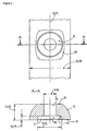
- a section of the plate, 100 is shown in a normal projection from its lower, bone-facing surface, 3, on Figure 1 , together with a transverse cross section, A-A, cut through the screw hole, 4.
- the upper surface, 2, of the plate, 100 is parallel to the lower surface, 3, while the sides of the plate, 1, may be beneficially curved and inclined, so as to make the upper surface of the plate narrower in order to facilitate closure of the soft tissue over the plate.
- the screw hole, 4, is surrounded by a recess, 5, at the lower surface, 3, of the plate. The purpose of the recess, 5, is to eliminate the potential contact of the plate and the bone surrounding the screw.
- the lower surface, 3, of the plate, 100 is essentially planar.
- the shape of the recess, 5, is shown as being circular in shape when viewed from the lower side of the plate, other shapes, such as that shown by dotted line, 8, on Figure 2 , can be used to achieve the same effect.
- a shape somewhat elongated in the direction of the long axis, 101, of the plate can be used to reduce the stresses at the transverse aspect of the plate along the remaining lower surface, 3.
- the recess can also be rounded, 6, at its base and/or faceted at its edge, 7, as one skilled in art would do to avoid stress concentrations at sharp corners, or injuries at sharp edges.
- the diameter, 103, of the recess, 5, is significantly larger than the diameter, 102, of the hole 4 and smaller than the width, 106, of the plate.
- the width of the plate should be approximately 2.5 to 3.5 times larger than the diameter of the screw hole, and the recess diameter, 103, should be about 1.5 to 2 times larger than the diameter of the screw hole, 102.
- the depth, 104, of the recess, 5, should be scaled to the thickness, 105, of the plate; a good compromise between the need to provide a safe clearance to the bone and the need to maintain sufficient strength of the plate, suggests a preferred ratio of about 1 to 4, i.e. the depth of the recess should be about 25% of the plate thickness. In general, the depth of the recess may be about 20 to about 30% of the plate thickness.
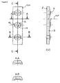
- transverse grooves, 9, formed from the lower surface, 3, and positioned between the screw holes, 4, of the plate, 100, Figure 3 .
- the depth, 107, of the grooves, 9, is about the same, or slightly larger than the depth of recesses, 5.
- Transverse cross-sections through a hole, B-B, and between two holes, A-A, are also shown on Figure 3 . Note that the apparent arch-shaped section of the lower surface is in fact just the projection of the intersecting grooves, 9, and recesses, 5.
- Preferred shape of the entry side, 11, of the screw holes, 4, is conical, Figure 4 .
- the angle of the cone, 108, should be large enough to prevent friction locking of the matching screw head, preferably about 25 degrees or more, more preferably about 30 degrees or more.
- Conical shape, 11, of the hole, 4, preferably reaches to about the mid plane of the plate - the remaining section of the hole, 4, is provided with threads, 12. These threads match the one and only thread of the locking screw.
- the exit side of the screw hole, 4 may be modified by angular release cuts, 13, Figure 5 .
- the plate disclosed here may be provided with side cuts, 14, Figure 6 , which allow for sufficient bending of the plate in both planes to match the shapes of the long bones, especially near joints.
- An important, further function of the side cuts 14, is to make the strength of the plate more uniform. This is beneficial not only for added ease of adaptation, but also for reducing the risk of plate breakage in functional use.
- FIG. 8 A construct of the plate, 100, and different screws is shown on Figure 8 .
- Preferred use of the plate, 100, for bone fracture treatment is with locking, short, screws, 20.
- conventional screws, 30, can also be used, especially if the fracture is near a joint where cortical bone is thin.
- Conventional screws have spherical heads, 31, which can be selected to just fit into the conical section 11 of the holes 4.
- the outside diameter of the conventional screw, 30, needs to be smaller than the core diameter of the locking screw, 20.
- Angular releases, 13, allow for angulation, 32, of the screw 30.
- the pilot screw hole, 33, for a conventional screw can be drilled shifted by an amount, 34, from the centre of the hole. Driving a screw down will then cause a shift of the plate and the bone.
- Screw holes, 4 can be plugged by plugs, 40, which, basically, are just short locking screws.
- plugs, 40 in the plate holes, while adapting the plate to the bone by bending and torsion, reduces the risk of excessive deformation of the hole, which could prevent proper seating of the screws, especially locking screws, 20.
- Such plugs can be pre-inserted into the holes of the plates - only those, which need to be removed in order to insert the bone screws, are removed in surgery. Keeping other plugs in the holes has a benefit of increasing the strength of the plate.
- Locking screws, 20, are shown in normal projection, a cross-section and in perspective views on Figure 9 .
- the head, 22, of the screw is matching the screw hole entry section, 11; the body, 21, of the screw is threaded with the same threads as the screw hole, 12; the conical front section, 23, is provided with thread tapping recesses, 25; the very tip of the screw, 26, is cylindrical and helps to properly centre the screw. Screws are driven via screwdriver recess 24.
Landscapes
- Health & Medical Sciences (AREA)
- Orthopedic Medicine & Surgery (AREA)
- Surgery (AREA)
- Life Sciences & Earth Sciences (AREA)
- Heart & Thoracic Surgery (AREA)
- Nuclear Medicine, Radiotherapy & Molecular Imaging (AREA)
- Engineering & Computer Science (AREA)
- Biomedical Technology (AREA)
- Neurology (AREA)
- Medical Informatics (AREA)
- Molecular Biology (AREA)
- Animal Behavior & Ethology (AREA)
- General Health & Medical Sciences (AREA)
- Public Health (AREA)
- Veterinary Medicine (AREA)
- Surgical Instruments (AREA)
- Prostheses (AREA)
Abstract
Description
- This invention relates to plates and screws for internal fixation of bone fractures. Geometry of the plate and in particular the lower, bone-facing, surface of the plate is at the core of the invention. It leads to a large reduction of the potential contact between the plate and the bone, hence minimizing the damage done to the bone vascular supply by plating itself. Furthermore, the plate screw holes are shaped to allow use of either conventional (ISO standardized) or the special, locking screws. These goals are achieved without compromising mechanical properties of the plate and the plate-bone construct.
- Healing of fractured bones treated by internal fixation depends on blood supply, which is provided to bone by both endosteal and periosteal routes. Both can be damaged in the fracture event, but also later, by the treatment. Conventional plates present a particularly high risk to the periosteal blood supply since they are made to fit the bone as closely as possible and then screwed tightly onto the bone. This kills the periosteum, and the bone, which needs it for its blood supply. Dead bone cannot heal and it presents a particularly high risk of infection. Through remodelling, bone can be restored, but seldom to its original shape and mechanical properties.
- Many different plates, which reduce the area of contact to the bone, have been introduced to clinical use during the past two decades. Related to these developments are also different solutions to stably connect, or lock, bone screws and the plates. As the contact between the plate and the bone is reduced to very small areas, locking the screws becomes imperative - conventional screws, which are anchored in bone and compress the plate to the bone could produce contact pressures in excess of bone compressive strength. This would compromise stability of the construct and hence the process of fracture healing.
-
USP 3,552,389, Allgower, et al , discloses a so-called compression plate, or dynamic compression plate, which has become de facto standard in internal fixation of bone fractures. Screws in this plate can be used to cause an axial displacement between the plate and the bone segment, resulting in compression of the bone segments at the fracture. The main drawback of these, now generic, plates is the extensive contact between the plate and the bone and consequently demolition of the periosteal blood supply. -
USP 4,484,570 , Sutter, teaches how to lock the screws in so-called mandibular, reconstruction plates. This invention has modified many of the later and current efforts to improve the plating. -
USP 4,838,252 , Klaue, discloses a bone plate of a trapezoidal shape, narrower at the side facing the bone. The intent is to reduce the contact, but stability is compromised, especially in torsion. -
USP 5,002,544 , Klaue, discloses a trapezoidal shape of the plate, combined with transverse under cuts aimed at further reducing the contact to the bone. -
USP 5,053,036, Perren, et al (The preamble of claim 1 is based on this document) teaches how to shape the lower surface of the plate using a longitudinal arch-shaped cut, and a plurality of side openings, or transverse cuts. -
USP 5,151,103, Tepic et al , discloses a solution to locking screws into the plates via friction-based, self-locking mechanism. -
USP 5,269,7841 -
USP 5,709,686, Talos, Schmoker , discloses an elongated screw hole with threads on the sidewalls, allowing for locking of the screw. -
USP 5,733,287, Tepic, Bresina , teaches how to reduce stress concentration around the screw holes. There is no teaching of recesses surrounding the screw holes on the bone-facing side of the plate. -
USP 5,741,258, Klaue, Mast , teaches another concept of a locking nut for fixing the screw to the plate. -
USP 5,810,823, Klaue, Mast , teaches how to design a plate with very small contact to the bone, centred on the screw. This, again, compromises stability, especially against torsion. -
USP 6,206,881, Frigg, Schavan , teaches how to lock the screws into a plate of lesser hardness. -
USP 6,602,255, Campbell, Harrington , teaches a locking mechanism for screws and plates with a third body (spring) element. -
US Pat. Appl. 20020045901, Wagner, Frigg , discloses an elongated screw hole designed to accept either a standard, or a locking screw. -
USP 6,017,345 discloses a bone fixation plate assembly having a number of apertures (24) wherein the bore or aperture can include at least one internal annular recess (13) on either surface. -
EP 348 390 A2 - The present invention relates to a plate for treating bone fractures according to claim 1.
- The purpose of the recess is to eliminate the potential contact of the plate and the bone surrounding the screw. The lower surface of the plate is essentially planar.
- Said recesses are preferably of approximately annular form. While the shape of the recess may be circular in shape when viewed from the lower side of the plate, other shapes can be used to achieve the same effect. A shape somewhat elongated in the direction of the long axis of the plate can be used to reduce the stresses at the transverse aspect of the plate along the remaining lower surface. The recess can also be rounded at its base and/or faceted at its edge as one skilled in art would do to avoid stress concentrations at sharp corners, or injuries at sharp edges.
- Preferably, the plate width is larger, preferably approximately 2.5 to 3.5 times larger than the diameter of said holes; and the diameter of said recesses is preferably larger, preferably approximately 1.5 to 2 times larger than the diameter of said holes.
- The depth of the recess should be scaled to the thickness of the plate; a good compromise between the need to provide a safe clearance to the bone and the need to maintain sufficient strength of the plate suggests a preferred ratio of about 1 to 4, i.e. the depth of the recess should be about 25% of the plate thickness. In general, the depth of the recess may be about 20 to about 30% of the plate thickness. In one preferred embodiment, the depth of the recesses is therefore approximately one fourth of the plate thickness.
- The plate comprises transverse grooves. The transverse grooves are positioned between at least some of the holes to further reduce the potential contact of the lower surface of the plate and the bone, leaving intact only two small areas of the original, essentially planar lower surface per said hole.
- Preferably, the transverse grooves are positioned between at least some of the holes, preferably on the lower, bone facing side of the plate. Transverse grooves may also be present on the upper side of the plate. Preferably, there is one or more transverse groove between any two holes. Transverse grooves may also be cut into the plate from the sides, or the sides may comprise side cuts which reduce the width of the plate between the holes.
- In a preferred embodiment of the present invention, the transverse groove spans the area between the recesses between two holes, and even more preferably, the transverse groove overlaps with part of the recess around the hole. This way, the plate can be designed so that the areas of the lower, bone facing side of the plate, which are not covered by transverse grooves, are very small areas. This ensures that only those small areas will contact the bone when the plate is in place. It is also possible that the transverse grooves are positioned so that they are essentially adjacent. In this case, the areas remaining for bone contact are very small or consist only of an edge. Preferably, the area remaining for bone contact has-about the width of the hole.
- The depth of the transverse grooves is preferably about the same as the depth of the recesses. Preferably, the depth of the transverse grooves is equal or larger than the depth of the recesses. Further, the depth of the transverse grooves may also be slightly larger than the depth of the recesses. Alternatively, the depth of the transverse grooves may also be slightly smaller than the depth of the recesses.
- In a preferred emodiment, the hole in its upper section adjacent to the upper surface is conical in shape. The conical section of the hole preferably has a cone angle above the self-locking range, preferably 30 degrees or more.
- The mid-to-lower section of the hole is preferably provided with threads.
- The plate of the present invention may further be provided with angular release cuts, extending longitudinal aspect of the hole in its mid-to-lower section.
- The geometry of said plate may further be modified by side cuts, spaced between at least some of the holes. In many uses of bone plates, it is desirable to bend the plate in both planes. So-called reconstruction plates with deep side cuts do exist, but those are intended for use in less loaded, complex bones, e.g. those of the pelvis. The plate disclosed in the present invention may be provided with side cuts which allow for sufficient bending of the plate in both planes to match the shapes of the long bones, especially near joints. An important, further function of the side cuts is to make the strength of the plate more uniform. This is beneficial not only for added ease of adaptation, but also for reducing the risk of plate breakage in functional use.
- The cross section between the holes preferably has lower moments of resistance than the cross section at the holes.
- The screw holes can be plugged by plugs which, basically, are just short locking screws. Using such plugs in the plate holes, while adapting the plate to the bone by bending and torsion, reduces the risk of excessive deformation of the hole, which could prevent proper seating of the screws, especially locking screws. Such plugs can be pre-inserted into the holes of the plates - only those, which need to be removed in order to insert the bone screws, are removed in surgery. Keeping other plugs in the holes has a benefit of increasing the strength of the plate. Protection of the holes during bending can be afforded by such hole plugs, which may be provided pre-installed in order to reduce surgery time. Screw hole plugs may then be left in place in the holes not used for bone screws.
- The invention further relates to a construct comprising a plate according to the invention and at least one screw-hole plug. The construct may further comprise at least one locking screw or/and the construct may further comprise at least one standard bone screw.
- The plate and the construct of the present invention are useful for the manufacture of a device for the treatment of bone fractures.
- The present invention relates in particular to a plate for treatment of bone fractures with reduced potential contact to bone through a combination of recesses of preferably approximately annular form surrounding at least some of the screw holes at the lower, bone facing surface of the plate, wherein the plate comprises transverse grooves between at least some of the holes. The plate allows for use of locking as well as conventional bone screws. With the transverse grooves cut into the plate from the lower surface and/or from the sides, the strength of the plate at the span between the holes is lower than at the screw holes. The plate can be bent in both planes without undue deformation of the screw holes. Protection of the holes during bending is afforded by hole plugs, which may be provided pre-installed in order to reduce surgery time. Screw hole plugs may then be left in place in the holes not used for bone screws.
- The plate is suitable for application in human and in veterinary medicine.
-
-
Figure 1 shows a plate segment with a screw hole and a recess from the lower surface. -
Figure 2 shows a detail of the recess. -
Figure 3 shows a plate segment with 3 holes and transverse grooves. -
Figure 4 shows a screw hole with a conical entry section from the upper surface and threads in the mid-lower section. -
Figure 5 shows a screw hole with angular release cuts from the lower surface. -
Figure 6 shows a plate with side cuts between the holes. -
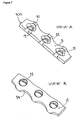
Figure 7 shows a perspective view of the plate from below and from above. -
Figure 8 shows a construct with a plate, a locking screw, a conventional screw and screw hole plug. -
Figure 9 shows a locking screw. - A section of the plate, 100, is shown in a normal projection from its lower, bone-facing surface, 3, on
Figure 1 , together with a transverse cross section, A-A, cut through the screw hole, 4. The upper surface, 2, of the plate, 100, is parallel to the lower surface, 3, while the sides of the plate, 1, may be beneficially curved and inclined, so as to make the upper surface of the plate narrower in order to facilitate closure of the soft tissue over the plate. The screw hole, 4, is surrounded by a recess, 5, at the lower surface, 3, of the plate. The purpose of the recess, 5, is to eliminate the potential contact of the plate and the bone surrounding the screw. The lower surface, 3, of the plate, 100, is essentially planar. - While the shape of the recess, 5, is shown as being circular in shape when viewed from the lower side of the plate, other shapes, such as that shown by dotted line, 8, on
Figure 2 , can be used to achieve the same effect. A shape somewhat elongated in the direction of the long axis, 101, of the plate can be used to reduce the stresses at the transverse aspect of the plate along the remaining lower surface, 3. The recess can also be rounded, 6, at its base and/or faceted at its edge, 7, as one skilled in art would do to avoid stress concentrations at sharp corners, or injuries at sharp edges. - The diameter, 103, of the recess, 5, is significantly larger than the diameter, 102, of the
hole 4 and smaller than the width, 106, of the plate. Preferably, to achieve good proportions of the screw and the plate, the width of the plate should be approximately 2.5 to 3.5 times larger than the diameter of the screw hole, and the recess diameter, 103, should be about 1.5 to 2 times larger than the diameter of the screw hole, 102. The depth, 104, of the recess, 5, should be scaled to the thickness, 105, of the plate; a good compromise between the need to provide a safe clearance to the bone and the need to maintain sufficient strength of the plate, suggests a preferred ratio of about 1 to 4, i.e. the depth of the recess should be about 25% of the plate thickness. In general, the depth of the recess may be about 20 to about 30% of the plate thickness. - A further reduction of the potential contact between the plate and the bone is achieved by transverse grooves, 9, formed from the lower surface, 3, and positioned between the screw holes, 4, of the plate, 100,
Figure 3 . The depth, 107, of the grooves, 9, is about the same, or slightly larger than the depth of recesses, 5. Transverse cross-sections through a hole, B-B, and between two holes, A-A, are also shown onFigure 3 . Note that the apparent arch-shaped section of the lower surface is in fact just the projection of the intersecting grooves, 9, and recesses, 5. - Preferred shape of the entry side, 11, of the screw holes, 4, is conical,
Figure 4 . The angle of the cone, 108, should be large enough to prevent friction locking of the matching screw head, preferably about 25 degrees or more, more preferably about 30 degrees or more. Conical shape, 11, of the hole, 4, preferably reaches to about the mid plane of the plate - the remaining section of the hole, 4, is provided with threads, 12. These threads match the one and only thread of the locking screw. - To allow for use of conventional bone screws in conjunction with this plate, and to facilitate use of these screws for lagging bone fractures (compressing bones at the fracture by a fracture surface traversing screw), should that be elected by the surgeon, the exit side of the screw hole, 4, may be modified by angular release cuts, 13,
Figure 5 . - In many uses of bone plates, it is desirable to bend the plate in both planes. So-called reconstruction plates with deep side cuts do exist, but those are intended for use in less loaded, complex bones, e.g. those of the pelvis. The plate disclosed here may be provided with side cuts, 14,
Figure 6 , which allow for sufficient bending of the plate in both planes to match the shapes of the long bones, especially near joints. An important, further function of the side cuts 14, is to make the strength of the plate more uniform. This is beneficial not only for added ease of adaptation, but also for reducing the risk of plate breakage in functional use. - All innovative features of the plate, 100, are shown again in a perspective view A, from below, and a perspective view B from above,
Figure 7 . Note that only two small areas, 10, per screw hole, 4, can potentially contact the bone the plate is placed upon. - A construct of the plate, 100, and different screws is shown on
Figure 8 . Preferred use of the plate, 100, for bone fracture treatment is with locking, short, screws, 20. However, conventional screws, 30, can also be used, especially if the fracture is near a joint where cortical bone is thin. Conventional screws have spherical heads, 31, which can be selected to just fit into theconical section 11 of theholes 4. In addition, the outside diameter of the conventional screw, 30, needs to be smaller than the core diameter of the locking screw, 20. - Angular releases, 13, allow for angulation, 32, of the
screw 30. Should self-compression of the fracture by the screw insertion be desired, the pilot screw hole, 33, for a conventional screw can be drilled shifted by an amount, 34, from the centre of the hole. Driving a screw down will then cause a shift of the plate and the bone. - Screw holes, 4, can be plugged by plugs, 40, which, basically, are just short locking screws. Using such plugs, 40, in the plate holes, while adapting the plate to the bone by bending and torsion, reduces the risk of excessive deformation of the hole, which could prevent proper seating of the screws, especially locking screws, 20. Such plugs can be pre-inserted into the holes of the plates - only those, which need to be removed in order to insert the bone screws, are removed in surgery. Keeping other plugs in the holes has a benefit of increasing the strength of the plate.
- Locking screws, 20, are shown in normal projection, a cross-section and in perspective views on
Figure 9 . The head, 22, of the screw is matching the screw hole entry section, 11; the body, 21, of the screw is threaded with the same threads as the screw hole, 12; the conical front section, 23, is provided with thread tapping recesses, 25; the very tip of the screw, 26, is cylindrical and helps to properly centre the screw. Screws are driven viascrewdriver recess 24.
Claims (18)
- A plate (100) for treating bone fractures, having an upper surface (2), a lower bone-facing surface (3), and at least two holes (4) for attachment to the bone, extending from the upper surface (2) to the lower surface (3), wherein transverse grooves (9) are positioned between at least some of the holes (4); characterized in that said holes are surrounded by recesses (5) at the lower bone-facing surface (3)
- A plate according to claim 1, wherein the transverse grooves (9) further reduce the potential contact of the lower surface (3) of the plate and the bone, leaving intact only two small areas (10) of the original lower surface (3) per said hole.
- A plate according to any one of claims 1 and 2, wherein the transverse grooves (9) span the area between the recesses (5) at the lower surface (3).
- A plate according to any one of claims 1 to 3, wherein the transverse grooves (9) at least partially overlap with a portion of the recesses (5) at the lower surface (3).
- A plate according to any one of the preceding claims, wherein the depth of the transverse grooves is equal or larger than the depth of the recesses (5).
- A plate according to any one of the preceding claims, wherein said recesses are of approximately annular form.
- A plate according to any one of the preceding claims, wherein the plate width (106) is approximately 2.5 to 3.5 times larger than the diameter (102) of said holes (4); and the diameter (103) of said recesses is approximately 1.5 to 2 times larger than the diameter (102) of said holes (4).
- A plate according to any preceding claims, wherein the depth (104) of the recesses (5) is approximately one fourth of the plate thickness (105).
- A plate according to one of the preceding claims, wherein the hole (4) in its upper section (11) adjacent to the upper surface (2) is conical in shape.
- A plate according to claim 9, wherein the conical section (11) of the hole (4) has a cone angle (108) above the self-locking range, preferably 30 degrees or more.
- A plate according to one of the claims 9 or 10, wherein the mid-to-lower section (12) of the hole (4) is provided with threads.
- A plate according to one of the preceding claims, further provided with angular release cuts (13) extending longitudinal aspect of the hole (4) in its mid-to-lower section.
- A plate according to one of the preceding claims, wherein the geometry of said plate is further modified by side cuts (14) spaced between at least some of the holes (4).
- A plate according to claim 13, wherein the cross section between the holes has lower moments of resistance than the cross section at the holes.
- A construct comprising a plate according to any one of the preceding claims and at least one screw-hole plug (40).
- A construct comprising a plate according to any one of the preceding claims 1 to 14 or a construct according to claim 15 and at least one locking screw (20).
- A construct comprising a plate according to any one of the preceding claims 1 to 14 or a construct according to claims 15 or 16 and at least one standard bone screw (30).
- The use of a plate of any one of the preceding claims 1 to 14 or a construct of any one of claims 15 to 17 for the manufacture of a device for the treatment of bone fractures.
Priority Applications (1)
| Application Number | Priority Date | Filing Date | Title |
|---|---|---|---|
| EP06707058A EP1865866B1 (en) | 2005-02-22 | 2006-02-17 | Plate and screws for treatment of bone fractures |
Applications Claiming Priority (3)
| Application Number | Priority Date | Filing Date | Title |
|---|---|---|---|
| EP05003773A EP1693013A1 (en) | 2005-02-22 | 2005-02-22 | Plate and screws for treatment of bone fractures |
| EP06707058A EP1865866B1 (en) | 2005-02-22 | 2006-02-17 | Plate and screws for treatment of bone fractures |
| PCT/EP2006/001473 WO2006089695A1 (en) | 2005-02-22 | 2006-02-17 | Plate and screws for treatment of bone fractures |
Publications (2)
| Publication Number | Publication Date |
|---|---|
| EP1865866A1 EP1865866A1 (en) | 2007-12-19 |
| EP1865866B1 true EP1865866B1 (en) | 2011-09-14 |
Family
ID=35058827
Family Applications (2)
| Application Number | Title | Priority Date | Filing Date |
|---|---|---|---|
| EP05003773A Withdrawn EP1693013A1 (en) | 2005-02-22 | 2005-02-22 | Plate and screws for treatment of bone fractures |
| EP06707058A Expired - Lifetime EP1865866B1 (en) | 2005-02-22 | 2006-02-17 | Plate and screws for treatment of bone fractures |
Family Applications Before (1)
| Application Number | Title | Priority Date | Filing Date |
|---|---|---|---|
| EP05003773A Withdrawn EP1693013A1 (en) | 2005-02-22 | 2005-02-22 | Plate and screws for treatment of bone fractures |
Country Status (6)
| Country | Link |
|---|---|
| US (1) | US8968368B2 (en) |
| EP (2) | EP1693013A1 (en) |
| JP (1) | JP4971195B2 (en) |
| AT (1) | ATE524125T1 (en) |
| ES (1) | ES2369280T3 (en) |
| WO (1) | WO2006089695A1 (en) |
Families Citing this family (87)
| Publication number | Priority date | Publication date | Assignee | Title |
|---|---|---|---|---|
| WO2008007194A2 (en) * | 2006-07-07 | 2008-01-17 | Precimed, S.A. | Bone plate with complex, adjacent holes joined by a bend relief zone |
| FR2922094B1 (en) * | 2007-10-11 | 2010-09-17 | Small Bone Innovations Interna | PART FOR FIXING ON ONE OR MORE BONDS OR ON BONE PARTS TO BE REUNIRED, AND ARTHRODESIS OR OSTEOSYNTHESIS EQUIPMENT COMPRISING SUCH PART AND AT LEAST ONE SCREW |
| EP2397089B1 (en) * | 2007-11-02 | 2014-08-13 | Biomet C.V. | Elbow fracture fixation system |
| US8808333B2 (en) | 2009-07-06 | 2014-08-19 | Zimmer Gmbh | Periprosthetic bone plates |
| US8834532B2 (en) * | 2009-07-07 | 2014-09-16 | Zimmer Gmbh | Plate for the treatment of bone fractures |
| USD642686S1 (en) | 2009-07-07 | 2011-08-02 | Zimmer Gmbh | Orthopaedic bone plate |
| US8808335B2 (en) | 2010-03-08 | 2014-08-19 | Miami Device Solutions, Llc | Locking element for a polyaxial bone anchor, bone plate assembly and tool |
| US8790379B2 (en) | 2010-06-23 | 2014-07-29 | Zimmer, Inc. | Flexible plate fixation of bone fractures |
| AU2011270934B2 (en) | 2010-06-23 | 2014-09-11 | Zimmer, Inc | Flexible plate fixation of bone fractures |
| KR101856459B1 (en) | 2010-08-31 | 2018-05-10 | 신세스 게엠바하 | Controlling the degradation of bioresorbable metal implants |
| US8551095B2 (en) * | 2011-02-02 | 2013-10-08 | Bionet Manufacturing, LLC | Bone plate having combination locking and compression screw holes |
| US9427269B2 (en) | 2011-03-14 | 2016-08-30 | Genossis Llc | Locking screws and plates |
| JP2014522673A (en) | 2011-06-15 | 2014-09-08 | スミス アンド ネフュー インコーポレーテッド | Locking implant with variable angle |
| JP6046714B2 (en) | 2011-07-18 | 2016-12-21 | ウッドウェルディング・アクチェンゲゼルシャフト | Method and implant for stabilizing separated bone parts relative to one another |
| US10039582B2 (en) * | 2011-12-20 | 2018-08-07 | DePuy Synthes Products, Inc. | Self centering feature for an intramedullary nail |
| US9295508B2 (en) | 2012-02-03 | 2016-03-29 | Zimmer, Inc. | Bone plate for elastic osteosynthesis |
| WO2014031851A1 (en) | 2012-08-22 | 2014-02-27 | Amphenol Corporation | High-frequency electrical connector |
| WO2015095126A1 (en) | 2013-12-20 | 2015-06-25 | Hartdegen Vernon | Polyaxial locking hole |
| JP2017529886A (en) | 2014-07-10 | 2017-10-12 | クロスローズ エクストリミティ システムズ リミテッド ライアビリティ カンパニー | Bone implant and means of insertion |
| US11202626B2 (en) | 2014-07-10 | 2021-12-21 | Crossroads Extremity Systems, Llc | Bone implant with means for multi directional force and means of insertion |
| PL231693B1 (en) * | 2014-09-12 | 2019-03-29 | Chm Spolka Z Ograniczona Odpowiedzialnoscia | Bone plate complex with the bone screw for stabilization of fractures |
| CN107112696B (en) | 2014-11-12 | 2020-06-09 | 安费诺有限公司 | Very high speed, high density electrical interconnect system with impedance control in the mating area |
| JP6401853B2 (en) | 2015-02-20 | 2018-10-10 | オリンパス株式会社 | Therapeutic energy application structure and medical treatment apparatus |
| JP6600010B2 (en) * | 2015-04-24 | 2019-10-30 | バイオメット マニュファクチャリング,リミティド ライアビリティ カンパニー | Clavicle implant |
| JP6560434B2 (en) | 2015-07-13 | 2019-08-14 | クロスローズ エクストリミティ システムズ リミテッド ライアビリティ カンパニー | Bone plate with dynamic elements |
| US10687874B2 (en) | 2015-08-27 | 2020-06-23 | Globus Medical, Inc | Proximal humeral stabilization system |
| US11076898B2 (en) | 2015-08-27 | 2021-08-03 | Globus Medical, Inc. | Proximal humeral stabilization system |
| US11197682B2 (en) | 2015-08-27 | 2021-12-14 | Globus Medical, Inc. | Proximal humeral stabilization system |
| WO2017048909A1 (en) | 2015-09-18 | 2017-03-23 | Smith & Nephew, Inc. | Bone plate |
| US10130402B2 (en) | 2015-09-25 | 2018-11-20 | Globus Medical, Inc. | Bone fixation devices having a locking feature |
| US9974581B2 (en) | 2015-11-20 | 2018-05-22 | Globus Medical, Inc. | Expandable intramedullary systems and methods of using the same |
| US9795411B2 (en) | 2016-03-02 | 2017-10-24 | Globus Medical, Inc. | Fixators for bone stabilization and associated systems and methods |
| US10531905B2 (en) | 2016-04-19 | 2020-01-14 | Globus Medical, Inc. | Implantable compression screws |
| CN109565137A (en) | 2016-05-31 | 2019-04-02 | 安费诺有限公司 | High-performance cable termination device |
| EP3257458A1 (en) * | 2016-06-17 | 2017-12-20 | ORTHOFIX S.r.l. | Bone plate for epiphysiodesis |
| US10687873B2 (en) | 2016-08-17 | 2020-06-23 | Globus Medical Inc. | Stabilization systems |
| US11213327B2 (en) | 2016-08-17 | 2022-01-04 | Globus Medical, Inc. | Fracture plates, systems, and methods |
| US11141204B2 (en) | 2016-08-17 | 2021-10-12 | Globus Medical Inc. | Wrist stabilization systems |
| US11197701B2 (en) | 2016-08-17 | 2021-12-14 | Globus Medical, Inc. | Stabilization systems |
| US12588937B2 (en) | 2016-08-17 | 2026-03-31 | Globus Medical, Inc. | Volar distal radius stabilization system |
| US11432857B2 (en) | 2016-08-17 | 2022-09-06 | Globus Medical, Inc. | Stabilization systems |
| US10383668B2 (en) | 2016-08-17 | 2019-08-20 | Globus Medical, Inc. | Volar distal radius stabilization system |
| US10575884B2 (en) | 2016-08-17 | 2020-03-03 | Globus Medical, Inc. | Fracture plates, systems, and methods |
| US10420596B2 (en) | 2016-08-17 | 2019-09-24 | Globus Medical, Inc. | Volar distal radius stabilization system |
| US10751098B2 (en) | 2016-08-17 | 2020-08-25 | Globus Medical Inc. | Stabilization systems |
| US11331128B2 (en) | 2016-08-17 | 2022-05-17 | Globus Medical Inc. | Distal radius stabilization system |
| US10299847B2 (en) | 2016-09-22 | 2019-05-28 | Globus Medical, Inc. | Systems and methods for intramedullary nail implantation |
| CN115189188A (en) | 2016-10-19 | 2022-10-14 | 安费诺有限公司 | Flexible shielding piece, electric connector and electronic device |
| US11864753B2 (en) | 2017-02-06 | 2024-01-09 | Crossroads Extremity Systems, Llc | Implant inserter |
| EP3579762B1 (en) | 2017-02-07 | 2024-06-26 | Crossroads Extremity Systems, LLC | Counter-torque implant |
| US10881438B2 (en) | 2017-03-10 | 2021-01-05 | Globus Medical, Inc. | Clavicle fixation system |
| US10905477B2 (en) | 2017-03-13 | 2021-02-02 | Globus Medical, Inc. | Bone stabilization systems |
| US10368928B2 (en) | 2017-03-13 | 2019-08-06 | Globus Medical, Inc. | Bone stabilization systems |
| USD870284S1 (en) | 2017-07-31 | 2019-12-17 | Crossroads Extremity Systems, Llc | Osteosynthesis clip |
| CN119209123A (en) | 2017-08-03 | 2024-12-27 | 安费诺有限公司 | Cable connectors for high-speed interconnects |
| US10856920B2 (en) | 2017-09-13 | 2020-12-08 | Globus Medical Inc. | Bone stabilization systems |
| US11096730B2 (en) | 2017-09-13 | 2021-08-24 | Globus Medical Inc. | Bone stabilization systems |
| US12279795B2 (en) | 2017-09-13 | 2025-04-22 | Globus Medical, Inc. | Bone stabilization systems |
| US11071570B2 (en) * | 2018-03-02 | 2021-07-27 | Globus Medical, Inc. | Distal tibial plating system |
| US11224468B2 (en) | 2018-03-02 | 2022-01-18 | Globus Medical, Inc. | Distal tibial plating system |
| US10665973B2 (en) | 2018-03-22 | 2020-05-26 | Amphenol Corporation | High density electrical connector |
| WO2019195319A1 (en) | 2018-04-02 | 2019-10-10 | Ardent Concepts, Inc. | Controlled-impedance compliant cable termination |
| US11141172B2 (en) | 2018-04-11 | 2021-10-12 | Globus Medical, Inc. | Method and apparatus for locking a drill guide in a polyaxial hole |
| US10931062B2 (en) | 2018-11-21 | 2021-02-23 | Amphenol Corporation | High-frequency electrical connector |
| WO2020154526A1 (en) | 2019-01-25 | 2020-07-30 | Fci Usa Llc | I/o connector configured for cabled connection to the midboard |
| CN117175239A (en) | 2019-01-25 | 2023-12-05 | 富加宜(美国)有限责任公司 | Socket connectors and electrical connectors |
| US11202663B2 (en) | 2019-02-13 | 2021-12-21 | Globus Medical, Inc. | Proximal humeral stabilization systems and methods thereof |
| CN113728521B (en) | 2019-02-22 | 2025-03-18 | 安费诺有限公司 | High-performance cable connector assemblies |
| EP3795104A1 (en) | 2019-09-18 | 2021-03-24 | Kyon AG | Bead head for locking bone screws |
| CN114788097A (en) | 2019-09-19 | 2022-07-22 | 安费诺有限公司 | High speed electronic system with midplane cable connector |
| US10743922B1 (en) | 2019-09-27 | 2020-08-18 | Trilliant Surgical Llc | Variable angle locking construct for orthopedic applications |
| US12185995B2 (en) | 2019-10-09 | 2025-01-07 | Globus Medical, Inc. | Bone stabilization systems |
| US11129627B2 (en) | 2019-10-30 | 2021-09-28 | Globus Medical, Inc. | Method and apparatus for inserting a bone plate |
| US11324538B2 (en) | 2019-12-04 | 2022-05-10 | Biomet Manufacturing, Llc | Active bone plate |
| US11723647B2 (en) | 2019-12-17 | 2023-08-15 | Globus Medical, Inc. | Syndesmosis fixation assembly |
| CN115428275B (en) | 2020-01-27 | 2025-12-30 | 富加宜(美国)有限责任公司 | High-speed connector |
| WO2021154718A1 (en) | 2020-01-27 | 2021-08-05 | Fci Usa Llc | High speed, high density direct mate orthogonal connector |
| CN113258325A (en) | 2020-01-28 | 2021-08-13 | 富加宜(美国)有限责任公司 | High-frequency middle plate connector |
| US12059183B2 (en) | 2020-07-31 | 2024-08-13 | Crossroads Extremity Systems, Llc | Bone plates with dynamic elements and screws |
| USD949341S1 (en) | 2020-09-29 | 2022-04-19 | Trilliant Surgical Llc | Bone fixation plate |
| JP7693984B2 (en) * | 2020-10-30 | 2025-06-18 | デピュイ・シンセス・プロダクツ・インコーポレイテッド | Bone plate with multiple use screw holes for locking and compression screws - Patents.com |
| USD961081S1 (en) | 2020-11-18 | 2022-08-16 | Crossroads Extremity Systems, Llc | Orthopedic implant |
| EP4262597A2 (en) * | 2020-12-17 | 2023-10-25 | DGT Medical Limited | A bone fixation device and system |
| USD1002553S1 (en) | 2021-11-03 | 2023-10-24 | Amphenol Corporation | Gasket for connector |
| US12064150B2 (en) | 2022-01-19 | 2024-08-20 | Globus Medical Inc. | System and method for treating bone fractures |
| US12478365B2 (en) | 2022-08-24 | 2025-11-25 | Globus Medical, Inc. | Systems, devices and methods for implanting suture buttons |
| US12678207B2 (en) | 2023-11-02 | 2026-07-14 | Globus Medical Inc. | Fracture plating systems |
Family Cites Families (33)
| Publication number | Priority date | Publication date | Assignee | Title |
|---|---|---|---|---|
| CH462375A (en) | 1966-06-22 | 1968-09-15 | Synthes Ag | Osteosynthetic pressure plate |
| FR1538053A (en) * | 1967-08-18 | 1968-09-07 | Osteosynthesis plate combined with its key | |
| US3695259A (en) * | 1970-11-10 | 1972-10-03 | Clyde E Yost | Bone plate |
| CH613858A5 (en) * | 1977-04-22 | 1979-10-31 | Straumann Inst Ag | |
| CH648197A5 (en) | 1980-05-28 | 1985-03-15 | Synthes Ag | IMPLANT AND SCREW FASTENING ON ITS BONE. |
| US4696290A (en) * | 1983-12-16 | 1987-09-29 | Acromed Corporation | Apparatus for straightening spinal columns |
| CH668174A5 (en) | 1985-08-30 | 1988-12-15 | Synthes Ag | OSTEOSYNTHETIC PRINT PLATE. |
| EP0340223A1 (en) | 1987-11-03 | 1989-11-08 | Synthes AG, Chur | Implant for osteosynthesis |
| US5151103A (en) | 1987-11-03 | 1992-09-29 | Synthes (U.S.A.) | Point contact bone compression plate |
| CH673762A5 (en) | 1987-12-02 | 1990-04-12 | Synthes Ag | |
| US5474553A (en) * | 1989-04-18 | 1995-12-12 | Rainer Baumgart | System for setting tubular bone fractures |
| JPH0810181Y2 (en) * | 1990-01-31 | 1996-03-27 | 太陽誘電株式会社 | Electronic parts holder for edge coating |
| DE4119447C1 (en) * | 1991-06-13 | 1992-10-15 | Aesculap Ag, 7200 Tuttlingen, De | osteosynthesis implant |
| CH686339A5 (en) * | 1991-12-10 | 1996-03-15 | Synthes Ag | Nut for the plate fixation. |
| CA2109907C (en) * | 1992-11-25 | 2000-01-25 | Ronald A. Yapp | Osteosynthesis plate system |
| CA2144353C (en) | 1994-05-24 | 2001-08-21 | Slobodan Tepic | Bone plate |
| DE19511268A1 (en) * | 1995-03-27 | 1996-10-02 | Johannes Franz Dr Med Hoenig | Osteosynthesis plate for bone stabilising e.g. post-tumour resection etc. |
| JP3542133B2 (en) | 1995-03-27 | 2004-07-14 | ジンテーズ アクチエンゲゼルシャフト,クール | Bone plate |
| EP0917450A1 (en) * | 1996-08-12 | 1999-05-26 | SYNTHES AG Chur | Bone plate |
| US6017345A (en) * | 1997-05-09 | 2000-01-25 | Spinal Innovations, L.L.C. | Spinal fixation plate |
| US6123709A (en) * | 1997-07-25 | 2000-09-26 | Jones; Andrew R. | Bone buttress plate and method of using same |
| GB9801986D0 (en) * | 1998-01-31 | 1998-03-25 | Depuy Int Ltd | A fixation device for a bone fracture |
| US6093201A (en) * | 1999-01-19 | 2000-07-25 | Ethicon, Inc. | Biocompatible absorbable polymer plating system for tissue fixation |
| US6129730A (en) * | 1999-02-10 | 2000-10-10 | Depuy Acromed, Inc. | Bi-fed offset pitch bone screw |
| MXPA02012300A (en) * | 2000-06-26 | 2003-04-25 | Synthes Ag | Bone plate for osteosynthesis. |
| US7537604B2 (en) * | 2002-11-19 | 2009-05-26 | Acumed Llc | Bone plates with slots |
| US20030187443A1 (en) * | 2002-03-27 | 2003-10-02 | Carl Lauryssen | Anterior bone plate system and method of use |
| US7862597B2 (en) * | 2002-08-22 | 2011-01-04 | Warsaw Orthopedic, Inc. | System for stabilizing a portion of the spine |
| US20040097937A1 (en) * | 2002-11-19 | 2004-05-20 | Sandi Pike | Orthopedic bone plate |
| US7608096B2 (en) * | 2003-03-10 | 2009-10-27 | Warsaw Orthopedic, Inc. | Posterior pedicle screw and plate system and methods |
| WO2004084701A2 (en) * | 2003-03-26 | 2004-10-07 | Swiss Orthopedic Solutions Sa | Locking bone plate |
| JP3099430U (en) | 2003-07-24 | 2004-04-08 | 維綱生物科技股▲ふん▼有限公司 | Medical bone plate |
| US8246664B2 (en) * | 2009-02-24 | 2012-08-21 | Osteomed Llc | Multiple bone fusion plate |
-
2005
- 2005-02-22 EP EP05003773A patent/EP1693013A1/en not_active Withdrawn
-
2006
- 2006-02-17 WO PCT/EP2006/001473 patent/WO2006089695A1/en not_active Ceased
- 2006-02-17 US US11/816,668 patent/US8968368B2/en active Active
- 2006-02-17 ES ES06707058T patent/ES2369280T3/en not_active Expired - Lifetime
- 2006-02-17 AT AT06707058T patent/ATE524125T1/en not_active IP Right Cessation
- 2006-02-17 EP EP06707058A patent/EP1865866B1/en not_active Expired - Lifetime
- 2006-02-17 JP JP2007555536A patent/JP4971195B2/en not_active Expired - Lifetime
Also Published As
| Publication number | Publication date |
|---|---|
| ATE524125T1 (en) | 2011-09-15 |
| WO2006089695A1 (en) | 2006-08-31 |
| JP2008531078A (en) | 2008-08-14 |
| JP4971195B2 (en) | 2012-07-11 |
| EP1693013A1 (en) | 2006-08-23 |
| EP1865866A1 (en) | 2007-12-19 |
| ES2369280T3 (en) | 2011-11-29 |
| US8968368B2 (en) | 2015-03-03 |
| US20080200955A1 (en) | 2008-08-21 |
Similar Documents
| Publication | Publication Date | Title |
|---|---|---|
| US8968368B2 (en) | Plate and screws for treatment of bone fractures | |
| US10463409B2 (en) | Modular fracture fixation system | |
| US7695502B2 (en) | Bone stabilization system including plate having fixed-angle holes together with unidirectional locking screws and surgeon-directed locking screws | |
| EP1861032B1 (en) | Modular fracture fixation plate system | |
| CN101883532B (en) | Distal tibia plating system | |
| US7905909B2 (en) | Bone stabilization system including multi-directional threaded fixation element | |
| US6730091B1 (en) | Blockable bone plate | |
| KR101524518B1 (en) | Bone plates and bone plate assemblies | |
| KR101104660B1 (en) | Locking bone plate | |
| WO2001056452A2 (en) | Volar fixation system |
Legal Events
| Date | Code | Title | Description |
|---|---|---|---|
| PUAI | Public reference made under article 153(3) epc to a published international application that has entered the european phase |
Free format text: ORIGINAL CODE: 0009012 |
|
| 17P | Request for examination filed |
Effective date: 20070816 |
|
| AK | Designated contracting states |
Kind code of ref document: A1 Designated state(s): AT BE BG CH CY CZ DE DK EE ES FI FR GB GR HU IE IS IT LI LT LU LV MC NL PL PT RO SE SI SK TR |
|
| DAX | Request for extension of the european patent (deleted) | ||
| GRAP | Despatch of communication of intention to grant a patent |
Free format text: ORIGINAL CODE: EPIDOSNIGR1 |
|
| GRAS | Grant fee paid |
Free format text: ORIGINAL CODE: EPIDOSNIGR3 |
|
| GRAA | (expected) grant |
Free format text: ORIGINAL CODE: 0009210 |
|
| AK | Designated contracting states |
Kind code of ref document: B1 Designated state(s): AT BE BG CH CY CZ DE DK EE ES FI FR GB GR HU IE IS IT LI LT LU LV MC NL PL PT RO SE SI SK TR |
|
| REG | Reference to a national code |
Ref country code: GB Ref legal event code: FG4D |
|
| REG | Reference to a national code |
Ref country code: CH Ref legal event code: EP Ref country code: CH Ref legal event code: NV Representative=s name: BOHEST AG |
|
| REG | Reference to a national code |
Ref country code: IE Ref legal event code: FG4D |
|
| REG | Reference to a national code |
Ref country code: ES Ref legal event code: FG2A Ref document number: 2369280 Country of ref document: ES Kind code of ref document: T3 Effective date: 20111129 |
|
| REG | Reference to a national code |
Ref country code: DE Ref legal event code: R096 Ref document number: 602006024367 Country of ref document: DE Effective date: 20111201 |
|
| REG | Reference to a national code |
Ref country code: NL Ref legal event code: VDEP Effective date: 20110914 |
|
| PG25 | Lapsed in a contracting state [announced via postgrant information from national office to epo] |
Ref country code: SE Free format text: LAPSE BECAUSE OF FAILURE TO SUBMIT A TRANSLATION OF THE DESCRIPTION OR TO PAY THE FEE WITHIN THE PRESCRIBED TIME-LIMIT Effective date: 20110914 Ref country code: FI Free format text: LAPSE BECAUSE OF FAILURE TO SUBMIT A TRANSLATION OF THE DESCRIPTION OR TO PAY THE FEE WITHIN THE PRESCRIBED TIME-LIMIT Effective date: 20110914 Ref country code: LT Free format text: LAPSE BECAUSE OF FAILURE TO SUBMIT A TRANSLATION OF THE DESCRIPTION OR TO PAY THE FEE WITHIN THE PRESCRIBED TIME-LIMIT Effective date: 20110914 |
|
| LTIE | Lt: invalidation of european patent or patent extension |
Effective date: 20110914 |
|
| PG25 | Lapsed in a contracting state [announced via postgrant information from national office to epo] |
Ref country code: CY Free format text: LAPSE BECAUSE OF FAILURE TO SUBMIT A TRANSLATION OF THE DESCRIPTION OR TO PAY THE FEE WITHIN THE PRESCRIBED TIME-LIMIT Effective date: 20110914 Ref country code: LV Free format text: LAPSE BECAUSE OF FAILURE TO SUBMIT A TRANSLATION OF THE DESCRIPTION OR TO PAY THE FEE WITHIN THE PRESCRIBED TIME-LIMIT Effective date: 20110914 Ref country code: GR Free format text: LAPSE BECAUSE OF FAILURE TO SUBMIT A TRANSLATION OF THE DESCRIPTION OR TO PAY THE FEE WITHIN THE PRESCRIBED TIME-LIMIT Effective date: 20111215 Ref country code: SI Free format text: LAPSE BECAUSE OF FAILURE TO SUBMIT A TRANSLATION OF THE DESCRIPTION OR TO PAY THE FEE WITHIN THE PRESCRIBED TIME-LIMIT Effective date: 20110914 Ref country code: AT Free format text: LAPSE BECAUSE OF FAILURE TO SUBMIT A TRANSLATION OF THE DESCRIPTION OR TO PAY THE FEE WITHIN THE PRESCRIBED TIME-LIMIT Effective date: 20110914 |
|
| REG | Reference to a national code |
Ref country code: AT Ref legal event code: MK05 Ref document number: 524125 Country of ref document: AT Kind code of ref document: T Effective date: 20110914 |
|
| PG25 | Lapsed in a contracting state [announced via postgrant information from national office to epo] |
Ref country code: BE Free format text: LAPSE BECAUSE OF FAILURE TO SUBMIT A TRANSLATION OF THE DESCRIPTION OR TO PAY THE FEE WITHIN THE PRESCRIBED TIME-LIMIT Effective date: 20110914 |
|
| PG25 | Lapsed in a contracting state [announced via postgrant information from national office to epo] |
Ref country code: CZ Free format text: LAPSE BECAUSE OF FAILURE TO SUBMIT A TRANSLATION OF THE DESCRIPTION OR TO PAY THE FEE WITHIN THE PRESCRIBED TIME-LIMIT Effective date: 20110914 Ref country code: IS Free format text: LAPSE BECAUSE OF FAILURE TO SUBMIT A TRANSLATION OF THE DESCRIPTION OR TO PAY THE FEE WITHIN THE PRESCRIBED TIME-LIMIT Effective date: 20120114 Ref country code: SK Free format text: LAPSE BECAUSE OF FAILURE TO SUBMIT A TRANSLATION OF THE DESCRIPTION OR TO PAY THE FEE WITHIN THE PRESCRIBED TIME-LIMIT Effective date: 20110914 |
|
| PG25 | Lapsed in a contracting state [announced via postgrant information from national office to epo] |
Ref country code: RO Free format text: LAPSE BECAUSE OF FAILURE TO SUBMIT A TRANSLATION OF THE DESCRIPTION OR TO PAY THE FEE WITHIN THE PRESCRIBED TIME-LIMIT Effective date: 20110914 Ref country code: PL Free format text: LAPSE BECAUSE OF FAILURE TO SUBMIT A TRANSLATION OF THE DESCRIPTION OR TO PAY THE FEE WITHIN THE PRESCRIBED TIME-LIMIT Effective date: 20110914 Ref country code: NL Free format text: LAPSE BECAUSE OF FAILURE TO SUBMIT A TRANSLATION OF THE DESCRIPTION OR TO PAY THE FEE WITHIN THE PRESCRIBED TIME-LIMIT Effective date: 20110914 Ref country code: PT Free format text: LAPSE BECAUSE OF FAILURE TO SUBMIT A TRANSLATION OF THE DESCRIPTION OR TO PAY THE FEE WITHIN THE PRESCRIBED TIME-LIMIT Effective date: 20120116 Ref country code: EE Free format text: LAPSE BECAUSE OF FAILURE TO SUBMIT A TRANSLATION OF THE DESCRIPTION OR TO PAY THE FEE WITHIN THE PRESCRIBED TIME-LIMIT Effective date: 20110914 |
|
| PLBE | No opposition filed within time limit |
Free format text: ORIGINAL CODE: 0009261 |
|
| STAA | Information on the status of an ep patent application or granted ep patent |
Free format text: STATUS: NO OPPOSITION FILED WITHIN TIME LIMIT |
|
| PG25 | Lapsed in a contracting state [announced via postgrant information from national office to epo] |
Ref country code: DK Free format text: LAPSE BECAUSE OF FAILURE TO SUBMIT A TRANSLATION OF THE DESCRIPTION OR TO PAY THE FEE WITHIN THE PRESCRIBED TIME-LIMIT Effective date: 20110914 |
|
| 26N | No opposition filed |
Effective date: 20120615 |
|
| PG25 | Lapsed in a contracting state [announced via postgrant information from national office to epo] |
Ref country code: MC Free format text: LAPSE BECAUSE OF NON-PAYMENT OF DUE FEES Effective date: 20120229 |
|
| REG | Reference to a national code |
Ref country code: DE Ref legal event code: R097 Ref document number: 602006024367 Country of ref document: DE Effective date: 20120615 |
|
| REG | Reference to a national code |
Ref country code: IE Ref legal event code: MM4A |
|
| PG25 | Lapsed in a contracting state [announced via postgrant information from national office to epo] |
Ref country code: IE Free format text: LAPSE BECAUSE OF NON-PAYMENT OF DUE FEES Effective date: 20120217 |
|
| PG25 | Lapsed in a contracting state [announced via postgrant information from national office to epo] |
Ref country code: BG Free format text: LAPSE BECAUSE OF FAILURE TO SUBMIT A TRANSLATION OF THE DESCRIPTION OR TO PAY THE FEE WITHIN THE PRESCRIBED TIME-LIMIT Effective date: 20111214 |
|
| PG25 | Lapsed in a contracting state [announced via postgrant information from national office to epo] |
Ref country code: TR Free format text: LAPSE BECAUSE OF FAILURE TO SUBMIT A TRANSLATION OF THE DESCRIPTION OR TO PAY THE FEE WITHIN THE PRESCRIBED TIME-LIMIT Effective date: 20110914 |
|
| PG25 | Lapsed in a contracting state [announced via postgrant information from national office to epo] |
Ref country code: LU Free format text: LAPSE BECAUSE OF NON-PAYMENT OF DUE FEES Effective date: 20120217 |
|
| REG | Reference to a national code |
Ref country code: CH Ref legal event code: PCAR Free format text: NEW ADDRESS: HOLBEINSTRASSE 36-38, 4051 BASEL (CH) |
|
| PG25 | Lapsed in a contracting state [announced via postgrant information from national office to epo] |
Ref country code: HU Free format text: LAPSE BECAUSE OF FAILURE TO SUBMIT A TRANSLATION OF THE DESCRIPTION OR TO PAY THE FEE WITHIN THE PRESCRIBED TIME-LIMIT Effective date: 20060217 |
|
| REG | Reference to a national code |
Ref country code: FR Ref legal event code: PLFP Year of fee payment: 10 |
|
| REG | Reference to a national code |
Ref country code: FR Ref legal event code: PLFP Year of fee payment: 11 |
|
| REG | Reference to a national code |
Ref country code: FR Ref legal event code: PLFP Year of fee payment: 12 |
|
| REG | Reference to a national code |
Ref country code: FR Ref legal event code: PLFP Year of fee payment: 13 |
|
| PGFP | Annual fee paid to national office [announced via postgrant information from national office to epo] |
Ref country code: DE Payment date: 20250129 Year of fee payment: 20 |
|
| PGFP | Annual fee paid to national office [announced via postgrant information from national office to epo] |
Ref country code: ES Payment date: 20250328 Year of fee payment: 20 |
|
| PGFP | Annual fee paid to national office [announced via postgrant information from national office to epo] |
Ref country code: CH Payment date: 20250301 Year of fee payment: 20 |
|
| PGFP | Annual fee paid to national office [announced via postgrant information from national office to epo] |
Ref country code: FR Payment date: 20250221 Year of fee payment: 20 |
|
| PGFP | Annual fee paid to national office [announced via postgrant information from national office to epo] |
Ref country code: IT Payment date: 20250224 Year of fee payment: 20 Ref country code: GB Payment date: 20250219 Year of fee payment: 20 |
|
| REG | Reference to a national code |
Ref country code: CH Ref legal event code: H14 Free format text: ST27 STATUS EVENT CODE: U-0-0-H10-H14 (AS PROVIDED BY THE NATIONAL OFFICE) Effective date: 20260217 Ref country code: DE Ref legal event code: R071 Ref document number: 602006024367 Country of ref document: DE |
|
| REG | Reference to a national code |
Ref country code: ES Ref legal event code: FD2A Effective date: 20260227 |
|
| REG | Reference to a national code |
Ref country code: GB Ref legal event code: PE20 Expiry date: 20260216 |
|
| PG25 | Lapsed in a contracting state [announced via postgrant information from national office to epo] |
Ref country code: ES Free format text: LAPSE BECAUSE OF EXPIRATION OF PROTECTION Effective date: 20260218 |