EP1865690A1 - Portable terminal - Google Patents
Portable terminal Download PDFInfo
- Publication number
- EP1865690A1 EP1865690A1 EP06730268A EP06730268A EP1865690A1 EP 1865690 A1 EP1865690 A1 EP 1865690A1 EP 06730268 A EP06730268 A EP 06730268A EP 06730268 A EP06730268 A EP 06730268A EP 1865690 A1 EP1865690 A1 EP 1865690A1
- Authority
- EP
- European Patent Office
- Prior art keywords
- sound
- emission portion
- sound emission
- receiving speaker
- housing
- Prior art date
- Legal status (The legal status is an assumption and is not a legal conclusion. Google has not performed a legal analysis and makes no representation as to the accuracy of the status listed.)
- Granted
Links
Images


Classifications
-
- H—ELECTRICITY
- H04—ELECTRIC COMMUNICATION TECHNIQUE
- H04R—LOUDSPEAKERS, MICROPHONES, GRAMOPHONE PICK-UPS OR LIKE ACOUSTIC ELECTROMECHANICAL TRANSDUCERS; ELECTRIC HEARING AIDS; PUBLIC ADDRESS SYSTEMS
- H04R1/00—Details of transducers, loudspeakers or microphones
- H04R1/02—Casings; Cabinets ; Supports therefor; Mountings therein
- H04R1/021—Casings; Cabinets ; Supports therefor; Mountings therein incorporating only one transducer
-
- H—ELECTRICITY
- H04—ELECTRIC COMMUNICATION TECHNIQUE
- H04M—TELEPHONIC COMMUNICATION
- H04M1/00—Substation equipment, e.g. for use by subscribers
- H04M1/02—Constructional features of telephone sets
- H04M1/03—Constructional features of telephone transmitters or receivers, e.g. telephone hand-sets
- H04M1/035—Improving the acoustic characteristics by means of constructional features of the housing, e.g. ribs, walls, resonating chambers or cavities
-
- H—ELECTRICITY
- H04—ELECTRIC COMMUNICATION TECHNIQUE
- H04R—LOUDSPEAKERS, MICROPHONES, GRAMOPHONE PICK-UPS OR LIKE ACOUSTIC ELECTROMECHANICAL TRANSDUCERS; ELECTRIC HEARING AIDS; PUBLIC ADDRESS SYSTEMS
- H04R1/00—Details of transducers, loudspeakers or microphones
- H04R1/20—Arrangements for obtaining desired frequency or directional characteristics
- H04R1/32—Arrangements for obtaining desired frequency or directional characteristics for obtaining desired directional characteristic only
- H04R1/34—Arrangements for obtaining desired frequency or directional characteristics for obtaining desired directional characteristic only by using a single transducer with sound reflecting, diffracting, directing or guiding means
- H04R1/345—Arrangements for obtaining desired frequency or directional characteristics for obtaining desired directional characteristic only by using a single transducer with sound reflecting, diffracting, directing or guiding means for loudspeakers
-
- H—ELECTRICITY
- H04—ELECTRIC COMMUNICATION TECHNIQUE
- H04M—TELEPHONIC COMMUNICATION
- H04M1/00—Substation equipment, e.g. for use by subscribers
- H04M1/02—Constructional features of telephone sets
- H04M1/0202—Portable telephone sets, e.g. cordless phones, mobile phones or bar type handsets
- H04M1/0206—Portable telephones comprising a plurality of mechanically joined movable body parts, e.g. hinged housings
- H04M1/0208—Portable telephones comprising a plurality of mechanically joined movable body parts, e.g. hinged housings characterized by the relative motions of the body parts
- H04M1/0214—Foldable telephones, i.e. with body parts pivoting to an open position around an axis parallel to the plane they define in closed position
-
- H—ELECTRICITY
- H04—ELECTRIC COMMUNICATION TECHNIQUE
- H04R—LOUDSPEAKERS, MICROPHONES, GRAMOPHONE PICK-UPS OR LIKE ACOUSTIC ELECTROMECHANICAL TRANSDUCERS; ELECTRIC HEARING AIDS; PUBLIC ADDRESS SYSTEMS
- H04R2499/00—Aspects covered by H04R or H04S not otherwise provided for in their subgroups
- H04R2499/10—General applications
- H04R2499/11—Transducers incorporated or for use in hand-held devices, e.g. mobile phones, PDA's, camera's
-
- H—ELECTRICITY
- H04—ELECTRIC COMMUNICATION TECHNIQUE
- H04R—LOUDSPEAKERS, MICROPHONES, GRAMOPHONE PICK-UPS OR LIKE ACOUSTIC ELECTROMECHANICAL TRANSDUCERS; ELECTRIC HEARING AIDS; PUBLIC ADDRESS SYSTEMS
- H04R2499/00—Aspects covered by H04R or H04S not otherwise provided for in their subgroups
- H04R2499/10—General applications
- H04R2499/15—Transducers incorporated in visual displaying devices, e.g. televisions, computer displays, laptops
Definitions
- the present invention relates to various types of portable terminals such as a portable telephone, a PHS (Personal Handyphon System), and other information portable terminals.
- portable terminals such as a portable telephone, a PHS (Personal Handyphon System), and other information portable terminals.
- a housing accommodates a receiving speaker, and a through hole is formed to extend from the receiving speaker accommodating portion to the outside.
- a through hole is formed to extend from the receiving speaker accommodating portion to the outside.
- reference 1 Japanese Patent Laid-Open No. 10-304036 discloses a technique which forms an earpiece portion to have a projecting structure that projects from a housing, and provides the first through hole, which is directed to the ear hole, and the second through (pre-leak portion), which is open to the outer space that does not correspond to the ear hole, when the user's ear pinna opposes the first through hole.
- this technique as the earpiece portion is provided with the pre-leak portion through which the sound leaks appropriately, even if the gap between the earpiece portion and the ear changes, the influence of the change can be moderated.
- reference 2 Japanese Patent Laid-Open No. 2000-244618 discloses a technique of a folding portable telephone which includes a through hole extending from a receiving speaker to an earpiece portion, and in which a groove is formed to extend from the opening of the through hole to the end of a housing.
- the receiving speaker can also serve as a ringer.
- reference 3 Japanese Patent Laid-Open No. 2001-230841 discloses a technique which provides the first through hole formed in a housing in front of a receiving speaker (sound source), a voice guide structure which guides the voice from a surface other than the front direction of the receiving speaker to the outside, and the second through hole formed to emit the sound to the outside ot the housing, so that the generated voice is emitted to the outside from surfaces in two directions.
- the voice from the receiving speaker can be emitted to the outside of the housing efficiently without increasing the power of the receiving speaker or increasing the voltage applied to the receiving speaker, thus increasing the sound pressure of the voice.
- ear helix or the like When the user applies his ear to the earpiece portion for speaking over the telephone, he may undesirably cover the through hole with his ear helix, earlobe, or the like (to be merely referred to as an "ear helix or the like" hereinafter). In this case, the output sound volume decreases greatly.
- a plurality of through holes may extend from the receiving speaker. Also, the size of the receiving speaker itself may be increased to enlarge the formation region of the through hole that opposes the receiving speaker.
- a portable telephone with a camera which has a multifunction of both a camera and a portable telephone
- a technique has been proposed with which a CCD (Charge Coupled Device) camera and a liquid crystal screen are arranged on the front surface of the telephone main body.
- the CCD camera can capture the user's face, and the captured image can be transmitted to the other party.
- a W-CDMA (Wideband Code Division Multiple Access) portable telephone has also been proposed which can send the motion image captured by the user to the other party.
- a portable telephone incorporating a storage medium such as an SD card becomes popular
- the performance of the camera mounted in the portable telephone has improved remarkably.
- the pixel number it exceeded one million and reached two million.
- a product mounted with a camera that has an auto-focus function is also on the market.
- a camera mounted in a portable telephone tends to be large regardless of the need for a compact portable telephone.
- This tendency forces the receiving speaker, which is conventionally arranged near the center of the housing, to be arranged on the outer side of the housing. More specifically, although the receiving speaker is conventionally arranged to oppose almost the center of the earpiece, it cannot but be arranged at the end of the earpiece portion. Under these circumstances, when the user speaks over the telephone while applying his ear to the earpiece portion, he may undesirably cover the through hole with his ear helix or the like, and the output sound may not reach the user with a sufficient volume at a possibility worse than in a conventional case.
- the present invention has been made in view of the above background, and has as its object to provide a portable terminal which can emit an output sound stably regardless of what position of the earpiece portion the user's ear pinna may oppose, while achieving downsizing and thickness reduction.
- a portable terminal comprises a housing which incorporates a display unit and a receiving speaker, an earpiece portion which allows a user to listen to an output sound from the receiving speaker, a first sound emission portion and a second sound emission portion which guide the output sound from the receiving speaker to the earpiece portion, a sound guide hole which communicates the first sound emission portion and the second sound emission portion, and a screen which protects the display unit, wherein the first sound emission portion is formed at a position opposing an output sound generating main surface of the receiving speaker, the second sound emission portion is formed at a portion adjacent to the position opposing the output sound generating main surface of the receiving speaker, and the sound guide hole is formed by covering a groove with the screen, the groove being formed in the housing to connect the first sound emission portion and the second sound emission portion.
- the second sound emission portion is arranged at the portion adjacent to the position opposing the output sound generating main surface of the receiving speaker. Even when the ear helix or the like of the user's ear pinna covers the first sound emission portion located at the position opposing the output sound generating main surface, the user can listen to the output sound from the second sound emission portion through the sound guide hole.
- the first sound emission portion is formed at the position opposing the receiving speaker
- the second sound emission portion is formed at the portion adjacent to the position opposing the receiving speaker.
- the first sound emission portion and second sound emission portion can be arranged to be appropriately spaced apart from each other in the earpiece. This provides a portable terminal that can emit an output sound stably regardless of what position of the earpiece portion the user's ear pinna opposes.
- the sound guide hole for guiding the second to the second sound emission portion is formed by only covering the groove formed in the housing surface with the screen.
- the sound guide hole can therefore be formed without changing the thickness of the portable telephone.
- the receiving speaker can be further downsized. The presence of the second sound emission portion increases the degrees of design freedom of the position where the receiving speaker can be formed.
- the present invention can advantageously provide a portable terminal which can emit an output sound stably regardless of what position of the earpiece portion the user's ear pinna may oppose, while achieving downsizing and thickness reduction.
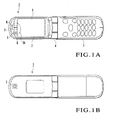
- Figs. 1A and 1B are views showing the outer appearances of the front and rear surfaces, respectively, of a folding portable telephone with a camera function as a portable terminal according to the first embodiment of the present invention. More specifically, Fig. 1A is a view showing the outer appearance of the display side in a state wherein the surface of a display unit housing and the surface of an input unit housing are open apart, and Fig. 1B is a view showing the outer appearance seen from a side opposite to that of FIG. 1A.
- a folding portable telephone 1 includes a display unit housing 2, input unit housing 3, hinge 4, display unit 5, receiving speaker 6, camera unit 7, first sound emission portion 8, second sound emission portion 9, and the like.
- the folding portable telephone 1 is also provided with a battery, a speaker for producing an incoming-call melody or the like, a microphone for receiving voice, and the like.
- the hinge 4 pivotally connects the display unit housing 2 and input unit housing 3. By pivoting the hinge 4, the display unit housing 2 is opened or covered with respect to the input unit housing 3.
- the input unit housing 3 includes buttons to input characters, numerals, and symbols, an operating unit such as a power ON/OFF button, a circuit board, a battery, and the like.
- the display unit housing 2 includes the display unit 5, receiving speaker 6, camera unit 7, and the like.
- the display unit 5 serves to display an image, data such as a telephone number, various types of menus, information such as operation instructions, and the like, and comprises, e.g., an LCD (Liquid Crystal Display).
- the receiving speaker 6 is mounted in the position indicated by the broken line in Fig. 1A, and serves to produce received voice. An output sound from the receiving speaker 6 is emitted to the outside from the first sound emission portion 8 and second sound emission portion 9.
- the voice output method according to this embodiment employs a leak tolerant method which will be described later.
- the camera unit 7 is arranged at the position indicated by the broken line in Fig. 1B.
- the camera unit 7 includes a solid-state image sensor (CCD or the like) and a circuit which converts an image signal, input from an optical system when the camera unit 7 is operated, into a digital signal as image data.
- CCD solid-state image sensor
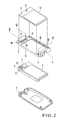
- Fig. 2 is an exploded perspective view of the display unit housing of the portable telephone shown in FIGS. 1A and 1B.
- the display unit housing 2 comprises members such as a front housing 10, rear housing 11, screen 12, and display unit frame 13.
- the receiving speaker 6 and camera unit 7 are disposed on the display unit frame 13.
- the receiving speaker 6 and camera unit 7 are arranged in the vicinity of one side that opposes a side engaging with the hinge 4.
- the camera unit 7 is formed almost at the center in the vicinity of this one side.
- the receiving speaker 6 is disposed at a portion adjacent to the camera unit 7.
- the camera unit 7 includes an auto-focus function and the like and occupies a large area when compared to the receiving speaker 6.
- the receiving speaker 6 and camera unit 7 are formed at a position opposing an earpiece portion 20, as shown in Fig. 1A.
- the earpiece portion 20 refers to a region where the user applies his ear when speaking over the telephone.
- the camera unit 7 is formed almost at the center of the earpiece portion 20.
- the display unit 5 covers a region extending from a portion adjacent to the camera unit 7 and receiving speaker 6 to the vicinity of one side that engages with the hinge 4.
- the front housing 10 and rear housing 11 sandwich the display unit frame 13 and fit with each other to serve as the display unit housing 2.
- a fitting method can include, e.g., a method of fixing with screws, as shown in Fig. 2.
- the rear housing 11 comprises a camera lens and the like.
- the front housing 10 includes a first through hole 21, third through hole 22, groove 23, screen adhering seat surface 24, opening 25, and the like.
- the first through hole 21 and third through hole 22 extend through the front housing 10.
- the first through hole 21 is formed at a position opposing the receiving speaker 6 on the display unit frame 13 when the front housing 10 and rear housing 11 sandwich the display unit frame 13.
- the third through hole 22 is formed at a position opposing the camera unit 7 on the display unit frame 13 when the front housing 10 and rear housing 11 sandwich the display unit frame 13.
- the groove 23 is formed in the front surface of the front housing 10 to communicate the first through hole 21 and third through hole 22.
- the groove 23 is disposed at a position opposing a portion ranging from the receiving speaker 6 to the camera unit 7 when the front housing 10 and rear housing 11 sandwich the display unit frame 13.
- the screen adhering seat surface 24 is a portion to be fixed to the screen 12 through a double-sided tape.
- the opening 25 is provided to allow the display unit 5 visually recognizable.
- the screen 12 covers the surface of the front housing 10 to protect the display unit 5.
- the screen 12 covers a sound guide hole 26 as well as the display unit 5.
- the screen 12 includes a second through hole 31 and fourth through hole 32 which extend through the screen 12.
- the second through hole 31 and fourth through hole 32 are disposed at such positions that they respectively coincide with the first through hole 21 and third through hole 22 formed in the front housing 10, when the screen 12 covers the front housing 10, to form through holes.
- As the material of the screen 12, at least a region which opposes the display unit 5 preferably employs a highly transparent member so that an image displayed on the display unit 5 is visually recognizable.
- the first sound emission portion 8 is formed when the first through hole 21 in the front housing 10 integrates with the second through hole 31 in the screen 12.
- the second sound emission portion 9 is formed when the third through hole 22 in the front housing 10 integrates with the fourth through hole 34 in the screen 12.
- the first sound emission portion 8 and second sound emission portion 9 serve to emit the output sound from the receiving speaker 6 to the outside.
- the second sound emission portion 9 serves as a leak hole to constitute the leak tolerant method as the packaging method of the receiving speaker 6.
- the leak tolerant method refers to a method according to which, in order to reduce the acoustic influence caused by air leak between the receiving speaker and ear, an output sound generating main surface and a surface (rear surface) opposing it, which are usually separated are acoustically coupled to lower the acoustic output impedance of the receiving speaker.
- the earpiece portion 20 includes a sound emission portion (first sound emission portion 8) which emits an output sound from the output sound generating main surface, and a leak portion (second sound emission portion 9) to leak the output sound from the surface opposing the output sound generating main surface.
- the sound guide hole 26 is formed in the portion of the groove 23 of the front housing 10 when the screen 12 covers the front housing 10.
- the sound guide hole 26 serves to communicate the first sound emission portion 8 and second sound emission portion 9 so the output sound from the output sound generating main surface can be emitted from the second sound emission portion as well. Therefore, the second sound emission portion 9 is configured to serve as a leak hole as well as to emit the output sound from the output sound generating main surface.
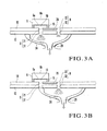
- Figs. 3A and 3B are schematic sectional views showing how the user applies his ear to the earpiece portion 20 of the folding portable telephone 1 to listen to the output sound from the receiving speaker 6.
- Figs. 3A and 3B also schematically show how the output sound is output from the receiving speaker 6.
- the receiving speaker 6 is mounted as it is abutted against the front housing 10 through a cushion 15 fixed to the peripheral portion of the receiving speaker 6.
- the cushion 15 serves not to leak the output sound from an output sound generating main surface 6a, and to prevent water or the like, which might enter from the sound emission portion or the like, from entering the apparatus.
- a space 16 is provided between the receiving speaker 6 and front housing 10.
- Fig. 3A shows a state wherein the first sound emission portion 8 and second sound emission portion 9 formed in the earpiece portion 20 oppose the internal space formed by the user's ear pinna.
- Most of the output sound output from the output sound generating main surface 6a of the receiving speaker 6 is directed to the user's ear pinna through the first sound emission portion 8, passes through an external auditory canal 29, and reaches the eardrum and is sensed.
- an output sound output from a rear surface (to be referred to as "output sound generating sub-surface 6b" hereinafter) on a side opposite to the output sound generating main surface 6a is emitted through the second sound emission portion 9.
- Very small part of the output sound output from the output sound generating main surface 6a of the receiving speaker 6 is emitted from the second sound emission portion 9 through the sound guide hole 26.
- Fig. 3B shows a state wherein the ear helix or the like of the user's ear pinna covers the first sound emission portion 8 and the second sound emission portion 9 opposes the internal space formed by the user's ear pinna.
- the first sound emission portion 8 hardly emits any output sound.
- the output sound output from the output sound generating main surface 6a of the receiving speaker 6 is directed from the second sound emission portion 9 to the user's ear pinna through the sound guide hole 26, passes through the external auditory canal 29, and reaches the eardrum and is sensed.
- the user can obtain a sufficient output sound even if he covers the first sound emission portion 8 with the ear helix or the like of his ear pinna.
- the first sound emission portion 8 is formed in a surface that opposes the receiving speaker 6, and the second sound emission portion is formed in a surface that opposes the camera unit. Even if the ear helix or the like of the ear pinna covers one of the sound emission portions, the user can sense the output sound from the receiving speaker 6 via the other sound emission portion.
- the second sound emission portion is formed at the center of the earpiece portion 20, and the first sound emission portion 8 is formed at a position shifted from the center.
- the ear helix or the like of the user's ear pinna may cover the first sound emission portion 8 at a high possibility. Even in such a case, the above arrangement allows the user to listen to the output sound well. Because of the structure (leak tolerant structure) that allows the user to receive with the earpiece portion the output sound output from the output sound generating sub-surface 6b, a high-quality output sound can be provided.
- the sound guide hole 26 is formed by forming the groove 23 in the front housing 10 and covering the groove 23 with the screen 12. Hence, no earpiece portion need project as in the portable telephone described in reference 1. This enables the folding portable telephone 1 to be made thin, and no design limitations are imposed on the surface of the portable telephone.
- the second sound emission portion 9 is formed at the position adjacent to the portion opposing the receiving speaker 6, the receiving speaker 6 itself need not be made large, eliminating the need for sacrificing downsizing.
- the degrees of freedom of the position to form the receiving speaker 6 can be increased. Therefore, the first embodiment can be employed particularly suitably in a digital portable telephone with a camera or a W-CDMA information communication terminal, in which the receiving speaker 6 must be arranged at a position shifted from the center.
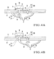
- Figs. 4A and 4B are schematic views to explain how the user listens to an output sound from a receiving speaker 6 in a portable telephone according to this embodiment.
- the basic arrangement and operation of portable telephone according to this embodiment are the same as those of the first embodiment except for the following respects.
- the second embodiment is different from the first embodiment in that although the first embodiment employs the leak tolerant structure, the second embodiment does not employ one, and that the user can listen to only an output sound from an output sound generating main surface 6a with an earpiece portion 20.
- the second embodiment is different from the first embodiment in that although the second sound emission portion 9 of the first embodiment comprises a through hole, a second sound emission portion 109 of the second embodiment comprises a groove structure.
- the second sound emission portion 9 of the first embodiment comprises the third through hole 22 and fourth through hole 32
- the second sound emission portion 109 of the second embodiment comprises a groove 122 connected to a groove 23 that forms a sound guide hole 26, and a fourth through hole 32.
- Fig. 4A shows a state wherein a first sound emission portion 8 and the second sound emission portion 109 oppose internal space formed by the user's ear pinna.
- the output sound output from the output sound generating main surface 6a of the receiving speaker 6 is directed to the user's ear pinna through the first sound emission portion 8, passes through an external auditory canal 29, and reaches the eardrum and is sensed.
- the output sound output from the output sound generating main surface 6a of the receiving speaker 6 is directed to the user's ear pinna through the sound guide hole 26 communicating with the first sound emission portion 8, and the second sound emission portion 109, passes through the external auditory canal 29, and reaches the eardrum and is sensed.
- Fig. 4B shows a state wherein the ear helix or the like of the user's ear pinna covers the first sound emission portion 8 and the second sound emission portion 109 opposes the internal space formed by the user's ear pinna.
- the output sound output from the output sound generating main surface 6a of the receiving speaker 6 is directed to the user's ear pinna through mainly the sound guide hole 26 and second sound emission portion 109, passes through the external auditory canal 29, and reaches the eardrum and is sensed.
- the first sound emission portion 8 is formed in a surface that opposes the receiving speaker 6, and the second sound emission portion 109 is formed in a surface that opposes a camera unit 7. Even if the ear helix or the like of the ear pinna covers one of the sound emission portions, the user can sense the output sound from the receiving speaker 6 via the other sound emission portion.
- the second sound emission portion 109 is formed at the center of the earpiece portion 20, and the first sound emission portion 8 is formed at a position shifted from the center.
- the ear helix or the like of the user's ear pinna may cover the first sound emission portion 8 at a high possibility. Even in such a case, the above arrangement allows the user to listen to the output sound well.
- the first and second embodiments exemplified a case wherein one first sound emission portion 8 and one second sound emission portion 9 (109) are disposed.
- the present invention is not limited to this, but the first sound emission portion 8 may comprises a plurality of first sound emission portions, and the second sound emission portion 9 (109) may comprise a plurality of second sound emission portions.
- the first sound emission portion 8 may comprises a plurality of first sound emission portions
- the second sound emission portion 9 (109) may comprise a plurality of second sound emission portions.
- three through holes may be provided to form a second sound emission portion 209.
- An earpiece portion 20 was provided with a first sound emission portion 8 which opposed a receiving speaker 6, and a second sound emission portion 9 which leaked an output sound produced from an output sound generating sub-surface 6b of the receiving speaker 6.
- a sound guide hole 26 communicated the first sound emission portion 8 and second sound emission portion 9.
- the sound guide hole 26 had a depth of 0.25 mm, a width of 1.2 mm, and a length of 7 mm.
- a portable telephone as a comparative example had the same arrangement as that of the above practical example except that it had no sound guide hole 26.
- the characteristics of the sound pressure, output from the receiving speaker 6 to the outside, as a function of the frequency were measured for each of the practical example and the comparative example.
- the measurement took place under conditions that reproduced a state wherein the first sound emission portion 8 and second sound emission portion 9 provided to the earpiece portion 20 opposed the internal space formed by the user's ear pinna, as shown in Fig. 3A, and a state wherein the ear helix or the like of the user's ear pinna covered the first sound emission portion 8 and the second sound emission portion 9 opposed the internal space formed by the user's ear pinna, as shown in Fig. 3B.
- Fig. 6 shows the results obtained by measuring the characteristics of the sound pressure as a function of the frequency of the receiving speaker 6, of a portable telephone 1 according to this practical example.
- the sound pressure was plotted as a function of the frequency.
- (a) shows the result of measurement when none of the first sound emission portion 8 and second sound emission portion 9 was covered
- (b) shows the result of measurement when only the first sound emission portion 8 was covered.
- the sound pressure was about 103 dBspl, as indicated by (a).
- the sound pressure was about 100 dBspl, as indicated by (b).
- Fig. 7 shows results obtained by measuring the characteristics of the sound pressure as a function of the frequency, of a receiving speaker 6 of a portable telephone as a comparative example.
- a curve (a) shows the result of measurement when none of a first sound emission portion 8 and a second sound emission portion 9 was covered, and (b) shows the result of measurement when only the first sound emission portion 8 was covered.
- the sound pressure was about 100 dBspl, as indicated by (a).
- the sound pressure was about 50 dBspl, as indicated by (b).
- the sound pressure drops by 50 dB from that of the case wherein none of the first sound emission portion 8 and second sound emission portion 9 is covered. Furthermore, when the frequency was 500 Hz, the sound pressure dropped by about 64 dB. At the frequency of 500 Hz, when the first sound emission portion 8 was covered, the actual sound pressure was about 36 dBspl. Only an output sound that the user considered silent was produced.
- the sound pressure drop amount could be decreased to 1/10 or less that of the comparative example.
- An output sound that caused no problem on the practical level could be emitted.
Landscapes
- Physics & Mathematics (AREA)
- Acoustics & Sound (AREA)
- Engineering & Computer Science (AREA)
- Signal Processing (AREA)
- Health & Medical Sciences (AREA)
- Otolaryngology (AREA)
- Telephone Set Structure (AREA)
- Details Of Audible-Bandwidth Transducers (AREA)
Abstract
Description
- The present invention relates to various types of portable terminals such as a portable telephone, a PHS (Personal Handyphon System), and other information portable terminals.
- In a portable telephone, generally, a housing accommodates a receiving speaker, and a through hole is formed to extend from the receiving speaker accommodating portion to the outside. When speaking over the telephone, the user applies his ear over the through hole, and speaks while listening to the output sound produced by the receiving speaker through the through hole. As the structure of the through hole, the following ones have been proposed.
- As the first prior art, reference 1 (
Japanese Patent Laid-Open No. 10-304036 - As the second prior art, reference 2 (
Japanese Patent Laid-Open No. 2000-244618 - As the third prior art, reference 3 (
Japanese Patent Laid-Open No. 2001-230841 - When the user applies his ear to the earpiece portion for speaking over the telephone, he may undesirably cover the through hole with his ear helix, earlobe, or the like (to be merely referred to as an "ear helix or the like" hereinafter). In this case, the output sound volume decreases greatly. To solve this problem, a plurality of through holes may extend from the receiving speaker. Also, the size of the receiving speaker itself may be increased to enlarge the formation region of the through hole that opposes the receiving speaker.
- Currently, considerable downsizing demands arise for portable terminals represented by a portable telephone, and the downsizing demands for electronic components to be mounted in the portable terminals are also strong. The receiving speaker is no exception and also faces a strong downsizing demand. To make the receiving speaker large is accordingly difficult. Even if a plurality of through holes are formed in a downsized receiving speaker, the ear helix or the like may undesirably cover all of the plurality of through holes.
- Recently, a portable telephone with a camera, which has a multifunction of both a camera and a portable telephone, is becoming popular. For example, a technique has been proposed with which a CCD (Charge Coupled Device) camera and a liquid crystal screen are arranged on the front surface of the telephone main body. The CCD camera can capture the user's face, and the captured image can be transmitted to the other party. A W-CDMA (Wideband Code Division Multiple Access) portable telephone has also been proposed which can send the motion image captured by the user to the other party. As a portable telephone incorporating a storage medium such as an SD card becomes popular, the performance of the camera mounted in the portable telephone has improved remarkably. Regarding the pixel number, it exceeded one million and reached two million. A product mounted with a camera that has an auto-focus function is also on the market.
- From this background, a camera mounted in a portable telephone tends to be large regardless of the need for a compact portable telephone. This tendency forces the receiving speaker, which is conventionally arranged near the center of the housing, to be arranged on the outer side of the housing. More specifically, although the receiving speaker is conventionally arranged to oppose almost the center of the earpiece, it cannot but be arranged at the end of the earpiece portion. Under these circumstances, when the user speaks over the telephone while applying his ear to the earpiece portion, he may undesirably cover the through hole with his ear helix or the like, and the output sound may not reach the user with a sufficient volume at a possibility worse than in a conventional case.
- According to the technique described in
reference 1, as the earpiece portion must project, the thickness of the portable telephone inevitably increases. - The present invention has been made in view of the above background, and has as its object to provide a portable terminal which can emit an output sound stably regardless of what position of the earpiece portion the user's ear pinna may oppose, while achieving downsizing and thickness reduction.
- A portable terminal according to the present invention comprises a housing which incorporates a display unit and a receiving speaker, an earpiece portion which allows a user to listen to an output sound from the receiving speaker, a first sound emission portion and a second sound emission portion which guide the output sound from the receiving speaker to the earpiece portion, a sound guide hole which communicates the first sound emission portion and the second sound emission portion, and a screen which protects the display unit, wherein the first sound emission portion is formed at a position opposing an output sound generating main surface of the receiving speaker, the second sound emission portion is formed at a portion adjacent to the position opposing the output sound generating main surface of the receiving speaker, and the sound guide hole is formed by covering a groove with the screen, the groove being formed in the housing to connect the first sound emission portion and the second sound emission portion.
- According to the present invention, the second sound emission portion is arranged at the portion adjacent to the position opposing the output sound generating main surface of the receiving speaker. Even when the ear helix or the like of the user's ear pinna covers the first sound emission portion located at the position opposing the output sound generating main surface, the user can listen to the output sound from the second sound emission portion through the sound guide hole. The first sound emission portion is formed at the position opposing the receiving speaker, and the second sound emission portion is formed at the portion adjacent to the position opposing the receiving speaker. Thus, the first sound emission portion and second sound emission portion can be arranged to be appropriately spaced apart from each other in the earpiece. This provides a portable terminal that can emit an output sound stably regardless of what position of the earpiece portion the user's ear pinna opposes.
- The sound guide hole for guiding the second to the second sound emission portion is formed by only covering the groove formed in the housing surface with the screen. The sound guide hole can therefore be formed without changing the thickness of the portable telephone. As the second sound emission portion is formed at a position other than the surface that opposes the receiving speaker, the receiving speaker can be further downsized. The presence of the second sound emission portion increases the degrees of design freedom of the position where the receiving speaker can be formed.
- Therefore, the present invention can advantageously provide a portable terminal which can emit an output sound stably regardless of what position of the earpiece portion the user's ear pinna may oppose, while achieving downsizing and thickness reduction.
-
- Fig. 1A is a view showing the outer appearance of the display side of a portable telephone according to the first embodiment of the present invention, in a state wherein the surface of a display unit housing and the surface of an input unit housing are open apart;
- Fig. 1B is a view showing the outer appearance of the portable telephone according to the first embodiment of the present invention seen from a side opposite to that of FIG. 1A;
- Fig. 2 is an exploded perspective view of the display unit housing of the portable telephone shown in FIGS. 1A and 1B;
- Fig. 3A is a sectional view showing a state wherein a first sound emission portion and second sound emission portion oppose internal space formed by the user's ear pinna;
- Fig. 3B is a sectional view showing a state wherein the ear helix or the like of the user's ear pinna covers the first sound emission portion and the second sound emission portion opposes the internal space formed by the user's ear pinna;
- Fig. 4A is a sectional view showing a state in the second embodiment of the present invention wherein a first sound emission portion and second sound emission portion oppose internal space formed by the user's ear pinna;
- Fig. 4B is a sectional view showing a state in the second embodiment of the present invention wherein the ear helix or the like of the user's ear pinna covers the first sound emission portion and the second sound emission portion opposes the internal space formed by the user's ear pinna;
- Fig. 5 is a view showing the outer appearance of a portable telephone including a plurality of second sound emission portions;
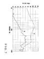
- Fig. 6 is a graph obtained by plotting the sound pressure as a function of the frequency in a portable telephone according to a practical example of the present invention; and
- Fig. 7 is a graph obtained by plotting the sound pressure as a function of the frequency in a portable telephone as a comparative example.
- Embodiments to which the present invention is applied will be described in detail with reference to the drawings. Note that any other embodiments can also belong to the category of the present invention as far as they comply with the scope of the present invention.
- Figs. 1A and 1B are views showing the outer appearances of the front and rear surfaces, respectively, of a folding portable telephone with a camera function as a portable terminal according to the first embodiment of the present invention. More specifically, Fig. 1A is a view showing the outer appearance of the display side in a state wherein the surface of a display unit housing and the surface of an input unit housing are open apart, and Fig. 1B is a view showing the outer appearance seen from a side opposite to that of FIG. 1A. As shown in Figs. 1A and 1B, a folding
portable telephone 1 includes a display unit housing 2,input unit housing 3,hinge 4,display unit 5, receivingspeaker 6,camera unit 7, firstsound emission portion 8, secondsound emission portion 9, and the like. Although not illustrated, the foldingportable telephone 1 is also provided with a battery, a speaker for producing an incoming-call melody or the like, a microphone for receiving voice, and the like. - The
hinge 4 pivotally connects the display unit housing 2 andinput unit housing 3. By pivoting thehinge 4, the display unit housing 2 is opened or covered with respect to theinput unit housing 3. Theinput unit housing 3 includes buttons to input characters, numerals, and symbols, an operating unit such as a power ON/OFF button, a circuit board, a battery, and the like. The display unit housing 2 includes thedisplay unit 5, receivingspeaker 6,camera unit 7, and the like. - The
display unit 5 serves to display an image, data such as a telephone number, various types of menus, information such as operation instructions, and the like, and comprises, e.g., an LCD (Liquid Crystal Display). The receivingspeaker 6 is mounted in the position indicated by the broken line in Fig. 1A, and serves to produce received voice. An output sound from the receivingspeaker 6 is emitted to the outside from the firstsound emission portion 8 and secondsound emission portion 9. The voice output method according to this embodiment employs a leak tolerant method which will be described later. Thecamera unit 7 is arranged at the position indicated by the broken line in Fig. 1B. Thecamera unit 7 includes a solid-state image sensor (CCD or the like) and a circuit which converts an image signal, input from an optical system when thecamera unit 7 is operated, into a digital signal as image data. - Fig. 2 is an exploded perspective view of the display unit housing of the portable telephone shown in FIGS. 1A and 1B. As shown in Fig. 2, the display unit housing 2 comprises members such as a
front housing 10,rear housing 11,screen 12, anddisplay unit frame 13. - In addition to the
display unit 5, the receivingspeaker 6 andcamera unit 7 are disposed on thedisplay unit frame 13. The receivingspeaker 6 andcamera unit 7 are arranged in the vicinity of one side that opposes a side engaging with thehinge 4. Thecamera unit 7 is formed almost at the center in the vicinity of this one side. The receivingspeaker 6 is disposed at a portion adjacent to thecamera unit 7. Thecamera unit 7 includes an auto-focus function and the like and occupies a large area when compared to the receivingspeaker 6. - The receiving
speaker 6 andcamera unit 7 are formed at a position opposing anearpiece portion 20, as shown in Fig. 1A. Theearpiece portion 20 refers to a region where the user applies his ear when speaking over the telephone. Thecamera unit 7 is formed almost at the center of theearpiece portion 20. Thedisplay unit 5 covers a region extending from a portion adjacent to thecamera unit 7 and receivingspeaker 6 to the vicinity of one side that engages with thehinge 4. - The
front housing 10 andrear housing 11 sandwich thedisplay unit frame 13 and fit with each other to serve as the display unit housing 2. A fitting method can include, e.g., a method of fixing with screws, as shown in Fig. 2. Therear housing 11 comprises a camera lens and the like. - The
front housing 10 includes a first throughhole 21, third throughhole 22,groove 23, screen adhering seat surface 24, opening 25, and the like. The first throughhole 21 and third throughhole 22 extend through thefront housing 10. The first throughhole 21 is formed at a position opposing the receivingspeaker 6 on thedisplay unit frame 13 when thefront housing 10 andrear housing 11 sandwich thedisplay unit frame 13. The third throughhole 22 is formed at a position opposing thecamera unit 7 on thedisplay unit frame 13 when thefront housing 10 andrear housing 11 sandwich thedisplay unit frame 13. Thegroove 23 is formed in the front surface of thefront housing 10 to communicate the first throughhole 21 and third throughhole 22. Accordingly, thegroove 23 is disposed at a position opposing a portion ranging from the receivingspeaker 6 to thecamera unit 7 when thefront housing 10 andrear housing 11 sandwich thedisplay unit frame 13. The screen adhering seat surface 24 is a portion to be fixed to thescreen 12 through a double-sided tape. Theopening 25 is provided to allow thedisplay unit 5 visually recognizable. - The
screen 12 covers the surface of thefront housing 10 to protect thedisplay unit 5. In this embodiment, thescreen 12 covers asound guide hole 26 as well as thedisplay unit 5. Thescreen 12 includes a second throughhole 31 and fourth throughhole 32 which extend through thescreen 12. The second throughhole 31 and fourth throughhole 32 are disposed at such positions that they respectively coincide with the first throughhole 21 and third throughhole 22 formed in thefront housing 10, when thescreen 12 covers thefront housing 10, to form through holes. As the material of thescreen 12, at least a region which opposes thedisplay unit 5 preferably employs a highly transparent member so that an image displayed on thedisplay unit 5 is visually recognizable. - The first
sound emission portion 8 is formed when the first throughhole 21 in thefront housing 10 integrates with the second throughhole 31 in thescreen 12. The secondsound emission portion 9 is formed when the third throughhole 22 in thefront housing 10 integrates with the fourth through hole 34 in thescreen 12. The firstsound emission portion 8 and secondsound emission portion 9 serve to emit the output sound from the receivingspeaker 6 to the outside. The secondsound emission portion 9 serves as a leak hole to constitute the leak tolerant method as the packaging method of the receivingspeaker 6. The leak tolerant method refers to a method according to which, in order to reduce the acoustic influence caused by air leak between the receiving speaker and ear, an output sound generating main surface and a surface (rear surface) opposing it, which are usually separated are acoustically coupled to lower the acoustic output impedance of the receiving speaker. In this embodiment, theearpiece portion 20 includes a sound emission portion (first sound emission portion 8) which emits an output sound from the output sound generating main surface, and a leak portion (second sound emission portion 9) to leak the output sound from the surface opposing the output sound generating main surface. - The
sound guide hole 26 is formed in the portion of thegroove 23 of thefront housing 10 when thescreen 12 covers thefront housing 10. Thesound guide hole 26 serves to communicate the firstsound emission portion 8 and secondsound emission portion 9 so the output sound from the output sound generating main surface can be emitted from the second sound emission portion as well. Therefore, the secondsound emission portion 9 is configured to serve as a leak hole as well as to emit the output sound from the output sound generating main surface. - Figs. 3A and 3B are schematic sectional views showing how the user applies his ear to the
earpiece portion 20 of the foldingportable telephone 1 to listen to the output sound from the receivingspeaker 6. Figs. 3A and 3B also schematically show how the output sound is output from the receivingspeaker 6. - The receiving
speaker 6 is mounted as it is abutted against thefront housing 10 through acushion 15 fixed to the peripheral portion of the receivingspeaker 6. Thecushion 15 serves not to leak the output sound from an output sound generatingmain surface 6a, and to prevent water or the like, which might enter from the sound emission portion or the like, from entering the apparatus. Aspace 16 is provided between the receivingspeaker 6 andfront housing 10. - Fig. 3A shows a state wherein the first
sound emission portion 8 and secondsound emission portion 9 formed in theearpiece portion 20 oppose the internal space formed by the user's ear pinna. Most of the output sound output from the output sound generatingmain surface 6a of the receivingspeaker 6 is directed to the user's ear pinna through the firstsound emission portion 8, passes through an externalauditory canal 29, and reaches the eardrum and is sensed. Regarding the second sound emission portion, an output sound output from a rear surface (to be referred to as "outputsound generating sub-surface 6b" hereinafter) on a side opposite to the output sound generatingmain surface 6a is emitted through the secondsound emission portion 9. Very small part of the output sound output from the output sound generatingmain surface 6a of the receivingspeaker 6 is emitted from the secondsound emission portion 9 through thesound guide hole 26. - Fig. 3B shows a state wherein the ear helix or the like of the user's ear pinna covers the first
sound emission portion 8 and the secondsound emission portion 9 opposes the internal space formed by the user's ear pinna. In this case, as the user's ear pinna covers the firstsound emission portion 8, the firstsound emission portion 8 hardly emits any output sound. Instead, the output sound output from the output sound generatingmain surface 6a of the receivingspeaker 6 is directed from the secondsound emission portion 9 to the user's ear pinna through thesound guide hole 26, passes through the externalauditory canal 29, and reaches the eardrum and is sensed. Thus, the user can obtain a sufficient output sound even if he covers the firstsound emission portion 8 with the ear helix or the like of his ear pinna. - According to this embodiment, the first
sound emission portion 8 is formed in a surface that opposes the receivingspeaker 6, and the second sound emission portion is formed in a surface that opposes the camera unit. Even if the ear helix or the like of the ear pinna covers one of the sound emission portions, the user can sense the output sound from the receivingspeaker 6 via the other sound emission portion. In this embodiment, the second sound emission portion is formed at the center of theearpiece portion 20, and the firstsound emission portion 8 is formed at a position shifted from the center. Hence, the ear helix or the like of the user's ear pinna may cover the firstsound emission portion 8 at a high possibility. Even in such a case, the above arrangement allows the user to listen to the output sound well. Because of the structure (leak tolerant structure) that allows the user to receive with the earpiece portion the output sound output from the outputsound generating sub-surface 6b, a high-quality output sound can be provided. - The
sound guide hole 26 is formed by forming thegroove 23 in thefront housing 10 and covering thegroove 23 with thescreen 12. Hence, no earpiece portion need project as in the portable telephone described inreference 1. This enables the foldingportable telephone 1 to be made thin, and no design limitations are imposed on the surface of the portable telephone. As the secondsound emission portion 9 is formed at the position adjacent to the portion opposing the receivingspeaker 6, the receivingspeaker 6 itself need not be made large, eliminating the need for sacrificing downsizing. As the user can listen to the output sound from the output sound generatingmain surface 6a via the secondsound emission portion 9 which does not oppose the receivingspeaker 6, the degrees of freedom of the position to form the receivingspeaker 6 can be increased. Therefore, the first embodiment can be employed particularly suitably in a digital portable telephone with a camera or a W-CDMA information communication terminal, in which the receivingspeaker 6 must be arranged at a position shifted from the center. - The second embodiment of the present invention will be described hereinafter. In the following description, the same elements and members as those of the first embodiment are denoted by the same reference numerals and will not be illustrated when appropriate.
- Figs. 4A and 4B are schematic views to explain how the user listens to an output sound from a receiving
speaker 6 in a portable telephone according to this embodiment. The basic arrangement and operation of portable telephone according to this embodiment are the same as those of the first embodiment except for the following respects. More specifically, the second embodiment is different from the first embodiment in that although the first embodiment employs the leak tolerant structure, the second embodiment does not employ one, and that the user can listen to only an output sound from an output sound generatingmain surface 6a with anearpiece portion 20. In other words, the second embodiment is different from the first embodiment in that although the secondsound emission portion 9 of the first embodiment comprises a through hole, a secondsound emission portion 109 of the second embodiment comprises a groove structure. More specifically, although the secondsound emission portion 9 of the first embodiment comprises the third throughhole 22 and fourth throughhole 32, the secondsound emission portion 109 of the second embodiment comprises agroove 122 connected to agroove 23 that forms asound guide hole 26, and a fourth throughhole 32. - Fig. 4A shows a state wherein a first
sound emission portion 8 and the secondsound emission portion 109 oppose internal space formed by the user's ear pinna. The output sound output from the output sound generatingmain surface 6a of the receivingspeaker 6 is directed to the user's ear pinna through the firstsound emission portion 8, passes through an externalauditory canal 29, and reaches the eardrum and is sensed. The output sound output from the output sound generatingmain surface 6a of the receivingspeaker 6 is directed to the user's ear pinna through thesound guide hole 26 communicating with the firstsound emission portion 8, and the secondsound emission portion 109, passes through the externalauditory canal 29, and reaches the eardrum and is sensed. - Fig. 4B shows a state wherein the ear helix or the like of the user's ear pinna covers the first
sound emission portion 8 and the secondsound emission portion 109 opposes the internal space formed by the user's ear pinna. In this case, as the user's ear pinna covers the firstsound emission portion 8, the output sound output from the output sound generatingmain surface 6a of the receivingspeaker 6 is directed to the user's ear pinna through mainly thesound guide hole 26 and secondsound emission portion 109, passes through the externalauditory canal 29, and reaches the eardrum and is sensed. - According to this embodiment, the first
sound emission portion 8 is formed in a surface that opposes the receivingspeaker 6, and the secondsound emission portion 109 is formed in a surface that opposes acamera unit 7. Even if the ear helix or the like of the ear pinna covers one of the sound emission portions, the user can sense the output sound from the receivingspeaker 6 via the other sound emission portion. In this embodiment, the secondsound emission portion 109 is formed at the center of theearpiece portion 20, and the firstsound emission portion 8 is formed at a position shifted from the center. Hence, the ear helix or the like of the user's ear pinna may cover the firstsound emission portion 8 at a high possibility. Even in such a case, the above arrangement allows the user to listen to the output sound well. - The first and second embodiments exemplified a case wherein one first
sound emission portion 8 and one second sound emission portion 9 (109) are disposed. However, the present invention is not limited to this, but the firstsound emission portion 8 may comprises a plurality of first sound emission portions, and the second sound emission portion 9 (109) may comprise a plurality of second sound emission portions. For example, as shown in Fig. 5, three through holes may be provided to form a secondsound emission portion 209. - The embodiments described above will be described in more detail. Note that the following practical example does not limit the scope of the present invention at all.
- A portable telephone according to the practical example employed the receiving system of the receiving
speaker 6 of theportable telephone 1 according to the first embodiment was employed (see Figs. 3A and 3B). More specifically, the leak tolerant structure was employed. Anearpiece portion 20 was provided with a firstsound emission portion 8 which opposed a receivingspeaker 6, and a secondsound emission portion 9 which leaked an output sound produced from an output sound generating sub-surface 6b of the receivingspeaker 6. Asound guide hole 26 communicated the firstsound emission portion 8 and secondsound emission portion 9. Thesound guide hole 26 had a depth of 0.25 mm, a width of 1.2 mm, and a length of 7 mm. A portable telephone as a comparative example had the same arrangement as that of the above practical example except that it had nosound guide hole 26. - The characteristics of the sound pressure, output from the receiving
speaker 6 to the outside, as a function of the frequency were measured for each of the practical example and the comparative example. The measurement took place under conditions that reproduced a state wherein the firstsound emission portion 8 and secondsound emission portion 9 provided to theearpiece portion 20 opposed the internal space formed by the user's ear pinna, as shown in Fig. 3A, and a state wherein the ear helix or the like of the user's ear pinna covered the firstsound emission portion 8 and the secondsound emission portion 9 opposed the internal space formed by the user's ear pinna, as shown in Fig. 3B. - Fig. 6 shows the results obtained by measuring the characteristics of the sound pressure as a function of the frequency of the receiving
speaker 6, of aportable telephone 1 according to this practical example. In Fig. 6, the sound pressure was plotted as a function of the frequency. In Fig. 6, (a) shows the result of measurement when none of the firstsound emission portion 8 and secondsound emission portion 9 was covered, and (b) shows the result of measurement when only the firstsound emission portion 8 was covered. When the firstsound emission portion 8 was not covered, at 1 kHz, the sound pressure was about 103 dBspl, as indicated by (a). When the firstsound emission portion 8 was covered, at 1 kHz, the sound pressure was about 100 dBspl, as indicated by (b). These results confirmed that even when the firstsound emission portion 8 was covered, the sound pressure dropped by approximately 3 dB from that of the case wherein none of the firstsound emission portion 8 and secondsound emission portion 9 was covered, which imposed no particular problem in practice. - Fig. 7 shows results obtained by measuring the characteristics of the sound pressure as a function of the frequency, of a receiving
speaker 6 of a portable telephone as a comparative example. In Fig. 7, a curve (a) shows the result of measurement when none of a firstsound emission portion 8 and a secondsound emission portion 9 was covered, and (b) shows the result of measurement when only the firstsound emission portion 8 was covered. When the firstsound emission portion 8 was not covered, at 1 kHz, the sound pressure was about 100 dBspl, as indicated by (a). When the firstsound emission portion 8 was covered, at 1 kHz, the sound pressure was about 50 dBspl, as indicated by (b). This suggests that when the firstsound emission portion 8 is covered, the sound pressure drops by 50 dB from that of the case wherein none of the firstsound emission portion 8 and secondsound emission portion 9 is covered. Furthermore, when the frequency was 500 Hz, the sound pressure dropped by about 64 dB. At the frequency of 500 Hz, when the firstsound emission portion 8 was covered, the actual sound pressure was about 36 dBspl. Only an output sound that the user considered silent was produced. - According to this practical example, even when the first
sound emission portion 8 was covered, the sound pressure drop amount could be decreased to 1/10 or less that of the comparative example. An output sound that caused no problem on the practical level could be emitted.
Claims (8)
- A portable terminal characterized by comprising:a housing which incorporates a display unit and a receiving speaker;an earpiece portion which allows a user to listen to an output sound from said receiving speaker;a first sound emission portion and a second sound emission portion which guide the output sound from said receiving speaker to said earpiece portion;a sound guide hole which communicates said first sound emission portion and said second sound emission portion; anda screen which protects said display unit,wherein said first sound emission portion is formed at a position opposing an output sound generating main surface of said receiving speaker,said second sound emission portion is formed at a portion adjacent to the position opposing said output sound generating main surface of said receiving speaker, andsaid sound guide hole is formed by covering a groove with a screen, said groove being formed in said housing to connect said first sound emission portion and said second sound emission portion.
- A portable terminal according to claim 1, characterized in that said second sound emission portion is formed to emit the output sound generated by said output sound generating main surface of said receiving speaker to the outside and to emit an output sound generated from a surface other than said output sound generating main surface of said receiving speaker to the outside.
- A portable terminal according to claim 1, characterized in that said second sound emission portion is located at substantially a center of said earpiece portion.
- A portable terminal according to claim 1, characterized in that said first sound emission portion comprises
a first through hole extending through said housing, and
a second through hole extending through said screen. - A portable terminal according to claim 4, characterized in that said second sound emission portion comprises
a third through hole extending through said housing, and
a fourth through hole extending through said screen. - A portable terminal according to claim 4, characterized in that said second sound emission portion comprises
a groove structure which is formed on said housing and connected to said groove, and
a fourth through hole extending through said screen. - A portable terminal according to claim 1, characterized in that at least one of said first sound emission portion and said second sound emission portion comprises a plurality of sound emission portions.
- A portable terminal according to claim 1, characterized by further comprising a camera unit incorporated in said housing,
wherein said earpiece portion opposes said receiving speaker and said camera unit which are incorporated in said housing,
said camera unit is arranged at substantially a center of said earpiece portion, and
said second sound emission portion opposes said camera unit.
Applications Claiming Priority (2)
| Application Number | Priority Date | Filing Date | Title |
|---|---|---|---|
| JP2005092145A JP2006279260A (en) | 2005-03-28 | 2005-03-28 | Portable terminal |
| PCT/JP2006/306320 WO2006104156A1 (en) | 2005-03-28 | 2006-03-28 | Portable terminal |
Publications (3)
| Publication Number | Publication Date |
|---|---|
| EP1865690A1 true EP1865690A1 (en) | 2007-12-12 |
| EP1865690A4 EP1865690A4 (en) | 2011-05-04 |
| EP1865690B1 EP1865690B1 (en) | 2014-09-17 |
Family
ID=37053412
Family Applications (1)
| Application Number | Title | Priority Date | Filing Date |
|---|---|---|---|
| EP06730268.7A Expired - Lifetime EP1865690B1 (en) | 2005-03-28 | 2006-03-28 | Portable terminal |
Country Status (5)
| Country | Link |
|---|---|
| US (2) | US8340708B2 (en) |
| EP (1) | EP1865690B1 (en) |
| JP (1) | JP2006279260A (en) |
| CN (1) | CN101151875B (en) |
| WO (1) | WO2006104156A1 (en) |
Cited By (3)
| Publication number | Priority date | Publication date | Assignee | Title |
|---|---|---|---|---|
| EP2288177A1 (en) * | 2009-08-20 | 2011-02-23 | Research In Motion Limited | A front resonator for a speaker of a wireless device |
| US8118134B2 (en) | 2009-08-20 | 2012-02-21 | Research In Motion Limited | Front resonator for a speaker of a wireless device |
| EP2723097A3 (en) * | 2012-10-22 | 2015-10-14 | Samsung Electronics Co., Ltd | Microphone module for an electronic device |
Families Citing this family (20)
| Publication number | Priority date | Publication date | Assignee | Title |
|---|---|---|---|---|
| JP2008096351A (en) * | 2006-10-13 | 2008-04-24 | Tlv Co Ltd | Vibrometer |
| JP2008096350A (en) * | 2006-10-13 | 2008-04-24 | Tlv Co Ltd | Vibrometer |
| JP4747086B2 (en) * | 2006-12-26 | 2011-08-10 | Necカシオモバイルコミュニケーションズ株式会社 | Portable terminal |
| US9602914B2 (en) * | 2010-08-27 | 2017-03-21 | Apple Inc. | Porting audio using a connector in a small form factor electronic device |
| CN103221896B (en) * | 2010-08-19 | 2017-06-09 | 苹果公司 | Portable electric appts |
| CN102480891B (en) * | 2010-11-30 | 2014-10-08 | 富泰华工业(深圳)有限公司 | Electronic device |
| JP5695919B2 (en) * | 2011-01-26 | 2015-04-08 | 京セラ株式会社 | Mobile phone |
| KR101991504B1 (en) | 2012-02-24 | 2019-09-30 | 삼성전자주식회사 | Speaker module and portable terminal having duct |
| US8807409B2 (en) * | 2012-12-12 | 2014-08-19 | Htc Corporation | Car holder |
| JP6175261B2 (en) | 2013-03-27 | 2017-08-02 | 京セラ株式会社 | Electronic equipment with microphone |
| CN104580612B (en) * | 2013-10-22 | 2019-02-05 | 联想(北京)有限公司 | The earphone device of communicating terminal and communicating terminal including the earphone device |
| TWI602441B (en) * | 2016-07-11 | 2017-10-11 | 宏碁股份有限公司 | Speaker with harmonic sound and electronic device using the same |
| KR102644176B1 (en) | 2016-11-09 | 2024-03-07 | 삼성전자주식회사 | Electronic device |
| DK3565224T3 (en) * | 2018-05-04 | 2020-08-24 | Guangdong Oppo Mobile Telecommunications Corp Ltd | MOBILE TERMINAL |
| CN108965522B (en) * | 2018-07-10 | 2020-10-16 | 维沃移动通信有限公司 | A receiver module and terminal equipment |
| KR102593275B1 (en) | 2018-11-15 | 2023-10-25 | 삼성전자주식회사 | Display apparatus |
| CN109951582B (en) * | 2019-02-28 | 2021-02-19 | 维沃移动通信有限公司 | A kind of mobile terminal and sound output control method |
| CN110166587B (en) * | 2019-04-24 | 2021-08-03 | 维沃移动通信有限公司 | a mobile terminal |
| CN110113453B (en) * | 2019-04-24 | 2021-04-06 | 维沃移动通信有限公司 | a mobile terminal |
| CN111614824B (en) * | 2020-05-20 | 2021-07-13 | 维沃移动通信有限公司 | Electronic equipment |
Family Cites Families (19)
| Publication number | Priority date | Publication date | Assignee | Title |
|---|---|---|---|---|
| US5790679A (en) * | 1996-06-06 | 1998-08-04 | Northern Telecom Limited | Communications terminal having a single transducer for handset and handsfree receive functionality |
| JPH10304036A (en) | 1997-04-23 | 1998-11-13 | Hosiden Corp | Electroacoustic transducer for receiver |
| FI115108B (en) | 1997-10-06 | 2005-02-28 | Nokia Corp | Method and arrangement for improving earphone leakage resistance in a radio device |
| US6134336A (en) * | 1998-05-14 | 2000-10-17 | Motorola, Inc. | Integrated speaker assembly of a portable electronic device |
| DK173789B1 (en) * | 1998-10-05 | 2001-10-22 | Kirk Acoustics As | Electroacoustic communication device |
| JP3266132B2 (en) | 1999-02-24 | 2002-03-18 | 日本電気株式会社 | Foldable mobile phone |
| GB2355128B (en) * | 1999-10-08 | 2003-04-09 | Nokia Mobile Phones Ltd | Portable electronics device |
| JP2001230841A (en) | 2000-02-18 | 2001-08-24 | Matsushita Electric Ind Co Ltd | Mobile terminal |
| US20020127974A1 (en) * | 2001-03-09 | 2002-09-12 | Song Chang June | Shielded speaker for wireless telephones |
| JP2003224640A (en) * | 2002-01-30 | 2003-08-08 | Mitsubishi Electric Corp | Mobile terminal |
| JP2003319027A (en) | 2002-04-23 | 2003-11-07 | Nec Corp | Portable communication terminal with camera |
| JP2004170575A (en) | 2002-11-19 | 2004-06-17 | Nippon Zeon Co Ltd | Portable electronic equipment with imaging device |
| US7058366B2 (en) * | 2002-12-09 | 2006-06-06 | Sony Ericsson Mobile Communications Ab | Wireless terminal providing sound pressure level dissipation through channeled porting of sound |
| JP4153352B2 (en) * | 2003-04-21 | 2008-09-24 | 松下電器産業株式会社 | Mobile terminal device |
| US7197332B2 (en) * | 2003-04-23 | 2007-03-27 | Nokia Corporation | Multi-function two panel electronic device with 360° relative motion |
| JP2005006205A (en) * | 2003-06-13 | 2005-01-06 | Fujitsu Ltd | Mobile terminal |
| JP4230847B2 (en) | 2003-07-11 | 2009-02-25 | 株式会社東芝 | Mobile terminal device |
| KR100595705B1 (en) * | 2003-12-10 | 2006-06-30 | 엘지전자 주식회사 | Sound output reinforcement device of portable terminal |
| JP2006060398A (en) * | 2004-08-18 | 2006-03-02 | Fujitsu Ltd | Mobile terminal device |
-
2005
- 2005-03-28 JP JP2005092145A patent/JP2006279260A/en active Pending
-
2006
- 2006-03-28 US US11/887,316 patent/US8340708B2/en not_active Expired - Fee Related
- 2006-03-28 EP EP06730268.7A patent/EP1865690B1/en not_active Expired - Lifetime
- 2006-03-28 CN CN2006800098747A patent/CN101151875B/en not_active Expired - Fee Related
- 2006-03-28 WO PCT/JP2006/306320 patent/WO2006104156A1/en not_active Ceased
-
2012
- 2012-12-21 US US13/724,929 patent/US8768405B2/en not_active Expired - Fee Related
Cited By (6)
| Publication number | Priority date | Publication date | Assignee | Title |
|---|---|---|---|---|
| EP2288177A1 (en) * | 2009-08-20 | 2011-02-23 | Research In Motion Limited | A front resonator for a speaker of a wireless device |
| US8118134B2 (en) | 2009-08-20 | 2012-02-21 | Research In Motion Limited | Front resonator for a speaker of a wireless device |
| US8459403B2 (en) | 2009-08-20 | 2013-06-11 | Research In Motion Limited | Front resonator for a speaker of a wireless device |
| EP2595409A3 (en) * | 2009-08-20 | 2013-08-07 | Research In Motion Limited | A front resonator for a speaker of a wireless device |
| EP2723097A3 (en) * | 2012-10-22 | 2015-10-14 | Samsung Electronics Co., Ltd | Microphone module for an electronic device |
| US9326057B2 (en) | 2012-10-22 | 2016-04-26 | Samsung Electronics Co., Ltd. | Microphone module for electronic device |
Also Published As
| Publication number | Publication date |
|---|---|
| US8340708B2 (en) | 2012-12-25 |
| CN101151875A (en) | 2008-03-26 |
| JP2006279260A (en) | 2006-10-12 |
| WO2006104156A1 (en) | 2006-10-05 |
| CN101151875B (en) | 2012-02-08 |
| EP1865690B1 (en) | 2014-09-17 |
| US20090137268A1 (en) | 2009-05-28 |
| EP1865690A4 (en) | 2011-05-04 |
| US20130114844A1 (en) | 2013-05-09 |
| US8768405B2 (en) | 2014-07-01 |
Similar Documents
| Publication | Publication Date | Title |
|---|---|---|
| US8768405B2 (en) | Portable terminal with first and second sound emission portions | |
| US6052464A (en) | Telephone set having a microphone for receiving or an earpiece for generating an acoustic signal via a keypad | |
| US6137883A (en) | Telephone set having a microphone for receiving an acoustic signal via keypad | |
| GB2355128A (en) | Single transducer for hands-free and private use has separate acoustic paths with different attenuations | |
| EP1583391A1 (en) | A communications unit with arrangment for loud reproduction of sound | |
| US7408514B2 (en) | Speaker of a portable terminal having a resonance space | |
| KR100743005B1 (en) | Portable terminal apparatus | |
| JP6133534B2 (en) | Mobile phone and its integrated circuit | |
| JP3266132B2 (en) | Foldable mobile phone | |
| US20090156273A1 (en) | Loudspeaker for a Clamshell Wireless Communication Device | |
| EP1298889A2 (en) | Portable communication apparatus and microphone device for the apparatus | |
| JP4571632B2 (en) | Speaker placement for foldable terminals | |
| JP4393750B2 (en) | Openable mobile terminal device | |
| CN1905581B (en) | Mobile terminal | |
| JP4153352B2 (en) | Mobile terminal device | |
| EP0944220B1 (en) | Audio diaphragm mounting arrangements in radio telephone handsets | |
| JP4515368B2 (en) | Mobile terminal device | |
| JP2010187312A (en) | Structure of receiver of calling device, and cellular phone | |
| JP2007208858A (en) | Portable electronic devices | |
| KR101622678B1 (en) | Mobile terminal | |
| JP2009111696A (en) | Portable terminal, and microphone attaching method | |
| KR101502008B1 (en) | Portable terminal | |
| JP4366174B2 (en) | Portable wireless terminal | |
| KR100548398B1 (en) | Speaker device of portable terminal | |
| KR101513618B1 (en) | Portable terminal |
Legal Events
| Date | Code | Title | Description |
|---|---|---|---|
| PUAI | Public reference made under article 153(3) epc to a published international application that has entered the european phase |
Free format text: ORIGINAL CODE: 0009012 |
|
| 17P | Request for examination filed |
Effective date: 20071010 |
|
| AK | Designated contracting states |
Kind code of ref document: A1 Designated state(s): DE FR GB IT |
|
| DAX | Request for extension of the european patent (deleted) | ||
| RBV | Designated contracting states (corrected) |
Designated state(s): DE FR GB IT |
|
| A4 | Supplementary search report drawn up and despatched |
Effective date: 20110401 |
|
| REG | Reference to a national code |
Ref country code: DE Ref legal event code: R079 Ref document number: 602006043065 Country of ref document: DE Free format text: PREVIOUS MAIN CLASS: H04M0001030000 Ipc: H04M0001020000 |
|
| RIC1 | Information provided on ipc code assigned before grant |
Ipc: H04R 1/34 20060101ALI20140130BHEP Ipc: H04M 1/03 20060101ALI20140130BHEP Ipc: H04R 1/02 20060101ALI20140130BHEP Ipc: H04M 1/02 20060101AFI20140130BHEP |
|
| GRAP | Despatch of communication of intention to grant a patent |
Free format text: ORIGINAL CODE: EPIDOSNIGR1 |
|
| INTG | Intention to grant announced |
Effective date: 20140415 |
|
| GRAS | Grant fee paid |
Free format text: ORIGINAL CODE: EPIDOSNIGR3 |
|
| GRAA | (expected) grant |
Free format text: ORIGINAL CODE: 0009210 |
|
| AK | Designated contracting states |
Kind code of ref document: B1 Designated state(s): DE FR GB IT |
|
| REG | Reference to a national code |
Ref country code: GB Ref legal event code: FG4D |
|
| RIN1 | Information on inventor provided before grant (corrected) |
Inventor name: YOSHIDA, HIROSHI, C/O NEC SAITAMA, LTD. Inventor name: FUKAZAWA, KENJI, C/O NEC SAITAMA, LTD. |
|
| REG | Reference to a national code |
Ref country code: DE Ref legal event code: R096 Ref document number: 602006043065 Country of ref document: DE Effective date: 20141023 |
|
| PGFP | Annual fee paid to national office [announced via postgrant information from national office to epo] |
Ref country code: IT Payment date: 20150324 Year of fee payment: 10 |
|
| PGFP | Annual fee paid to national office [announced via postgrant information from national office to epo] |
Ref country code: GB Payment date: 20150102 Year of fee payment: 10 |
|
| REG | Reference to a national code |
Ref country code: DE Ref legal event code: R097 Ref document number: 602006043065 Country of ref document: DE |
|
| PLBE | No opposition filed within time limit |
Free format text: ORIGINAL CODE: 0009261 |
|
| STAA | Information on the status of an ep patent application or granted ep patent |
Free format text: STATUS: NO OPPOSITION FILED WITHIN TIME LIMIT |
|
| 26N | No opposition filed |
Effective date: 20150618 |
|
| REG | Reference to a national code |
Ref country code: DE Ref legal event code: R119 Ref document number: 602006043065 Country of ref document: DE |
|
| REG | Reference to a national code |
Ref country code: FR Ref legal event code: ST Effective date: 20151130 |
|
| PG25 | Lapsed in a contracting state [announced via postgrant information from national office to epo] |
Ref country code: DE Free format text: LAPSE BECAUSE OF NON-PAYMENT OF DUE FEES Effective date: 20151001 |
|
| PG25 | Lapsed in a contracting state [announced via postgrant information from national office to epo] |
Ref country code: FR Free format text: LAPSE BECAUSE OF NON-PAYMENT OF DUE FEES Effective date: 20150331 |
|
| GBPC | Gb: european patent ceased through non-payment of renewal fee |
Effective date: 20160328 |
|
| PG25 | Lapsed in a contracting state [announced via postgrant information from national office to epo] |
Ref country code: GB Free format text: LAPSE BECAUSE OF NON-PAYMENT OF DUE FEES Effective date: 20160328 |
|
| PG25 | Lapsed in a contracting state [announced via postgrant information from national office to epo] |
Ref country code: IT Free format text: LAPSE BECAUSE OF NON-PAYMENT OF DUE FEES Effective date: 20160328 |