EP1865262A1 - Gas turbine combustor - Google Patents
Gas turbine combustor Download PDFInfo
- Publication number
- EP1865262A1 EP1865262A1 EP06729438A EP06729438A EP1865262A1 EP 1865262 A1 EP1865262 A1 EP 1865262A1 EP 06729438 A EP06729438 A EP 06729438A EP 06729438 A EP06729438 A EP 06729438A EP 1865262 A1 EP1865262 A1 EP 1865262A1
- Authority
- EP
- European Patent Office
- Prior art keywords
- gas turbine
- tail pipe
- turbine combustor
- engaging portion
- seal
- Prior art date
- Legal status (The legal status is an assumption and is not a legal conclusion. Google has not performed a legal analysis and makes no representation as to the accuracy of the status listed.)
- Withdrawn
Links
Images





Classifications
-
- F—MECHANICAL ENGINEERING; LIGHTING; HEATING; WEAPONS; BLASTING
- F23—COMBUSTION APPARATUS; COMBUSTION PROCESSES
- F23R—GENERATING COMBUSTION PRODUCTS OF HIGH PRESSURE OR HIGH VELOCITY, e.g. GAS-TURBINE COMBUSTION CHAMBERS
- F23R3/00—Continuous combustion chambers using liquid or gaseous fuel
- F23R3/42—Continuous combustion chambers using liquid or gaseous fuel characterised by the arrangement or form of the flame tubes or combustion chambers
-
- F—MECHANICAL ENGINEERING; LIGHTING; HEATING; WEAPONS; BLASTING
- F01—MACHINES OR ENGINES IN GENERAL; ENGINE PLANTS IN GENERAL; STEAM ENGINES
- F01D—NON-POSITIVE DISPLACEMENT MACHINES OR ENGINES, e.g. STEAM TURBINES
- F01D11/00—Preventing or minimising internal leakage of working-fluid, e.g. between stages
- F01D11/005—Sealing means between non relatively rotating elements
-
- F—MECHANICAL ENGINEERING; LIGHTING; HEATING; WEAPONS; BLASTING
- F01—MACHINES OR ENGINES IN GENERAL; ENGINE PLANTS IN GENERAL; STEAM ENGINES
- F01D—NON-POSITIVE DISPLACEMENT MACHINES OR ENGINES, e.g. STEAM TURBINES
- F01D9/00—Stators
- F01D9/02—Nozzles; Nozzle boxes; Stator blades; Guide conduits, e.g. individual nozzles
- F01D9/023—Transition ducts between combustor cans and first stage of the turbine in gas-turbine engines; their cooling or sealings
-
- F—MECHANICAL ENGINEERING; LIGHTING; HEATING; WEAPONS; BLASTING
- F23—COMBUSTION APPARATUS; COMBUSTION PROCESSES
- F23R—GENERATING COMBUSTION PRODUCTS OF HIGH PRESSURE OR HIGH VELOCITY, e.g. GAS-TURBINE COMBUSTION CHAMBERS
- F23R3/00—Continuous combustion chambers using liquid or gaseous fuel
- F23R3/42—Continuous combustion chambers using liquid or gaseous fuel characterised by the arrangement or form of the flame tubes or combustion chambers
- F23R3/60—Support structures; Attaching or mounting means
-
- F—MECHANICAL ENGINEERING; LIGHTING; HEATING; WEAPONS; BLASTING
- F05—INDEXING SCHEMES RELATING TO ENGINES OR PUMPS IN VARIOUS SUBCLASSES OF CLASSES F01-F04
- F05D—INDEXING SCHEME FOR ASPECTS RELATING TO NON-POSITIVE-DISPLACEMENT MACHINES OR ENGINES, GAS-TURBINES OR JET-PROPULSION PLANTS
- F05D2230/00—Manufacture
- F05D2230/60—Assembly methods
- F05D2230/64—Assembly methods using positioning or alignment devices for aligning or centring, e.g. pins
- F05D2230/642—Assembly methods using positioning or alignment devices for aligning or centring, e.g. pins using maintaining alignment while permitting differential dilatation
-
- F—MECHANICAL ENGINEERING; LIGHTING; HEATING; WEAPONS; BLASTING
- F23—COMBUSTION APPARATUS; COMBUSTION PROCESSES
- F23R—GENERATING COMBUSTION PRODUCTS OF HIGH PRESSURE OR HIGH VELOCITY, e.g. GAS-TURBINE COMBUSTION CHAMBERS
- F23R2900/00—Special features of, or arrangements for continuous combustion chambers; Combustion processes therefor
- F23R2900/00005—Preventing fatigue failures or reducing mechanical stress in gas turbine components
Definitions
- the present invention relates to a gas turbine combustor.
- Fig. 1A is a diagram schematically showing the structure of a tail pipe section of a conventional combustor seen from an exhaust side of burning gas.
- Fig. 1B is sectional views showing sections of the tail pipe section of the conventional combustor along the lines A-A and B-B shown in Fig. 1A.
- an upper flange 1a and a lower flange 1b are provided for an end portion of a main body 3 of the tail pipe section to fix an upper seal section 10a and a lower seal section 10b so that the burning gas can be prevented from leaking from a gap between adjacent tail pipes.
- a gusset 4 is provided for an upper portion of the main body 3 of the tail pipe section to fix the main body 3 of the tail pipe on the housing of the gas turbine.
- side seals 2a and 2b are provided for the side walls of the main body 3 of the combustor tail pipe section to function as a partition of the adjacent combustors. As shown in Fig. 1B, the upper seal section 10a and the lower seal section 10b are engaged with the upper flange 1a and the lower flange 1b in the main body 3 of the combustor tail pipe section, respectively.
- a positioning pin 5a is inserted in an engaging portion of the upper flange 1a of the main body 3 of the combustor tail pipe section and the upper seal section 10a to fix a relative position of them.
- a positioning pin 5b is inserted in an engaging portion of the lower flange 1b of the main body 3 of the combustor tail pipe section and the lower seal section 10b to fix a relative position of them.
- the seal sections 10a and 10b are connected with the end portion of the main body 3 of the tail pipe section and the leakage of burning gas from the gaps between the end portion of the main body 3 of the combustor tail pipe section and the seal sections is prevented.
- the conventional gas turbine combustor there is a case that defects such as thermal deformation is caused due to low cycle fatigue in the end portion (outlet) of the combustor tail pipe section during a burning operation. Since the thicknesses of structural plates are different between the side walls and the upper and lower walls in the end portion of the combustor tail pipe section so that the stiffness of the plate in the upper and lower walls thicker than the side walls is high, the low cycle fatigue is caused when thermal stress is impressed on the end portion of the combustor tail pipe section so that compulsory thermal deformation is caused in a plate of the side wall while a start and a stop of the operation of the gas turbine combustor are repeated. Therefore, while the gas turbine combustor repeats the start and the stop, the metal fatigue due to the thermal deformation is accumulated and a warp is generated in the plate of the side wall to form crack.
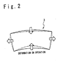
- Fig. 2 is a diagram showing deformation of the side, upper and lower plates of the end portion of the tail pipe section in the operation of the conventional gas turbine combustor as a specific instance.
- a temperature is high on the side of inner wall and is low on the side of the outer wall, of the end portion of the tail pipe through which the burning gas passes in the operation of the gas turbine. Therefore, the side, upper and lower plates of the end portion of the tail pipe section are likely to be deformed to be convex in an inner direction.
- the stiffness of the upper flange 1a and lower flange 1b is remarkably high compared with that of side plates of the side walls 2a and 2b.
- the side plates in the end portion of the tail pipe section are compulsorily deformed in a direction opposite to a direction of original deformation. Therefore, while strong thermal stress generated in the side plates in the end portion of the tail pipe section, and the metal fatigue is accumulated in the side plates in the end portion of the tail pipe section while the gas turbine combustor repeats the start and the stop. Thus, the defect which is based on the metal fatigue in the side wall is caused.
- Combustor and Gas Turbine is disclosed in Japanese Laid open Patent Application ( JP-P2003-322337A ).
- air compressed by a compressor and fuel are mixed and burned.
- Generated burning gas is introduced into a turbine through a burning pipe.
- reinforcement ribs are provided over whole width of a side surface of the burning pipe of an almost rectangular section.
- Gas Turbine Combustor is disclosed in Japanese Laid Open Patent Application ( JP-P2003-193866A ).
- a seal section is made of cobalt alloy having a fatigue resistance coating layer, in which a film of carbide or nitride is formed as a lower layer and an alumina film is used as the uppermost surface film.
- a protection plate of cobalt alloy which contains chrome 15 to 35 weight % and carbon 0.7 to 1.5 weight % for a contact section of the transition piece with the seal section in the engaging portion.
- Gas Turbine Combustor is disclosed in Japanese Laid Open Patent Application ( JP-P2003-185140A ).
- a combustor transition piece tail pipe
- an initial stage stillness wing in the gas turbine for power generation are engaged through a seal section.
- cobalt alloy which contains chrome of 15 to 30 weight% and carbon of 0.05 to 0.25 weight% as a part of the chemical composition is used as a base member.
- a plate to which a coating of chrome carbide of 0.1 to 0.6 mm as a main component is carried out is used as a seal section.
- a cobalt alloy plate is attached to a contact section of the seal section with coating layer in the transition engaging portion.
- An object of the present invention is to provide a gas turbine combustor in which it is possible to intentionally reduce the stiffness of flanges provided for upper and lower walls in a tail pipe section of the gas turbine combustor.
- Another object of the present invention is to provide a gas turbine combustor in which deformation in an end portion of a tail pipe section can be suppressed and high stress generated in a side plate can be suppressed.
- Another object of the present invention is to provide a gas turbine combustor in which fatigue resistance of the combustor is improved.
- a gas turbine combustor of the present invention includes a combustor main body; a tail pipe connected with the combustor main body to spout out burning gas; and a seal section provided to prevent the burning gas from leaking from a space of a plurality of the tail pipes annularly arranged around one axis.
- the tail pipe has upper and lower walls opposite to each other in a radius direction of the axis in an end portion of the tail pipe, and a first engaging portion is provided for the upper and lower walls.
- the seal section has a second engaging portion for engagement with the first engaging portion in a front end of the seal section, The first engaging portion is provided to reduce stiffness of the upper and lower walls,
- the tail pipe further includes side walls opposite to each other in a circumferential direction of the axis in the end portion of the tail pipe.
- the first engaging portion has a structure to reduce a stiffness of the upper and lower walls so as to be substantially equal to a stiffness of the side walls.
- the first engaging portion includes one set of flanges opposite to each other in the radius direction.
- the gas turbine combustor of the present invention may further include a shield plate provided along each of the flanges of the one set.
- the shield plate and the flange may be fixed by a shield plate fixing member, and the tail pipe and the seal section may be connected, by engaging each of the flanges of the one set in which the shield plate is provided, with the second engaging portion.
- the first engaging portion may include one set of flanges provided to oppose to each other in the radius direction and to extend in a flow direction of the burning gas.
- Each of the flanges and the second engaging portion may be engaged with each other in the flow direction of the burning gas.
- each of the flanges may have a convex section
- the second engaging portion may have a concave section which is engaged with the convex section to connect the tail pipe and the seal section.
- the tail pipe may further include a gusset provided on a position apart from the end portion of the tail pipe to extend in a perpendicular direction to a pipe surface of the tail pipe and to fix the tail pipe to a housing of the gas turbine.
- the gusset may have a first supporting section to engage the second engaging portion
- the tail pipe may have a second supporting section provided on the pipe surface of the tail pipe opposite to the gusset to engage the second engaging portion.
- the tail pipe and the seal section may be connected by engaging the first and second supporting sections as the first engaging portion and the second engaging portion.
- the first engaging portion may include the one set of the flanges opposite to each other in the radius direction, and each of the flanges may have an opening.
- a seal plate may be provided along an external circumference of the opening. The external circumference and the seal plate may be welded, and the tail pipe and the seal section may be connected by engaging the one set of the flanges and the seal plate connected to the set and the second engaging portion.
- the first engaging portion may include one set of flanges opposite to each other in the circumferential direction, and each of the flanges may have a slit extending in a' direction perpendicular to the flow direction of the burning gas.
- a gas turbine of the present invention may include the gas turbine combustor according to any of the above.
- a plurality of gas turbine combustors are annularly arranged around one axis.
- a seal section is provided to cover an inner circumferential wall and an outer circumferential wall of an end section (outlet) of a tail pipe section of each of the combustors arranged annually (upper wall and lower wall in the gas turbine combustor).
- a flange is provided for each of the upper and lower walls of the end portion (outlet) of the tail pipe section of each combustor to attach the seal section.
- the stiffness of the flange provided for each of the upper and lower walls of the end portion (outlet) of the tail pipe section is intentionally reduced such that the stiffness of the flange becomes substantially equal to the stiffness of a side plate of each of the side walls.
- Fig. 3A is a diagram schematically showing the structure of the tail pipe section of the gas turbine combustor according to the first embodiment of the present invention when it is seen from the exhaust side in a state of no seal section.
- Fig. 3B is sectional views showing sections of the gas turbine combustor in the first embodiment along the line C-C and the line D-D shown in Fig. 3A.
- a plurality of gas turbine combustors are annularly arranged.
- a seal section is provided to cover each of the upper and lower walls of the end portion (outlet) of the tail pipe section of each combustor so that the burning gas from each combustor can be sealed.
- a plate for each of upper and lower walls of the tail pipe section of the main body 3 of the gas turbine combustor in the present embodiment is provided with an upper seal 20a and a lower seal 20b to connect the plurality of combustors annularly.
- the upper seal 20a and the lower seal 20b are engaged with an upper flange 100a and a lower flange 100b, respectively.
- a gusset 4 is provided on the upper wall of the main body 3 of the combustor tail pipe section to fix the main body 3 of the tail pipe section to the housing of the gas turbine.
- a partition for the adjacent combustors, and side seals 2a and 2b for positioning are arranged for the side walls of the main body 3 of the combustor tail pipe section.
- a positioning pin 5a is inserted in an engaging portion of the upper flange 100a of the main body 3 of the combustor tail pipe section and the upper seal 20a to fix a relative position relation of them.
- a positioning pin 5b is inserted in an engaging portion of the lower flange 100b of the main body 3 of the combustor tail pipe section and the lower seal 20b to fix a relative position relation of them.
- the seal section is connected with an end portion of the main body 3 of the combustor tail pipe section. Also, it is possible to prevent the burning gas from leaking a space between the end portion of the tail pipe section of the combustor main body 3 and the seal sections 20a and 20b.
- the flanges 100a and 100b are provided in which the height is lower than the conventional flanges 1a and 1b (the thickness is made thinner).
- the heights of the seal sections 20a and 20b are reduced suppressed in correspondence to the heights of the flanges 100a and 100b.
- the height of the flange is reduced to a minimum height necessary for the flange and the seal section to engage in a portion other than an engaging portion of the upper flange 100a and the upper seal 20a and an engaging portion of the lower flange 100b and the lower seal 20b, as shown in Fig. 3A.
- the height of each of the flanges which are provided for the upper and lower walls of the end portion (outlet) of the tail pipe section is reduced to a minimum height necessary for the flange and the seal section to engage and to carry out the positioning in a portion other than a positioning portion with the seal section.
- the stiffness of the flange in each of the upper and lower walls in the end portion (outlet) of the tail pipe section of the gas turbine combustor according to the present embodiment can be intentionally reduced.
- the compulsion deformation can be reduced which is caused due to thermal stress generated in the tail pipe section end portion (outlet) on the operation of the gas turbine combustor. Also, it becomes possible to reduce the high stress easy to generate in the side plate.
- the gas turbine combustor having a high fatigue resistance can be realized. Thus, the gas turbine combustor with high reliability can be provided.
- Fig. 4A is a diagram schematically showing the structure of the tail pipe section of the gas turbine combustor according to the second embodiment of the present invention when it is seen from the exhaust side without a seal section.
- Fig. 4B is sectional views showing sections of the tail pipe section of the gas turbine combustor of the second embodiment along the line E-E and the line F-F shown in Fig. 4A.
- the basic components and structure of the gas turbine combustor of the second embodiment are the same as those of the gas turbine combustor of the first embodiment.
- the shapes of an engaging portion of an upper flange 110a and an upper seal 30a and an engaging portion of a lower flange 110b and a lower seal 30b are different from those of the first embodiment.
- the shapes different from the first embodiment and the effect of the shapes will be described.
- the upper seal 30a is inserted into the upper flange 110a and engaged with it
- the lower seal 30b is inserted into the lower flange 110b and engaged with it.
- positioning pins 5a and 5b are inserted in the vertical direction.
- the flanges 110a and 110b and the seal sections 30a and 30b are fixed by these pins, respectively.
- the engaging portion of the upper flange 110a and the upper seal 30a and the engaging portion of the lower flange 110b and the lower seal 30b are formed through the insertion in a horizontal direction. Therefore, the heights of the upper flange 110a and the upper seal 30a and the heights of the lower flange 110b and the lower seal 30b (in a direction perpendicular to the flow direction of burning gas) can be more reduced than the first embodiment.
- the height of the flange provided in each of the upper and lower walls of the end portion (outlet) of the tail pipe section can be suppressed to the minimum height necessary for the flange and the seal section to engage.
- the stiffness of the flange in each of the upper and lower walls of the end portion (outlet) of the tail pipe section can be intentionally reduced. Thus, a stiff difference can be suppressed between the upper and lower walls of the end portion (outlet) of the tail pipe section and the side walls.
- the gas turbine combustor with the high fatigue resistance can be realized and the reliability of the gas turbine combustor improves.
- Fig. 5A is a diagram schematically showing the structure of the tail pipe section of the gas turbine combustor according to the third embodiment of the present invention when it is seen from the exhaust side in a state of no seal section.
- Fig. 5B is sectional views showing sections of the tail pipe section of the gas turbine combustor in the third embodiment along the line I-I and the line J-J shown in Fig. 5A.
- the basic components and structure of the gas turbine combustor according to the present embodiment are the same as those of the gas turbine combustor of the second embodiment.
- the height of an engaging portion of an upper flange 130a and an upper seal 50a and an engaging portion of a lower flange 130b and a lower seal 50b is reduced further lower than in the second embodiment.
- the upper seal 50a is inserted in the upper flange 130a and the lower seal 50b is inserted into the lower flange 130b in the horizontal direction and they are engaged.
- the upper flange 130a is not provided with a comb-shaped gap in the horizontal direction.
- a convex section 135a is engaged with a concave section of the upper seal 50a to connect the upper flange 130a and the upper seal 50a.
- the convex section 135b is engaged with the concave section of the lower seal 50b in the horizontal direction so that the lower flange 130b and the lower seal 50b are connected.
- positioning pins 5a and 5b are inserted in the vertical direction, respectively.
- the flanges 130a and 130b, and the seal sections 50a and 50b are fixed, respectively.
- the heights (thickness) of the upper flange 130a and the upper seal 50a, and the heights of the lower flange 130b and the lower seal 50b (in a direction perpendicular to the flow direction of the burning gas) can be more reduced based on the shape of the engaging portion of the upper flange 130a and the upper seal 50a, and the shape of the engaging portion of the lower flange 130b and the lower seal 50b, compared with the second embodiment.
- the stiffness of the flange in each of the upper and lower walls of the end portion (outlet) of the tail pipe section can be intentionally reduced through the reduction of the height of the flange provided in each of the upper and lower walls of the end portion (outlet) of the tail pipe section.
- the stiffness difference can be reduced between the upper and lower walls of the end portion (outlet) of the tail pipe section and the side walls.
- compulsion deformation can be suppressed which is caused due to the thermal stress generated in the end portion (outlet) of the tail pipe section on the operation of the gas turbine combustor.
- the gas turbine combustor with the high fatigue resistance can be realized and the reliability of the gas turbine combustor improves.
- Fig. 6A is a diagram schematically showing the structure of the tail pipe section of the gas turbine combustor according to the fourth embodiment of the present invention when it is seen from the exhaust side in a state of no seal section.
- Fig. 6B is sectional views showing sections of the tail pipe section of the gas turbine combustor in the fourth embodiment along the line G-G and the line H-H shown in Fig. 6A.
- the basic structure of the gas turbine combustor according to the present embodiment is the same as that of the gas turbine combustor according to the first embodiment. However, in the present embodiment, the gas turbine combustor according to the present embodiment is not provided with the upper flange and the lower flange.
- An upper seal supporting section 120a is provided in a gusset 4 to support the upper seal 40a to be inserted to the end portion (outlet) of the tail pipe section.
- a lower seal supporting section 120b is provided on the surface opposite to the position in which the gusset 4 is provided to insert the lower seal 40b.
- the upper seal 40a is inserted below the upper seal supporting section 120a in the horizontal direction and engaged with it
- the lower seal 40b is inserted below the lower seal supporting section 120b in the horizontal direction and engaged with it.
- positioning pins 5a and 5b are inserted in the vertical direction in suitable portions to fix the supporting sections 120a and 120b and the seal sections 40a and 40b, respectively.
- the seal sections are connected with the main body 3 of the tail pipe section without any flanges on the upper and lower walls of the end portion (outlet) of the tail pipe section, the stiffness difference between the upper and lower walls of the end portion (outlet) of the tail pipe section and the side walls can be greatly reduced.
- the compulsion deformation can be suppressed which is caused due to the thermal stress generated in the end portion (outlet) of the tail pipe section on the operation of the gas turbine combustor.
- the gas turbine combustor with the high fatigue resistance can be realized and the reliability of the gas turbine combustor improves.
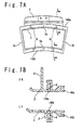
- Fig. 7A is a diagram schematically showing the structure of the tail pipe section of the gas turbine combustor according to the fifth embodiment of the present invention when it is seen from the exhaust side in a state no seal section.
- Fig. 7B is sectional views showing sections of the tail pipe section of the gas turbine combustor of this fifth embodiment along the line K-K and the line L-L shown in Fig. 7A.
- the basic components and structure of the gas turbine combustor in the fifth embodiment are the same as those of the gas turbine combustor of the first embodiment. However, in the present embodiment, slits 6 are provided on optional positions of an upper flange 140a and a lower flange 140b to reduce the stiffness of the flange appropriately.
- slits 6 are provided on optional positions of an upper flange 140a and a lower flange 140b to reduce the stiffness of the flange appropriately.
- an upper seal 60a is inserted into the upper flange 140a in the horizontal direction and engaged with it, ad a lower seal 60b is inserted in the lower flange 140b in the horizontal direction and engaged with it.
- positioning pins 5a and 5b are inserted in suitable positions, to fix the seal sections 60a and 60b and the flanges 140a and 140b, respectively.
- the slits 6 are provided for the upper flange 140a and the lower flange 140b in the vertical direction. The stiffness of each of the flanges 140a and 140b can be reduced by this slit 6.
- the stiffness of the flange in each of the upper and lower walls of the end portion (outlet) of the tail pipe section can be intentionally reduced by the slit 6 provided for the flange in each of the upper and lower walls of the end portion (outlet) of the tail pipe section.
- the stiff difference can be reduced between the upper and lower walls of the end portion (outlet) of the tail pipe section and the side walls.
- the compulsion deformation can be reduced which is caused due to the thermal stress generated in the end portion (outlet) of the tail pipe section on the operation of the gas turbine combustor.
- the gas turbine combustor with the high fatigue resistance can be realized and the reliability of the gas turbine combustor improves.
- Fig. 8A is a diagram schematically showing the structure of the tail pipe section of the gas turbine combustor according to the sixth embodiment of the present invention when it is seen from the exhaust side in a state of no seal section.
- Fig. 8B is sectional views showing sections of the tail pipe section of the gas turbine combustor in the sixth embodiment along the line M-M and the line N-N in Fig. 8A.
- the basic components and structure of the gas turbine combustor according to the present embodiment are the same as those of the gas turbine combustor of the first embodiment.
- openings 7 of appropriate sizes are provided in optional positions of the upper flange 150a and the lower flange 150b.
- a shield plate 9 is provided on a back position of the opening 7 for the purpose to prevent cooling air flowing through the tail pipe main body 3 from leaking through the opening 7.
- the shield plate 9 is welded along the periphery of the opening 7 in the upper flange 150a or the lower flange 150b.
- the upper seal 70a is put on the upper flange 150a in the vertical direction and engaged with it
- the lower seal 70b is put on the lower flange 150b in the vertical direction and engaged with it.
- positioning pins 5a and 5b are inserted in suitable positions in the horizontal direction to fix the flanges 150a and 150b, and the seal sections 70a and 70b, respectively.
- the openings 7 are provided for the upper flange 150a and the lower flange 150b. The stiffness of each of the flanges 150a and 150b formed in the upper and lower walls of the end portion (outlet) of the tail pipe section can be reduced with this opening 7.
- a warp of the side wall can be reduced which is caused due to the thermal stress generated due to the stiff difference between the upper and lower walls of the end portion (outlet) of the tail pipe section and the side walls on the operation of the gas turbine combustor of the present embodiment.
- the shield plate 9 is provided on the back of the opening 7, it is possible to prevent cooling air flowing through the main body 3 of the tail pipe section from leaking from the opening 7, and the improvement of the reliability is attained at a same time.
- the stiffness of the flange in each of the upper and lower walls of the end portion (outlet) of the tail pipe section can be intentionally reduced with the opening 7 provided for each of the upper and lower walls of the end portion (outlet) of the tail pipe section.
- the stiff difference can be reduced between the upper and lower walls of the end portion (outlet) of the tail pipe section and the side wall.
- the compulsion deformation can be reduced which is caused due to the thermal stress generated in the end portion (outlet) of the tail pipe section on the operation of the gas turbine combustor.
- the high stress easy to generate in the side plate can be reduced.
- the gas turbine combustor with the high fatigue resistance can be realized and the reliability of the gas turbine combustor can be improved.
- Fig. 9A is a diagram schematically showing the structure of the tail pipe section of the gas turbine combustor according to the seventh embodiment of the present invention when it is seen from the exhaust side in a state of no seal section.
- Fig. 9B is sectional views showing sections of the tail pipe section of the gas turbine combustor in the seventh embodiment along the line O-O and the line P-P shown in Fig. 9A.
- the basic components and structure of the gas turbine combustor of the seventh embodiment are the same as those of the gas turbine combustor of the first embodiment.
- a shield plate 9 for seal is provided along each of the upper flange 160a and the lower flange 160b, for the purpose to prevent the burning gas from leaking from a flow path.
- the upper flange 160a and the lower flange 160b and the shield plate 9 are fixed by positioning pins 55, respectively.
- the upper seal 80a is pushed to the upper flange 160a in the vertical direction and engaged with it, and the lower seal 80b is pushed to the lower flange 160b in the vertical direction and engaged with it.
- the positioning pins 5a and 5b are inserted in suitable positions, to fix the flanges 160a and 160b, and the seal sections 80a and 80b.
- the heights (the length in the perpendicular direction to the flow direction of the burning gas) of the upper flange 160a and the lower flange 160b are set low.
- the stiffness of the upper and lower walls of the end portion (outlet) of the tail pipe section can be reduced.
- a warp of the side wall can be reduced which is caused due to the thermal stress generated due to the stiffness difference between the upper and lower walls of the end portion (outlet) of the tail pipe section and the side wall on the operation of the gas turbine combustor of the present embodiment.
- the shield plate 9 is arranged along each of the flanges 160a and 160b. Therefore, it is possible to prevent the burning gas from leaking from gaps between the flanges 160a and 160b, and the seal sections 80a and 80b, and the improvement of the reliability is attained at a same time.
- the gas turbine combustor with the high fatigue resistance can be realized and the reliability of the gas turbine combustor improves.
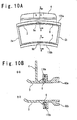
- Fig. 10A is a diagram schematically showing the structure of the tail pipe section of the gas turbine combustor according to the eighth embodiment of the present invention when it is seen from the exhaust side in a state of no seal section.
- Fig. 10B is sectional views showing sections of the tail pipe section of the gas turbine combustor in the eighth embodiment along the line Q-Q and the line R-R shown in Fig. 10A.
- the basic components and structure of the gas turbine combustor according to the present embodiment are the same as those of the gas turbine combustor of the first embodiment.
- the rear ends of the upper flange 170a and lower flange 170b of the present embodiment are provided with the slits 6 extending in the horizontal direction, respectively.
- the upper flange 170a and the lower flange 170b are engaged with the upper seal 90a and the lower seal 90b, respectively. Then, by inserting positioning pins 5a and 5b into suitable positions in the horizontal direction, the flanges 170a and 170b, and the seal sections 90a and 90b are fixed, respectively.
- the slits extending in the horizontal direction are provided in the rear ends of the upper flange 170a and lower flange 170b.
- a warp of the side wall can be reduced which is caused due to the thermal stress generated due to the stiff difference between the upper and lower walls of the end portion (outlet) of the tail pipe section and the side wall on the operation of the gas turbine combustor of the present embodiment.
- the gas turbine combustor with the high fatigue resistance can be realized and the reliability of the gas turbine combustor improves.
- the gas turbine combustor can be provided in which the fatigue resistance of the combustor is improved.
Landscapes
- Engineering & Computer Science (AREA)
- Mechanical Engineering (AREA)
- General Engineering & Computer Science (AREA)
- Chemical & Material Sciences (AREA)
- Combustion & Propulsion (AREA)
- Turbine Rotor Nozzle Sealing (AREA)
Abstract
Description
- The present invention relates to a gas turbine combustor.
- Fig. 1A is a diagram schematically showing the structure of a tail pipe section of a conventional combustor seen from an exhaust side of burning gas. Also, Fig. 1B is sectional views showing sections of the tail pipe section of the conventional combustor along the lines A-A and B-B shown in Fig. 1A. As shown in Fig, 1A, when a plurality of combustors are annularly provided with around one axis, an
upper flange 1a and alower flange 1b are provided for an end portion of amain body 3 of the tail pipe section to fix anupper seal section 10a and alower seal section 10b so that the burning gas can be prevented from leaking from a gap between adjacent tail pipes. Also, agusset 4 is provided for an upper portion of themain body 3 of the tail pipe section to fix themain body 3 of the tail pipe on the housing of the gas turbine. Also,side seals main body 3 of the combustor tail pipe section to function as a partition of the adjacent combustors. As shown in Fig. 1B, theupper seal section 10a and thelower seal section 10b are engaged with theupper flange 1a and thelower flange 1b in themain body 3 of the combustor tail pipe section, respectively. Apositioning pin 5a is inserted in an engaging portion of theupper flange 1a of themain body 3 of the combustor tail pipe section and theupper seal section 10a to fix a relative position of them. In the same way, apositioning pin 5b is inserted in an engaging portion of thelower flange 1b of themain body 3 of the combustor tail pipe section and thelower seal section 10b to fix a relative position of them. In this way, theseal sections main body 3 of the tail pipe section and the leakage of burning gas from the gaps between the end portion of themain body 3 of the combustor tail pipe section and the seal sections is prevented. - In the conventional gas turbine combustor, there is a case that defects such as thermal deformation is caused due to low cycle fatigue in the end portion (outlet) of the combustor tail pipe section during a burning operation. Since the thicknesses of structural plates are different between the side walls and the upper and lower walls in the end portion of the combustor tail pipe section so that the stiffness of the plate in the upper and lower walls thicker than the side walls is high, the low cycle fatigue is caused when thermal stress is impressed on the end portion of the combustor tail pipe section so that compulsory thermal deformation is caused in a plate of the side wall while a start and a stop of the operation of the gas turbine combustor are repeated. Therefore, while the gas turbine combustor repeats the start and the stop, the metal fatigue due to the thermal deformation is accumulated and a warp is generated in the plate of the side wall to form crack.
- Fig. 2 is a diagram showing deformation of the side, upper and lower plates of the end portion of the tail pipe section in the operation of the conventional gas turbine combustor as a specific instance. A temperature is high on the side of inner wall and is low on the side of the outer wall, of the end portion of the tail pipe through which the burning gas passes in the operation of the gas turbine. Therefore, the side, upper and lower plates of the end portion of the tail pipe section are likely to be deformed to be convex in an inner direction. However, the stiffness of the
upper flange 1a andlower flange 1b is remarkably high compared with that of side plates of theside walls - In conjunction with "Combustor and Gas Turbine" is disclosed in the Japanese Laid Open Patent Application (
JP-P2004-84601A - Also, "Combustor and Gas Turbine" is disclosed in Japanese Laid open Patent Application (
JP-P2003-322337A - Also, "Gas Turbine Combustor" is disclosed in Japanese Laid Open Patent Application (
JP-P2003-193866A - Also, "Gas Turbine Combustor" is disclosed in Japanese Laid Open Patent Application (
JP-P2003-185140A - An object of the present invention is to provide a gas turbine combustor in which it is possible to intentionally reduce the stiffness of flanges provided for upper and lower walls in a tail pipe section of the gas turbine combustor.
- Another object of the present invention is to provide a gas turbine combustor in which deformation in an end portion of a tail pipe section can be suppressed and high stress generated in a side plate can be suppressed.
- Another object of the present invention is to provide a gas turbine combustor in which fatigue resistance of the combustor is improved.
- A gas turbine combustor of the present invention includes a combustor main body; a tail pipe connected with the combustor main body to spout out burning gas; and a seal section provided to prevent the burning gas from leaking from a space of a plurality of the tail pipes annularly arranged around one axis. The tail pipe has upper and lower walls opposite to each other in a radius direction of the axis in an end portion of the tail pipe, and a first engaging portion is provided for the upper and lower walls. The seal section has a second engaging portion for engagement with the first engaging portion in a front end of the seal section, The first engaging portion is provided to reduce stiffness of the upper and lower walls,
- In the gas turbine combustor of the present invention, the tail pipe further includes side walls opposite to each other in a circumferential direction of the axis in the end portion of the tail pipe. The first engaging portion has a structure to reduce a stiffness of the upper and lower walls so as to be substantially equal to a stiffness of the side walls.
- Also, in the gas turbine combustor of the present invention, the first engaging portion includes one set of flanges opposite to each other in the radius direction. In this case, the gas turbine combustor of the present invention may further include a shield plate provided along each of the flanges of the one set. The shield plate and the flange may be fixed by a shield plate fixing member, and the tail pipe and the seal section may be connected, by engaging each of the flanges of the one set in which the shield plate is provided, with the second engaging portion.
- Also, in the gas turbine combustor of the present invention, the first engaging portion may include one set of flanges provided to oppose to each other in the radius direction and to extend in a flow direction of the burning gas. Each of the flanges and the second engaging portion may be engaged with each other in the flow direction of the burning gas. In this case, each of the flanges may have a convex section, and the second engaging portion may have a concave section which is engaged with the convex section to connect the tail pipe and the seal section.
- Also, in the gas turbine combustor of the present invention; the tail pipe may further include a gusset provided on a position apart from the end portion of the tail pipe to extend in a perpendicular direction to a pipe surface of the tail pipe and to fix the tail pipe to a housing of the gas turbine. The gusset may have a first supporting section to engage the second engaging portion, the tail pipe may have a second supporting section provided on the pipe surface of the tail pipe opposite to the gusset to engage the second engaging portion. The tail pipe and the seal section may be connected by engaging the first and second supporting sections as the first engaging portion and the second engaging portion.
- Also, in the gas turbine combustor of the present invention, the first engaging portion may include the one set of the flanges opposite to each other in the radius direction, and each of the flanges may have an opening. In this case, a seal plate may be provided along an external circumference of the opening. The external circumference and the seal plate may be welded, and the tail pipe and the seal section may be connected by engaging the one set of the flanges and the seal plate connected to the set and the second engaging portion.
- Also, in the gas turbine combustor of the present invention, the first engaging portion may include one set of flanges opposite to each other in the circumferential direction, and each of the flanges may have a slit extending in a' direction perpendicular to the flow direction of the burning gas.
- A gas turbine of the present invention may include the gas turbine combustor according to any of the above.
-
- Fig. 1A is a diagram schematically showing the structure of a conventional combustor tail pipe section, and Fig. 1B is sectional views showing sections of the conventional combustor tail pipe section along the line A-A and the line B-B shown in Fig. 1A;
- Fig. 2 is a diagram showing deformation of the side, upper and lower walls of an end portion of the tail pipe section in the conventional gas turbine combustor;
- Fig. 3A is a diagram schematically showing the structure of a tail pipe section of a gas turbine combustor according to a first embodiment of the present invention when it is seen from an exhaust side in a state of no seal section, and Fig. 3B is sectional views showing sections of the gas turbine combustor in the first embodiment along the line c-c and the line D-D shown in Fig. 3A;
- Fig. 4A is a diagram schematically showing the structure of the tail pipe section of the gas turbine combustor according to a second embodiment of the present invention when it is seen from the exhaust side in a state of no seal section, and Fig. 4B is sectional views showing sections of the gas turbine combustor in the second embodiment along the line E-E and the line F-F shown in Fig. 4A;
- Fig. 5A is a diagram schematically showing the structure of the tail pipe section of the gas turbine combustor according to a third embodiment of the present invention when it is seen from the exhaust side in a state of no seal section, and Fig. 5B is sectional views showing sections of the gas turbine combustor in the third embodiment along the line E-E and the line F-F shown in Fig. 5A;
- Fig. 6A is a diagram schematically showing the structure of the tail pipe section of the gas turbine combustor according to a fourth embodiment of the present invention when it is seen from the exhaust side in a state of no seal section, and Fig. 6B is sectional views showing sections of the gas turbine combustor in the fourth embodiment along the line G-G and the line H-H shown in Fig. 6A;
- Fig. 7A is a diagram schematically showing the structure of the tail pipe section of the gas turbine combustor according to a fifth embodiment of the present invention when it is seen from the exhaust side in a state of no seal section, and Fig. 7B is sectional views showing sections of the gas turbine combustor in the fifth embodiment along the line K-K and the line L-L shown in Fig. 7A;
- Fig. 8A is a diagram schematically showing the structure of the tail pipe section of the gas turbine combustor according to a sixth embodiment of the present invention when it is seen from the exhaust side in a state of no seal section, and Fig. 8B is sectional views showing sections of the gas turbine combustor in the sixth embodiment along the line M-M and the line N-N shown in Fig. 8A;
- Fig. 9A is a diagram schematically showing the structure of the tail pipe section of the gas turbine combustor according to a seventh embodiment of the present invention when it is seen from the exhaust side in a state of no seal section, and Fig. 9B is sectional views showing sections of the gas turbine combustor in the seventh embodiment along the line O-O and the line P-P shown in Fig. 9A; and
- Fig. 10A is a diagram schematically showing the structure of the tail pipe section of the gas turbine combustor according to an eighth embodiment of the present invention when it is seen from the exhaust side in a state of no seal section, and Fig. 10B is sectional views showing sections of the gas turbine combustor in the eighth embodiment along the line Q-Q and the line R-R shown in Fig. 10A.
- Hereinafter, a gas turbine combustor of the present invention will be described in detail with the reference to the attached drawings.
- In the gas turbine, a plurality of gas turbine combustors are annularly arranged around one axis. In order to prevent burning gas from leaking from each gas turbine combustor, a seal section is provided to cover an inner circumferential wall and an outer circumferential wall of an end section (outlet) of a tail pipe section of each of the combustors arranged annually (upper wall and lower wall in the gas turbine combustor). For this purpose, a flange is provided for each of the upper and lower walls of the end portion (outlet) of the tail pipe section of each combustor to attach the seal section.
- In the gas turbine combustor of the present invention, the stiffness of the flange provided for each of the upper and lower walls of the end portion (outlet) of the tail pipe section is intentionally reduced such that the stiffness of the flange becomes substantially equal to the stiffness of a side plate of each of the side walls. Thus, compulsion deformation is suppressed which is caused due to thermal stress generated in the end portion (outlet) of the tail pipe section on the operation of the conventional gas turbine combustor, and it becomes possible to reduce high stress easy to generate in the side plate. As a result, the high fatigue resistance gas turbine combustor can be realized.
- Fig. 3A is a diagram schematically showing the structure of the tail pipe section of the gas turbine combustor according to the first embodiment of the present invention when it is seen from the exhaust side in a state of no seal section. Also, Fig. 3B is sectional views showing sections of the gas turbine combustor in the first embodiment along the line C-C and the line D-D shown in Fig. 3A.
- In the gas turbine combustor of the present invention, a plurality of gas turbine combustors are annularly arranged. A seal section is provided to cover each of the upper and lower walls of the end portion (outlet) of the tail pipe section of each combustor so that the burning gas from each combustor can be sealed. For this purpose, as Fig. 3B, a plate for each of upper and lower walls of the tail pipe section of the
main body 3 of the gas turbine combustor in the present embodiment is provided with anupper seal 20a and alower seal 20b to connect the plurality of combustors annularly. Theupper seal 20a and thelower seal 20b are engaged with anupper flange 100a and alower flange 100b, respectively. Also, agusset 4 is provided on the upper wall of themain body 3 of the combustor tail pipe section to fix themain body 3 of the tail pipe section to the housing of the gas turbine. A partition for the adjacent combustors, andside seals main body 3 of the combustor tail pipe section. Apositioning pin 5a is inserted in an engaging portion of theupper flange 100a of themain body 3 of the combustor tail pipe section and theupper seal 20a to fix a relative position relation of them. In the same way, apositioning pin 5b is inserted in an engaging portion of thelower flange 100b of themain body 3 of the combustor tail pipe section and thelower seal 20b to fix a relative position relation of them. In this way, the seal section is connected with an end portion of themain body 3 of the combustor tail pipe section. Also, it is possible to prevent the burning gas from leaking a space between the end portion of the tail pipe section of the combustormain body 3 and theseal sections - In the present embodiment, as shown in Fig. 3B, the
flanges conventional flanges seal sections flanges upper flange 100a and theupper seal 20a and an engaging portion of thelower flange 100b and thelower seal 20b, as shown in Fig. 3A. - In the gas turbine combustor according to the present embodiment, the height of each of the flanges which are provided for the upper and lower walls of the end portion (outlet) of the tail pipe section is reduced to a minimum height necessary for the flange and the seal section to engage and to carry out the positioning in a portion other than a positioning portion with the seal section. Thus, the stiffness of the flange in each of the upper and lower walls in the end portion (outlet) of the tail pipe section of the gas turbine combustor according to the present embodiment can be intentionally reduced. Thus, it is possible to reduce the stiff difference between the upper and lower walls and the side walls in the tail pipe section end section (outlet). The compulsion deformation can be reduced which is caused due to thermal stress generated in the tail pipe section end portion (outlet) on the operation of the gas turbine combustor. Also, it becomes possible to reduce the high stress easy to generate in the side plate. In the present embodiment, the gas turbine combustor having a high fatigue resistance can be realized. Thus, the gas turbine combustor with high reliability can be provided.
- Fig. 4A is a diagram schematically showing the structure of the tail pipe section of the gas turbine combustor according to the second embodiment of the present invention when it is seen from the exhaust side without a seal section. Also, Fig. 4B is sectional views showing sections of the tail pipe section of the gas turbine combustor of the second embodiment along the line E-E and the line F-F shown in Fig. 4A.
- The basic components and structure of the gas turbine combustor of the second embodiment are the same as those of the gas turbine combustor of the first embodiment. However, in the second embodiment, the shapes of an engaging portion of an
upper flange 110a and anupper seal 30a and an engaging portion of alower flange 110b and alower seal 30b are different from those of the first embodiment. The shapes different from the first embodiment and the effect of the shapes will be described. - In the second embodiment, as shown in Fig. 4B, the
upper seal 30a is inserted into theupper flange 110a and engaged with it, and thelower seal 30b is inserted into thelower flange 110b and engaged with it. After the engagement, in suitable portions, positioning pins 5a and 5b are inserted in the vertical direction. Theflanges seal sections upper flange 110a and theupper seal 30a and the engaging portion of thelower flange 110b and thelower seal 30b are formed through the insertion in a horizontal direction. Therefore, the heights of theupper flange 110a and theupper seal 30a and the heights of thelower flange 110b and thelower seal 30b (in a direction perpendicular to the flow direction of burning gas) can be more reduced than the first embodiment. - In the gas turbine combustor according to the present embodiment, the height of the flange provided in each of the upper and lower walls of the end portion (outlet) of the tail pipe section can be suppressed to the minimum height necessary for the flange and the seal section to engage. The stiffness of the flange in each of the upper and lower walls of the end portion (outlet) of the tail pipe section can be intentionally reduced. Thus, a stiff difference can be suppressed between the upper and lower walls of the end portion (outlet) of the tail pipe section and the side walls. As a result, the compulsion deformation caused due to the thermal stress generated in the end portion (outlet) of the tail pipe section on the operation of the gas turbine combustor, and it becomes possible to reduce the high stress easy to generate in the side plate. In the present embodiment, the gas turbine combustor with the high fatigue resistance can be realized and the reliability of the gas turbine combustor improves.
- Fig. 5A is a diagram schematically showing the structure of the tail pipe section of the gas turbine combustor according to the third embodiment of the present invention when it is seen from the exhaust side in a state of no seal section. Also, Fig. 5B is sectional views showing sections of the tail pipe section of the gas turbine combustor in the third embodiment along the line I-I and the line J-J shown in Fig. 5A. The basic components and structure of the gas turbine combustor according to the present embodiment are the same as those of the gas turbine combustor of the second embodiment. However, in the present embodiment, the height of an engaging portion of an
upper flange 130a and anupper seal 50a and an engaging portion of alower flange 130b and alower seal 50b is reduced further lower than in the second embodiment. The shapes different from the second embodiment and the effect of the shapes below will be described. - As shown in Fig. 5B in the present embodiment, the
upper seal 50a is inserted in theupper flange 130a and thelower seal 50b is inserted into thelower flange 130b in the horizontal direction and they are engaged. - In the present embodiment, the
upper flange 130a is not provided with a comb-shaped gap in the horizontal direction. Aconvex section 135a is engaged with a concave section of theupper seal 50a to connect theupper flange 130a and theupper seal 50a. In the same manner, in the connection of thelower flange 130b and thelower seal 50b, theconvex section 135b is engaged with the concave section of thelower seal 50b in the horizontal direction so that thelower flange 130b and thelower seal 50b are connected. After the engagement, positioning pins 5a and 5b are inserted in the vertical direction, respectively. Thus, theflanges seal sections upper flange 130a and theupper seal 50a, and the heights of thelower flange 130b and thelower seal 50b (in a direction perpendicular to the flow direction of the burning gas) can be more reduced based on the shape of the engaging portion of theupper flange 130a and theupper seal 50a, and the shape of the engaging portion of thelower flange 130b and thelower seal 50b, compared with the second embodiment. - In the gas turbine combustor according to the present embodiment, the stiffness of the flange in each of the upper and lower walls of the end portion (outlet) of the tail pipe section can be intentionally reduced through the reduction of the height of the flange provided in each of the upper and lower walls of the end portion (outlet) of the tail pipe section. Thus, the stiffness difference can be reduced between the upper and lower walls of the end portion (outlet) of the tail pipe section and the side walls. Also, compulsion deformation can be suppressed which is caused due to the thermal stress generated in the end portion (outlet) of the tail pipe section on the operation of the gas turbine combustor. Also, it becomes possible to reduce the high stress easy to generate in the side plate. In the present embodiment, the gas turbine combustor with the high fatigue resistance can be realized and the reliability of the gas turbine combustor improves.
- Fig. 6A is a diagram schematically showing the structure of the tail pipe section of the gas turbine combustor according to the fourth embodiment of the present invention when it is seen from the exhaust side in a state of no seal section. Also, Fig. 6B is sectional views showing sections of the tail pipe section of the gas turbine combustor in the fourth embodiment along the line G-G and the line H-H shown in Fig. 6A.
- The basic structure of the gas turbine combustor according to the present embodiment is the same as that of the gas turbine combustor according to the first embodiment. However, in the present embodiment, the gas turbine combustor according to the present embodiment is not provided with the upper flange and the lower flange. An upper
seal supporting section 120a is provided in agusset 4 to support theupper seal 40a to be inserted to the end portion (outlet) of the tail pipe section. A lowerseal supporting section 120b is provided on the surface opposite to the position in which thegusset 4 is provided to insert thelower seal 40b. - In the present embodiment, as shown in Fig. 6B, the
upper seal 40a is inserted below the upperseal supporting section 120a in the horizontal direction and engaged with it, and thelower seal 40b is inserted below the lowerseal supporting section 120b in the horizontal direction and engaged with it. After the engagement, positioning pins 5a and 5b are inserted in the vertical direction in suitable portions to fix the supportingsections seal sections - In the present embodiment, since the seal sections are connected with the
main body 3 of the tail pipe section without any flanges on the upper and lower walls of the end portion (outlet) of the tail pipe section, the stiffness difference between the upper and lower walls of the end portion (outlet) of the tail pipe section and the side walls can be greatly reduced. Thus, the compulsion deformation can be suppressed which is caused due to the thermal stress generated in the end portion (outlet) of the tail pipe section on the operation of the gas turbine combustor. Also, it becomes possible to reduce the high stress easy to generate in the side plate. In the present embodiment, the gas turbine combustor with the high fatigue resistance can be realized and the reliability of the gas turbine combustor improves. - Fig. 7A is a diagram schematically showing the structure of the tail pipe section of the gas turbine combustor according to the fifth embodiment of the present invention when it is seen from the exhaust side in a state no seal section. Also, Fig. 7B is sectional views showing sections of the tail pipe section of the gas turbine combustor of this fifth embodiment along the line K-K and the line L-L shown in Fig. 7A.
- The basic components and structure of the gas turbine combustor in the fifth embodiment are the same as those of the gas turbine combustor of the first embodiment. However, in the present embodiment, slits 6 are provided on optional positions of an
upper flange 140a and alower flange 140b to reduce the stiffness of the flange appropriately. The shapes of components different from those of the first embodiment and the effect of the shapes will be described below. - In the present embodiment, as shown in Fig. 7B, an
upper seal 60a is inserted into theupper flange 140a in the horizontal direction and engaged with it, ad alower seal 60b is inserted in thelower flange 140b in the horizontal direction and engaged with it. After the engagement, positioning pins 5a and 5b are inserted in suitable positions, to fix theseal sections flanges slits 6 are provided for theupper flange 140a and thelower flange 140b in the vertical direction. The stiffness of each of theflanges slit 6. As a result, a warp of the side wall can be reduced which is caused due to the thermal stress generated due to the stiff difference between the upper and lower walls of the end portion (outlet) of the tail pipe section and the side walls on the operation of the gas turbine combustor of the present embodiment. - In the gas turbine combustor according to the present embodiment, the stiffness of the flange in each of the upper and lower walls of the end portion (outlet) of the tail pipe section can be intentionally reduced by the
slit 6 provided for the flange in each of the upper and lower walls of the end portion (outlet) of the tail pipe section. Thus, the stiff difference can be reduced between the upper and lower walls of the end portion (outlet) of the tail pipe section and the side walls. Also, the compulsion deformation can be reduced which is caused due to the thermal stress generated in the end portion (outlet) of the tail pipe section on the operation of the gas turbine combustor. Also, it becomes possible to reduce the high stress easy to generate in the side plate. In the present embodiment, the gas turbine combustor with the high fatigue resistance can be realized and the reliability of the gas turbine combustor improves. - Fig. 8A is a diagram schematically showing the structure of the tail pipe section of the gas turbine combustor according to the sixth embodiment of the present invention when it is seen from the exhaust side in a state of no seal section. Also, Fig. 8B is sectional views showing sections of the tail pipe section of the gas turbine combustor in the sixth embodiment along the line M-M and the line N-N in Fig. 8A.
- The basic components and structure of the gas turbine combustor according to the present embodiment are the same as those of the gas turbine combustor of the first embodiment. However, in the present embodiment, openings 7 of appropriate sizes are provided in optional positions of the
upper flange 150a and thelower flange 150b. When theupper flange 150a and the seal section are engaged and thelower flange 150b and the seal section are engaged, ashield plate 9 is provided on a back position of the opening 7 for the purpose to prevent cooling air flowing through the tail pipemain body 3 from leaking through the opening 7. Theshield plate 9 is welded along the periphery of the opening 7 in theupper flange 150a or thelower flange 150b. - In the present embodiment, as shown in Fig. 8B, the
upper seal 70a is put on theupper flange 150a in the vertical direction and engaged with it, and thelower seal 70b is put on thelower flange 150b in the vertical direction and engaged with it. After the engagement, positioning pins 5a and 5b are inserted in suitable positions in the horizontal direction to fix theflanges seal sections upper flange 150a and thelower flange 150b. The stiffness of each of theflanges - In the present embodiment, since the
shield plate 9 is provided on the back of the opening 7, it is possible to prevent cooling air flowing through themain body 3 of the tail pipe section from leaking from the opening 7, and the improvement of the reliability is attained at a same time. - In the gas turbine combustor according to the present embodiment, the stiffness of the flange in each of the upper and lower walls of the end portion (outlet) of the tail pipe section can be intentionally reduced with the opening 7 provided for each of the upper and lower walls of the end portion (outlet) of the tail pipe section. Thus, the stiff difference can be reduced between the upper and lower walls of the end portion (outlet) of the tail pipe section and the side wall. Also, the compulsion deformation can be reduced which is caused due to the thermal stress generated in the end portion (outlet) of the tail pipe section on the operation of the gas turbine combustor. The high stress easy to generate in the side plate can be reduced. In the present embodiment, the gas turbine combustor with the high fatigue resistance can be realized and the reliability of the gas turbine combustor can be improved.
- Fig. 9A is a diagram schematically showing the structure of the tail pipe section of the gas turbine combustor according to the seventh embodiment of the present invention when it is seen from the exhaust side in a state of no seal section. Also, Fig. 9B is sectional views showing sections of the tail pipe section of the gas turbine combustor in the seventh embodiment along the line O-O and the line P-P shown in Fig. 9A.
- The basic components and structure of the gas turbine combustor of the seventh embodiment are the same as those of the gas turbine combustor of the first embodiment. However, in the present embodiment, when the
flanges seal sections shield plate 9 for seal is provided along each of theupper flange 160a and thelower flange 160b, for the purpose to prevent the burning gas from leaking from a flow path. Also, theupper flange 160a and thelower flange 160b and theshield plate 9 are fixed by positioningpins 55, respectively. - In the present embodiment, as shown in Fig. 9B, the
upper seal 80a is pushed to theupper flange 160a in the vertical direction and engaged with it, and thelower seal 80b is pushed to thelower flange 160b in the vertical direction and engaged with it. After the engagement, the positioning pins 5a and 5b are inserted in suitable positions, to fix theflanges seal sections - In the present embodiment, like the first embodiment, the heights (the length in the perpendicular direction to the flow direction of the burning gas) of the
upper flange 160a and thelower flange 160b are set low. Thus, the stiffness of the upper and lower walls of the end portion (outlet) of the tail pipe section can be reduced. Also, a warp of the side wall can be reduced which is caused due to the thermal stress generated due to the stiffness difference between the upper and lower walls of the end portion (outlet) of the tail pipe section and the side wall on the operation of the gas turbine combustor of the present embodiment. - Moreover, in the present embodiment, the
shield plate 9 is arranged along each of theflanges flanges seal sections - Fig. 10A is a diagram schematically showing the structure of the tail pipe section of the gas turbine combustor according to the eighth embodiment of the present invention when it is seen from the exhaust side in a state of no seal section. Also, Fig. 10B is sectional views showing sections of the tail pipe section of the gas turbine combustor in the eighth embodiment along the line Q-Q and the line R-R shown in Fig. 10A.
- The basic components and structure of the gas turbine combustor according to the present embodiment are the same as those of the gas turbine combustor of the first embodiment. However, the rear ends of the
upper flange 170a andlower flange 170b of the present embodiment are provided with theslits 6 extending in the horizontal direction, respectively. In the present embodiment, theupper flange 170a and thelower flange 170b are engaged with theupper seal 90a and thelower seal 90b, respectively. Then, by insertingpositioning pins flanges seal sections - In the present embodiment, the slits extending in the horizontal direction (the flow direction of burning gas) are provided in the rear ends of the
upper flange 170a andlower flange 170b. Thus, thermal expansion deformation caused in the upper and lower walls of the end portion (outlet) of the tail pipe section on the operation of the gas turbine combustor operation is absorbed by theslit 6 and is cancelled by this. Thereby, the stiffness of the flange in each of the upper and lower walls of the end portion (outlet) of the tail pipe section is reduced. Also, a warp of the side wall can be reduced which is caused due to the thermal stress generated due to the stiff difference between the upper and lower walls of the end portion (outlet) of the tail pipe section and the side wall on the operation of the gas turbine combustor of the present embodiment. In the present embodiment, the gas turbine combustor with the high fatigue resistance can be realized and the reliability of the gas turbine combustor improves. - According to the present invention, by reducing the stiffness of the flange provided for the upper and lower walls of the end portion (outlet) of the tail pipe section in the gas turbine combustor intentionally, it is possible to reduces the compulsion deformation of the side plates of the tail pipe section, and it is possible to reduce high stress generated in the side plate, Thus, the gas turbine combustor can be provided in which the fatigue resistance of the combustor is improved.
Claims (12)
- A gas turbine combustor comprising:a combustor main body;a tail pipe connected with said combustor main body to spout out burning gas; anda seal section provided to prevent said burning gas from leaking from a space of a plurality of said tailpipes annularly arranged around one axis,wherein said tail pipe has upper and lower walls opposite to each other in a radius direction of said axis in a end portion of said tail pipe, and a first engaging portion is provided for said upper and lower walls,said seal section has a second engaging portion for engagement with said first engaging portion in a front end of said seal section, andsaid first engaging portion is provided to reduce stiffness of said upper and lower walls.
- The gas turbine combustor according to claim 1, wherein said tail pipe further comprises:side walls opposite to each other in a circumferential direction of said axis in the end portion of said tail pipe, andsaid first engaging portion has a structure to reduce a stiffness of said upper and lower walls so as to be substantially equal to a stiffness of said side walls.
- The gas turbine combustor according to claim 1 or 2, wherein said first engaging portion comprises one set of flanges opposite to each other in the radius direction.
- The gas turbine combustor according to claim 3, further comprising:a shield plate provided along each of said flanges of the one set,wherein said shield plate and said flange are fixed by a shield plate fixing member, andsaid tail pipe and said seal section are connected, by engaging each of said flanges of the one set in which said shield plate is provided, with said second engaging portion.
- The gas turbine combustor according to claim 1 or 2, wherein said first engaging portion comprises one set of flanges provided to oppose to each other in said radius direction and to extend in a flow direction of said burning gas, and
each of said flanges and said second engaging portion are engaged with each other in the flow direction of said burning gas. - The gas turbine combustor according to claim 5, wherein each of said flanges has a convex section, and
said second engaging portion has a concave section which is engaged with said convex section to connect said tail pipe and said seal section. - The gas turbine combustor according to claim 1 or 2, wherein said tail pipe further comprises:a gusset provided on a position apart from the end portion of said tail pipe to extend in a perpendicular direction to a pipe surface of said tail pipe and to fix said tail pipe to a housing of the gas turbine,said gusset has a first supporting section to engage said second engaging portion,said tail pipe has a second supporting section provided on the pipe surface of said tail pipe opposite to said gusset to engage said second engaging portion, andsaid tail pipe and said seal section are connected by engaging said first and second supporting sections as first engaging portion and said second engaging portion.
- The gas turbine combustor according to claim 1 or 2, wherein said first engaging portion comprises:said one set of said flanges opposite to each other in the radius direction, andeach of said flanges has an opening.
- The gas turbine combustor according to claim 8, wherein a seal plate is provided along an external circumference of said opening,
said external circumference and said seal plate are welded, and
said tail pipe and said seal section are connected by engaging said one set of said flanges and said seal plate connected to said set and said second engaging portion. - The gas turbine combustor according to claim 1 or 2, wherein said first engaging portion comprises one set of flanges opposite to each other in the circumferential direction, and
each of said flanges has a slit extending in a direction perpendicular to the flow direction of said burning gas. - The gas turbine combustor according to claim 1 or 2, wherein said first engaging portion comprises one set of flanges opposite to each other in the circumferential direction, and
each of said flanges has a slit extending in the flow direction of said burning gas. - A gas turbine comprising said gas turbine combustor according to any of claims 1 to 11.
Applications Claiming Priority (2)
| Application Number | Priority Date | Filing Date | Title |
|---|---|---|---|
| JP2005106811A JP4476152B2 (en) | 2005-04-01 | 2005-04-01 | Gas turbine combustor |
| PCT/JP2006/305449 WO2006109431A1 (en) | 2005-04-01 | 2006-03-17 | Gas turbine combustor |
Publications (2)
| Publication Number | Publication Date |
|---|---|
| EP1865262A1 true EP1865262A1 (en) | 2007-12-12 |
| EP1865262A4 EP1865262A4 (en) | 2014-08-06 |
Family
ID=37086722
Family Applications (1)
| Application Number | Title | Priority Date | Filing Date |
|---|---|---|---|
| EP06729438.9A Withdrawn EP1865262A4 (en) | 2005-04-01 | 2006-03-17 | COMBUSTION CHAMBER FOR GAS TURBINE |
Country Status (5)
| Country | Link |
|---|---|
| US (1) | US7908866B2 (en) |
| EP (1) | EP1865262A4 (en) |
| JP (1) | JP4476152B2 (en) |
| CN (1) | CN100559081C (en) |
| WO (1) | WO2006109431A1 (en) |
Cited By (4)
| Publication number | Priority date | Publication date | Assignee | Title |
|---|---|---|---|---|
| WO2015057355A1 (en) * | 2013-10-15 | 2015-04-23 | Siemens Aktiengesellschaft | Seal assembly for a gap between outlet portions of adjacent transition ducts in a gas turbine engine |
| WO2015060964A1 (en) * | 2013-10-22 | 2015-04-30 | Siemens Energy, Inc. | Structural mounting arrangement for gas turbine engine combustion gas duct |
| WO2016080957A1 (en) * | 2014-11-18 | 2016-05-26 | Siemens Aktiengesellschaft | Transition duct exit frame with insert |
| WO2019009886A1 (en) * | 2017-07-05 | 2019-01-10 | Siemens Energy, Inc. | Seal interface between a transition duct and a stage one vane structure |
Families Citing this family (22)
| Publication number | Priority date | Publication date | Assignee | Title |
|---|---|---|---|---|
| FR2918444B1 (en) * | 2007-07-05 | 2013-06-28 | Snecma | CHAMBER BOTTOM DEFLECTOR, COMBUSTION CHAMBER COMPRISING SAME, AND GAS TURBINE ENGINE WHERE IT IS EQUIPPED |
| US8429919B2 (en) * | 2009-05-28 | 2013-04-30 | General Electric Company | Expansion hula seals |
| US9255484B2 (en) * | 2011-03-16 | 2016-02-09 | General Electric Company | Aft frame and method for cooling aft frame |
| JP6029274B2 (en) * | 2011-11-10 | 2016-11-24 | 三菱日立パワーシステムズ株式会社 | Seal assembly and gas turbine provided with the same |
| US20130180261A1 (en) * | 2012-01-13 | 2013-07-18 | General Electric Company | Combustor and method for reducing thermal stresses in a combustor |
| US20130255276A1 (en) * | 2012-03-27 | 2013-10-03 | Alstom Technology Ltd. | Transition Duct Mounting System |
| DE102013007443A1 (en) * | 2013-04-30 | 2014-10-30 | Rolls-Royce Deutschland Ltd & Co Kg | Burner seal for gas turbine combustor head and heat shield |
| US10072514B2 (en) * | 2014-07-17 | 2018-09-11 | Siemens Energy, Inc. | Method and apparatus for attaching a transition duct to a turbine section in a gas turbine engine |
| JP5886465B1 (en) * | 2015-09-08 | 2016-03-16 | 三菱日立パワーシステムズ株式会社 | SEAL MEMBER ASSEMBLY STRUCTURE AND ASSEMBLY METHOD, SEAL MEMBER, GAS TURBINE |
| JP6763519B2 (en) | 2016-03-31 | 2020-09-30 | 三菱パワー株式会社 | Combustor and gas turbine |
| US10816212B2 (en) * | 2016-04-22 | 2020-10-27 | Rolls-Royce Plc | Combustion chamber having a hook and groove connection |
| US10408074B2 (en) * | 2016-04-25 | 2019-09-10 | United Technologies Corporation | Creep resistant axial ring seal |
| US10689995B2 (en) | 2016-05-27 | 2020-06-23 | General Electric Company | Side seal with reduced corner leakage |
| US10508602B2 (en) | 2016-09-01 | 2019-12-17 | General Electric Company | Corner flow reduction seals |
| US10830069B2 (en) | 2016-09-26 | 2020-11-10 | General Electric Company | Pressure-loaded seals |
| US10690059B2 (en) | 2016-09-26 | 2020-06-23 | General Electric Company | Advanced seals with reduced corner leakage |
| US10837299B2 (en) | 2017-03-07 | 2020-11-17 | General Electric Company | System and method for transition piece seal |
| FR3064029B1 (en) * | 2017-03-15 | 2021-04-30 | Safran Aircraft Engines | AIR-FIRE SEAL AND ASSEMBLY INCLUDING SUCH A SEAL |
| JP6966354B2 (en) * | 2018-02-28 | 2021-11-17 | 三菱パワー株式会社 | Gas turbine combustor |
| CN109372585B (en) * | 2018-12-10 | 2021-08-03 | 中国航发四川燃气涡轮研究院 | Turbine baffle plate with built-in heat preservation pipe |
| JP7348784B2 (en) * | 2019-09-13 | 2023-09-21 | 三菱重工業株式会社 | Outlet seals, outlet seal sets, and gas turbines |
| JP6737969B1 (en) * | 2020-02-18 | 2020-08-12 | 三菱日立パワーシステムズ株式会社 | Outlet seal and gas turbine including the same |
Family Cites Families (24)
| Publication number | Priority date | Publication date | Assignee | Title |
|---|---|---|---|---|
| US3841718A (en) * | 1971-02-17 | 1974-10-15 | Caterpillar Tractor Co | Augmented crescent seal with compensating load ring |
| US4195474A (en) * | 1977-10-17 | 1980-04-01 | General Electric Company | Liquid-cooled transition member to turbine inlet |
| GB2102897B (en) | 1981-07-27 | 1985-06-19 | Gen Electric | Annular seals |
| US5400586A (en) * | 1992-07-28 | 1995-03-28 | General Electric Co. | Self-accommodating brush seal for gas turbine combustor |
| US5289677A (en) * | 1992-12-16 | 1994-03-01 | United Technologies Corporation | Combined support and seal ring for a combustor |
| JPH07259509A (en) | 1994-03-23 | 1995-10-09 | Mitsubishi Heavy Ind Ltd | Temperature distribution control method for horizontal joint of steam turbine casing |
| DE69523545T2 (en) * | 1994-12-20 | 2002-05-29 | General Electric Co., Schenectady | Reinforcement frame for gas turbine combustor tail |
| JP4031590B2 (en) * | 1999-03-08 | 2008-01-09 | 三菱重工業株式会社 | Combustor transition structure and gas turbine using the structure |
| JP2001349544A (en) * | 2000-06-06 | 2001-12-21 | Hitachi Ltd | Picture frame structure of transition piece in gas turbine equipment and its combustor |
| US6547257B2 (en) * | 2001-05-04 | 2003-04-15 | General Electric Company | Combination transition piece floating cloth seal and stage 1 turbine nozzle flexible sealing element |
| JP4008212B2 (en) * | 2001-06-29 | 2007-11-14 | 三菱重工業株式会社 | Hollow structure with flange |
| JP3851161B2 (en) | 2001-12-25 | 2006-11-29 | 株式会社日立製作所 | Gas turbine combustor |
| JP3848155B2 (en) | 2001-12-25 | 2006-11-22 | 株式会社日立製作所 | Gas turbine combustor |
| JP2003314980A (en) | 2002-04-18 | 2003-11-06 | Toyo Radiator Co Ltd | Plate fin type heat exchanger for high temperature |
| JP4119672B2 (en) | 2002-04-25 | 2008-07-16 | 三菱重工業株式会社 | Combustor and gas turbine |
| US6792763B2 (en) * | 2002-08-15 | 2004-09-21 | Power Systems Mfg., Llc | Coated seal article with multiple coatings |
| US6834507B2 (en) * | 2002-08-15 | 2004-12-28 | Power Systems Mfg., Llc | Convoluted seal with enhanced wear capability |
| JP3848905B2 (en) | 2002-08-28 | 2006-11-22 | 三菱重工業株式会社 | Combustor and gas turbine |
| US6860108B2 (en) * | 2003-01-22 | 2005-03-01 | Mitsubishi Heavy Industries, Ltd. | Gas turbine tail tube seal and gas turbine using the same |
| JP4191552B2 (en) * | 2003-07-14 | 2008-12-03 | 三菱重工業株式会社 | Cooling structure of gas turbine tail tube |
| US7178340B2 (en) * | 2003-09-24 | 2007-02-20 | Power Systems Mfg., Llc | Transition duct honeycomb seal |
| US7527469B2 (en) * | 2004-12-10 | 2009-05-05 | Siemens Energy, Inc. | Transition-to-turbine seal apparatus and kit for transition/turbine junction of a gas turbine engine |
| US7721547B2 (en) * | 2005-06-27 | 2010-05-25 | Siemens Energy, Inc. | Combustion transition duct providing stage 1 tangential turning for turbine engines |
| US7797948B2 (en) * | 2007-03-27 | 2010-09-21 | Siemens Energy, Inc. | Transition-to-turbine seal apparatus and transition-to-turbine seal junction of a gas turbine engine |
-
2005
- 2005-04-01 JP JP2005106811A patent/JP4476152B2/en not_active Expired - Fee Related
-
2006
- 2006-03-17 US US11/660,268 patent/US7908866B2/en active Active
- 2006-03-17 EP EP06729438.9A patent/EP1865262A4/en not_active Withdrawn
- 2006-03-17 CN CN200680000675.XA patent/CN100559081C/en not_active Expired - Lifetime
- 2006-03-17 WO PCT/JP2006/305449 patent/WO2006109431A1/en not_active Ceased
Cited By (8)
| Publication number | Priority date | Publication date | Assignee | Title |
|---|---|---|---|---|
| WO2015057355A1 (en) * | 2013-10-15 | 2015-04-23 | Siemens Aktiengesellschaft | Seal assembly for a gap between outlet portions of adjacent transition ducts in a gas turbine engine |
| US9593585B2 (en) | 2013-10-15 | 2017-03-14 | Siemens Aktiengesellschaft | Seal assembly for a gap between outlet portions of adjacent transition ducts in a gas turbine engine |
| WO2015060964A1 (en) * | 2013-10-22 | 2015-04-30 | Siemens Energy, Inc. | Structural mounting arrangement for gas turbine engine combustion gas duct |
| US9470422B2 (en) | 2013-10-22 | 2016-10-18 | Siemens Energy, Inc. | Gas turbine structural mounting arrangement between combustion gas duct annular chamber and turbine vane carrier |
| WO2016080957A1 (en) * | 2014-11-18 | 2016-05-26 | Siemens Aktiengesellschaft | Transition duct exit frame with insert |
| CN106922157B (en) * | 2014-11-18 | 2018-12-18 | 西门子公司 | Transition piece conduit outlet frame with insertion piece |
| WO2019009886A1 (en) * | 2017-07-05 | 2019-01-10 | Siemens Energy, Inc. | Seal interface between a transition duct and a stage one vane structure |
| US11913357B2 (en) | 2017-07-05 | 2024-02-27 | Siemens Energy, Inc. | Seal interface between a transition duct and a stage one vane structure |
Also Published As
| Publication number | Publication date |
|---|---|
| CN101018983A (en) | 2007-08-15 |
| CN100559081C (en) | 2009-11-11 |
| JP2006284127A (en) | 2006-10-19 |
| US7908866B2 (en) | 2011-03-22 |
| JP4476152B2 (en) | 2010-06-09 |
| WO2006109431A1 (en) | 2006-10-19 |
| US20080010989A1 (en) | 2008-01-17 |
| EP1865262A4 (en) | 2014-08-06 |
Similar Documents
| Publication | Publication Date | Title |
|---|---|---|
| US7908866B2 (en) | Gas turbine combustor | |
| US7229249B2 (en) | Lightweight annular interturbine duct | |
| CA2513047C (en) | Duct with integrated baffle | |
| CA2549162C (en) | Sliding joint between combustor wall and nozzle platform | |
| US7784264B2 (en) | Slidable spring-loaded transition-to-turbine seal apparatus and heat-shielding system, comprising the seal, at transition/turbine junction of a gas turbine engine | |
| CN100347411C (en) | Gas-turbine engine turbon-nozzle arc section with single-branch open cavity hollow blade | |
| CN100460630C (en) | Nozzle section for cantilever mounting | |
| US7939135B2 (en) | Method of shielding and coating an airfoil | |
| US5358379A (en) | Gas turbine vane | |
| JP2006002765A (en) | Attaching a turbine nozzle to a combustion chamber having a CMC wall in a gas turbine | |
| US7976274B2 (en) | Methods and apparatus for assembling turbine engines | |
| JP2007212130A (en) | Annular combustion chamber of turbomachine | |
| WO1995027124A1 (en) | Airfoil having a seal and an integral heat shield | |
| CA2598435C (en) | Interturbine duct with integrated baffle and seal | |
| EP0534207A1 (en) | Gas turbine vane cooling air insert | |
| EP3805530B1 (en) | Blade outer air seal for a gas turbine engine and corresponding assembling/disassembling method | |
| US8753078B2 (en) | Guide vane assembly | |
| US20070134090A1 (en) | Methods and apparatus for assembling turbine engines | |
| KR100747837B1 (en) | Turbine and Gas Turbine | |
| KR100747839B1 (en) | turbine | |
| CN112539087B (en) | Turbine Snap in Spring Seal |
Legal Events
| Date | Code | Title | Description |
|---|---|---|---|
| PUAI | Public reference made under article 153(3) epc to a published international application that has entered the european phase |
Free format text: ORIGINAL CODE: 0009012 |
|
| 17P | Request for examination filed |
Effective date: 20070216 |
|
| AK | Designated contracting states |
Kind code of ref document: A1 Designated state(s): ES GB |
|
| DAX | Request for extension of the european patent (deleted) | ||
| RBV | Designated contracting states (corrected) |
Designated state(s): ES GB |
|
| A4 | Supplementary search report drawn up and despatched |
Effective date: 20140707 |
|
| RIC1 | Information provided on ipc code assigned before grant |
Ipc: F23R 3/60 20060101ALI20140701BHEP Ipc: F02C 7/28 20060101ALI20140701BHEP Ipc: F01D 11/00 20060101ALI20140701BHEP Ipc: F01D 9/02 20060101ALI20140701BHEP Ipc: F23R 3/42 20060101AFI20140701BHEP |
|
| RAP1 | Party data changed (applicant data changed or rights of an application transferred) |
Owner name: MITSUBISHI HITACHI POWER SYSTEMS, LTD. |
|
| RAP1 | Party data changed (applicant data changed or rights of an application transferred) |
Owner name: MITSUBISHI HITACHI POWER SYSTEMS, LTD. |
|
| 17Q | First examination report despatched |
Effective date: 20150430 |
|
| GRAP | Despatch of communication of intention to grant a patent |
Free format text: ORIGINAL CODE: EPIDOSNIGR1 |
|
| INTG | Intention to grant announced |
Effective date: 20160810 |
|
| STAA | Information on the status of an ep patent application or granted ep patent |
Free format text: STATUS: THE APPLICATION IS DEEMED TO BE WITHDRAWN |
|
| 18D | Application deemed to be withdrawn |
Effective date: 20161221 |