EP1865194A1 - Method for adjusting an injection valve - Google Patents
Method for adjusting an injection valve Download PDFInfo
- Publication number
- EP1865194A1 EP1865194A1 EP06011630A EP06011630A EP1865194A1 EP 1865194 A1 EP1865194 A1 EP 1865194A1 EP 06011630 A EP06011630 A EP 06011630A EP 06011630 A EP06011630 A EP 06011630A EP 1865194 A1 EP1865194 A1 EP 1865194A1
- Authority
- EP
- European Patent Office
- Prior art keywords
- retaining element
- spring retaining
- housing
- valve
- outlet portion
- Prior art date
- Legal status (The legal status is an assumption and is not a legal conclusion. Google has not performed a legal analysis and makes no representation as to the accuracy of the status listed.)
- Granted
Links
Images

Classifications
-
- F—MECHANICAL ENGINEERING; LIGHTING; HEATING; WEAPONS; BLASTING
- F02—COMBUSTION ENGINES; HOT-GAS OR COMBUSTION-PRODUCT ENGINE PLANTS
- F02M—SUPPLYING COMBUSTION ENGINES IN GENERAL WITH COMBUSTIBLE MIXTURES OR CONSTITUENTS THEREOF
- F02M61/00—Fuel-injectors not provided for in groups F02M39/00 - F02M57/00 or F02M67/00
- F02M61/16—Details not provided for in, or of interest apart from, the apparatus of groups F02M61/02 - F02M61/14
- F02M61/161—Means for adjusting injection-valve lift
-
- F—MECHANICAL ENGINEERING; LIGHTING; HEATING; WEAPONS; BLASTING
- F02—COMBUSTION ENGINES; HOT-GAS OR COMBUSTION-PRODUCT ENGINE PLANTS
- F02M—SUPPLYING COMBUSTION ENGINES IN GENERAL WITH COMBUSTIBLE MIXTURES OR CONSTITUENTS THEREOF
- F02M61/00—Fuel-injectors not provided for in groups F02M39/00 - F02M57/00 or F02M67/00
- F02M61/16—Details not provided for in, or of interest apart from, the apparatus of groups F02M61/02 - F02M61/14
- F02M61/167—Means for compensating clearance or thermal expansion
-
- F—MECHANICAL ENGINEERING; LIGHTING; HEATING; WEAPONS; BLASTING
- F02—COMBUSTION ENGINES; HOT-GAS OR COMBUSTION-PRODUCT ENGINE PLANTS
- F02M—SUPPLYING COMBUSTION ENGINES IN GENERAL WITH COMBUSTIBLE MIXTURES OR CONSTITUENTS THEREOF
- F02M61/00—Fuel-injectors not provided for in groups F02M39/00 - F02M57/00 or F02M67/00
- F02M61/16—Details not provided for in, or of interest apart from, the apparatus of groups F02M61/02 - F02M61/14
- F02M61/168—Assembling; Disassembling; Manufacturing; Adjusting
Definitions
- the invention relates to a method for adjusting an injection valve.
- Injection valves are in wide spread use, in particular for internal combustion engines where they may be arranged in order to dose the fluid into an intake manifold of the internal combustion engine or directly into the combustion chamber of a cylinder of the internal combustion engine.
- Injection valves for an internal combustion engine comprise actuator units.
- the actuator unit In order to inject fuel, the actuator unit is energized so that a fluid flow through the fluid outlet portion of the injection valve is enabled.
- the respective injection valve may be suited to dose fluids under very high pressures.
- the pressures may be in case of a gasoline engine, for example, in the range of up to 200 bar and in the case of a diesel engine in the range of up to 2,000 bar.
- the injection of fluids under such high pressures has to be carried out very precisely.
- Injection valves are calibrated at the end of the manufacturing process to obtain a defined and precise mass flow of the fluid through a fluid outlet portion of the injection valve.
- the object of the invention is to provide a method for adjusting an injection valve which is to be carried out simply and which facilitates a reliable and precise function of the injection valve.
- the invention is distinguished by a method for adjusting an injection valve, the injection valve comprising a housing including a central longitudinal axis, the housing comprising a cavity with a fluid outlet portion, a valve needle axially moveable in the cavity, the valve needle preventing a fluid flow through the fluid outlet portion in a closing position and releasing the fluid flow for the fluid outlet portion in further positions, an actuator unit being coupled to the valve needle and enabling the axial movement of the valve needle relative to the valve body upon actuation of the actuator unit, and an adjusting arrangement.
- the adjusting arrangement comprises a spring retaining element being coupable to the housing, a thermal compensation unit being coupable to the spring retaining element and an adjusting spring arranged between the thermal compensation unit and the spring retaining element and being enabled to exert an axial preload force on the actuator unit.
- the method comprises the following steps: providing the injection valve and coupling of the injection valve with a fluid supply for the adjustment purpose, actuating of the actuator unit to release the fluid flow through the fluid outlet portion, moving the spring retaining element relative to the housing until a predetermined fluid flow through the fluid outlet portion is obtained, carrying out a fixed coupling of the spring retaining element with the housing, and carrying out a fixed coupling of the thermal compensation unit with the spring retaining element.
- the fixed coupling of the thermal compensation unit with the spring retaining element and the fixed coupling of the spring retaining element with the housing is realized at the end of the adjusting process.
- the coupling of the spring retaining element with the housing is carried out by crimping.
- the coupling of the thermal compensation unit with the spring retaining element is carried out by crimping. Crimping allows a fast, secure and precise fixed coupling of the participating elements, in particular the spring retaining element and the housing respectively the thermal compensation unit and the spring retaining element.
- An injection valve 10 (figure 1) that is used as fuel injection valve for an internal combustion engine, comprises a housing 12, an adjusting arrangement 14 and an actuator unit 16.
- the housing 12 has a tubular shape.
- the actuator unit 16 is inserted into the housing 12 and comprises a piezo actuator, which changes its axial length depending on a control signal applied to it.
- the actuator unit 16 may, however, also comprise another type of actuator, which is known to a person skilled in the art for that purpose.
- Such an actuator may be, for example, a solenoid.
- the injection valve 10 comprises a valve body 20 with a central longitudinal axis A and a cavity 24 which is axially led through the valve body 20. On one of the free ends of the cavity 24, a fluid outlet portion 28 is formed, which is closed or open depending on the axial position of a valve needle 22.
- the injection valve 10 further has a fluid inlet portion 26 which is arranged in the housing 12 and which is hydraulically coupled to the cavity 24 and a not shown fuel connector.
- the fuel connector is designed to be connected to high pressure fuel chamber of an internal combustion engine, the fuel is stored under high pressure, for example, under the pressure of about 200 bar.
- the valve body 20 has a valve body spring rest 32 and the valve needle 22 comprises a valve needle spring rest 34, both spring rests 32, 34 supporting a main spring 30 arranged between the valve body 20 and the valve needle 22.
- the injection valve 10 is of an outward opening type. In an alternative embodiment the injection valve 10 may be of an inward opening type.
- a bellow 36 is arranged which is sealingly coupling the valve body 20 with the valve needle 22. By this a fluid flow between the cavity 24 and a chamber 38 is prevented. Furthermore, the bellow 36 is formed and arranged in a way that the valve needle 22 is actuable by the actuator unit 16.
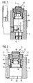
- FIGS 2 and 3 show the adjusting arrangement 14.
- the housing 12 has a recess 54 with an inner wall 56.
- a thermal compensation unit 40 In the recess 54 of the housing 12 a thermal compensation unit 40, a spring retaining element 42 and an adjusting spring 44 are arranged.
- the thermal compensation unit 40 has a first section 45 which is coupled to a piston 46 of the actuator unit 16.
- the spring retaining element 42 has a cylindrical spring retaining element cavity 43 in which a cylindrical second section 48 of the thermal compensation unit 40 is arranged.
- the thermal compensation unit 40 has a thermal compensation unit spring rest 50 and the spring retaining element 42 comprises a spring retaining element spring rest 52, both spring rests 50, 52 supporting the adjusting spring 44 arranged between the thermal compensation unit 40 and the spring retaining element 42.
- the fuel is led from the fluid inlet portion 26 and the housing 12 towards the valve body 20 and then towards the fluid outlet portion 28.
- the fluid flow from the fluid outlet portion 28 to the chamber 38 with the actuator unit 16 is prevented by the bellow 36.
- the valve needle 22 prevents a fluid flow through the fluid outlet portion 28 in the valve body 20 in a closing position of the valve needle 22. Outside of the closing position of the valve needle 22 the valve needle 22 enables the fluid flow through the fluid outlet portion 28.
- the piezoelectric actuator may change its axial length if it gets energized in an expansion duration of some microseconds. By changing its length the actuator unit 16 may effect a force on the valve needle 22. Due to the elasticity of the bellow 36 the valve needle 22 is able to move in axial direction out of the closing position. Outside of the closing position of the valve needle 22 there is a gap between the valve body 20 and the valve needle 22 at an axial end of the injection valve 10 facing away from the actuator unit 16. The gap forms a valve nozzle 29.
- the main spring 30 can force the valve needle 22 via the valve needle spring rest 34 towards the actuator unit 16. In the case that the actuator unit 16 is de-energized the actuator unit 16 shortens its length.
- the main spring 30 can force the valve needle 22 to move in axial direction in its closing position. It is depending on the force balance between the force on the valve needle 22 caused by the actuator unit 16 and the force on the valve needle 22 caused by the main spring 30 whether the valve needle 22 is in its closing position or not.
- the injection valve 10 is provided and coupled with the fluid supply in particular a high pressure fuel chamber.
- the actuator unit 16 is actuated and the gap between the valve body 20 and the valve needle 22 at the axial end of the injection valve 10 facing away from the actuator unit 16 allows to release the fluid flow through the fluid outlet portion 28.
- the spring retaining element 42 is moved in axial direction relative to the housing until a predetermined fluid flow through the fluid outlet portion 28 is obtained.
- the movement of the spring retaining element 42 relative to the housing 12 in direction to the actuator unit 16 results in a compression of the adjusting spring 44 thereby exerting an axial preload force on the actuator unit 16 via the first section 45 of the thermal compensation unit 40.
- the spring retaining element 42 and the housing 12 are crimped together in first crimping directions C1 to obtain a fixed coupling between the spring retaining element 42 and the housing 12.
- the thermal compensation unit 40 and the spring retaining element 42 are crimped together in second crimping directions C2 to obtain a fixed coupling between the thermal compensation unit 40 and the spring retaining element 42.
- the housing 12, the spring retaining element 42 and the thermal compensation unit 40 are fixedly coupled just in the end of the adjusting process.
- the fluid supply can remain to be coupled with the injection valve 10. However, preferably the fluid supply is disconnected from the injection valve after the method for adjusting the injection valve 10 has been carried out.
Landscapes
- Engineering & Computer Science (AREA)
- Chemical & Material Sciences (AREA)
- Combustion & Propulsion (AREA)
- Mechanical Engineering (AREA)
- General Engineering & Computer Science (AREA)
- Manufacturing & Machinery (AREA)
- Fuel-Injection Apparatus (AREA)
Abstract
Description
- The invention relates to a method for adjusting an injection valve.
- Injection valves are in wide spread use, in particular for internal combustion engines where they may be arranged in order to dose the fluid into an intake manifold of the internal combustion engine or directly into the combustion chamber of a cylinder of the internal combustion engine.
- Injection valves for an internal combustion engine comprise actuator units. In order to inject fuel, the actuator unit is energized so that a fluid flow through the fluid outlet portion of the injection valve is enabled.
- In order to enhance the combustion process in view of the creation of unwanted emissions, the respective injection valve may be suited to dose fluids under very high pressures. The pressures may be in case of a gasoline engine, for example, in the range of up to 200 bar and in the case of a diesel engine in the range of up to 2,000 bar. The injection of fluids under such high pressures has to be carried out very precisely.
- Injection valves are calibrated at the end of the manufacturing process to obtain a defined and precise mass flow of the fluid through a fluid outlet portion of the injection valve.
- The object of the invention is to provide a method for adjusting an injection valve which is to be carried out simply and which facilitates a reliable and precise function of the injection valve.
- This object is achieved by the features of the independent claim. Advantageous embodiments of the invention are given in the sub-claims.
- The invention is distinguished by a method for adjusting an injection valve, the injection valve comprising a housing including a central longitudinal axis, the housing comprising a cavity with a fluid outlet portion, a valve needle axially moveable in the cavity, the valve needle preventing a fluid flow through the fluid outlet portion in a closing position and releasing the fluid flow for the fluid outlet portion in further positions, an actuator unit being coupled to the valve needle and enabling the axial movement of the valve needle relative to the valve body upon actuation of the actuator unit, and an adjusting arrangement. The adjusting arrangement comprises a spring retaining element being coupable to the housing, a thermal compensation unit being coupable to the spring retaining element and an adjusting spring arranged between the thermal compensation unit and the spring retaining element and being enabled to exert an axial preload force on the actuator unit. The method comprises the following steps: providing the injection valve and coupling of the injection valve with a fluid supply for the adjustment purpose, actuating of the actuator unit to release the fluid flow through the fluid outlet portion, moving the spring retaining element relative to the housing until a predetermined fluid flow through the fluid outlet portion is obtained, carrying out a fixed coupling of the spring retaining element with the housing, and carrying out a fixed coupling of the thermal compensation unit with the spring retaining element.
- The fixed coupling of the thermal compensation unit with the spring retaining element and the fixed coupling of the spring retaining element with the housing is realized at the end of the adjusting process.
- This has the advantage that it is possible to obtain a precise fixing position of the thermal compensation unit at the end of the adjusting process which allows a secure operation of the thermal compensation unit due to changes of the temperature in the ambience of the injection valve.
- In an advantageous embodiment the coupling of the spring retaining element with the housing is carried out by crimping. In a further advantageous embodiment of the invention the coupling of the thermal compensation unit with the spring retaining element is carried out by crimping. Crimping allows a fast, secure and precise fixed coupling of the participating elements, in particular the spring retaining element and the housing respectively the thermal compensation unit and the spring retaining element.
- Exemplary embodiments of the invention are explained in the following with the aid of schematic drawings. These are as follows:
- Figure 1,
- an injection valve in a longitudinal section view,
- Figure 2,
- an adjusting arrangement for the injection valve according to figure 1 in a longitudinal section view, and
- Figure 3,
- an enlarged view of the adjusting arrangement for the injection valve according to figure 2 in a longitudinal section view.
- Elements of the same design and function that appear in different illustrations are identified by the same reference characters.
- An injection valve 10 (figure 1) that is used as fuel injection valve for an internal combustion engine, comprises a
housing 12, anadjusting arrangement 14 and anactuator unit 16. - The
housing 12 has a tubular shape. Theactuator unit 16 is inserted into thehousing 12 and comprises a piezo actuator, which changes its axial length depending on a control signal applied to it. Theactuator unit 16 may, however, also comprise another type of actuator, which is known to a person skilled in the art for that purpose. Such an actuator may be, for example, a solenoid. - The
injection valve 10 comprises avalve body 20 with a central longitudinal axis A and acavity 24 which is axially led through thevalve body 20. On one of the free ends of thecavity 24, afluid outlet portion 28 is formed, which is closed or open depending on the axial position of avalve needle 22. Theinjection valve 10 further has afluid inlet portion 26 which is arranged in thehousing 12 and which is hydraulically coupled to thecavity 24 and a not shown fuel connector. The fuel connector is designed to be connected to high pressure fuel chamber of an internal combustion engine, the fuel is stored under high pressure, for example, under the pressure of about 200 bar. - The
valve body 20 has a valvebody spring rest 32 and thevalve needle 22 comprises a valveneedle spring rest 34, bothspring rests main spring 30 arranged between thevalve body 20 and thevalve needle 22. - The
injection valve 10 is of an outward opening type. In an alternative embodiment theinjection valve 10 may be of an inward opening type. Between thevalve needle 22 and the valve body 20 abellow 36 is arranged which is sealingly coupling thevalve body 20 with thevalve needle 22. By this a fluid flow between thecavity 24 and a chamber 38 is prevented. Furthermore, thebellow 36 is formed and arranged in a way that thevalve needle 22 is actuable by theactuator unit 16. - Figures 2 and 3 show the
adjusting arrangement 14. Thehousing 12 has arecess 54 with aninner wall 56. In therecess 54 of the housing 12 athermal compensation unit 40, aspring retaining element 42 and an adjustingspring 44 are arranged. Thethermal compensation unit 40 has afirst section 45 which is coupled to apiston 46 of theactuator unit 16. Thespring retaining element 42 has a cylindrical springretaining element cavity 43 in which a cylindricalsecond section 48 of thethermal compensation unit 40 is arranged. - The
thermal compensation unit 40 has a thermal compensationunit spring rest 50 and thespring retaining element 42 comprises a spring retainingelement spring rest 52, bothspring rests spring 44 arranged between thethermal compensation unit 40 and thespring retaining element 42. - In the following, the function of the
injection valve 10 will be described: - The fuel is led from the
fluid inlet portion 26 and thehousing 12 towards thevalve body 20 and then towards thefluid outlet portion 28. The fluid flow from thefluid outlet portion 28 to the chamber 38 with theactuator unit 16 is prevented by thebellow 36. - The
valve needle 22 prevents a fluid flow through thefluid outlet portion 28 in thevalve body 20 in a closing position of thevalve needle 22. Outside of the closing position of thevalve needle 22 thevalve needle 22 enables the fluid flow through thefluid outlet portion 28. - In the case that the
actuator unit 16 has a piezo electric actuator, the piezoelectric actuator may change its axial length if it gets energized in an expansion duration of some microseconds. By changing its length theactuator unit 16 may effect a force on thevalve needle 22. Due to the elasticity of thebellow 36 thevalve needle 22 is able to move in axial direction out of the closing position. Outside of the closing position of thevalve needle 22 there is a gap between thevalve body 20 and thevalve needle 22 at an axial end of theinjection valve 10 facing away from theactuator unit 16. The gap forms avalve nozzle 29. - The
main spring 30 can force thevalve needle 22 via the valveneedle spring rest 34 towards theactuator unit 16. In the case that theactuator unit 16 is de-energized theactuator unit 16 shortens its length. Themain spring 30 can force thevalve needle 22 to move in axial direction in its closing position. It is depending on the force balance between the force on thevalve needle 22 caused by theactuator unit 16 and the force on thevalve needle 22 caused by themain spring 30 whether thevalve needle 22 is in its closing position or not. - In the following, the method for adjusting the
injection valve 10 will be described in detail: - The
injection valve 10 is provided and coupled with the fluid supply in particular a high pressure fuel chamber. Theactuator unit 16 is actuated and the gap between thevalve body 20 and thevalve needle 22 at the axial end of theinjection valve 10 facing away from theactuator unit 16 allows to release the fluid flow through thefluid outlet portion 28. - The
spring retaining element 42 is moved in axial direction relative to the housing until a predetermined fluid flow through thefluid outlet portion 28 is obtained. The movement of thespring retaining element 42 relative to thehousing 12 in direction to theactuator unit 16 results in a compression of the adjustingspring 44 thereby exerting an axial preload force on theactuator unit 16 via thefirst section 45 of thethermal compensation unit 40. If the predetermined fluid flow through thefluid outlet portion 28 is obtained thespring retaining element 42 and thehousing 12 are crimped together in first crimping directions C1 to obtain a fixed coupling between thespring retaining element 42 and thehousing 12. In a further step thethermal compensation unit 40 and thespring retaining element 42 are crimped together in second crimping directions C2 to obtain a fixed coupling between thethermal compensation unit 40 and thespring retaining element 42. - By this, the
housing 12, thespring retaining element 42 and thethermal compensation unit 40 are fixedly coupled just in the end of the adjusting process. This has the advantage that the position of thethermal compensation unit 40 is defined very precisely as the crimping process allows a very exact definition of the positions of the parts which are crimped together. - After carrying out the method for adjusting the
injection valve 10 the fluid supply can remain to be coupled with theinjection valve 10. However, preferably the fluid supply is disconnected from the injection valve after the method for adjusting theinjection valve 10 has been carried out.
Claims (3)
- Method for adjusting an injection valve (10), the injection valve (10) comprising- a housing (12) including a central longitudinal axis (A), the housing (12) comprising a cavity (24) with a fluid outlet portion (28),- a valve needle (22) axially movable in the cavity (24), the valve needle (10) preventing a fluid flow through the fluid outlet portion (44) in a closing position and releasing the fluid flow through the fluid outlet portion (44) in further positions,- an actuator unit (16) being coupled to the valve needle (22) and enabling the axial movement of the valve needle (22) relative to the valve body (20) upon actuation of the actuator unit (16), and- an adjusting arrangement (14) comprising- a spring retaining element (42) being coupable to the housing (12),- a thermal compensation unit (40) being coupable to the spring retaining element (42), and- an adjusting spring (44) arranged between the thermal compensation unit (40) and the spring retaining element (42) and being enabled to exert an axial preload force on the actuator unit (16),the method comprising the following steps:- providing the injection valve (10) and coupling of the injection valve (10) with a fluid supply for the adjustment purpose,- actuating of the actuator unit (16) to release the fluid flow through the fluid outlet portion (28),- moving the spring retaining element (42) relative to the housing (12) until a predetermined fluid flow through the fluid outlet portion (28) is obtained,- carrying out a fixed coupling of the spring retaining element (42) with the housing (12), and carrying out a fixed coupling of the thermal compensation unit (40) with the spring retaining element (42).
- Method in accordance with claim 1 with the coupling of the spring retaining element (42) with the housing (12) is carried out by crimping.
- Method in accordance with claim 1 with the coupling of the thermal compensation unit (40) with the spring retaining element (42) is carried out by crimping.
Priority Applications (2)
| Application Number | Priority Date | Filing Date | Title |
|---|---|---|---|
| DE200660011587 DE602006011587D1 (en) | 2006-06-06 | 2006-06-06 | Method for adjusting a fuel injection valve |
| EP20060011630 EP1865194B1 (en) | 2006-06-06 | 2006-06-06 | Method for adjusting an injection valve |
Applications Claiming Priority (1)
| Application Number | Priority Date | Filing Date | Title |
|---|---|---|---|
| EP20060011630 EP1865194B1 (en) | 2006-06-06 | 2006-06-06 | Method for adjusting an injection valve |
Publications (2)
| Publication Number | Publication Date |
|---|---|
| EP1865194A1 true EP1865194A1 (en) | 2007-12-12 |
| EP1865194B1 EP1865194B1 (en) | 2010-01-06 |
Family
ID=37160742
Family Applications (1)
| Application Number | Title | Priority Date | Filing Date |
|---|---|---|---|
| EP20060011630 Ceased EP1865194B1 (en) | 2006-06-06 | 2006-06-06 | Method for adjusting an injection valve |
Country Status (2)
| Country | Link |
|---|---|
| EP (1) | EP1865194B1 (en) |
| DE (1) | DE602006011587D1 (en) |
Citations (4)
| Publication number | Priority date | Publication date | Assignee | Title |
|---|---|---|---|---|
| EP1445477A1 (en) * | 2003-01-24 | 2004-08-11 | Siemens VDO Automotive S.p.A. | Metering device with flow calibrator and method for setting a flow rate of a metering device |
| EP1450036A1 (en) * | 2003-02-20 | 2004-08-25 | Siemens VDO Automotive S.p.A. | Metering device and method for setting a spring preload |
| US20050056706A1 (en) * | 2003-08-08 | 2005-03-17 | Crofts John D. | Piezoelectric control valve adjustment method |
| EP1593841A1 (en) * | 2004-05-04 | 2005-11-09 | Robert Bosch Gmbh | Fuel injection valve |
-
2006
- 2006-06-06 DE DE200660011587 patent/DE602006011587D1/en active Active
- 2006-06-06 EP EP20060011630 patent/EP1865194B1/en not_active Ceased
Patent Citations (4)
| Publication number | Priority date | Publication date | Assignee | Title |
|---|---|---|---|---|
| EP1445477A1 (en) * | 2003-01-24 | 2004-08-11 | Siemens VDO Automotive S.p.A. | Metering device with flow calibrator and method for setting a flow rate of a metering device |
| EP1450036A1 (en) * | 2003-02-20 | 2004-08-25 | Siemens VDO Automotive S.p.A. | Metering device and method for setting a spring preload |
| US20050056706A1 (en) * | 2003-08-08 | 2005-03-17 | Crofts John D. | Piezoelectric control valve adjustment method |
| EP1593841A1 (en) * | 2004-05-04 | 2005-11-09 | Robert Bosch Gmbh | Fuel injection valve |
Also Published As
| Publication number | Publication date |
|---|---|
| EP1865194B1 (en) | 2010-01-06 |
| DE602006011587D1 (en) | 2010-02-25 |
Similar Documents
| Publication | Publication Date | Title |
|---|---|---|
| EP2000662B1 (en) | Adjusting and filter arrangement for an injection valve and injection valve | |
| EP2333297B1 (en) | Valve assembly for an injection valve and injection valve | |
| EP2535552B1 (en) | Valve assembly for an injection valve and injection valve | |
| EP2602476A1 (en) | Valve assembly means for an injection valve and injection valve | |
| KR101857463B1 (en) | Valve assembly for an injection valve, injection valve and method for assembling a valve assembly of an injection valve | |
| CN104583576B (en) | Valve assemblies and injection valves for injection valves | |
| EP1995447B1 (en) | Valve assembly for an injection valve and injection valve | |
| EP1561942B1 (en) | Fluid injector and its method of manufacture | |
| EP1865194B1 (en) | Method for adjusting an injection valve | |
| EP2375051A1 (en) | Valve assembly for an injection valve and injection valve | |
| EP1865191A1 (en) | Adjusting arrangement for an injection valve, injection valve and method for adjusting an injection valve | |
| EP2080895B1 (en) | Thermal compensation arrangement and injection valve | |
| EP2003331A1 (en) | Valve assembly for an injection valve and injection valve | |
| EP2466109A1 (en) | Valve assembly for an injection valve and injection valve | |
| EP1803929B1 (en) | Fluid injector and method for manufacturing a fluid injector | |
| EP1887216B1 (en) | Thermal compensation arrangement in an injection valve | |
| EP2067981B1 (en) | Valve assembly for an injection valve and injection valve | |
| EP2003327A1 (en) | Actuator unit for an injection valve and injection valve | |
| EP1574705B1 (en) | Fluid injector | |
| EP2607680A1 (en) | Method for manufacturing an injection valve | |
| EP2003329B1 (en) | Electrical connector for an injector, actuator unit for an injector, injector and method for coupling a first connector element to a second connector element of an electrical connector for an injector | |
| EP2216542A1 (en) | Valve assembly for an injection valve and injection valve | |
| US8286893B2 (en) | Fuel injector | |
| EP2228532B1 (en) | Method for assembling a valve assembly of an injection valve and valve assembly of an injection valve | |
| CN1977106A (en) | Fuel injection valve |
Legal Events
| Date | Code | Title | Description |
|---|---|---|---|
| PUAI | Public reference made under article 153(3) epc to a published international application that has entered the european phase |
Free format text: ORIGINAL CODE: 0009012 |
|
| AK | Designated contracting states |
Kind code of ref document: A1 Designated state(s): AT BE BG CH CY CZ DE DK EE ES FI FR GB GR HU IE IS IT LI LT LU LV MC NL PL PT RO SE SI SK TR |
|
| AX | Request for extension of the european patent |
Extension state: AL BA HR MK YU |
|
| 17P | Request for examination filed |
Effective date: 20080612 |
|
| AKX | Designation fees paid |
Designated state(s): DE FR IT |
|
| RAP1 | Party data changed (applicant data changed or rights of an application transferred) |
Owner name: CONTINENTAL AUTOMOTIVE GMBH |
|
| GRAP | Despatch of communication of intention to grant a patent |
Free format text: ORIGINAL CODE: EPIDOSNIGR1 |
|
| GRAS | Grant fee paid |
Free format text: ORIGINAL CODE: EPIDOSNIGR3 |
|
| GRAA | (expected) grant |
Free format text: ORIGINAL CODE: 0009210 |
|
| AK | Designated contracting states |
Kind code of ref document: B1 Designated state(s): DE FR IT |
|
| REF | Corresponds to: |
Ref document number: 602006011587 Country of ref document: DE Date of ref document: 20100225 Kind code of ref document: P |
|
| PLBE | No opposition filed within time limit |
Free format text: ORIGINAL CODE: 0009261 |
|
| STAA | Information on the status of an ep patent application or granted ep patent |
Free format text: STATUS: NO OPPOSITION FILED WITHIN TIME LIMIT |
|
| 26N | No opposition filed |
Effective date: 20101007 |
|
| REG | Reference to a national code |
Ref country code: FR Ref legal event code: PLFP Year of fee payment: 11 |
|
| REG | Reference to a national code |
Ref country code: FR Ref legal event code: PLFP Year of fee payment: 12 |
|
| REG | Reference to a national code |
Ref country code: FR Ref legal event code: PLFP Year of fee payment: 13 |
|
| PGFP | Annual fee paid to national office [announced via postgrant information from national office to epo] |
Ref country code: DE Payment date: 20180630 Year of fee payment: 13 |
|
| PGFP | Annual fee paid to national office [announced via postgrant information from national office to epo] |
Ref country code: FR Payment date: 20180620 Year of fee payment: 13 |
|
| PGFP | Annual fee paid to national office [announced via postgrant information from national office to epo] |
Ref country code: IT Payment date: 20180627 Year of fee payment: 13 |
|
| REG | Reference to a national code |
Ref country code: DE Ref legal event code: R119 Ref document number: 602006011587 Country of ref document: DE |
|
| PG25 | Lapsed in a contracting state [announced via postgrant information from national office to epo] |
Ref country code: IT Free format text: LAPSE BECAUSE OF NON-PAYMENT OF DUE FEES Effective date: 20190606 Ref country code: DE Free format text: LAPSE BECAUSE OF NON-PAYMENT OF DUE FEES Effective date: 20200101 |
|
| PG25 | Lapsed in a contracting state [announced via postgrant information from national office to epo] |
Ref country code: FR Free format text: LAPSE BECAUSE OF NON-PAYMENT OF DUE FEES Effective date: 20190630 |