EP1865183A2 - Method of manufacturing a cylinder block - Google Patents
Method of manufacturing a cylinder block Download PDFInfo
- Publication number
- EP1865183A2 EP1865183A2 EP07109103A EP07109103A EP1865183A2 EP 1865183 A2 EP1865183 A2 EP 1865183A2 EP 07109103 A EP07109103 A EP 07109103A EP 07109103 A EP07109103 A EP 07109103A EP 1865183 A2 EP1865183 A2 EP 1865183A2
- Authority
- EP
- European Patent Office
- Prior art keywords
- cylinder
- partition walls
- runoff
- cylinder block
- crankcase
- Prior art date
- Legal status (The legal status is an assumption and is not a legal conclusion. Google has not performed a legal analysis and makes no representation as to the accuracy of the status listed.)
- Granted
Links
Images



Classifications
-
- F—MECHANICAL ENGINEERING; LIGHTING; HEATING; WEAPONS; BLASTING
- F02—COMBUSTION ENGINES; HOT-GAS OR COMBUSTION-PRODUCT ENGINE PLANTS
- F02F—CYLINDERS, PISTONS OR CASINGS, FOR COMBUSTION ENGINES; ARRANGEMENTS OF SEALINGS IN COMBUSTION ENGINES
- F02F7/00—Casings, e.g. crankcases
- F02F7/0002—Cylinder arrangements
- F02F7/0007—Crankcases of engines with cylinders in line
-
- F—MECHANICAL ENGINEERING; LIGHTING; HEATING; WEAPONS; BLASTING
- F01—MACHINES OR ENGINES IN GENERAL; ENGINE PLANTS IN GENERAL; STEAM ENGINES
- F01M—LUBRICATING OF MACHINES OR ENGINES IN GENERAL; LUBRICATING INTERNAL COMBUSTION ENGINES; CRANKCASE VENTILATING
- F01M13/00—Crankcase ventilating or breathing
- F01M13/04—Crankcase ventilating or breathing having means for purifying air before leaving crankcase, e.g. removing oil
-
- Y—GENERAL TAGGING OF NEW TECHNOLOGICAL DEVELOPMENTS; GENERAL TAGGING OF CROSS-SECTIONAL TECHNOLOGIES SPANNING OVER SEVERAL SECTIONS OF THE IPC; TECHNICAL SUBJECTS COVERED BY FORMER USPC CROSS-REFERENCE ART COLLECTIONS [XRACs] AND DIGESTS
- Y10—TECHNICAL SUBJECTS COVERED BY FORMER USPC
- Y10T—TECHNICAL SUBJECTS COVERED BY FORMER US CLASSIFICATION
- Y10T29/00—Metal working
- Y10T29/49—Method of mechanical manufacture
- Y10T29/49229—Prime mover or fluid pump making
-
- Y—GENERAL TAGGING OF NEW TECHNOLOGICAL DEVELOPMENTS; GENERAL TAGGING OF CROSS-SECTIONAL TECHNOLOGIES SPANNING OVER SEVERAL SECTIONS OF THE IPC; TECHNICAL SUBJECTS COVERED BY FORMER USPC CROSS-REFERENCE ART COLLECTIONS [XRACs] AND DIGESTS
- Y10—TECHNICAL SUBJECTS COVERED BY FORMER USPC
- Y10T—TECHNICAL SUBJECTS COVERED BY FORMER US CLASSIFICATION
- Y10T29/00—Metal working
- Y10T29/49—Method of mechanical manufacture
- Y10T29/49229—Prime mover or fluid pump making
- Y10T29/49231—I.C. [internal combustion] engine making
-
- Y—GENERAL TAGGING OF NEW TECHNOLOGICAL DEVELOPMENTS; GENERAL TAGGING OF CROSS-SECTIONAL TECHNOLOGIES SPANNING OVER SEVERAL SECTIONS OF THE IPC; TECHNICAL SUBJECTS COVERED BY FORMER USPC CROSS-REFERENCE ART COLLECTIONS [XRACs] AND DIGESTS
- Y10—TECHNICAL SUBJECTS COVERED BY FORMER USPC
- Y10T—TECHNICAL SUBJECTS COVERED BY FORMER US CLASSIFICATION
- Y10T29/00—Metal working
- Y10T29/49—Method of mechanical manufacture
- Y10T29/49229—Prime mover or fluid pump making
- Y10T29/49231—I.C. [internal combustion] engine making
- Y10T29/49234—Rotary or radial engine making
-
- Y—GENERAL TAGGING OF NEW TECHNOLOGICAL DEVELOPMENTS; GENERAL TAGGING OF CROSS-SECTIONAL TECHNOLOGIES SPANNING OVER SEVERAL SECTIONS OF THE IPC; TECHNICAL SUBJECTS COVERED BY FORMER USPC CROSS-REFERENCE ART COLLECTIONS [XRACs] AND DIGESTS
- Y10—TECHNICAL SUBJECTS COVERED BY FORMER USPC
- Y10T—TECHNICAL SUBJECTS COVERED BY FORMER US CLASSIFICATION
- Y10T29/00—Metal working
- Y10T29/49—Method of mechanical manufacture
- Y10T29/49229—Prime mover or fluid pump making
- Y10T29/4927—Cylinder, cylinder head or engine valve sleeve making
Definitions
- the present invention relates to a method of manufacturing a cylinder block for an engine and particularly, but not exclusively, a multi-cylinder engine that has a crankcase in which a plurality of crank chambers are aligned with corresponding cylinders in the direction of a crankshaft and the adjacent crank chambers are separated by partition walls.
- Aspects of the invention relate to a method of manufacturing a cylinder block for a multi-cylinder engine, whereby ventilating communication holes are suitably formed in the partition walls so that the crank chambers may communicate with one another.
- Other aspects of the invention relate to a cylinder block, to an engine and to a vehicle.
- a conventional crankcase having a cylinder block for a multi-cylinder engine is designed such that a plurality of adjacent crank chambers are aligned with corresponding cylinders in the direction of a crankshaft.
- Partition walls separating the adjacent crank chambers usually have ventilating communication holes such that the crank chambers communicate with one another. This may help reduce friction by eliminating the problem of changes in internal pressure in any of the crank chambers arising from the reciprocating motion of corresponding pistons increasing with engine speed (refer to Japanese Patent Application Laid-Open No. 2000-136752 ).
- a cylinder block for a multi-cylinder engine is a Siamese cylinder block designed such that part of each cylinder wall is shared by adjacent cylinder bores. Therefore, each cylinder wall between adjacent cylinder bores is thinner than each partition wall formed in the crankcase.
- the cylinder-bore side of each partition wall has a honing runoff portion that is continuous with the corresponding cylinder bore.
- each partition wall includes a thin honing runoff portion and a thick partition wall portion extending below from the honing runoff portion via a step.
- the communication holes defined by thick partition walls may affect the support strength of a bearing provided for a crankshaft.
- the communication holes may be formed in the honing runoff portions located away from the bearing for the crankshaft.
- the communication holes are formed across the corresponding thin honing runoff portions and thick partition walls.
- a machine may be used to form such larger communication holes in the partition walls of a cast cylinder block, parallel to the central axis of the crankshaft.
- the machine may require boring through not only the partition walls with the honing runoff portions, but also the portions including the steps. In this case, the tool may strike against the thick partition walls, thereby decreasing the processing accuracy and yield for the communication holes.
- boundaries between the corresponding steps and communication holes form edges, where stress may tend to concentrate. These stress concentrations may limit the size of the communication holes.
- a method of manufacturing a cylinder block for a multi-cylinder engine wherein the cylinder block comprises a crankcase and cylinder bores disposed therein separated by cylinder walls, wherein the crankcase is adapted to receive a crankshaft and comprises crank chambers disposed therein separated by partition walls, wherein each of the crank chambers of the crankcase corresponds to one of the cylinder bores of the cylinder block, wherein a cylinder bore side of each partition wall comprises a honing runoff portion thinner in section than a crankshaft side thereof such that a step face results in each partition wall, the method comprising forming a runoff groove in the step face of at least one of the partition walls of the crank chambers and after the runoff groove is formed, forming a communication hole at least partially within the runoff groove in the at least one of the partition walls to enable communication between crank chambers.
- the forming the communication hole in at least one of the partition walls comprises forming the communication hole in each of the partition walls.
- the forming the communication hole in each of the partition walls comprises inserting a cutting tool from one end of the crankcase to bore through the partition walls in a direction substantially parallel to the crankshaft.
- the runoff groove is formed with a die cast mold.
- the method may comprise forming a chamfer between the runoff groove and the step face of at least one of the partition walls.
- a cooling jacket is disposed about at least one of the cylinder bores.
- the communication hole is completely within the honing runoff portion and the runoff groove.
- a cylinder block for a multi-cylinder engine comprising a crankcase and cylinder bores disposed therein separated by cylinder walls, wherein the crankcase is adapted to receive a crankshaft and comprises crank chambers disposed therein separated by partition walls, wherein each of the crank chambers of the crankcase corresponds to one of the cylinder bores of the cylinder block and wherein a cylinder bore side of each partition wall comprises a honing runoff portion thinner in section than a crankshaft side thereof such that a step face results in each partition wall, the cylinder block comprising a runoff groove formed in the step face of at least one of the partition walls of the crank chambers and a communication hole formed at least partially within the runoff groove in the at least one of the partition walls to enable communication between crank chambers.
- a method of manufacturing a cylinder block for a multi-cylinder engine includes a crankcase and cylinder bores disposed therein separated by cylinder walls.
- the crankcase is adapted to receive a crankshaft and includes crank chambers disposed therein separated by partition walls.
- the crank chambers of the crankcase correspond to one of the cylinder bores of the cylinder block.
- the cylinder bore side of each partition wall has a honing runoff portion thinner in section than the crankshaft side thereof such that a step face results in the partition walls.
- the method further includes forming a runoff groove in the step face of at least one of the partition walls of the crank chambers and forming a communication hole at least partially within the runoff groove in the at least one of the partition walls to enable communication between crank chambers.
- FIGS. 1 to 4 a method for manufacturing a cylinder block for a multi-cylinder engine is described with reference to the drawings in accordance with an embodiment of the present invention.
- the top deck of the cylinder block is on the upper side, and the crankshaft on the lower side. Additionally, like items in the drawing figures are shown with the same reference numbers.
- crankcase 1 for a multi-cylinder engine in accordance with an embodiment of the present invention is shown.
- the crankcase 1 may be formed by die casting a light alloy, such as an aluminum alloy, so that the crankcase 1 is integrated with a cylinder block 2 having cylinder bores 10.
- the cylinder block 2 may be such that the cylinder bores 10, possibly surrounded by one or more cooling jackets 11, are disposed in the form of a V shape along the axial direction of a crankshaft 6a.
- the crankcase 1 may be integrally disposed below the cylinder block 2 and may accommodate the crankshaft 6a.
- partition walls 4 Integrally disposed within the crankcase 1 are partition walls 4 (i.e., bulkheads) that may section the interior of the crankcase 1 into crank chambers 3 for the corresponding cylinder bores 10 such that the partition walls 4 are disposed between the cylinder bores 10.
- the cylinder bores 10 disposed in corresponding banks forming a V shape are offset with respect to one another in the direction of the crankshaft.
- cylinder walls 12 between the cylinder bores 10 on both banks may also offset in the direction of the crankshaft.
- each partition wall 4 is formed such that a step face 5 (i.e., an area surrounded by an arcuate honing runoff portion, described below, and one of the edges of the partition wall 4) facing the corresponding cylinder bore 10 is exposed from one side of the cylinder bore 10, as shown in FIG. 3.
- a step face 5 i.e., an area surrounded by an arcuate honing runoff portion, described below, and one of the edges of the partition wall 4
- each partition wall 4 Formed in each partition wall 4 is a semicircular groove 6 to support a crank journal of the crankshaft 6a via a bearing metal.
- the cylinder bore 10 side of each partition wall 4 may have a honing runoff portion 7.
- the honing runoff portion 7 may recede toward the crankshaft 6a side of the corresponding cylinder bore 10.
- the honing runoff portion 7 may be thinner than the crankshaft side partition wall 4.
- the partition wall 4 is continuous with the honing runoff portion 7 from the step face 5 so as to connect between the cylinder bores 10 through the corresponding cylinder wall 12.
- each runoff groove 8 Formed in the middle of the step face 5 of each partition wall 4 is a runoff groove 8 extending in the direction of the crankshaft and having an arcuate section in the direction perpendicular to the crankshaft. A boundary between each runoff groove 8 and the corresponding step face 5 may be connected by a smooth and curved chamfer 8a.
- the runoff grooves 8 in the step faces 5 of the partition walls 4 of the cylinder block 2 may be formed by die casting. Specifically, each runoff groove 8 may be formed as described below. A projection of an arcuate section is integrally formed in part of the face of a die cast mold and disposed in a cavity in order to form the honing runoff portion 7, and then the casting is removed. By forming the runoff groove 8 by the removal of the casting as described above, a smooth connection with the step face 5 can be made simply by means of the die cast mold. This facilitates the manufacture and restrains shrinkage of the cavity during casting.
- the communication holes 20 may be formed by a boring process performed by inserting a cutting tool, such as a drill, parallel to the crankshaft from one end of the crankcase 1 in the direction of the crankshaft and then boring through the partition walls 4.
- the runoff grooves 8 may be formed in the step faces 5 before forming the communications holes 20 to prevent the cutting tool from being displaced as a result of mis-striking against any step face 5. This allows for greater accuracy in shaping the communication holes 20. This also prevents the lifetime of the tool from diminishing due to stress from such strikes. Further, forming the runoff grooves 8 in advance reduces the processing cost and prolong the lifetime of the tool, in comparison to the case of boring through the partition walls 4 together with the step faces 5.
- the chamfer 8a formed at each boundary between the corresponding runoff groove 8 and step face 5 can reduce stress concentration, which may be more likely to occur in the case where the boundary between the step face 5 and runoff groove 8 form an edge.
- a larger inner diameter of the runoff grooves 8 allows a relatively larger diameter of the communication holes 20.
- the increase in diameter of the communication holes 20 decreases passage resistance in the communication hole 20.
- Chamfering boundaries between the corresponding step faces 5 and runoff grooves 8 may decrease air-flow resistance around the communication holes 20 and may reduce passage resistance between the adjacent crank chambers 3.
- each cylinder wall 12 between cylinder bores 10 is disposed in the middle of a corresponding partition wall 30 in the direction of a crankshaft. Therefore, it may be necessary for both sides of the partition wall 30 to have step faces 5 that face the cylinder bores 10.
- runoff grooves 8 in the corresponding step faces 5 by die casting as in the case of the cylinder block for the V-type multi-cylinder engine, the same effects described above can be exhibited.
Landscapes
- Engineering & Computer Science (AREA)
- Chemical & Material Sciences (AREA)
- Combustion & Propulsion (AREA)
- Mechanical Engineering (AREA)
- General Engineering & Computer Science (AREA)
- Cylinder Crankcases Of Internal Combustion Engines (AREA)
Abstract
Description
- The present invention relates to a method of manufacturing a cylinder block for an engine and particularly, but not exclusively, a multi-cylinder engine that has a crankcase in which a plurality of crank chambers are aligned with corresponding cylinders in the direction of a crankshaft and the adjacent crank chambers are separated by partition walls. Aspects of the invention relate to a method of manufacturing a cylinder block for a multi-cylinder engine, whereby ventilating communication holes are suitably formed in the partition walls so that the crank chambers may communicate with one another. Other aspects of the invention relate to a cylinder block, to an engine and to a vehicle.
- A conventional crankcase having a cylinder block for a multi-cylinder engine is designed such that a plurality of adjacent crank chambers are aligned with corresponding cylinders in the direction of a crankshaft. Partition walls separating the adjacent crank chambers usually have ventilating communication holes such that the crank chambers communicate with one another. This may help reduce friction by eliminating the problem of changes in internal pressure in any of the crank chambers arising from the reciprocating motion of corresponding pistons increasing with engine speed (refer to
Japanese Patent Application Laid-Open No. 2000-136752 - Generally, a cylinder block for a multi-cylinder engine is a Siamese cylinder block designed such that part of each cylinder wall is shared by adjacent cylinder bores. Therefore, each cylinder wall between adjacent cylinder bores is thinner than each partition wall formed in the crankcase. In order to prevent a tool used for honing the cylinder bores from interfering with the partition walls, the cylinder-bore side of each partition wall has a honing runoff portion that is continuous with the corresponding cylinder bore. In other words, each partition wall includes a thin honing runoff portion and a thick partition wall portion extending below from the honing runoff portion via a step.
- However, the communication holes defined by thick partition walls may affect the support strength of a bearing provided for a crankshaft. To avoid this, the communication holes may be formed in the honing runoff portions located away from the bearing for the crankshaft. On the other hand, because the larger communication holes reduce the passage resistance of the communication holes, the communication holes are formed across the corresponding thin honing runoff portions and thick partition walls. A machine may be used to form such larger communication holes in the partition walls of a cast cylinder block, parallel to the central axis of the crankshaft. However, the machine may require boring through not only the partition walls with the honing runoff portions, but also the portions including the steps. In this case, the tool may strike against the thick partition walls, thereby decreasing the processing accuracy and yield for the communication holes. In addition, boundaries between the corresponding steps and communication holes form edges, where stress may tend to concentrate. These stress concentrations may limit the size of the communication holes.
- It is an aim of the invention to address this issue and to improve upon known technology. Other aims and advantages of the invention will become apparent from the following description, claims and drawings.
- Aspects of the invention therefore provide a method, a cylinder block, an engine and a vehicle as claimed in the appended claims.
- According to another aspect of the invention there is provided a method of manufacturing a cylinder block for a multi-cylinder engine, wherein the cylinder block comprises a crankcase and cylinder bores disposed therein separated by cylinder walls, wherein the crankcase is adapted to receive a crankshaft and comprises crank chambers disposed therein separated by partition walls, wherein each of the crank chambers of the crankcase corresponds to one of the cylinder bores of the cylinder block, wherein a cylinder bore side of each partition wall comprises a honing runoff portion thinner in section than a crankshaft side thereof such that a step face results in each partition wall, the method comprising forming a runoff groove in the step face of at least one of the partition walls of the crank chambers and after the runoff groove is formed, forming a communication hole at least partially within the runoff groove in the at least one of the partition walls to enable communication between crank chambers.
- In an embodiment, the forming the communication hole in at least one of the partition walls comprises forming the communication hole in each of the partition walls.
- In an embodiment, the forming the communication hole in each of the partition walls comprises inserting a cutting tool from one end of the crankcase to bore through the partition walls in a direction substantially parallel to the crankshaft. In an embodiment, the runoff groove is formed with a die cast mold.
- The method may comprise forming a chamfer between the runoff groove and the step face of at least one of the partition walls.
- In an embodiment, a cooling jacket is disposed about at least one of the cylinder bores.
- In an embodiment, the communication hole is completely within the honing runoff portion and the runoff groove.
- According to another aspect of the invention there is provided a cylinder block manufactured in accordance with any preceding paragraph.
- According to a further aspect of the invention there is provided a cylinder block for a multi-cylinder engine comprising a crankcase and cylinder bores disposed therein separated by cylinder walls, wherein the crankcase is adapted to receive a crankshaft and comprises crank chambers disposed therein separated by partition walls, wherein each of the crank chambers of the crankcase corresponds to one of the cylinder bores of the cylinder block and wherein a cylinder bore side of each partition wall comprises a honing runoff portion thinner in section than a crankshaft side thereof such that a step face results in each partition wall, the cylinder block comprising a runoff groove formed in the step face of at least one of the partition walls of the crank chambers and a communication hole formed at least partially within the runoff groove in the at least one of the partition walls to enable communication between crank chambers.
- For example, a method of manufacturing a cylinder block for a multi-cylinder engine is provided. The cylinder block includes a crankcase and cylinder bores disposed therein separated by cylinder walls. The crankcase is adapted to receive a crankshaft and includes crank chambers disposed therein separated by partition walls. The crank chambers of the crankcase correspond to one of the cylinder bores of the cylinder block. The cylinder bore side of each partition wall has a honing runoff portion thinner in section than the crankshaft side thereof such that a step face results in the partition walls. The method further includes forming a runoff groove in the step face of at least one of the partition walls of the crank chambers and forming a communication hole at least partially within the runoff groove in the at least one of the partition walls to enable communication between crank chambers.
- Within the scope of this application it is envisaged that the various aspects, embodiments, examples, features and alternatives set out in the preceding paragraphs, in the claims and/or in the following description may be taken individually or in any combination thereof.
- The present invention will now be described, by way of example only, with reference to the accompanying drawings in which:
- FIG. 1 is a sectional view perpendicular to a crankshaft disposed in a cylinder block for a multi-cylinder engine in accordance with an embodiment of the present invention;
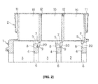
- FIG. 2 is a sectional view along the crankshaft of the cylinder block in accordance with an embodiment of the present invention;
- FIG. 3 is a top view from a top deck of the cylinder block in accordance with an embodiment of the present invention;
- FIG. 4 is a perspective view from the top deck as it faces communication holes in corresponding partition walls in accordance with an embodiment of the present invention;
- FIG. 5 is an enlarged view of the main part of each communication hole in accordance with an embodiment of the present invention;
- FIG. 6 is a sectional view showing the direction in which holes are bored by a boring tool in accordance with an embodiment of the present invention;
- FIG. 7 is a perspective view from the top deck showing the same direction in which the holes are bored by the boring tool in accordance with an embodiment of the present invention;
- FIG. 8 is a sectional view of the main part of each of the partition walls of a cylinder block mounted in an in-line multi-cylinder engine in accordance with an embodiment of the present invention;
- Referring to FIGS. 1 to 4, a method for manufacturing a cylinder block for a multi-cylinder engine is described with reference to the drawings in accordance with an embodiment of the present invention. In the description given below, it is assumed that the top deck of the cylinder block is on the upper side, and the crankshaft on the lower side. Additionally, like items in the drawing figures are shown with the same reference numbers.
- Referring to FIGS. 1 to 4, a crankcase 1 for a multi-cylinder engine in accordance with an embodiment of the present invention is shown. The crankcase 1 may be formed by die casting a light alloy, such as an aluminum alloy, so that the crankcase 1 is integrated with a
cylinder block 2 havingcylinder bores 10. Specifically, thecylinder block 2 may be such that the cylinder bores 10, possibly surrounded by one ormore cooling jackets 11, are disposed in the form of a V shape along the axial direction of acrankshaft 6a. As such, the crankcase 1 may be integrally disposed below thecylinder block 2 and may accommodate thecrankshaft 6a. - Integrally disposed within the crankcase 1 are partition walls 4 (i.e., bulkheads) that may section the interior of the crankcase 1 into
crank chambers 3 for thecorresponding cylinder bores 10 such that thepartition walls 4 are disposed between thecylinder bores 10. In this embodiment, thecylinder bores 10 disposed in corresponding banks forming a V shape are offset with respect to one another in the direction of the crankshaft. As such,cylinder walls 12 between the cylinder bores 10 on both banks may also offset in the direction of the crankshaft. Accordingly, eachpartition wall 4 is formed such that a step face 5 (i.e., an area surrounded by an arcuate honing runoff portion, described below, and one of the edges of the partition wall 4) facing thecorresponding cylinder bore 10 is exposed from one side of thecylinder bore 10, as shown in FIG. 3. - Formed in each
partition wall 4 is asemicircular groove 6 to support a crank journal of thecrankshaft 6a via a bearing metal. In order to prevent a tool for honing thecylinder bores 10 from interfering with thepartition walls 4, the cylinder bore 10 side of eachpartition wall 4 may have ahoning runoff portion 7. As such, thehoning runoff portion 7 may recede toward thecrankshaft 6a side of the corresponding cylinder bore 10. In a section in the direction of the crankshaft, thehoning runoff portion 7 may be thinner than the crankshaftside partition wall 4. Thepartition wall 4 is continuous with thehoning runoff portion 7 from thestep face 5 so as to connect between thecylinder bores 10 through thecorresponding cylinder wall 12. - Formed in the middle of the
step face 5 of eachpartition wall 4 is arunoff groove 8 extending in the direction of the crankshaft and having an arcuate section in the direction perpendicular to the crankshaft. A boundary between eachrunoff groove 8 and thecorresponding step face 5 may be connected by a smooth andcurved chamfer 8a. - The
runoff grooves 8 in the step faces 5 of thepartition walls 4 of thecylinder block 2 may be formed by die casting. Specifically, eachrunoff groove 8 may be formed as described below. A projection of an arcuate section is integrally formed in part of the face of a die cast mold and disposed in a cavity in order to form the honingrunoff portion 7, and then the casting is removed. By forming therunoff groove 8 by the removal of the casting as described above, a smooth connection with thestep face 5 can be made simply by means of the die cast mold. This facilitates the manufacture and restrains shrinkage of the cavity during casting. - A
communication hole 20, through which the adjacent crankchambers 3 communicate, is formed in eachpartition wall 4 so as to extend from an end 9 of therunoff groove 8 in the direction of the crankshaft as far as the honingrunoff portion 7. As shown in FIGS. 6 and 7, the communication holes 20 may be formed by a boring process performed by inserting a cutting tool, such as a drill, parallel to the crankshaft from one end of the crankcase 1 in the direction of the crankshaft and then boring through thepartition walls 4. - In the boring process, the
runoff grooves 8 may be formed in the step faces 5 before forming the communications holes 20 to prevent the cutting tool from being displaced as a result of mis-striking against anystep face 5. This allows for greater accuracy in shaping the communication holes 20. This also prevents the lifetime of the tool from diminishing due to stress from such strikes. Further, forming therunoff grooves 8 in advance reduces the processing cost and prolong the lifetime of the tool, in comparison to the case of boring through thepartition walls 4 together with the step faces 5. - Further, the
chamfer 8a formed at each boundary between thecorresponding runoff groove 8 and stepface 5 can reduce stress concentration, which may be more likely to occur in the case where the boundary between thestep face 5 andrunoff groove 8 form an edge. This means that a larger inner diameter of therunoff grooves 8 allows a relatively larger diameter of the communication holes 20. The increase in diameter of the communication holes 20 decreases passage resistance in thecommunication hole 20. Chamfering boundaries between the corresponding step faces 5 andrunoff grooves 8 may decrease air-flow resistance around the communication holes 20 and may reduce passage resistance between the adjacent crankchambers 3. - In the foregoing embodiment, a description of a cylinder block for a V-type multi-cylinder engine was given. However, the embodiment can also be applied to a cylinder block for an in-line multi-cylinder engine. Specifically, as shown in FIG. 8, in the cylinder block of the in-line multi-cylinder engine, each
cylinder wall 12 between cylinder bores 10 is disposed in the middle of acorresponding partition wall 30 in the direction of a crankshaft. Therefore, it may be necessary for both sides of thepartition wall 30 to have step faces 5 that face the cylinder bores 10. By formingrunoff grooves 8 in the corresponding step faces 5 by die casting as in the case of the cylinder block for the V-type multi-cylinder engine, the same effects described above can be exhibited. - While this invention has been described with respect to a limited number of embodiments, those skilled in the art, having benefit of this disclosure, will appreciate that other embodiments may be devised which do not depart from the scope of the invention as disclosed herein. Accordingly, the scope of the invention should be limited only by the attached claims.
- This application claims priority from
Japanese Patent Application No. JP 2006-151392, filed 31st May 2006
Claims (9)
- A method of manufacturing a cylinder block for a multi-cylinder engine having a crankcase and cylinder bores disposed therein separated by cylinder walls, wherein the crankcase is adapted to receive a crankshaft and comprises crank chambers disposed therein separated by partition walls, each of the crank chambers of the crankcase corresponding to one of the cylinder bores of the cylinder block wherein a cylinder bore side of each partition wall comprises a honing runoff portion thinner in section than a crankshaft side thereof such that a step face results in each partition wall, the method comprising:forming a runoff groove in the step face of at least one of the partition walls of the crank chambers; andafter the runoff groove is formed, forming a communication hole at least partially within the runoff groove in the at least one of the partition walls to enable communication between crank chambers.
- A method as claimed in claim 1, wherein forming the communication hole in at least one of the partition walls comprises forming the communication hole in each of the partition walls.
- A method as claimed in claim 2, wherein forming the communication hole in each of the partition walls comprises inserting a cutting tool from one end of the crankcase to bore through the partition walls in a direction substantially parallel to the crankshaft.
- A method as claimed in any preceding claim, wherein the runoff groove is formed with a die cast mold.
- A method as claimed in any preceding claim comprising forming a chamfer between the runoff groove and the step face of at least one of the partition walls.
- A method as claimed in any preceding claim, wherein a cooling jacket is disposed about at least one of the cylinder bores.
- A method as claimed in any preceding claim, wherein the communication hole is completely within the honing runoff portion and the runoff groove.
- A cylinder block manufactured using a method as claimed in any preceding claim.
- An engine or a vehicle having a cylinder block as claimed in claim 8.
Applications Claiming Priority (1)
| Application Number | Priority Date | Filing Date | Title |
|---|---|---|---|
| JP2006151392A JP4640262B2 (en) | 2006-05-31 | 2006-05-31 | Multi-cylinder engine crankcase |
Publications (3)
| Publication Number | Publication Date |
|---|---|
| EP1865183A2 true EP1865183A2 (en) | 2007-12-12 |
| EP1865183A3 EP1865183A3 (en) | 2012-03-28 |
| EP1865183B1 EP1865183B1 (en) | 2016-12-07 |
Family
ID=38481117
Family Applications (1)
| Application Number | Title | Priority Date | Filing Date |
|---|---|---|---|
| EP07109103.7A Active EP1865183B1 (en) | 2006-05-31 | 2007-05-29 | Method of manufacturing a cylinder block |
Country Status (3)
| Country | Link |
|---|---|
| US (1) | US8104175B2 (en) |
| EP (1) | EP1865183B1 (en) |
| JP (1) | JP4640262B2 (en) |
Cited By (3)
| Publication number | Priority date | Publication date | Assignee | Title |
|---|---|---|---|---|
| DE102007025576A1 (en) * | 2007-04-10 | 2008-10-16 | Bayerische Motoren Werke Aktiengesellschaft | Housing for internal-combustion engine, has wall region with opening for gas exchange between chambers, where wall region is connected to web region to divide case into chambers, and opening arranged in web region |
| FR2965852A1 (en) * | 2010-10-11 | 2012-04-13 | Peugeot Citroen Automobiles Sa | Engine block for thermal engine of power train in motor vehicle, has vent hole for circulation of gases, and circumference part that is formed by molding insert made from steel or spheroid graphite cast iron |
| EP2407658B1 (en) * | 2010-07-15 | 2018-02-21 | Suzuki Motor Corporation | Multi-cylinder engine |
Families Citing this family (2)
| Publication number | Priority date | Publication date | Assignee | Title |
|---|---|---|---|---|
| JP5267178B2 (en) | 2009-02-04 | 2013-08-21 | トヨタ自動車株式会社 | Communication structure between crank chambers of a multi-cylinder internal combustion engine |
| DE102010041840A1 (en) * | 2010-10-01 | 2012-04-05 | Bayerische Motoren Werke Aktiengesellschaft | Method for producing a ventilation bore in a bearing block of a crankcase of a reciprocating internal combustion engine |
Family Cites Families (6)
| Publication number | Priority date | Publication date | Assignee | Title |
|---|---|---|---|---|
| JPH09133044A (en) * | 1995-11-09 | 1997-05-20 | Nissan Motor Co Ltd | Engine crankcase structure |
| JP2000136752A (en) | 1998-10-31 | 2000-05-16 | Honda Motor Co Ltd | Multi-cylinder engine crankcase |
| JP2004183554A (en) * | 2002-12-03 | 2004-07-02 | Daihatsu Motor Co Ltd | Cylinder block in internal combustion engine |
| JP2004286000A (en) * | 2003-03-25 | 2004-10-14 | Yed:Kk | Engine cylinder block |
| JP2004316556A (en) * | 2003-04-16 | 2004-11-11 | Ryobi Ltd | Multi-cylinder engine crankcase |
| JP2005069170A (en) * | 2003-08-27 | 2005-03-17 | Kawasaki Heavy Ind Ltd | Multi-cylinder 4-cycle engine |
-
2006
- 2006-05-31 JP JP2006151392A patent/JP4640262B2/en active Active
-
2007
- 2007-05-29 EP EP07109103.7A patent/EP1865183B1/en active Active
- 2007-05-31 US US11/809,315 patent/US8104175B2/en active Active
Non-Patent Citations (1)
| Title |
|---|
| None |
Cited By (3)
| Publication number | Priority date | Publication date | Assignee | Title |
|---|---|---|---|---|
| DE102007025576A1 (en) * | 2007-04-10 | 2008-10-16 | Bayerische Motoren Werke Aktiengesellschaft | Housing for internal-combustion engine, has wall region with opening for gas exchange between chambers, where wall region is connected to web region to divide case into chambers, and opening arranged in web region |
| EP2407658B1 (en) * | 2010-07-15 | 2018-02-21 | Suzuki Motor Corporation | Multi-cylinder engine |
| FR2965852A1 (en) * | 2010-10-11 | 2012-04-13 | Peugeot Citroen Automobiles Sa | Engine block for thermal engine of power train in motor vehicle, has vent hole for circulation of gases, and circumference part that is formed by molding insert made from steel or spheroid graphite cast iron |
Also Published As
| Publication number | Publication date |
|---|---|
| US20070277376A1 (en) | 2007-12-06 |
| EP1865183B1 (en) | 2016-12-07 |
| JP4640262B2 (en) | 2011-03-02 |
| JP2007321615A (en) | 2007-12-13 |
| US8104175B2 (en) | 2012-01-31 |
| EP1865183A3 (en) | 2012-03-28 |
Similar Documents
| Publication | Publication Date | Title |
|---|---|---|
| EP1865183B1 (en) | Method of manufacturing a cylinder block | |
| US6192852B1 (en) | Crankcase for an internal-combustion engine | |
| US9388763B2 (en) | Internal combustion engine with light metal alloy engine block and cast iron cylinder liners | |
| US7387102B2 (en) | Cast part for an internal combustion engine | |
| KR100825366B1 (en) | Cylinder block of engine | |
| US6945213B2 (en) | Cylinder block for multicylinder engine | |
| US10352352B2 (en) | Machining oval cores in crankshafts | |
| US7694661B2 (en) | Crankcase, method of casting a crankcase, and a multiple-cylinder four-cycle engine comprising the crankcase | |
| US6942391B2 (en) | Crankshaft supporter | |
| JP2006508302A (en) | Bearing shell, bearing and manufacturing method of bearing shell | |
| JP3339330B2 (en) | Cylinder block for internal combustion engine | |
| US8667946B2 (en) | Multi-cylinder engine having communicating passages between cylinder bores | |
| JP3666131B2 (en) | Cylinder block of V type dry liner engine | |
| EP0997629B1 (en) | Crankcase for multiple cylinder engine | |
| US7036479B2 (en) | Cylinder block for engine | |
| US7629057B2 (en) | Iron species preform | |
| US12460599B2 (en) | Crankcase and internal combustion engine with such a crankcase | |
| JP2017141780A (en) | Cylinder block of internal combustion engine | |
| JP2004183554A (en) | Cylinder block in internal combustion engine | |
| JP2004036511A (en) | Cylinder block for internal combustion engine and processing method thereof | |
| JP2566683B2 (en) | V-type engine cylinder block structure | |
| JP2024105964A (en) | Internal combustion engine and method for manufacturing the same | |
| JP2007152437A (en) | Engine block machining method | |
| JP6821247B2 (en) | Open deck type cylinder block | |
| JP2015206271A (en) | Cylinder block of internal combustion engine |
Legal Events
| Date | Code | Title | Description |
|---|---|---|---|
| PUAI | Public reference made under article 153(3) epc to a published international application that has entered the european phase |
Free format text: ORIGINAL CODE: 0009012 |
|
| AK | Designated contracting states |
Kind code of ref document: A2 Designated state(s): AT BE BG CH CY CZ DE DK EE ES FI FR GB GR HU IE IS IT LI LT LU LV MC MT NL PL PT RO SE SI SK TR |
|
| AX | Request for extension of the european patent |
Extension state: AL BA HR MK YU |
|
| PUAL | Search report despatched |
Free format text: ORIGINAL CODE: 0009013 |
|
| AK | Designated contracting states |
Kind code of ref document: A3 Designated state(s): AT BE BG CH CY CZ DE DK EE ES FI FR GB GR HU IE IS IT LI LT LU LV MC MT NL PL PT RO SE SI SK TR |
|
| AX | Request for extension of the european patent |
Extension state: AL BA HR MK RS |
|
| RIC1 | Information provided on ipc code assigned before grant |
Ipc: F01M 13/04 20060101ALI20120220BHEP Ipc: F02F 7/00 20060101AFI20120220BHEP |
|
| 17P | Request for examination filed |
Effective date: 20120430 |
|
| AKX | Designation fees paid |
Designated state(s): DE FR GB |
|
| RIC1 | Information provided on ipc code assigned before grant |
Ipc: F01M 13/04 20060101ALI20160613BHEP Ipc: F02F 7/00 20060101AFI20160613BHEP |
|
| GRAP | Despatch of communication of intention to grant a patent |
Free format text: ORIGINAL CODE: EPIDOSNIGR1 |
|
| INTG | Intention to grant announced |
Effective date: 20160823 |
|
| GRAS | Grant fee paid |
Free format text: ORIGINAL CODE: EPIDOSNIGR3 |
|
| GRAA | (expected) grant |
Free format text: ORIGINAL CODE: 0009210 |
|
| STAA | Information on the status of an ep patent application or granted ep patent |
Free format text: STATUS: THE PATENT HAS BEEN GRANTED |
|
| AK | Designated contracting states |
Kind code of ref document: B1 Designated state(s): DE FR GB |
|
| REG | Reference to a national code |
Ref country code: GB Ref legal event code: FG4D |
|
| REG | Reference to a national code |
Ref country code: DE Ref legal event code: R096 Ref document number: 602007049023 Country of ref document: DE |
|
| REG | Reference to a national code |
Ref country code: FR Ref legal event code: PLFP Year of fee payment: 11 |
|
| REG | Reference to a national code |
Ref country code: DE Ref legal event code: R097 Ref document number: 602007049023 Country of ref document: DE |
|
| PLBE | No opposition filed within time limit |
Free format text: ORIGINAL CODE: 0009261 |
|
| STAA | Information on the status of an ep patent application or granted ep patent |
Free format text: STATUS: NO OPPOSITION FILED WITHIN TIME LIMIT |
|
| 26N | No opposition filed |
Effective date: 20170908 |
|
| REG | Reference to a national code |
Ref country code: FR Ref legal event code: PLFP Year of fee payment: 12 |
|
| PGFP | Annual fee paid to national office [announced via postgrant information from national office to epo] |
Ref country code: DE Payment date: 20250423 Year of fee payment: 19 |
|
| PGFP | Annual fee paid to national office [announced via postgrant information from national office to epo] |
Ref country code: GB Payment date: 20250423 Year of fee payment: 19 |
|
| PGFP | Annual fee paid to national office [announced via postgrant information from national office to epo] |
Ref country code: FR Payment date: 20250424 Year of fee payment: 19 |