EP1865160A2 - An Internal Combustion Engine - Google Patents
An Internal Combustion Engine Download PDFInfo
- Publication number
- EP1865160A2 EP1865160A2 EP07109037A EP07109037A EP1865160A2 EP 1865160 A2 EP1865160 A2 EP 1865160A2 EP 07109037 A EP07109037 A EP 07109037A EP 07109037 A EP07109037 A EP 07109037A EP 1865160 A2 EP1865160 A2 EP 1865160A2
- Authority
- EP
- European Patent Office
- Prior art keywords
- crankshaft
- oil
- scrapers
- beam elements
- engine
- Prior art date
- Legal status (The legal status is an assumption and is not a legal conclusion. Google has not performed a legal analysis and makes no representation as to the accuracy of the status listed.)
- Withdrawn
Links
Images


Classifications
-
- F—MECHANICAL ENGINEERING; LIGHTING; HEATING; WEAPONS; BLASTING
- F02—COMBUSTION ENGINES; HOT-GAS OR COMBUSTION-PRODUCT ENGINE PLANTS
- F02F—CYLINDERS, PISTONS OR CASINGS, FOR COMBUSTION ENGINES; ARRANGEMENTS OF SEALINGS IN COMBUSTION ENGINES
- F02F7/00—Casings, e.g. crankcases
- F02F7/0043—Arrangements of mechanical drive elements
- F02F7/0053—Crankshaft bearings fitted in the crankcase
-
- F—MECHANICAL ENGINEERING; LIGHTING; HEATING; WEAPONS; BLASTING
- F01—MACHINES OR ENGINES IN GENERAL; ENGINE PLANTS IN GENERAL; STEAM ENGINES
- F01M—LUBRICATING OF MACHINES OR ENGINES IN GENERAL; LUBRICATING INTERNAL COMBUSTION ENGINES; CRANKCASE VENTILATING
- F01M11/00—Component parts, details or accessories, not provided for in, or of interest apart from, groups F01M1/00 - F01M9/00
- F01M11/0004—Oilsumps
-
- F—MECHANICAL ENGINEERING; LIGHTING; HEATING; WEAPONS; BLASTING
- F01—MACHINES OR ENGINES IN GENERAL; ENGINE PLANTS IN GENERAL; STEAM ENGINES
- F01M—LUBRICATING OF MACHINES OR ENGINES IN GENERAL; LUBRICATING INTERNAL COMBUSTION ENGINES; CRANKCASE VENTILATING
- F01M11/00—Component parts, details or accessories, not provided for in, or of interest apart from, groups F01M1/00 - F01M9/00
- F01M11/06—Means for keeping lubricant level constant or for accommodating movement or position of machines or engines
- F01M11/062—Accommodating movement or position of machines or engines, e.g. dry sumps
-
- F—MECHANICAL ENGINEERING; LIGHTING; HEATING; WEAPONS; BLASTING
- F01—MACHINES OR ENGINES IN GENERAL; ENGINE PLANTS IN GENERAL; STEAM ENGINES
- F01M—LUBRICATING OF MACHINES OR ENGINES IN GENERAL; LUBRICATING INTERNAL COMBUSTION ENGINES; CRANKCASE VENTILATING
- F01M11/00—Component parts, details or accessories, not provided for in, or of interest apart from, groups F01M1/00 - F01M9/00
- F01M11/0004—Oilsumps
- F01M2011/002—Oilsumps with means for improving the stiffness
-
- F—MECHANICAL ENGINEERING; LIGHTING; HEATING; WEAPONS; BLASTING
- F01—MACHINES OR ENGINES IN GENERAL; ENGINE PLANTS IN GENERAL; STEAM ENGINES
- F01M—LUBRICATING OF MACHINES OR ENGINES IN GENERAL; LUBRICATING INTERNAL COMBUSTION ENGINES; CRANKCASE VENTILATING
- F01M11/00—Component parts, details or accessories, not provided for in, or of interest apart from, groups F01M1/00 - F01M9/00
- F01M11/0004—Oilsumps
- F01M2011/0033—Oilsumps with special means for guiding the return of oil into the sump
-
- F—MECHANICAL ENGINEERING; LIGHTING; HEATING; WEAPONS; BLASTING
- F01—MACHINES OR ENGINES IN GENERAL; ENGINE PLANTS IN GENERAL; STEAM ENGINES
- F01M—LUBRICATING OF MACHINES OR ENGINES IN GENERAL; LUBRICATING INTERNAL COMBUSTION ENGINES; CRANKCASE VENTILATING
- F01M11/00—Component parts, details or accessories, not provided for in, or of interest apart from, groups F01M1/00 - F01M9/00
- F01M11/0004—Oilsumps
- F01M2011/005—Oilsumps with special anti-turbulence means, e.g. anti-foaming means or intermediate plates
-
- F—MECHANICAL ENGINEERING; LIGHTING; HEATING; WEAPONS; BLASTING
- F02—COMBUSTION ENGINES; HOT-GAS OR COMBUSTION-PRODUCT ENGINE PLANTS
- F02F—CYLINDERS, PISTONS OR CASINGS, FOR COMBUSTION ENGINES; ARRANGEMENTS OF SEALINGS IN COMBUSTION ENGINES
- F02F7/00—Casings, e.g. crankcases
- F02F7/0043—Arrangements of mechanical drive elements
- F02F7/0053—Crankshaft bearings fitted in the crankcase
- F02F2007/0056—Crankshaft bearings fitted in the crankcase using bearing beams, i.e. bearings interconnected by a beam or multiple beams
Definitions
- the present invention relates to internal combustion engines and in particular to a combination bearing beam and crankshaft-interactive oil management device which provides longitudinal and torsional stiffness for a cylinder block of an engine while also removing excess oil from the counterweights and large ends of the connecting rods and minimizing direct contact between oil within the crankcase sump and the rotating crankshaft.
- crankshaft windage trays for many years. Such windage trays have typically been constructed from stamped metal and offered no structural enhancement to the engine's cylinder block.
- Bearing beams have also been employed with various engines to satisfy the objective of strengthening the bottom end of the engine. Such bearing beams have not, however, provided any substantive improvement in terms of removing engine oil away from the rotating assembly, while minimizing contact between the rotating assembly and oil carried within the crankcase sump.
- a combination bearing beam and crankshaft-interactive oil management device for an internal combustion engine characterised in that the device comprises a plurality of longitudinally extending beam elements fastened to a plurality of main bearing caps and a plurality of laterally extending beam elements formed integrally with said longitudinally extending beam elements, with one of said laterally extending beam elements underlying each of said main bearing caps.
- the longitudinally extending beam elements may be fastened to the main bearing caps by means of fasteners passing through the beam elements and through the main bearing caps and into a cylinder block of the engine.
- the combination bearing beam and crankshaft-interactive oil management device may further comprise a plurality of baffle members extending between the longitudinally and laterally extending beam elements, with the baffle members defining a plurality of scrapers for capturing oil adhered to a rotating assembly.
- the rotating assembly may be a crankshaft.
- the scrapers may comprise a first plurality of scrapers for removing oil adhering to a plurality of crankshaft counterweights and a second plurality of scrapers for removing oil adhering to the large ends of a plurality of connecting rods.
- the combination bearing beam and crankshaft-interactive oil management device may further comprise a plurality of windows formed in the baffle members cooperating with the scrapers such that oil captured by the scrapers will flow through the windows and into a crankcase sump of the engine.
- the scrapers may be supported in part by the laterally extending beam elements.
- the baffle members and the longitudinally and laterally extending beam elements may be part of an integral assembly.
- the integral assembly may be formed as a single cast metal part.
- an internal combustion engine having a cylinder block, a crankshaft, a plurality of main bearing caps for mounting the crankshaft within the cylinder block characterised in that the engine further includes a combination bearing beam and crankshaft-interactive oil management device constructed in accordance with said first aspect of the invention.
- the internal combustion engine may comprise the cylinder block, the crankshaft, the plurality of main bearing caps for mounting the crankshaft within the cylinder block and the combination bearing beam and crankshaft-interactive oil management device for an internal combustion engine, may comprise a plurality of longitudinally extending beam elements fastened to the plurality of main bearing caps, a plurality of laterally extending beam elements formed integrally with the longitudinally extending beam elements, with one of the laterally extending beam elements underlying each of the main bearing caps and a plurality of baffle members extending between the longitudinally and laterally extending beam elements, with the baffle members defining a plurality of scrapers for capturing oil adhering to the crankshaft as the crankshaft rotates and a plurality of windows formed in the baffle members, with the windows cooperating with the scrapers such that oil captured by the scrapers will flow through the windows and into a crankcase sump.
- the scrapers may comprise a first plurality of scrapers for removing oil adhering to a plurality of crankshaft counterweights and a second plurality of scrapers for removing oil adhering to the large ends of a plurality of connecting rods and the baffle members may further comprise separator elements for minimizing direct contact between oil within the crankcase sump and the crankshaft.
- a cylinder block 10 of an engine has bearing cap 14 mounted thereto for supporting a crankshaft 16 having a counterweight 20.
- a bearing beam and crankshaft-interactive oil management device 26 is mounted to a lower surface of main bearing cap 14.
- the mounting of device 26 is shown with further specificity in Figures 2, 5 and 6.
- main bearing caps 14 are mounted by two inner rows of cap screws, 22 and two outer rows of cap screws, 18.
- Cap screws 18 are also used for the purpose of attaching or mounting bearing beam 26 to main bearing caps 14 and cylinder block 10. It is easily seen from Figures 5 and 6 that cap screws 18 extend not only through bearing beam and oil management device 26, but also through the outermost mounting holes of main bearing caps 14 and into threaded bores (not shown) formed in cylinder block 10.
- combination bearing beam and oil management device 26 has a number of laterally extending beam elements, which underlie main bearing caps 14.
- the beam elements 34 help to strengthen the engine block 10 torsionally while the longitudinal rigidity is imparted by longitudinally extending beam elements 30, which are shown in Figures 2, 3 and 4, as well as in Figures 5 and 6.
- the beam elements 30 and 34 are part of an integral assembly which is preferably cast metal which could be die cast. Alternatively, sintering or machining from billet material could be used to produce the integral assembly. In any event, beam elements 30 and 34 function to reduce engine noise by preventing unwanted vibration.
- a large end 24 of connecting rod 25 is shown in proximity to window 58 formed in bearing beam 26.
- the window 58 cooperates with connecting rod baffle 46 and connecting rod scraper 50 to remove oil from the large end 24 of the connecting rod and to direct the oil into the engine's sump.
- a plurality of baffle members 38 and 46 therefore extend between the longitudinally and laterally extending beam elements (30, 34).
- the baffle members 38 and 46 defining a plurality of scrapers 42 and 50 for capturing oil adhered to the rotating crankshaft 16 and its connecting rods 25.
- Figures 2, 3, 4 and 5 show a number of separator elements 62 which minimize direct contact between oil within the crankcase sump and the crankshaft 16. As described above avoiding such contact is important to prevent windage or the unwanted interaction between oil vapour, mist and liquid splashed within the crankcase sump and onto the rotating crankshaft 16. In this manner, the engine horsepower output will be increased and unwanted aeration of the oil which is sometimes accompanied by a loss of lubrication effectiveness, will also be avoided.
- the present device provides not only longitudinal and torsional strengthening of the cylinder block by connecting the main bearing caps, but also provides the additional advantage of separating oil from the rotating assembly, including both the crankshaft counterweights and the large ends of the connecting rods, while also avoiding direct contact between oil contained within the crankcase sump and the rotating crankshaft.
Landscapes
- Engineering & Computer Science (AREA)
- Mechanical Engineering (AREA)
- General Engineering & Computer Science (AREA)
- Chemical & Material Sciences (AREA)
- Combustion & Propulsion (AREA)
- Cylinder Crankcases Of Internal Combustion Engines (AREA)
- Shafts, Cranks, Connecting Bars, And Related Bearings (AREA)
- Lubrication Details And Ventilation Of Internal Combustion Engines (AREA)
Abstract
Description
- The present invention relates to internal combustion engines and in particular to a combination bearing beam and crankshaft-interactive oil management device which provides longitudinal and torsional stiffness for a cylinder block of an engine while also removing excess oil from the counterweights and large ends of the connecting rods and minimizing direct contact between oil within the crankcase sump and the rotating crankshaft.
- High performance engine builders have used crankshaft windage trays for many years. Such windage trays have typically been constructed from stamped metal and offered no structural enhancement to the engine's cylinder block.
- Bearing beams have also been employed with various engines to satisfy the objective of strengthening the bottom end of the engine. Such bearing beams have not, however, provided any substantive improvement in terms of removing engine oil away from the rotating assembly, while minimizing contact between the rotating assembly and oil carried within the crankcase sump.
- It is desirable to keep engine oil within the crankcase sump from coming into direct contact with the rotating crankshaft and the large, or bottom, ends of the connecting rods, because such contact promotes unwanted aeration of the oil and consumes power through a churning type of action.
- It is an object of the invention to provide an engine with increased bottom end stiffness and reduced windage.
- According to a first aspect of the invention there is provided a combination bearing beam and crankshaft-interactive oil management device for an internal combustion engine characterised in that the device comprises a plurality of longitudinally extending beam elements fastened to a plurality of main bearing caps and a plurality of laterally extending beam elements formed integrally with said longitudinally extending beam elements, with one of said laterally extending beam elements underlying each of said main bearing caps.
- The longitudinally extending beam elements may be fastened to the main bearing caps by means of fasteners passing through the beam elements and through the main bearing caps and into a cylinder block of the engine.
- The combination bearing beam and crankshaft-interactive oil management device may further comprise a plurality of baffle members extending between the longitudinally and laterally extending beam elements, with the baffle members defining a plurality of scrapers for capturing oil adhered to a rotating assembly. The rotating assembly may be a crankshaft.
- The scrapers may comprise a first plurality of scrapers for removing oil adhering to a plurality of crankshaft counterweights and a second plurality of scrapers for removing oil adhering to the large ends of a plurality of connecting rods.
- The combination bearing beam and crankshaft-interactive oil management device may further comprise a plurality of windows formed in the baffle members cooperating with the scrapers such that oil captured by the scrapers will flow through the windows and into a crankcase sump of the engine.
- The scrapers may be supported in part by the laterally extending beam elements.
- The baffle members and the longitudinally and laterally extending beam elements may be part of an integral assembly.
- The integral assembly may be formed as a single cast metal part.
- According to a second aspect of the invention there is provided an internal combustion engine having a cylinder block, a crankshaft, a plurality of main bearing caps for mounting the crankshaft within the cylinder block characterised in that the engine further includes a combination bearing beam and crankshaft-interactive oil management device constructed in accordance with said first aspect of the invention.
- The internal combustion engine may comprise the cylinder block, the crankshaft, the plurality of main bearing caps for mounting the crankshaft within the cylinder block and the combination bearing beam and crankshaft-interactive oil management device for an internal combustion engine, may comprise a plurality of longitudinally extending beam elements fastened to the plurality of main bearing caps, a plurality of laterally extending beam elements formed integrally with the longitudinally extending beam elements, with one of the laterally extending beam elements underlying each of the main bearing caps and a plurality of baffle members extending between the longitudinally and laterally extending beam elements, with the baffle members defining a plurality of scrapers for capturing oil adhering to the crankshaft as the crankshaft rotates and a plurality of windows formed in the baffle members, with the windows cooperating with the scrapers such that oil captured by the scrapers will flow through the windows and into a crankcase sump.
- In which case, the scrapers may comprise a first plurality of scrapers for removing oil adhering to a plurality of crankshaft counterweights and a second plurality of scrapers for removing oil adhering to the large ends of a plurality of connecting rods and the baffle members may further comprise separator elements for minimizing direct contact between oil within the crankcase sump and the crankshaft.
- It is an advantage of a bearing beam and oil management device according to the present invention that not only will torsional and longitudinal rigidity be imparted to an engine, but also engine power will be increased because of the lack of crankshaft windage, which is defined as the tendency of a crankshaft to whip up oil contained within the crankcase sump.
- It is an advantage of a bearing beam and oil management device according to the present invention that direct contact between the oil within the crankcase sump and the crankshaft is minimized.
- It is yet another advantage of a combination bearing beam and oil management device according to the present invention that an engine equipped with the present device will be quieter because of the absence of vibrations damped by the additional torsional and longitudinal strengthening provided by the bearing beam feature of this device.
- The invention will now be described further, by way of example, with reference to the accompanying drawings, in which :-
- Figure 1 is a perspective view of an engine block having a combination bearing beam and crankshaft-interactive oil management device according to the present invention;
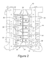
- Figure 2 is a view from underneath the engine block of Figure 1 showing the present combination bearing beam and oil management device;
- Figure 3 is a perspective view of the lower face of the combination bearing beam and oil management device shown in Fig.2;
- Figure 4 is a perspective view of the inside of the combination bearing beam and oil management device shown in Fig.3;
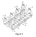
- Figure 5 is a perspective view illustrating the combination bearing beam and oil management device with a series of main bearing caps situated in the manner in which the bearing beam and bearing caps are installed in the engine;
- Figure 6 is similar to Figure 5 but shows an inside view of the combination bearing beam and oil management device;
- Figure 7 is a sectional view through a crankshaft of the engine shown in Figs 1 and 2 showing baffles and scrapers incorporated in the present device; and
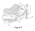
- Figure 8 illustrates a section through the crankshaft and the combination bearing beam and oil management device showing the large end of a connecting rod and the scraper and baffles incorporated in the present device.
- As shown in Figure 1, a
cylinder block 10 of an engine has bearingcap 14 mounted thereto for supporting acrankshaft 16 having acounterweight 20. A bearing beam and crankshaft-interactiveoil management device 26 is mounted to a lower surface of main bearingcap 14. The mounting ofdevice 26 is shown with further specificity in Figures 2, 5 and 6. With specific reference to Figures 5 and 6, it is noted thatmain bearing caps 14 are mounted by two inner rows of cap screws, 22 and two outer rows of cap screws, 18.Cap screws 18 are also used for the purpose of attaching or mounting bearingbeam 26 tomain bearing caps 14 andcylinder block 10. It is easily seen from Figures 5 and 6 thatcap screws 18 extend not only through bearing beam andoil management device 26, but also through the outermost mounting holes ofmain bearing caps 14 and into threaded bores (not shown) formed incylinder block 10. - As seen in Figure 2, as well as in Figures 3 and 4, combination bearing beam and
oil management device 26 has a number of laterally extending beam elements, which underliemain bearing caps 14. Thebeam elements 34 help to strengthen theengine block 10 torsionally while the longitudinal rigidity is imparted by longitudinally extendingbeam elements 30, which are shown in Figures 2, 3 and 4, as well as in Figures 5 and 6. - The
beam elements beam elements - The avoidance of unwanted noise and vibration is only part of the function of bearing beam and
oil management device 26. As shown in Figures 3, 4 and 5, a number ofwindows device 26, thewindows 54 cooperate withcounterweight scrapers 42, as shown in Figure 7, to direct oil captured byscrapers 42 into a crankcase sump which underliescylinder block 10. - In Figure 8, a
large end 24 of connectingrod 25 is shown in proximity towindow 58 formed inbearing beam 26. Thewindow 58 cooperates with connectingrod baffle 46 and connectingrod scraper 50 to remove oil from thelarge end 24 of the connecting rod and to direct the oil into the engine's sump. A plurality ofbaffle members baffle members scrapers crankshaft 16 and its connectingrods 25. - Figures 2, 3, 4 and 5 show a number of
separator elements 62 which minimize direct contact between oil within the crankcase sump and thecrankshaft 16. As described above avoiding such contact is important to prevent windage or the unwanted interaction between oil vapour, mist and liquid splashed within the crankcase sump and onto the rotatingcrankshaft 16. In this manner, the engine horsepower output will be increased and unwanted aeration of the oil which is sometimes accompanied by a loss of lubrication effectiveness, will also be avoided. - Therefore the present device provides not only longitudinal and torsional strengthening of the cylinder block by connecting the main bearing caps, but also provides the additional advantage of separating oil from the rotating assembly, including both the crankshaft counterweights and the large ends of the connecting rods, while also avoiding direct contact between oil contained within the crankcase sump and the rotating crankshaft.
- It will be appreciated by those skilled in the art that although the invention has been described by way of example with reference to one or more embodiments it is not limited to the disclosed embodiments and that one or more modifications to the disclosed embodiments or alternative embodiments could be constructed without departing from the scope of the invention as set forth in the appended claims.
Claims (10)
- A combination bearing beam and crankshaft-interactive oil management device (26) for an internal combustion engine characterised in that the device (26) comprises a plurality of longitudinally extending beam elements (30) fastened to a plurality of main bearing caps (14) and a plurality of laterally extending beam elements (34) formed integrally with said longitudinally extending beam elements (30), with one of said laterally extending beam elements (34) underlying each of said main bearing caps (14).
- A device as claimed in Claim 1 wherein the longitudinally extending beam elements (30) are fastened to the main bearing caps (14) by means of fasteners (18) passing through the beam elements (30) and through the main bearing caps (14) and into a cylinder block (10) of the engine.
- A device as claimed in Claim 1 or in Claim 2 further comprising a plurality of baffle members (38, 46) extending between the longitudinally and laterally extending beam elements (30, 34), with the baffle members (38, 46) defining a plurality of scrapers (42, 50) for capturing oil adhered to a rotating assembly (16).
- A device as claimed in Claim 3 wherein the rotating assembly is a crankshaft.
- A device as claimed in Claim 3 or in Claim 4 wherein the scrapers comprise a first plurality of scrapers (42) for removing oil adhering to a plurality of crankshaft counterweights (20) and a second plurality of scrapers (50) for removing oil adhering to the large ends (24) of a plurality of connecting rods (25).
- A device as claimed in any of Claims 3 to 5 further comprising a plurality of windows (54, 58) cooperating with the scrapers (42, 50) such that oil captured by the scrapers (42, 50) will flow through the windows (54, 58) and into a crankcase sump of the engine.
- A device as claimed in any of Claims 3 to 6 wherein the scrapers (42, 50) are supported in part by the laterally extending beam elements (34).
- A device as claimed in any of Claims 3 to 7 wherein the baffle members (38, 46) and the longitudinally and laterally extending beam elements (30, 34) are part of an integral assembly.
- A device as claimed in Claim 8 wherein the integral assembly is formed as a single cast metal part.
- An internal combustion engine having a cylinder block (10), a crankshaft (16), a plurality of main bearing caps (14) for mounting the crankshaft (16) within the cylinder block (10) characterised in that the engine further includes a combination bearing beam and crankshaft-interactive oil management device (26) as claimed in any of claims 1 to 9.
Applications Claiming Priority (1)
| Application Number | Priority Date | Filing Date | Title |
|---|---|---|---|
| US11/422,636 US20070283918A1 (en) | 2006-06-07 | 2006-06-07 | Combination Bearing Beam and Crankshaft-Interactive Oil Management Device for Internal Combustion Engine |
Publications (2)
| Publication Number | Publication Date |
|---|---|
| EP1865160A2 true EP1865160A2 (en) | 2007-12-12 |
| EP1865160A3 EP1865160A3 (en) | 2009-09-30 |
Family
ID=38523014
Family Applications (1)
| Application Number | Title | Priority Date | Filing Date |
|---|---|---|---|
| EP07109037A Withdrawn EP1865160A3 (en) | 2006-06-07 | 2007-05-28 | An Internal Combustion Engine |
Country Status (3)
| Country | Link |
|---|---|
| US (1) | US20070283918A1 (en) |
| EP (1) | EP1865160A3 (en) |
| CN (1) | CN101086217A (en) |
Cited By (1)
| Publication number | Priority date | Publication date | Assignee | Title |
|---|---|---|---|---|
| DE102010055189A1 (en) * | 2010-12-20 | 2012-06-21 | Volkswagen Ag | Windage tray for separating crankshaft and oil sump in combustion engine, has separation bars arranged on side facing crankshaft and running perpendicular to rotational axis of crankshaft such that crank spaces are separated by bars |
Families Citing this family (2)
| Publication number | Priority date | Publication date | Assignee | Title |
|---|---|---|---|---|
| DE102004061672A1 (en) * | 2004-12-22 | 2006-07-13 | Dr.Ing.H.C. F. Porsche Ag | Crankshaft bearing bridge for an internal combustion engine |
| DE102020112653A1 (en) * | 2020-05-11 | 2021-11-11 | Audi Aktiengesellschaft | Internal combustion engine |
Family Cites Families (18)
| Publication number | Priority date | Publication date | Assignee | Title |
|---|---|---|---|---|
| US4519348A (en) * | 1983-04-21 | 1985-05-28 | Edward Hamilton | Oil pan and windage tray for high performance engines |
| US4729352A (en) * | 1984-11-28 | 1988-03-08 | Honda Giken Kogyo Kabushiki Kaisha | Crankshaft supporting structure for multicylinder internal combustion engines |
| JPH071025B2 (en) * | 1988-04-05 | 1995-01-11 | マツダ株式会社 | Engine cylinder block reinforcement device |
| DE59202494D1 (en) * | 1991-05-25 | 1995-07-20 | Bayerische Motoren Werke Ag | Device for stiffening the crankcase of a reciprocating piston engine, in particular an internal combustion engine. |
| JP2573766Y2 (en) * | 1991-08-29 | 1998-06-04 | マツダ株式会社 | Engine lower block structure |
| DE4323220C1 (en) * | 1993-07-12 | 1994-09-22 | Porsche Ag | Device for carrying lubricating oil in an internal combustion engine |
| US5564837A (en) * | 1995-10-03 | 1996-10-15 | Ford Motor Company | Main bearing structure for internal combustion engine |
| JP3552414B2 (en) * | 1996-08-27 | 2004-08-11 | 日産自動車株式会社 | Oil pan device for internal combustion engine |
| AT407185B (en) * | 1998-06-03 | 2001-01-25 | Miba Sintermetall Ag | ALLOY CRANKCASE FOR A COMBUSTION ENGINE |
| US6810849B1 (en) * | 1999-01-25 | 2004-11-02 | Briggs & Stratton Corporation | Four-stroke internal combustion engine |
| AT408260B (en) * | 1999-03-19 | 2001-10-25 | Miba Sintermetall Ag | MOLDED PART FROM LIGHT METAL, ESPECIALLY CRANKCASE FOR A COMBUSTION ENGINE |
| IT1316226B1 (en) * | 1999-10-06 | 2003-04-03 | Daimler Chrysler Ag | OIL CONVEYING DEVICE IN THE INTERNAL COMBUSTION ENGINE OIL CUP. |
| US6308680B1 (en) * | 2000-09-21 | 2001-10-30 | General Motors Corporation | Engine block crankshaft bearings |
| KR100412841B1 (en) * | 2001-07-23 | 2003-12-31 | 현대자동차주식회사 | a ladder frame of engine |
| JP4228964B2 (en) * | 2004-03-30 | 2009-02-25 | 三菱自動車エンジニアリング株式会社 | Engine cylinder block structure |
| US20050279316A1 (en) * | 2004-06-17 | 2005-12-22 | Rice Alan E | Crankshaft oil deflector fastening apparatus |
| US20060102132A1 (en) * | 2004-11-18 | 2006-05-18 | Johnson Kevin L | Close tolerance crankshaft oil scraper |
| US7204224B2 (en) * | 2005-09-13 | 2007-04-17 | Gm Global Technology Operations, Inc. | Engine block structure |
-
2006
- 2006-06-07 US US11/422,636 patent/US20070283918A1/en not_active Abandoned
- 2006-11-03 CN CNA2006101445648A patent/CN101086217A/en active Pending
-
2007
- 2007-05-28 EP EP07109037A patent/EP1865160A3/en not_active Withdrawn
Cited By (2)
| Publication number | Priority date | Publication date | Assignee | Title |
|---|---|---|---|---|
| DE102010055189A1 (en) * | 2010-12-20 | 2012-06-21 | Volkswagen Ag | Windage tray for separating crankshaft and oil sump in combustion engine, has separation bars arranged on side facing crankshaft and running perpendicular to rotational axis of crankshaft such that crank spaces are separated by bars |
| DE102010055189B4 (en) | 2010-12-20 | 2023-11-09 | Volkswagen Aktiengesellschaft | Oil plane and combustion engine with oil plane |
Also Published As
| Publication number | Publication date |
|---|---|
| US20070283918A1 (en) | 2007-12-13 |
| CN101086217A (en) | 2007-12-12 |
| EP1865160A3 (en) | 2009-09-30 |
Similar Documents
| Publication | Publication Date | Title |
|---|---|---|
| EP2187018B1 (en) | Cover secured to engine | |
| EP1619363B1 (en) | Oil pan for internal combustion engine | |
| EP1081345A1 (en) | Balance shaft housing | |
| AU2002300113B2 (en) | Ladder Frame of an Engine | |
| US6880512B2 (en) | Balancer device for engine | |
| EP1865160A2 (en) | An Internal Combustion Engine | |
| US6530354B1 (en) | Oil pan with vertical baffles | |
| JP2005127149A (en) | Fastener and fastening method for baffle plate for oil pan | |
| US7204224B2 (en) | Engine block structure | |
| JP6426981B2 (en) | Balancer device for internal combustion engine | |
| JP2008190464A (en) | Engine | |
| EP0070007A1 (en) | Internal combustion engine with bearing beam structure | |
| EP0064457B2 (en) | Cylinder block of internal combustion engine | |
| CN115605673B (en) | internal combustion engine | |
| JP2003328719A (en) | Oil pan structure for internal combustion engine | |
| EP1826389B1 (en) | Internal Combustion Engine | |
| JPH04134172A (en) | Cylinder block reinforcing structure for four-cycle engine | |
| JP2003129815A (en) | Balancer shaft housing | |
| CN107155338B (en) | Engine block and internal combustion engine provided with the same | |
| JPH024248Y2 (en) | ||
| JPH089365Y2 (en) | Baffle plate mounting device for preventing oil agitation of internal combustion engine | |
| US20200386128A1 (en) | Structure of internal combustion engine | |
| JP2025082541A (en) | engine | |
| JP4292908B2 (en) | Engine oil suction structure with cast oil pan | |
| JPH0640338U (en) | Balance shaft device for internal combustion engine |
Legal Events
| Date | Code | Title | Description |
|---|---|---|---|
| PUAI | Public reference made under article 153(3) epc to a published international application that has entered the european phase |
Free format text: ORIGINAL CODE: 0009012 |
|
| AK | Designated contracting states |
Kind code of ref document: A2 Designated state(s): AT BE BG CH CY CZ DE DK EE ES FI FR GB GR HU IE IS IT LI LT LU LV MC MT NL PL PT RO SE SI SK TR |
|
| AX | Request for extension of the european patent |
Extension state: AL BA HR MK YU |
|
| PUAL | Search report despatched |
Free format text: ORIGINAL CODE: 0009013 |
|
| AK | Designated contracting states |
Kind code of ref document: A3 Designated state(s): AT BE BG CH CY CZ DE DK EE ES FI FR GB GR HU IE IS IT LI LT LU LV MC MT NL PL PT RO SE SI SK TR |
|
| AX | Request for extension of the european patent |
Extension state: AL BA HR MK RS |
|
| 17P | Request for examination filed |
Effective date: 20100129 |
|
| 17Q | First examination report despatched |
Effective date: 20100223 |
|
| AKX | Designation fees paid |
Designated state(s): DE GB SE |
|
| STAA | Information on the status of an ep patent application or granted ep patent |
Free format text: STATUS: THE APPLICATION IS DEEMED TO BE WITHDRAWN |
|
| 18D | Application deemed to be withdrawn |
Effective date: 20100707 |