EP1865147A1 - A method and apparatus for a downhole micro-sampler - Google Patents
A method and apparatus for a downhole micro-sampler Download PDFInfo
- Publication number
- EP1865147A1 EP1865147A1 EP07017683A EP07017683A EP1865147A1 EP 1865147 A1 EP1865147 A1 EP 1865147A1 EP 07017683 A EP07017683 A EP 07017683A EP 07017683 A EP07017683 A EP 07017683A EP 1865147 A1 EP1865147 A1 EP 1865147A1
- Authority
- EP
- European Patent Office
- Prior art keywords
- sample
- fluid
- chamber
- analysis
- downhole
- Prior art date
- Legal status (The legal status is an assumption and is not a legal conclusion. Google has not performed a legal analysis and makes no representation as to the accuracy of the status listed.)
- Ceased
Links
- 238000000034 method Methods 0.000 title claims description 24
- 239000012530 fluid Substances 0.000 claims abstract description 80
- 230000003287 optical effect Effects 0.000 claims description 29
- 230000005670 electromagnetic radiation Effects 0.000 claims description 15
- 239000000463 material Substances 0.000 claims description 11
- 230000000977 initiatory effect Effects 0.000 claims description 9
- 229910052594 sapphire Inorganic materials 0.000 claims description 8
- 239000010980 sapphire Substances 0.000 claims description 8
- 238000010521 absorption reaction Methods 0.000 claims description 5
- 238000004891 communication Methods 0.000 claims description 5
- 230000005540 biological transmission Effects 0.000 claims description 4
- 238000001228 spectrum Methods 0.000 claims description 4
- 238000004458 analytical method Methods 0.000 abstract description 45
- 230000015572 biosynthetic process Effects 0.000 abstract description 28
- 238000013528 artificial neural network Methods 0.000 abstract description 4
- 238000011109 contamination Methods 0.000 abstract description 4
- 230000002411 adverse Effects 0.000 abstract description 3
- 230000005484 gravity Effects 0.000 abstract description 2
- 238000011065 in-situ storage Methods 0.000 abstract 1
- 230000001151 other effect Effects 0.000 abstract 1
- 239000000523 sample Substances 0.000 description 90
- 238000005755 formation reaction Methods 0.000 description 27
- IJGRMHOSHXDMSA-UHFFFAOYSA-N Atomic nitrogen Chemical compound N#N IJGRMHOSHXDMSA-UHFFFAOYSA-N 0.000 description 10
- 239000007789 gas Substances 0.000 description 10
- 238000005070 sampling Methods 0.000 description 6
- 238000002834 transmittance Methods 0.000 description 6
- 239000000203 mixture Substances 0.000 description 5
- 238000001816 cooling Methods 0.000 description 4
- 229910052757 nitrogen Inorganic materials 0.000 description 4
- 238000001179 sorption measurement Methods 0.000 description 4
- XLYOFNOQVPJJNP-UHFFFAOYSA-N water Substances O XLYOFNOQVPJJNP-UHFFFAOYSA-N 0.000 description 4
- 238000006073 displacement reaction Methods 0.000 description 3
- 239000004215 Carbon black (E152) Substances 0.000 description 2
- 238000001069 Raman spectroscopy Methods 0.000 description 2
- 230000008901 benefit Effects 0.000 description 2
- 230000008021 deposition Effects 0.000 description 2
- 238000005553 drilling Methods 0.000 description 2
- 238000000605 extraction Methods 0.000 description 2
- 229930195733 hydrocarbon Natural products 0.000 description 2
- 150000002430 hydrocarbons Chemical class 0.000 description 2
- 239000007788 liquid Substances 0.000 description 2
- 238000005259 measurement Methods 0.000 description 2
- 238000005191 phase separation Methods 0.000 description 2
- 230000004044 response Effects 0.000 description 2
- 238000010183 spectrum analysis Methods 0.000 description 2
- 238000011179 visual inspection Methods 0.000 description 2
- 230000002238 attenuated effect Effects 0.000 description 1
- 238000005102 attenuated total reflection Methods 0.000 description 1
- 238000004364 calculation method Methods 0.000 description 1
- 150000001875 compounds Chemical class 0.000 description 1
- 230000006835 compression Effects 0.000 description 1
- 238000007906 compression Methods 0.000 description 1
- 239000000470 constituent Substances 0.000 description 1
- 238000010276 construction Methods 0.000 description 1
- 230000008602 contraction Effects 0.000 description 1
- 238000013461 design Methods 0.000 description 1
- 238000001514 detection method Methods 0.000 description 1
- 239000000835 fiber Substances 0.000 description 1
- 230000002706 hydrostatic effect Effects 0.000 description 1
- 239000007791 liquid phase Substances 0.000 description 1
- 238000004519 manufacturing process Methods 0.000 description 1
- 230000007246 mechanism Effects 0.000 description 1
- 238000012986 modification Methods 0.000 description 1
- 230000004048 modification Effects 0.000 description 1
- 238000012544 monitoring process Methods 0.000 description 1
- 239000003921 oil Substances 0.000 description 1
- 230000035515 penetration Effects 0.000 description 1
- 239000012071 phase Substances 0.000 description 1
- 239000002244 precipitate Substances 0.000 description 1
- 238000001556 precipitation Methods 0.000 description 1
- 230000008569 process Effects 0.000 description 1
- 238000005086 pumping Methods 0.000 description 1
- 238000010926 purge Methods 0.000 description 1
- 230000000717 retained effect Effects 0.000 description 1
- 230000003595 spectral effect Effects 0.000 description 1
- 238000004611 spectroscopical analysis Methods 0.000 description 1
- 238000012546 transfer Methods 0.000 description 1
- 230000035899 viability Effects 0.000 description 1
Images




Classifications
-
- E—FIXED CONSTRUCTIONS
- E21—EARTH OR ROCK DRILLING; MINING
- E21B—EARTH OR ROCK DRILLING; OBTAINING OIL, GAS, WATER, SOLUBLE OR MELTABLE MATERIALS OR A SLURRY OF MINERALS FROM WELLS
- E21B49/00—Testing the nature of borehole walls; Formation testing; Methods or apparatus for obtaining samples of soil or well fluids, specially adapted to earth drilling or wells
- E21B49/08—Obtaining fluid samples or testing fluids, in boreholes or wells
- E21B49/081—Obtaining fluid samples or testing fluids, in boreholes or wells with down-hole means for trapping a fluid sample
-
- G—PHYSICS
- G01—MEASURING; TESTING
- G01N—INVESTIGATING OR ANALYSING MATERIALS BY DETERMINING THEIR CHEMICAL OR PHYSICAL PROPERTIES
- G01N1/00—Sampling; Preparing specimens for investigation
- G01N1/02—Devices for withdrawing samples
- G01N1/10—Devices for withdrawing samples in the liquid or fluent state
- G01N1/14—Suction devices, e.g. pumps; Ejector devices
-
- G—PHYSICS
- G01—MEASURING; TESTING
- G01N—INVESTIGATING OR ANALYSING MATERIALS BY DETERMINING THEIR CHEMICAL OR PHYSICAL PROPERTIES
- G01N21/00—Investigating or analysing materials by the use of optical means, i.e. using sub-millimetre waves, infrared, visible or ultraviolet light
- G01N21/17—Systems in which incident light is modified in accordance with the properties of the material investigated
- G01N21/25—Colour; Spectral properties, i.e. comparison of effect of material on the light at two or more different wavelengths or wavelength bands
- G01N21/31—Investigating relative effect of material at wavelengths characteristic of specific elements or molecules, e.g. atomic absorption spectrometry
-
- G—PHYSICS
- G01—MEASURING; TESTING
- G01N—INVESTIGATING OR ANALYSING MATERIALS BY DETERMINING THEIR CHEMICAL OR PHYSICAL PROPERTIES
- G01N21/00—Investigating or analysing materials by the use of optical means, i.e. using sub-millimetre waves, infrared, visible or ultraviolet light
- G01N21/62—Systems in which the material investigated is excited whereby it emits light or causes a change in wavelength of the incident light
- G01N21/63—Systems in which the material investigated is excited whereby it emits light or causes a change in wavelength of the incident light optically excited
- G01N21/65—Raman scattering
-
- G—PHYSICS
- G01—MEASURING; TESTING
- G01N—INVESTIGATING OR ANALYSING MATERIALS BY DETERMINING THEIR CHEMICAL OR PHYSICAL PROPERTIES
- G01N33/00—Investigating or analysing materials by specific methods not covered by groups G01N1/00 - G01N31/00
- G01N33/26—Oils; Viscous liquids; Paints; Inks
- G01N33/28—Oils, i.e. hydrocarbon liquids
- G01N33/2823—Raw oil, drilling fluid or polyphasic mixtures
-
- G—PHYSICS
- G01—MEASURING; TESTING
- G01V—GEOPHYSICS; GRAVITATIONAL MEASUREMENTS; DETECTING MASSES OR OBJECTS; TAGS
- G01V8/00—Prospecting or detecting by optical means
- G01V8/02—Prospecting
Definitions
- the present invention relates generally to the field of downhole sampling analysis and in particular to a sample tank having a window or an internal light source for introduction of electromagnetic energy into a confined fluid sample. There response to the introduction of electromagnetic energy into the tank is used to perform non-invasive analysis of a sample in the tank without opening the tank or otherwise disturbing the sample.
- Earth formation fluids in a hydrocarbon producing well typically comprise a mixture of oil, gas, and water.
- the pressure, temperature and volume of formation fluids control the phase relation of these constituents.
- high well fluid pressures often entrain gas within the oil above the bubble point pressure.
- the pressure is reduced, the entrained or dissolved gaseous compounds separate from the liquid phase sample.
- the accurate measurement of pressure, temperature, and formation fluid composition from a particular well affects the commercial viability for producing fluids available from the well.
- the data also provides information regarding procedures for maximizing the completion and production of the respective hydrocarbon reservoir.
- United States Patent No. 6,467,544 to Brown, et al. describes a sample chamber having a slidably disposed piston to define a sample cavity on one side of the piston and a buffer cavity on the other side of the piston.
- United States Patent No. 5,361,839 to Griffith et al. (1993 ) disclosed a transducer for generating an output representative of fluid sample characteristics downhole in a wellbore.
- United States Patent No. 5,329,811 to Schultz et al. (1994 ) disclosed an apparatus and method for assessing pressure and volume data for a downhole well fluid sample.
- United States Patent No. 4,583,595 to Czenichow et al. (1986 ) disclosed a piston actuated mechanism for capturing a well fluid sample.
- United States Patent No. 4,721,157 to Berzin (1988) disclosed a shifting valve sleeve for capturing a well fluid sample in a chamber.
- United States Patent No. 4,766,955 to Petermann (1988 ) disclosed a piston engaged with a control valve for capturing a well fluid sample
- United States Patent No. 4,903,765 to Zunkel (1990 ) disclosed a time-delayed well fluid sampler.
- Temperatures downhole in a deep wellbore often exceed 300 degrees F.
- the resulting drop in temperature causes the formation fluid sample to contract. If the volume of the sample is unchanged, such contraction substantially reduces the sample pressure.
- a pressure drop causes changes in the situ formation fluid parameters, and can permit phase separation between liquids and gases entrained within the formation fluid sample. Phase separation significantly changes the formation fluid characteristics, and reduces the ability to evaluate the actual properties of the formation fluid.
- United States Patent No. 6,437,326 discloses a pre-characterising part of an apparatus for estimating an initial property of a down hole fluid, the apparatus comprising: a source of electromagnetic radiation; a chamber for containing a fluid, the chamber being transmissive of the electromagnetic radiation; and an optical analyser associated with the chamber and arranged to be in electromagnetic communication with a fluid contained therein.
- an apparatus for estimating an initial property of a down hole fluid comprising: a source of electromagnetic radiation; a chamber for containing a fluid, the chamber being transmissive of the electromagnetic radiation; and an optical analyser associated with the chamber and arranged to be in electromagnetic communication with a fluid contained therein, characterised in that the optical analyser chosen from the set consisting of an optical spectrometer, and an absorption analyser.
- the present invention addresses the shortcomings of the related art described above.
- the present invention provides a downhole sample tank having at least one window for introduction of visible, near-infrared (NIR), mid-infrared (MIR) and other electromagnetic energy into the tank for samples collected in the sample tank downhole from an earth boring or well bore.
- NIR near-infrared
- MIR mid-infrared
- the window is made of sapphire or another material capable of allowing electromagnetic energy to pass through the window.
- the entire sample tank can be made of sapphire or another material capable of allowing electromagnetic energy to pass another material enabling visual inspection or analysis of the sample inside the sample chamber.
- the present invention also provides interior NIR/MIR light sources and sensors that communicate from inside of the sample tank via electronic data signals. NIR, MIR and visible light analysis (transmittance, reflectance and absorption) is performed on the sample via the window to provide a non-invasive analysis of sample properties and contamination level.
- a single window transmits light reflected off a reflective surface inside of the sample tank to obtain transmittance data through a single window.
- a method for estimating an initial property of a fluid downhole comprising: containing a fluid downhole in a chamber; passing electromagnetic energy into the fluid through a wall of the chamber; measuring electromagnetic radiation from the fluid to estimate the initial property; and analysing spectra of the electromagnetic radiation from the fluid, charcaterised in that analysing spectra of the electromagnetic radiation from the fluid uses at least one of the set consisting of an optical spectrometer, and an absorption spectrometer.
- the surface and downhole analysis comprises determination of gas oil ratio, API gravity and various other physical parameters associated with the sample which can be calculated or estimated by a trained neural network or chemometric equation.
- a flexural mechanical or piezoelectric resonator is also provided to estimate fluid density and viscosity from which additional parameters can be estimated by a trained neural network, non linear least squares fit, chemometric equation or other soft modelling techniques well appreciated in the art.
- the sample tank is over pressurized above the bubble point for the sample to prevent adverse pressure drop. When very high pressures are desired the sample is supercharged with a pressurization gas charge.
- the downhole sample tank comprises a housing having a hollow interior and at least one window, a fiber optics lead, optical conduit or internal light source or sensor for introduction and detection of electromagnetic energy into the sample tank.
- FIG. 1 schematically represents a cross-section of earth 10 along the length of a wellbore penetration 11.
- the wellbore will be at least partially filled with a mixture of liquids including water, drilling fluid, and formation fluids that are indigenous to the earth formations penetrated by the wellbore.
- wellbore fluids such fluid mixtures are referred to as "wellbore fluids”.
- formation fluid hereinafter refers to a specific formation fluid exclusive of any substantial mixture or contamination by fluids not naturally present in the specific formation.
- a formation fluid sampling tool 20 Suspended within the wellbore 11 at the bottom end of a wireline 12 is a formation fluid sampling tool 20 .
- the wireline 12 is often carried over a pulley 13 supported by a derrick 14. Wireline deployment and retrieval is performed by a powered winch carried by a service truck 15, for example.
- FIG. 2 an exemplary embodiment of a sampling tool 20 is schematically illustrated by FIG. 2.
- the sampling tools comprise a serial assembly of several tool segments that are joined end-to-end by the threaded sleeves of mutual compression unions 23.
- An assembly of tool segments appropriate for the present invention may include a hydraulic power unit 21 and a formation fluid extractor 23. Below the extractor 23, a large displacement volume motor/pump unit 24 is provided for line purging. Below the large volume pump is a similar motor/pump unit 25 having a smaller displacement volume that is quantitatively monitored as described more expansively with respect to FIG. 3. Ordinarily, one or more sample tank magazine sections 26 are assembled below the small volume pump. Each magazine section 26 may have three or more fluid sample tanks 30.
- the formation fluid extractor 22 comprises an extensible suction probe 27 that is opposed by bore wall feet 28. Both, the suction probe 27 and the opposing feet 28 are hydraulically extensible to firmly engage the wellbore walls. Construction and operational details of the fluid extraction tool 22 are more expansively described by U.S. Patent No. 5,303,775 , the specification of which is incorporated herewith.
- an advanced optical analyzer (AOA) 800 which comprises a sample tank 816 having an integral analytical top sub 818.
- the sample 821 in the sample tank can be pressurized by the pressurized compensation system which comprises a pressure compensation system 810, having a nitrogen pressure chamber 812.
- the nitrogen pressure is available when very high pressure is desired. Pressure is applied sufficient to keep a down hole fluid sample 821 in chamber 816 above the bubble point pressure and above the pressure at which asphaltenes precipitate out of the sample.
- the AOA is also suitable for downhole capture, pressurization and analysis of gas captured in a sample 821 confined in chamber 816.
- the present example of the AOA top sub 818 provides one or more optical conduits, which in this example are high-pressure sapphire windows 814 for ingress and egress of electromagnetic energy into the analysis chamber 800 optical analysis of parameters of interest for formation fluid sample 821.
- the entire AOA including the analysis chamber can be made of sapphire or another material which enables electromagnetic energy to pass through the material, thereby enabling visual inspection and noninvasive spectral and other analysis of the contents of the AOA, including the sample chamber.
- Optical conduits other than a sapphire window are acceptable.
- An analysis module 738 comprising a light source, light sensor and processor is provided which can be used for analysis of the sample 821 down hole or at the surface.
- Analysis module 738 is in contact with the sample 821 in sample region 823 for transmission and reception of NIR/MIR light into and through the sample in region 823.
- the light reflected, fluoresced and transmitted NIR/MIR light is analyzed for transmittance, reflectance and luminance by the processor in analysis module 738.
- a flexural mechanical resonator 840 connected to analysis module 738 by communication line 741 is also provided to determine fluid viscosity, density and other parameters of interest for the fluid sample using soft modeling techniques.
- the AOA 800 is removed from a sample tank carrier and the sample 821 pressure is stabilized by pumping pressurized water 920 behind the piston 921 using pump 910. At this time the nitrogen can be released and the nitrogen chamber can be detached from the sample chamber.
- An external optical analyzer 930 or analysis module 738 comprising an NIR/MIR ultraviolet or visible light source and spectrometers provided for surfaces or down hole non-invasive analysis.
- the optical analyzer 930 is connected to a NIR/MIR light source 832 and a NIR/MIR light sensor 833 for analysis of light transmittance, fluorescence and total attenuated reflectance. That is, without disturbing the fluid sample or requiting transferring the sample to another Department of Transportation (DOT) approved chamber for transport to an off-site laboratory for analysis.
- DOT Department of Transportation
- the external optical analyzer 930 or internal analyzer 738 in the current example uses wavelength ranges from 1500 nm to 2000 nm to scan the fluid sample to determine or estimate through soft modeling techniques, parameters of interest, such as sample contamination percentage, gas oil ratio (GOR), density and asphaltene deposition pressure.
- a tunable diode laser and a Raman spectrometer are also provided in analysis module 738 for spectral analysis of the fluid sample.
- Each of the light sources and sensors are located inside of the sample tank 816 or communicate with the interior of the sample tank via the optical window 814 or an equivalent optical conduit providing data or electromagnetic energy ingress and egress to the interior of the sample tank and the sample retained therein.
- the analysis module 738 is attached as an integral part of the sample tank in the AOA prior to going down hole.
- the analysis module is used to perform NIR/MIR and other analysis described herein downhole during a run or at the surface upon completion of a sampling run downhole.
- An advantage for the disclosed method and apparatus is that no sample transfer is required, as non-invasive surface or down hole equipment in both the analysis module 738 and external equipment 830 perform PVT and spectral analysis to determine asphaltene deposition, bubble point, formation volume factor, compositional analysis and additional analysis described herein.
- FIG. 8 an alternative embodiment of the present invention is presented showing top sub 818 containing analysis module 738 attached to sample chamber 1210 pressurized by nitrogen (N 2 ) 1212 and hydrostatic pressure 1214 while down hole.
- N 2 nitrogen
- the present invention can perform sampling and sample analysis while down hole or at the surface as shown in FIG. 4, 5 and 8.
- FIG. 9 an alternative embodiment is shown wherein an internal light source 830 and an internal sensor 833 are provided for noninvasive optical analysis of the sample 821 .
- the internal processor embedded in analysis module 738 , an external analyzer 930 or a surface analyzer in surface truck 15 process the optical data to determine a parameter of interest for the fluid sample 821 .
- a ball 1301 is held in place by magnet 1317 and released in fluid sample contained in fluid sample chamber 1210.
- the ball is sensed by magnetic sensor 1319 upon arrival at point 1319 .
- the processor determines the amount of time it takes for ball 1301 to travel between point 1317 and point 1319 and determines the fluid viscosity therefrom.
- analysis window unit comprises analysis module 738 , tunable diode laser spectrometer 1415 or other optical spectrometer and sorption cooling unit 1416.
- Sorption cooling unit 1416 is described in co-owned patent application serial number 09/756,764 filed on January 8, 2001 entitled Downhole Sorption Cooling in Wireline Logging and Monitoring While Drilling" by Rocco DiFoggio, incorporated herein by reference in its entirety.
- the tunable diode laser 1415 spectrometer enable the ultra high resolution spectroscopy downhole or at the surface.
- Sorption cooling unit 1416 cools the tunable diode laser as necessary to obviate the adverse affects of downhole temperatures.
- FIG. 11 an alternative embodiment of the present invention is shown providing an external window unit 1510 for surface or downhole attachment of analysis equipment such as gas chromatographs or other analysis equipment.
- FIG. 12 is an illustration of an alternative embodiment having a single optical conduit 814, in this example a sapphire window 814 for ingress and egress of electromagnetic energy into and out of the sample chamber 816.
- Light from light source/sensor 832 enter the sample chamber 816 through single optical window 814. The light travels through the sample and bounces off of reflective surface 815.
- the round trip transmittance can determined from reflection and return of electromagnetic energy. Transmittance is determined for round trip travel of the light through the optical conduit, through the sample, reflected off of the reflective surface, returned through the sample and back through the optical conduit for measurement. Attenuated total reflectance and fluorescence response data are also sensed but do not use the reflective surface 815.
- the data is processed by processor in analysis module 738, internal analyzer/processor 930 or surface truck/controller/processor 15.
- the method and apparatus of the present invention is implemented as a set computer executable of instructions on a computer readable medium, comprising ROM, RAM, CD-ROM, Flash RAM or any other computer readable medium, now known or unknown that when executed cause a computer to implement the functions of the present invention.
Landscapes
- Life Sciences & Earth Sciences (AREA)
- Physics & Mathematics (AREA)
- Health & Medical Sciences (AREA)
- Engineering & Computer Science (AREA)
- Chemical & Material Sciences (AREA)
- General Physics & Mathematics (AREA)
- Biochemistry (AREA)
- General Health & Medical Sciences (AREA)
- Analytical Chemistry (AREA)
- Immunology (AREA)
- Pathology (AREA)
- Mining & Mineral Resources (AREA)
- Geology (AREA)
- General Life Sciences & Earth Sciences (AREA)
- Spectroscopy & Molecular Physics (AREA)
- Environmental & Geological Engineering (AREA)
- Fluid Mechanics (AREA)
- Geochemistry & Mineralogy (AREA)
- Food Science & Technology (AREA)
- Medicinal Chemistry (AREA)
- Hydrology & Water Resources (AREA)
- Oil, Petroleum & Natural Gas (AREA)
- General Chemical & Material Sciences (AREA)
- Geophysics (AREA)
- Chemical Kinetics & Catalysis (AREA)
- Nuclear Medicine, Radiotherapy & Molecular Imaging (AREA)
- Investigating Or Analysing Materials By Optical Means (AREA)
Abstract
Description
- The present invention relates generally to the field of downhole sampling analysis and in particular to a sample tank having a window or an internal light source for introduction of electromagnetic energy into a confined fluid sample. There response to the introduction of electromagnetic energy into the tank is used to perform non-invasive analysis of a sample in the tank without opening the tank or otherwise disturbing the sample.
- Earth formation fluids in a hydrocarbon producing well typically comprise a mixture of oil, gas, and water. The pressure, temperature and volume of formation fluids control the phase relation of these constituents. In a subsurface formation, high well fluid pressures often entrain gas within the oil above the bubble point pressure. When the pressure is reduced, the entrained or dissolved gaseous compounds separate from the liquid phase sample. The accurate measurement of pressure, temperature, and formation fluid composition from a particular well affects the commercial viability for producing fluids available from the well. The data also provides information regarding procedures for maximizing the completion and production of the respective hydrocarbon reservoir.
- Certain techniques analyze the well fluids downhole in the well bore.
United States Patent No. 6,467,544 to Brown, et al. describes a sample chamber having a slidably disposed piston to define a sample cavity on one side of the piston and a buffer cavity on the other side of the piston.United States Patent No. 5,361,839 to Griffith et al. (1993 ) disclosed a transducer for generating an output representative of fluid sample characteristics downhole in a wellbore.United States Patent No. 5,329,811 to Schultz et al. (1994 ) disclosed an apparatus and method for assessing pressure and volume data for a downhole well fluid sample. - Other techniques capture a well fluid sample for retrieval to the surface.
United States Patent No. 4,583,595 to Czenichow et al. (1986 ) disclosed a piston actuated mechanism for capturing a well fluid sample.United States Patent No. 4,721,157 to Berzin (1988) disclosed a shifting valve sleeve for capturing a well fluid sample in a chamber.United States Patent No. 4,766,955 to Petermann (1988 ) disclosed a piston engaged with a control valve for capturing a well fluid sample, andUnited States Patent No. 4,903,765 to Zunkel (1990 ) disclosed a time-delayed well fluid sampler.United States Patent No. 5,009,100 to Gruber et al. (1991 ) disclosed a wireline sampler for collecting a well fluid sample from a selected wellbore depth.United States Patent No. 5,240,072 to Schultz et al. (1993 ) disclosed a multiple sample annulus pressure responsive sampler for permitting well fluid sample collection at different time and depth intervals, andUnited States Patent No. 5,322,120 to Be et al. (1994 ) disclosed an electrically actuated hydraulic system for collecting well fluid samples deep in a wellbore. - Temperatures downhole in a deep wellbore often exceed 300 degrees F. When a hot formation fluid sample is retrieved to the surface at 70 degrees F, the resulting drop in temperature causes the formation fluid sample to contract. If the volume of the sample is unchanged, such contraction substantially reduces the sample pressure. A pressure drop causes changes in the situ formation fluid parameters, and can permit phase separation between liquids and gases entrained within the formation fluid sample. Phase separation significantly changes the formation fluid characteristics, and reduces the ability to evaluate the actual properties of the formation fluid.
- To overcome this limitation, various techniques have been developed to maintain pressure of the formation fluid sample.
United States Patent No. 5,337,822 to Massie et al. (1994 ) pressurized a formation fluid sample with a hydraulically driven piston powered by a high-pressure gas. Similarly,United States Patent No. 5,662,166 to Shammai (1997 ) used a pressurized gas to charge the formation fluid sample.United States Patent Nos. 5,303,775 (1994 ) and5,377,755 (1995) to Michaels et al. disclosed a bi-directional, positive displacement pump for increasing the formation fluid sample pressure below the bubble point. - Typically, sample tanks are transported to laboratories for analysis for determination of formation fluid properties based on the sample. The samples typically have to be transferred to a transportation tank, thus risking sample damage and spoilage due to pressure loss and formation of bubbles or asphaltene precipitation within the sample. Thus there is a need for a rapid sample analysis system that provides accurate results and eliminates the risk of sample spoilage.
United States Patent No. 6,437,326 discloses a pre-characterising part of an apparatus for estimating an initial property of a down hole fluid, the apparatus comprising: a source of electromagnetic radiation; a chamber for containing a fluid, the chamber being transmissive of the electromagnetic radiation; and an optical analyser associated with the chamber and arranged to be in electromagnetic communication with a fluid contained therein. - According to one aspect of the present invention, there is provided an apparatus for estimating an initial property of a down hole fluid, the apparatus comprising: a source of electromagnetic radiation; a chamber for containing a fluid, the chamber being transmissive of the electromagnetic radiation; and an optical analyser associated with the chamber and arranged to be in electromagnetic communication with a fluid contained therein, characterised in that the optical analyser chosen from the set consisting of an optical spectrometer, and an absorption analyser.
The present invention addresses the shortcomings of the related art described above. The present invention provides a downhole sample tank having at least one window for introduction of visible, near-infrared (NIR), mid-infrared (MIR) and other electromagnetic energy into the tank for samples collected in the sample tank downhole from an earth boring or well bore. The window is made of sapphire or another material capable of allowing electromagnetic energy to pass through the window. The entire sample tank can be made of sapphire or another material capable of allowing electromagnetic energy to pass another material enabling visual inspection or analysis of the sample inside the sample chamber. The present invention also provides interior NIR/MIR light sources and sensors that communicate from inside of the sample tank via electronic data signals. NIR, MIR and visible light analysis (transmittance, reflectance and absorption) is performed on the sample via the window to provide a non-invasive analysis of sample properties and contamination level. A single window transmits light reflected off a reflective surface inside of the sample tank to obtain transmittance data through a single window. - According to another aspect of the present invention, there is provided a method for estimating an initial property of a fluid downhole comprising: containing a fluid downhole in a chamber; passing electromagnetic energy into the fluid through a wall of the chamber; measuring electromagnetic radiation from the fluid to estimate the initial property; and analysing spectra of the electromagnetic radiation from the fluid, charcaterised in that analysing spectra of the electromagnetic radiation from the fluid uses at least one of the set consisting of an optical spectrometer, and an absorption spectrometer.
The surface and downhole analysis comprises determination of gas oil ratio, API gravity and various other physical parameters associated with the sample which can be calculated or estimated by a trained neural network or chemometric equation. A flexural mechanical or piezoelectric resonator is also provided to estimate fluid density and viscosity from which additional parameters can be estimated by a trained neural network, non linear least squares fit, chemometric equation or other soft modelling techniques well appreciated in the art. The sample tank is over pressurized above the bubble point for the sample to prevent adverse pressure drop. When very high pressures are desired the sample is supercharged with a pressurization gas charge. The downhole sample tank comprises a housing having a hollow interior and at least one window, a fiber optics lead, optical conduit or internal light source or sensor for introduction and detection of electromagnetic energy into the sample tank. - For detailed understanding of the present invention, references should be made to the following detailed description of the preferred embodiment, taken in conjunction with the accompanying drawings, in which like elements have been given like numerals, wherein:
- FIG. 1 is a schematic earth section illustrating the invention operating environment;
- FIG. 2 is a schematic of the invention in operative assembly with cooperatively supporting tools;
- FIG. 3 is a schematic of a representative formation fluid extraction and delivery system;
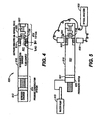
- FIG. 4 is an illustration of a preferred sample chamber and analysis top sub;
- FIG. 5 is an illustration of an alternative embodiment having a water pump to pressurize a sample for analysis by an external unit;
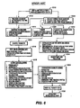
- FIG. 6 is an illustration of a common current analysis procedure;
- FIG. 7 is an illustration of the new improved procedure provided by the present invention;
- FIG. 8 is an illustration of an alternative embodiment;
- FIG. 9 is an illustration of an alternative embodiment having an internal light source and sensor;
- FIG. 10 is an illustration of an alternative embodiment having a single window and a reflective surface for return of electromagnetic radiation;
- FIG. 11 is an illustration of another alternative embodiment using a Raman spectrometer, and
- FIG. 12 is an illustration of another alternative embodiment using an external analysis equipment and at least one optical window.
- FIG. 1 schematically represents a cross-section of
earth 10 along the length of awellbore penetration 11. Usually, the wellbore will be at least partially filled with a mixture of liquids including water, drilling fluid, and formation fluids that are indigenous to the earth formations penetrated by the wellbore. Hereinafter, such fluid mixtures are referred to as "wellbore fluids". The term "formation fluid" hereinafter refers to a specific formation fluid exclusive of any substantial mixture or contamination by fluids not naturally present in the specific formation. - Suspended within the
wellbore 11 at the bottom end of awireline 12 is a formationfluid sampling tool 20. Thewireline 12 is often carried over apulley 13 supported by aderrick 14. Wireline deployment and retrieval is performed by a powered winch carried by aservice truck 15, for example. - Pursuant to the present invention, an exemplary embodiment of a
sampling tool 20 is schematically illustrated by FIG. 2. In the present example, the sampling tools comprise a serial assembly of several tool segments that are joined end-to-end by the threaded sleeves ofmutual compression unions 23. An assembly of tool segments appropriate for the present invention may include ahydraulic power unit 21 and aformation fluid extractor 23. Below theextractor 23, a large displacement volume motor/pump unit 24 is provided for line purging. Below the large volume pump is a similar motor/pump unit 25 having a smaller displacement volume that is quantitatively monitored as described more expansively with respect to FIG. 3. Ordinarily, one or more sampletank magazine sections 26 are assembled below the small volume pump. Eachmagazine section 26 may have three or morefluid sample tanks 30. - The
formation fluid extractor 22 comprises anextensible suction probe 27 that is opposed bybore wall feet 28. Both, thesuction probe 27 and the opposingfeet 28 are hydraulically extensible to firmly engage the wellbore walls. Construction and operational details of thefluid extraction tool 22 are more expansively described byU.S. Patent No. 5,303,775 , the specification of which is incorporated herewith. - Turning now to FIG. 4, in an exemplary embodiment of the present invention, an advanced optical analyzer (AOA) 800 is provided which comprises a
sample tank 816 having an integral analyticaltop sub 818. Thesample 821 in the sample tank can be pressurized by the pressurized compensation system which comprises apressure compensation system 810, having anitrogen pressure chamber 812. The nitrogen pressure is available when very high pressure is desired. Pressure is applied sufficient to keep a downhole fluid sample 821 inchamber 816 above the bubble point pressure and above the pressure at which asphaltenes precipitate out of the sample. The AOA is also suitable for downhole capture, pressurization and analysis of gas captured in asample 821 confined inchamber 816. - The present example of the
AOA top sub 818 provides one or more optical conduits, which in this example are high-pressure sapphire windows 814 for ingress and egress of electromagnetic energy into theanalysis chamber 800 optical analysis of parameters of interest forformation fluid sample 821. The entire AOA including the analysis chamber can be made of sapphire or another material which enables electromagnetic energy to pass through the material, thereby enabling visual inspection and noninvasive spectral and other analysis of the contents of the AOA, including the sample chamber. Optical conduits other than a sapphire window are acceptable. Ananalysis module 738 comprising a light source, light sensor and processor is provided which can be used for analysis of thesample 821 down hole or at the surface.Analysis module 738 is in contact with thesample 821 insample region 823 for transmission and reception of NIR/MIR light into and through the sample inregion 823. The light reflected, fluoresced and transmitted NIR/MIR light is analyzed for transmittance, reflectance and luminance by the processor inanalysis module 738. A flexuralmechanical resonator 840 connected toanalysis module 738 by communication line 741 is also provided to determine fluid viscosity, density and other parameters of interest for the fluid sample using soft modeling techniques.. - In surface operations, as shown in FIG. 5, the
AOA 800 is removed from a sample tank carrier and thesample 821 pressure is stabilized by pumpingpressurized water 920 behind thepiston 921 usingpump 910. At this time the nitrogen can be released and the nitrogen chamber can be detached from the sample chamber. An externaloptical analyzer 930 oranalysis module 738 comprising an NIR/MIR ultraviolet or visible light source and spectrometers provided for surfaces or down hole non-invasive analysis. Theoptical analyzer 930 is connected to a NIR/MIRlight source 832 and a NIR/MIR light sensor 833 for analysis of light transmittance, fluorescence and total attenuated reflectance. That is, without disturbing the fluid sample or requiting transferring the sample to another Department of Transportation (DOT) approved chamber for transport to an off-site laboratory for analysis. - The external
optical analyzer 930 orinternal analyzer 738 in the current example uses wavelength ranges from 1500 nm to 2000 nm to scan the fluid sample to determine or estimate through soft modeling techniques, parameters of interest, such as sample contamination percentage, gas oil ratio (GOR), density and asphaltene deposition pressure. A tunable diode laser and a Raman spectrometer are also provided inanalysis module 738 for spectral analysis of the fluid sample. Each of the light sources and sensors are located inside of thesample tank 816 or communicate with the interior of the sample tank via theoptical window 814 or an equivalent optical conduit providing data or electromagnetic energy ingress and egress to the interior of the sample tank and the sample retained therein. - The
analysis module 738 is attached as an integral part of the sample tank in the AOA prior to going down hole. The analysis module is used to perform NIR/MIR and other analysis described herein downhole during a run or at the surface upon completion of a sampling run downhole. Some of the numerous advantages of the AOA of the present invention are shown by comparison to FIG. 6, a prior art system and FIG. 7, the new method and apparatus design provided by the AOA of the present invention. Note that in FIG. 7 that a primary parameter calculation byoptical techniques 1114 is available immediately or in less than six hours and afinal PVT report 1132 in less than a week or less rather than six to eight weeks as shown in FIG. 6 for the prior art system. An advantage for the disclosed method and apparatus is that no sample transfer is required, as non-invasive surface or down hole equipment in both theanalysis module 738 andexternal equipment 830 perform PVT and spectral analysis to determine asphaltene deposition, bubble point, formation volume factor, compositional analysis and additional analysis described herein. - Turning now to FIG. 8 an alternative embodiment of the present invention is presented showing
top sub 818 containinganalysis module 738 attached to samplechamber 1210 pressurized by nitrogen (N2) 1212 andhydrostatic pressure 1214 while down hole. Thus, the present invention can perform sampling and sample analysis while down hole or at the surface as shown in FIG. 4, 5 and 8. - Turning now to FIG. 9, an alternative embodiment is shown wherein an internal
light source 830 and aninternal sensor 833 are provided for noninvasive optical analysis of thesample 821. The internal processor embedded inanalysis module 738, anexternal analyzer 930 or a surface analyzer insurface truck 15 process the optical data to determine a parameter of interest for thefluid sample 821. As shown in FIG 9, to determine viscosity a ball 1301 is held in place by magnet 1317 and released in fluid sample contained influid sample chamber 1210. The ball is sensed by magnetic sensor 1319 upon arrival at point 1319. The processor determines the amount of time it takes for ball 1301 to travel between point 1317 and point 1319 and determines the fluid viscosity therefrom. - As shown in FIG. 10, analysis window unit comprises
analysis module 738, tunablediode laser spectrometer 1415 or other optical spectrometer andsorption cooling unit 1416.Sorption cooling unit 1416 is described in co-owned patent application serial number09/756,764 filed on January 8, 2001 - The
tunable diode laser 1415 spectrometer enable the ultra high resolution spectroscopy downhole or at the surface.Sorption cooling unit 1416 cools the tunable diode laser as necessary to obviate the adverse affects of downhole temperatures. - Turning now the FIG. 11, an alternative embodiment of the present invention is shown providing an
external window unit 1510 for surface or downhole attachment of analysis equipment such as gas chromatographs or other analysis equipment. - FIG. 12 is an illustration of an alternative embodiment having a single
optical conduit 814, in this example asapphire window 814 for ingress and egress of electromagnetic energy into and out of thesample chamber 816. Light from light source/sensor 832 enter thesample chamber 816 through singleoptical window 814. The light travels through the sample and bounces off of reflective surface 815. Thus, the round trip transmittance can determined from reflection and return of electromagnetic energy. Transmittance is determined for round trip travel of the light through the optical conduit, through the sample, reflected off of the reflective surface, returned through the sample and back through the optical conduit for measurement. Attenuated total reflectance and fluorescence response data are also sensed but do not use the reflective surface 815. The data is processed by processor inanalysis module 738, internal analyzer/processor 930 or surface truck/controller/processor 15. - In another embodiment, the method and apparatus of the present invention is implemented as a set computer executable of instructions on a computer readable medium, comprising ROM, RAM, CD-ROM, Flash RAM or any other computer readable medium, now known or unknown that when executed cause a computer to implement the functions of the present invention.
- While the foregoing disclosure is directed to the preferred embodiments of the invention various modifications will be apparent to those skilled in the art. It is intended that all variations within the scope of the appended claims be embraced by the foregoing disclosure. Examples of the more important features of the invention have been summarized rather broadly in order that the detailed description thereof that follows may be better understood, and in order that the contributions to the art may be appreciated. There are, of course, additional features of the invention that will be described hereinafter and which will form the subject of the claims appended hereto.
Claims (13)
- An apparatus for estimating an initial property of a downhole fluid, the apparatus comprising:a source (738,832) of electromagnetic radiation;a chamber (800) for containing a fluid, the chamber (814) being transmissive of the electromagnetic radiation; andan optical analyser (738,930) associated with the chamber (814) and arranged to be in electromagnetic communication with a fluid contained thereincharacterised in that the optical analyser (738,930) chosen from the set consisting of an optical spectrometer, and an absorption analyser.
- The apparatus of claim 1, further comprising a piezoelectric resonator (840) for estimating a second property of a fluid contained in the chamber (800).
- The apparatus of claim 1, further comprising:a processor configured to perform a soft modelling technique for estimating a second property for a fluid contained in the chamber from the initial property of such a fluid.
- The apparatus of claim 1, wherein the entire chamber (800) is made of a material that allows transmission of electromagnetic energy through the material.
- The apparatus of claim 1, wherein the entire chamber (800) is made of sapphire.
- The apparatus of claim 2, further comprising:an electromagnetic radiation sensor inside the chamber; anda processor (738) to estimate the initial property based on a reading from the electromagnetic radiation sensor.
- The apparatus of claim 1, wherein the optical analyser is in electronic communication with the sensor.
- A method for estimating an initial property of a fluid downhole comprising:containing a fluid downhole in a chamber;passing electromagnetic energy into the fluid through a wall of the chamber;measuring electromagnetic radiation from the fluid to estimate the initial property; andanalysing spectra of the electromagnetic radiation from the fluid,characterised in that analysing spectra of the electromagnetic radiation from the fluid uses at least one of the set consisting of an optical spectrometer, and an absorption spectrometer.
- The method of claim 8, wherein the entire chamber is made of sapphire.
- The method of claim 8, wherein the analysing comprises analyzing light that passes through the chamber wall.
- The method of claim 8, wherein analysing further comprises:estimating a second property of the fluid using a piezoelectric resonator.
- The method of claim 8, wherein the entire chamber is made of a material that allows transmission of electromagnetic energy through the material.
- The method of claim 8, wherein the entire chamber is made of a material that allows transmission of electromagnetic energy through the material.
Priority Applications (1)
| Application Number | Priority Date | Filing Date | Title |
|---|---|---|---|
| EP10175791.2A EP2320026B1 (en) | 2003-05-02 | 2004-04-29 | A method and apparatus for a downhole micro-sampler |
Applications Claiming Priority (2)
| Application Number | Priority Date | Filing Date | Title |
|---|---|---|---|
| US46766803P | 2003-05-02 | 2003-05-02 | |
| EP04750868A EP1631732B1 (en) | 2003-05-02 | 2004-04-29 | A method and apparatus for an advanced optical analyzer |
Related Parent Applications (1)
| Application Number | Title | Priority Date | Filing Date |
|---|---|---|---|
| EP04750868A Division EP1631732B1 (en) | 2003-05-02 | 2004-04-29 | A method and apparatus for an advanced optical analyzer |
Publications (1)
| Publication Number | Publication Date |
|---|---|
| EP1865147A1 true EP1865147A1 (en) | 2007-12-12 |
Family
ID=38663272
Family Applications (1)
| Application Number | Title | Priority Date | Filing Date |
|---|---|---|---|
| EP07017683A Ceased EP1865147A1 (en) | 2003-05-02 | 2004-04-29 | A method and apparatus for a downhole micro-sampler |
Country Status (1)
| Country | Link |
|---|---|
| EP (1) | EP1865147A1 (en) |
Cited By (7)
| Publication number | Priority date | Publication date | Assignee | Title |
|---|---|---|---|---|
| WO2009068957A1 (en) * | 2007-11-29 | 2009-06-04 | Schlumberger Technology B.V. | Methods and apparatus to determine a concentration of nitrogen in a downhole fluid |
| WO2009094351A3 (en) * | 2008-01-24 | 2009-12-03 | Baker Hughes Incorporated | Apparatus and method for determining fluid properties |
| US8032311B2 (en) | 2008-05-22 | 2011-10-04 | Baker Hughes Incorporated | Estimating gas-oil ratio from other physical properties |
| EP2734829A4 (en) * | 2011-12-14 | 2015-05-06 | Halliburton Energy Services Inc | Methods of analyzing a reservoir fluid sample using a multivariate optical element calculation device |
| WO2021081174A1 (en) * | 2019-10-22 | 2021-04-29 | Schlumberger Technology Corporation | Fluid type identification from downhole fluid analysis using machine learning techniques |
| CN113484185A (en) * | 2021-07-19 | 2021-10-08 | 中国矿业大学 | Fixed-point sampling device and method for integrally measuring gas content in underground coal mine |
| EP4202408A1 (en) * | 2016-03-18 | 2023-06-28 | Baker Hughes, A Ge Company, Llc | Low etendue light source for fiber optic sensors in high temperature environments |
Citations (8)
| Publication number | Priority date | Publication date | Assignee | Title |
|---|---|---|---|---|
| US3448611A (en) * | 1966-09-29 | 1969-06-10 | Schlumberger Technology Corp | Method and apparatus for formation testing |
| EP0295923A2 (en) * | 1987-06-19 | 1988-12-21 | Halliburton Company | Well fluid sampling apparatus |
| US5166747A (en) * | 1990-06-01 | 1992-11-24 | Schlumberger Technology Corporation | Apparatus and method for analyzing the composition of formation fluids |
| US5859430A (en) * | 1997-04-10 | 1999-01-12 | Schlumberger Technology Corporation | Method and apparatus for the downhole compositional analysis of formation gases |
| US6092416A (en) * | 1997-04-16 | 2000-07-25 | Schlumberger Technology Corporation | Downholed system and method for determining formation properties |
| US6178815B1 (en) * | 1998-07-30 | 2001-01-30 | Schlumberger Technology Corporation | Method to improve the quality of a formation fluid sample |
| EP1205630A2 (en) * | 2000-11-14 | 2002-05-15 | Services Petroliers Schlumberger | Sample chamber with dead volume flushing |
| US6437326B1 (en) * | 2000-06-27 | 2002-08-20 | Schlumberger Technology Corporation | Permanent optical sensor downhole fluid analysis systems |
-
2004
- 2004-04-29 EP EP07017683A patent/EP1865147A1/en not_active Ceased
Patent Citations (8)
| Publication number | Priority date | Publication date | Assignee | Title |
|---|---|---|---|---|
| US3448611A (en) * | 1966-09-29 | 1969-06-10 | Schlumberger Technology Corp | Method and apparatus for formation testing |
| EP0295923A2 (en) * | 1987-06-19 | 1988-12-21 | Halliburton Company | Well fluid sampling apparatus |
| US5166747A (en) * | 1990-06-01 | 1992-11-24 | Schlumberger Technology Corporation | Apparatus and method for analyzing the composition of formation fluids |
| US5859430A (en) * | 1997-04-10 | 1999-01-12 | Schlumberger Technology Corporation | Method and apparatus for the downhole compositional analysis of formation gases |
| US6092416A (en) * | 1997-04-16 | 2000-07-25 | Schlumberger Technology Corporation | Downholed system and method for determining formation properties |
| US6178815B1 (en) * | 1998-07-30 | 2001-01-30 | Schlumberger Technology Corporation | Method to improve the quality of a formation fluid sample |
| US6437326B1 (en) * | 2000-06-27 | 2002-08-20 | Schlumberger Technology Corporation | Permanent optical sensor downhole fluid analysis systems |
| EP1205630A2 (en) * | 2000-11-14 | 2002-05-15 | Services Petroliers Schlumberger | Sample chamber with dead volume flushing |
Cited By (13)
| Publication number | Priority date | Publication date | Assignee | Title |
|---|---|---|---|---|
| US8032303B2 (en) | 2007-11-29 | 2011-10-04 | Schlumberger Technology Corporation | Methods and apparatus to determine a concentration of nitrogen in a downhole fluid |
| WO2009068957A1 (en) * | 2007-11-29 | 2009-06-04 | Schlumberger Technology B.V. | Methods and apparatus to determine a concentration of nitrogen in a downhole fluid |
| GB2469409B (en) * | 2008-01-24 | 2012-05-30 | Baker Hughes Inc | Apparatus and method for determining fluid properties |
| US7886821B2 (en) | 2008-01-24 | 2011-02-15 | Baker Hughes Incorporated | Apparatus and method for determining fluid properties |
| GB2469409A (en) * | 2008-01-24 | 2010-10-13 | Baker Hughes Inc | Apparatus and method for determining fluid properties |
| WO2009094351A3 (en) * | 2008-01-24 | 2009-12-03 | Baker Hughes Incorporated | Apparatus and method for determining fluid properties |
| US8032311B2 (en) | 2008-05-22 | 2011-10-04 | Baker Hughes Incorporated | Estimating gas-oil ratio from other physical properties |
| EP2734829A4 (en) * | 2011-12-14 | 2015-05-06 | Halliburton Energy Services Inc | Methods of analyzing a reservoir fluid sample using a multivariate optical element calculation device |
| EP4202408A1 (en) * | 2016-03-18 | 2023-06-28 | Baker Hughes, A Ge Company, Llc | Low etendue light source for fiber optic sensors in high temperature environments |
| WO2021081174A1 (en) * | 2019-10-22 | 2021-04-29 | Schlumberger Technology Corporation | Fluid type identification from downhole fluid analysis using machine learning techniques |
| US12146406B2 (en) | 2019-10-22 | 2024-11-19 | Schlumberger Technology Corporation | Fluid type identification from downhole fluid analysis using machine learning techniques |
| CN113484185A (en) * | 2021-07-19 | 2021-10-08 | 中国矿业大学 | Fixed-point sampling device and method for integrally measuring gas content in underground coal mine |
| CN113484185B (en) * | 2021-07-19 | 2022-04-29 | 中国矿业大学 | Fixed-point sampling device and method for integrally measuring gas content in underground coal mine |
Similar Documents
| Publication | Publication Date | Title |
|---|---|---|
| EP1631732B1 (en) | A method and apparatus for an advanced optical analyzer | |
| CA2605830C (en) | Methods and apparatus of downhole fluid analysis | |
| CA2639577C (en) | Method to measure the bubble point pressure of downhole fluid | |
| US8023690B2 (en) | Apparatus and method for imaging fluids downhole | |
| US7826050B2 (en) | System and method for dual path length optical analysis of fluids downhole | |
| EP1620631B1 (en) | Continuous data recorder for a downhole sample tank | |
| WO2000042416A1 (en) | Optical tool and method for analysis of formation fluids | |
| US20090321072A1 (en) | Methods and apparatus of downhole fluids analysis | |
| US20140352397A1 (en) | Optical Fluid Analyzer with Calibrator and Method of Using Same | |
| US7886821B2 (en) | Apparatus and method for determining fluid properties | |
| GB2391939A (en) | Method of analysing a formation fluid from a formation surrounding a wellbore having a borehole fluid | |
| US10316650B2 (en) | Gas phase detection of downhole fluid sample components |
Legal Events
| Date | Code | Title | Description |
|---|---|---|---|
| PUAI | Public reference made under article 153(3) epc to a published international application that has entered the european phase |
Free format text: ORIGINAL CODE: 0009012 |
|
| AC | Divisional application: reference to earlier application |
Ref document number: 1631732 Country of ref document: EP Kind code of ref document: P |
|
| AK | Designated contracting states |
Kind code of ref document: A1 Designated state(s): DE FR GB |
|
| 17P | Request for examination filed |
Effective date: 20080609 |
|
| 17Q | First examination report despatched |
Effective date: 20080721 |
|
| AKX | Designation fees paid |
Designated state(s): DE FR GB |
|
| STAA | Information on the status of an ep patent application or granted ep patent |
Free format text: STATUS: THE APPLICATION HAS BEEN REFUSED |
|
| 18R | Application refused |
Effective date: 20100922 |