EP1864914A1 - Container assembly having stacking means - Google Patents
Container assembly having stacking means Download PDFInfo
- Publication number
- EP1864914A1 EP1864914A1 EP07109447A EP07109447A EP1864914A1 EP 1864914 A1 EP1864914 A1 EP 1864914A1 EP 07109447 A EP07109447 A EP 07109447A EP 07109447 A EP07109447 A EP 07109447A EP 1864914 A1 EP1864914 A1 EP 1864914A1
- Authority
- EP
- European Patent Office
- Prior art keywords
- lid
- container assembly
- container
- connection portion
- cam
- Prior art date
- Legal status (The legal status is an assumption and is not a legal conclusion. Google has not performed a legal analysis and makes no representation as to the accuracy of the status listed.)
- Granted
Links
Images


Classifications
-
- B—PERFORMING OPERATIONS; TRANSPORTING
- B65—CONVEYING; PACKING; STORING; HANDLING THIN OR FILAMENTARY MATERIAL
- B65D—CONTAINERS FOR STORAGE OR TRANSPORT OF ARTICLES OR MATERIALS, e.g. BAGS, BARRELS, BOTTLES, BOXES, CANS, CARTONS, CRATES, DRUMS, JARS, TANKS, HOPPERS, FORWARDING CONTAINERS; ACCESSORIES, CLOSURES, OR FITTINGS THEREFOR; PACKAGING ELEMENTS; PACKAGES
- B65D51/00—Closures not otherwise provided for
- B65D51/24—Closures not otherwise provided for combined or co-operating with auxiliary devices for non-closing purposes
- B65D51/246—Closures not otherwise provided for combined or co-operating with auxiliary devices for non-closing purposes provided with eating utensils or spatulas
- B65D51/247—Closures not otherwise provided for combined or co-operating with auxiliary devices for non-closing purposes provided with eating utensils or spatulas located between an inner and an outer closure
-
- B—PERFORMING OPERATIONS; TRANSPORTING
- B65—CONVEYING; PACKING; STORING; HANDLING THIN OR FILAMENTARY MATERIAL
- B65D—CONTAINERS FOR STORAGE OR TRANSPORT OF ARTICLES OR MATERIALS, e.g. BAGS, BARRELS, BOTTLES, BOXES, CANS, CARTONS, CRATES, DRUMS, JARS, TANKS, HOPPERS, FORWARDING CONTAINERS; ACCESSORIES, CLOSURES, OR FITTINGS THEREFOR; PACKAGING ELEMENTS; PACKAGES
- B65D21/00—Nestable, stackable or joinable containers; Containers of variable capacity
- B65D21/02—Containers specially shaped, or provided with fittings or attachments, to facilitate nesting, stacking, or joining together
- B65D21/0209—Containers specially shaped, or provided with fittings or attachments, to facilitate nesting, stacking, or joining together stackable or joined together one-upon-the-other in the upright or upside-down position
- B65D21/0217—Containers with a closure presenting stacking elements
- B65D21/022—Containers with a closure presenting stacking elements the bottom presenting projecting peripheral elements receiving or surrounding the closure or peripheral elements projecting therefrom
-
- B—PERFORMING OPERATIONS; TRANSPORTING
- B65—CONVEYING; PACKING; STORING; HANDLING THIN OR FILAMENTARY MATERIAL
- B65D—CONTAINERS FOR STORAGE OR TRANSPORT OF ARTICLES OR MATERIALS, e.g. BAGS, BARRELS, BOTTLES, BOXES, CANS, CARTONS, CRATES, DRUMS, JARS, TANKS, HOPPERS, FORWARDING CONTAINERS; ACCESSORIES, CLOSURES, OR FITTINGS THEREFOR; PACKAGING ELEMENTS; PACKAGES
- B65D43/00—Lids or covers for rigid or semi-rigid containers
- B65D43/02—Removable lids or covers
- B65D43/0235—Removable lids or covers with integral tamper element
- B65D43/0264—Removable lids or covers with integral tamper element secured only by friction or gravity before removal of the tamper element
- B65D43/0268—Removable lids or covers with integral tamper element secured only by friction or gravity before removal of the tamper element on both the inside and the outside of the mouth of the container
-
- B—PERFORMING OPERATIONS; TRANSPORTING
- B65—CONVEYING; PACKING; STORING; HANDLING THIN OR FILAMENTARY MATERIAL
- B65D—CONTAINERS FOR STORAGE OR TRANSPORT OF ARTICLES OR MATERIALS, e.g. BAGS, BARRELS, BOTTLES, BOXES, CANS, CARTONS, CRATES, DRUMS, JARS, TANKS, HOPPERS, FORWARDING CONTAINERS; ACCESSORIES, CLOSURES, OR FITTINGS THEREFOR; PACKAGING ELEMENTS; PACKAGES
- B65D2543/00—Lids or covers essentially for box-like containers
- B65D2543/00009—Details of lids or covers for rigid or semi-rigid containers
- B65D2543/00018—Overall construction of the lid
- B65D2543/00027—Stackable lids or covers
-
- B—PERFORMING OPERATIONS; TRANSPORTING
- B65—CONVEYING; PACKING; STORING; HANDLING THIN OR FILAMENTARY MATERIAL
- B65D—CONTAINERS FOR STORAGE OR TRANSPORT OF ARTICLES OR MATERIALS, e.g. BAGS, BARRELS, BOTTLES, BOXES, CANS, CARTONS, CRATES, DRUMS, JARS, TANKS, HOPPERS, FORWARDING CONTAINERS; ACCESSORIES, CLOSURES, OR FITTINGS THEREFOR; PACKAGING ELEMENTS; PACKAGES
- B65D2543/00—Lids or covers essentially for box-like containers
- B65D2543/00009—Details of lids or covers for rigid or semi-rigid containers
- B65D2543/00018—Overall construction of the lid
- B65D2543/00064—Shape of the outer periphery
- B65D2543/0012—Shape of the outer periphery having straight sides, e.g. with curved corners
- B65D2543/00175—Shape of the outer periphery having straight sides, e.g. with curved corners four straight sides, e.g. trapezium or diamond
-
- B—PERFORMING OPERATIONS; TRANSPORTING
- B65—CONVEYING; PACKING; STORING; HANDLING THIN OR FILAMENTARY MATERIAL
- B65D—CONTAINERS FOR STORAGE OR TRANSPORT OF ARTICLES OR MATERIALS, e.g. BAGS, BARRELS, BOTTLES, BOXES, CANS, CARTONS, CRATES, DRUMS, JARS, TANKS, HOPPERS, FORWARDING CONTAINERS; ACCESSORIES, CLOSURES, OR FITTINGS THEREFOR; PACKAGING ELEMENTS; PACKAGES
- B65D2543/00—Lids or covers essentially for box-like containers
- B65D2543/00009—Details of lids or covers for rigid or semi-rigid containers
- B65D2543/00018—Overall construction of the lid
- B65D2543/00231—Overall construction of the lid made of several pieces
- B65D2543/0024—Overall construction of the lid made of several pieces two pieces, one forming at least the whole skirt, the other forming at least the whole upper part
-
- B—PERFORMING OPERATIONS; TRANSPORTING
- B65—CONVEYING; PACKING; STORING; HANDLING THIN OR FILAMENTARY MATERIAL
- B65D—CONTAINERS FOR STORAGE OR TRANSPORT OF ARTICLES OR MATERIALS, e.g. BAGS, BARRELS, BOTTLES, BOXES, CANS, CARTONS, CRATES, DRUMS, JARS, TANKS, HOPPERS, FORWARDING CONTAINERS; ACCESSORIES, CLOSURES, OR FITTINGS THEREFOR; PACKAGING ELEMENTS; PACKAGES
- B65D2543/00—Lids or covers essentially for box-like containers
- B65D2543/00009—Details of lids or covers for rigid or semi-rigid containers
- B65D2543/00018—Overall construction of the lid
- B65D2543/00259—Materials used
- B65D2543/00296—Plastic
-
- B—PERFORMING OPERATIONS; TRANSPORTING
- B65—CONVEYING; PACKING; STORING; HANDLING THIN OR FILAMENTARY MATERIAL
- B65D—CONTAINERS FOR STORAGE OR TRANSPORT OF ARTICLES OR MATERIALS, e.g. BAGS, BARRELS, BOTTLES, BOXES, CANS, CARTONS, CRATES, DRUMS, JARS, TANKS, HOPPERS, FORWARDING CONTAINERS; ACCESSORIES, CLOSURES, OR FITTINGS THEREFOR; PACKAGING ELEMENTS; PACKAGES
- B65D2543/00—Lids or covers essentially for box-like containers
- B65D2543/00009—Details of lids or covers for rigid or semi-rigid containers
- B65D2543/00342—Central part of the lid
- B65D2543/00351—Dome-like
-
- B—PERFORMING OPERATIONS; TRANSPORTING
- B65—CONVEYING; PACKING; STORING; HANDLING THIN OR FILAMENTARY MATERIAL
- B65D—CONTAINERS FOR STORAGE OR TRANSPORT OF ARTICLES OR MATERIALS, e.g. BAGS, BARRELS, BOTTLES, BOXES, CANS, CARTONS, CRATES, DRUMS, JARS, TANKS, HOPPERS, FORWARDING CONTAINERS; ACCESSORIES, CLOSURES, OR FITTINGS THEREFOR; PACKAGING ELEMENTS; PACKAGES
- B65D2543/00—Lids or covers essentially for box-like containers
- B65D2543/00009—Details of lids or covers for rigid or semi-rigid containers
- B65D2543/00444—Contact between the container and the lid
- B65D2543/00481—Contact between the container and the lid on the inside or the outside of the container
- B65D2543/0049—Contact between the container and the lid on the inside or the outside of the container on the inside, or a part turned to the inside of the mouth of the container
- B65D2543/00518—Skirt
-
- B—PERFORMING OPERATIONS; TRANSPORTING
- B65—CONVEYING; PACKING; STORING; HANDLING THIN OR FILAMENTARY MATERIAL
- B65D—CONTAINERS FOR STORAGE OR TRANSPORT OF ARTICLES OR MATERIALS, e.g. BAGS, BARRELS, BOTTLES, BOXES, CANS, CARTONS, CRATES, DRUMS, JARS, TANKS, HOPPERS, FORWARDING CONTAINERS; ACCESSORIES, CLOSURES, OR FITTINGS THEREFOR; PACKAGING ELEMENTS; PACKAGES
- B65D2543/00—Lids or covers essentially for box-like containers
- B65D2543/00009—Details of lids or covers for rigid or semi-rigid containers
- B65D2543/00444—Contact between the container and the lid
- B65D2543/00481—Contact between the container and the lid on the inside or the outside of the container
- B65D2543/00537—Contact between the container and the lid on the inside or the outside of the container on the outside, or a part turned to the outside of the mouth of the container
-
- B—PERFORMING OPERATIONS; TRANSPORTING
- B65—CONVEYING; PACKING; STORING; HANDLING THIN OR FILAMENTARY MATERIAL
- B65D—CONTAINERS FOR STORAGE OR TRANSPORT OF ARTICLES OR MATERIALS, e.g. BAGS, BARRELS, BOTTLES, BOXES, CANS, CARTONS, CRATES, DRUMS, JARS, TANKS, HOPPERS, FORWARDING CONTAINERS; ACCESSORIES, CLOSURES, OR FITTINGS THEREFOR; PACKAGING ELEMENTS; PACKAGES
- B65D2543/00—Lids or covers essentially for box-like containers
- B65D2543/00009—Details of lids or covers for rigid or semi-rigid containers
- B65D2543/00444—Contact between the container and the lid
- B65D2543/00481—Contact between the container and the lid on the inside or the outside of the container
- B65D2543/00555—Contact between the container and the lid on the inside or the outside of the container on both the inside and the outside
-
- B—PERFORMING OPERATIONS; TRANSPORTING
- B65—CONVEYING; PACKING; STORING; HANDLING THIN OR FILAMENTARY MATERIAL
- B65D—CONTAINERS FOR STORAGE OR TRANSPORT OF ARTICLES OR MATERIALS, e.g. BAGS, BARRELS, BOTTLES, BOXES, CANS, CARTONS, CRATES, DRUMS, JARS, TANKS, HOPPERS, FORWARDING CONTAINERS; ACCESSORIES, CLOSURES, OR FITTINGS THEREFOR; PACKAGING ELEMENTS; PACKAGES
- B65D2543/00—Lids or covers essentially for box-like containers
- B65D2543/00009—Details of lids or covers for rigid or semi-rigid containers
- B65D2543/00824—Means for facilitating removing of the closure
- B65D2543/00833—Integral tabs, tongues, handles or similar
- B65D2543/00842—Integral tabs, tongues, handles or similar outside of the lid
Definitions
- the present invention relates to a container assembly comprising a container part and a lid part, said lid part comprising a connection portion for connection to said container part and a lid being pivotably connected to said connection portion.
- the invention further relates to such a lid part.
- Such a container assembly and lid part are known from PCT/NL 2005/000089 , which is incorporated by reference as if fully set forth.
- a package is disclosed therein for containing both a product and a spoon.
- Subject invention can be used in combination with such a package but it should be noted that it can also be used with other prior art packages.
- Such a container assembly is produced by combining the container part with the lid part. More particular the connection portion of the lid part is adhered to the top side of the container. It is aimed to optimize the assembly of the lid part and container part as much as possible. To that end lid parts should be automatically supplied and manipulated to be brought in position on the container part. Exact positioning of the lid part is essential.
- the invention aims to improve handling of the lid parts in order to more easily assemble lid part and container part.
- Another object of the invention is to improve the handling of the container with the lid part and container part attached to it.
- Yet another object of the invention is to provide the improvements without deteriorating other beneficial properties of the container assembly.
- this is realized with a container assembly as described above in that the side remote from said lid of said connection portion and the side from the lid remote from the connection portion are provided with first complementary stacking means.
- a stable stack of lid parts is obtained by the complementary cooperating stacking means provided both on the top and lower side of each lid part.
- This provides the possibility of stacking lid parts during manufacturing in a stable and well-defined way, allowing improved automatic handling. Furthermore, as will be explained, it allows stable stacking of container assemblies on top of one another. Additionally, it allows at the same time an improved stability and rigidity of the lid and improved handling during use, in particular during opening and closing of the lid.
- complementary stacking means can comprise any structure of complementary interengaging means.
- the complementary stacking means comprise a cam-recess. The cam should be positioned in the recess after which a stable stack of lid parts is obtained. From such stable stack with a robot arm lid parts can be taken to be placed on the container part during manufacturing of the container assemblies.
- the cam can be provided both on the side of the lid facing away from the connection portion or in the connection portion. However, it is preferred that the cam is provided in the top of the lid. In this way basically the connection portion can be produced without too many special measures taken for receiving the cam of the adjacent lid part. In most cases the circumferential rim of the connection portion will be sufficient to receive the cam of the next adjacent lid.
- complementary stacking means are also provided between the top of the lid and the bottom of the container part.
- assembled (and filled) container assemblies can be stacked on top of each other during shipping and display for the consumer.
- these complementary stacking means are preferably provided such that the lid has a cam whilst the bottom of the container part is provided with a corresponding accommodation.
- accommodation is delimited by the circumferential rim of the bottom of the container which is preferably made from the outer wall of the container together with part of the bottom thereof.
- the cam on top of the lid both functions as complementary stacking means for further lid parts during assembly and as complementary stacking means during stacking of the container assemblies. In this way only a single cam will suffice.
- the cam is a circumferential cam extending near the outer circumference of the lid to provide maximum stability during stacking.
- a circumferential cam has interruptions to be able to clean the top of the lid by whipping away debris and the like.
- the complementary stacking means comprise a rim extending from the upper part of the lid (in other words, the side of the lid remote from the connection part), said rim providing a first abutment against sliding in a direction substantially in the lid's plane.
- the lid furthermore preferably has a second abutment contiguous to rim, provided by the surface of the lid adjacent to the rim.
- the container part at its bottom side has a rim, which has dimensions adapted to the dimensions of the rim on the lid in such a way so as to work together with the rim on the lid to provide complementary stacking means which prevent a first container assembly which is placed on top of a second container assembly, i.e. with its bottom on the lid of the second container, from sliding.
- connection portion at its side remote from the lid of the connection portion has a rim fur providing a first abutment in a direction substantially in the lid's plan for providing an abutment against the first abutment of the rim on the lid.
- this rim on the connection portion can have a second abutment for providing an abutment against the second abutment contiguous to rim on the lid, i.e. the second abutment provided by the surface of the lid adjacent the rim.
- this rim on the connection portion is a circumferential rim.
- it is a U-shaped ring providing additional strength to the connection portion, said U-shaped ring opening to the side of the connection portion remote from the lid.
- the rim on the lid provides several abutments at several positions of the circumference of the lid.
- the rim comprises outward extending lid material.
- Said rim can be formed by bulging lid-material out from the main surface of the lid in the direction away from the connection portion.
- the lid comprises at least two rim portions providing an abutment extending over at least part of at least three sides of the container assembly when having a rectangular cross-section (or it has at least three abutments spread around the circumference of the lid).
- the container has four sides, there is providing an abutment for four sides.
- At least two rim portions circumscribe more than 50 % of the circumference of the lid.
- the top of the lid is at least partially shaped to conform a spoon which could be accommodated inside the lid.
- the inside of the lid is provided with clamping means for clampingly engaging a (metering) spoon.
- the top of the lid has a (partially) corresponding shape. If the container assembly is relatively high a relatively long spoon is required to remove the contents from the container. If the container is furthermore a rectangular container it is preferred to use the full length of the diagonal of the lid for receiving such a spoon.
- interruptions of the circumferential cam on top of the lid are at the position of the shape for the spoon.
- the lid is smooth at the location of the interruption to provide easy removal of debris.
- the invention relates to any shape of the container. If the container is a rectangular container preferably the corners thereof are rounded. Furthermore between the corner the sides are preferably bulging outwardly giving a more aesthetic shape. Furthermore, this will increase the internal volume of the container, or lower its height with the same volume. Thus, the spoon can be made shorter, or it is easier to empty the container using the same spoon length.
- the invention also relates to a lid part as described above.
- the invention further relates to a container assembly comprising a container part and a lid part, said lid part comprising a connection portion for connection to said container part, a lid being pivotably connected to said connection portion, and a locking means for locking said lid to said connection portion, wherein said locking means comprises a lip on said lid which has an upper lip part extending above a lid surface away from said connection portion and a lower lip part extending adjacent to said connecting portion, said lip being tiltable with respect to said lid about an axis substantially in a plane of said lid and near an edge of said lid.
- this container assembly has said locking lip connected to said lid via an at least partly thinned portion of said lid, in an embodiment a part of the portion of the lid connecting the locking lip is taken away.
- the invention further relates to a container assembly comprising a container part and a lid part, said lid part comprising a connection portion for connection to said container part, a lid being pivotably connected to said connection portion, and a locking means for locking said lid to said connection portion, wherein said lid comprising a lip for locking said lid to said connection portion, said lip being operably connected to said lid and having a cam and said connecting portion having a further cam, both cams positioned for engaging one another to keep said lid onto said connecting portion when said lip is not operated and to disengage one another when said lip is operated, and said connection portion further comprises a security lip positioned over said lip for preventing operation of said locking lip and providing temper evidence.
- this container has said security lip connected to said connecting portion adjacent to both sides of said locking lip, and is connected to said connecting portion adjacent to an end of said locking lip via connecting bridges.
- the invention further relates to a container assembly comprising a container part and a lid part, said lid part comprising a connection portion for connection to said container part and a lid being pivotably connected to said connection portion, wherein said lid comprising a lip for locking said lid to said connection portion, said lip being operably connected to said lid and having a cam and said connecting portion having a further cam, both cams positioned for engaging one another to keep said lid locked onto said connecting portion when said lip is not operated and to disengage one another when said lip is operated, said lid further having a gripping area adjacent said lip for arrangement of a finger or thumb of a user when operating said lip.
- this container assembly has said lid comprising a rim adjacent to said gripping area and having a rim wall extending to said gripping area.
- said gripping area comprises a local depression or recess in said lid.
- said depression has a wall running downward from the wall of the rim.
- the lid part described above is preferably injection moulded as one part, in particular injection moulded from PE, PP, or other synthetic materials suitable for injection moulding.
- the container assembly is referred to by 1. It comprises a lid part 2 and a container part 3.
- Container part 3 is provided with a bottom 4 and the bottom material is connected to the side walls and defines a circumferential rim 5.
- the container part can be made of cardboard, coated with a synthetic coating layer known in the art for making it suitable for containing food or liquids.
- the container part can also be made of plastic or metal, preferably for holding food or liquids.
- Lid part 2 comprises a connection portion 8, a (living) hinge 6 and a lid 7.
- Lid 7 is pivotably connected to connection portion 8.
- Connection portion 8 comprises a circumferential U-shaped rim 13 to receive the upper edge 12 of the side wall of the container part 3. Fixation of the connection portion 8 to the container wall can be effected through any means known in the art.
- the upper edge 12 of the container part 3 is folded and thus forms a double material layer. In practise, however, this needs not be the case and in most case it is a single layer.
- the top of lid 7 is provided with a circumferential cam.
- the lid has two cam portions 9 having interruptions 10 (Fig. 4) between them.
- the cams are parts of the lid 7 bulging out (i.e., away from connection portion 8). It is also conceivable to provide a rim on top of the lid 7. It may even be conceivable to make the cam (circumferentially) bulging in, i.e. towards connection portion 8. It than in fact forms a groove. In that case rim 5 at the bottom of container part 3 is received within this groove.
- the top of the lid 7 is shaped to partially correspond with the shape of a spoon.
- the shape is indicated by 11 (fig. 4, 5).
- clamping means fig 5, nr 29
- a spoon having the shape and size of shape 11 of the spoon (not shown).
- the lid is substantially rectangular and shape 11 is position diagonally.
- Interruptions 10 of the cam portions 9 are at the position where it "crosses" shape 11.
- Preferably about 20% of the circumference at the position of cams 9 comprises interruptions 10.
- the lid is further provided with a circumferential rim 14 which in the closed position covers at least the top of the connection portion 8.
- Cooperating locking means 31 are provided to lock the lid relative to the connection portion and tamper evident means 30 can be provided over the locking means 31 to prevent abuse.
- locking means 31 comprise a lip 31 on lid 7 with a cam on its side directed toward the lid 7, and a cam on connecting portion 8. These two cams engage one another the lid 7 is closed and the locking lip 31 is not operated and disengage when the locking lip 31 is operated, allowing a user to open the lid 7.
- the locking lip 31 is tiltably connected to lid 7, and is tiltable around an axis in the main plane of the lid 7 and near the boundary of the lid 7.
- the lip 31 is connected to the lid 7 via a thinned part 26 of the lid (see fig. 6).
- the locking lip 31 extends above the main surface 22 of the lid 7, as is the case in the embodiment shown here, it proved (part of) gripping means via which a user can grip the lid 7 for opening it.
- a gripping area 28 is provided at the position of the locking lip 31 .
- it is created by providing a (local) recess 28 in the lid, and by providing cam 9 in such a way that the inner wall 33 of this cam 9 runs on into a wall of recess 28. In this way, a relatively large plane 33 is created onto which a finger or thumb can rest when operating locking lip 31 with another finger/thumb.
- cam 9 has a top 24 which, as already mentioned, extends about 5-7 mm above the surface 22 defined by rim 14, which substantially defines the plane of the lid 7.
- Wall 25 is the outer wall of cam 9. Locking lip 31 does not extend above this cam in order not to compromise the stackability of lid parts and/or container assemblies.
- Tamper evidence means 30 is in this embodiment comprises a lip 30 which is connected to the connecting portion 8 via thin connecting bridges. These bridges are provided near both sides of locking lip 31 of the locking means 31 and near the end of the locking lip 31 of these locking means.
- the connecting bridges need to be broken in order to remove the security lip 30 and to allow a user to tilt locking lip 31 of the locking means 31, and can be formed in a (synthetic material, e.g. PE, PP) moulding process of the lid portion 2.
- a lip which is used which is connected using connecting bridges which can be moulded in one go together with the lip and the rest of the lid portion, the security means can be completely integrated in the side wall.
- the security lip has a part 35 which extends above the locking lip (at this position, the locking lip has a lower part 36), thus allowing easy removal of the security lip 30.
- the height of the security lip 30 and of the locking lip 31 should preferably not extend above edge 24 of cam 9.
- cams 9 have a substantial height D, e.g. about 5-7 mm. Furthermore, in this embodiment, cams 9 are part of the lid 7 bulging outward with respect to the main plane of the lid (substantially a plane through surface 22 of rim 14). Because of that the cams 9 function as reinforcement ribs adding to the strength of the lid and in this way it is possible to stack a number of container assemblies on top of each other such as is shown for example in fig. 2 in a very stable manner. This effect of providing more rigidity to the lid is increase as a wall of the cam 9 almost extends or goes over into rim 34. This rim 34 of the inside of the lid 7 fits in the inside 23 of inner U-shaped rim 20.
- the inner U-shaped rim 20 has ribs 21 providing rigidity to the rim 20.
- the height of this inner side 23 of inner rim 20 is preferably at least the height of cam 9, i.e. about 5-7 mm.
- Rim 23 of lid 7 extends within the connecting part 8 to such an extend that it leaves enough height of rim 23 free (the already mentioned 5-7 mm) to be able to stably stack lid parts in the way shown in fig. 3.
- connection portion 8 at least at the lower end thereof is indicated by B, wherein B is slightly larger than C.
- B is slightly larger than C.
- the spacing between opposite sides of the circumferential rim 5 at the bottom side of container part 3 is indicated by A.
- A is about the same as B allowing for stacking of container assemblies using the combination of the circumferential rim 5 and cam portions 9 of the lid.
- the spacing between the cam and the circumferential rim, the connection portion respectively is preferably about 0,5 mm. Because of the shape of the cam portions there are at least three and preferable four or more points of contact between the related circumferential rim and the cam portions providing a stable stacked assembly.
- Stacks of ten packages or more can be obtained.
- the circumferential shape of the rim 5 of the container part 3 and of the cam 9 on the lid 7 are mutually adapted in such a way that the rim 5 closely fits around the cams 9.
- the diameter B and circumferential shape of rim 23 of the connecting portion is designed in such a way that the circumferential rim 23 of the connecting portion closely fits around cam 9 of lid 7.
- cam portions 9 function both to cooperate with corresponding accommodation in the connection portion 8 and the rim 5 at bottom 4 of the container part, it will be obvious that two sets of cam portions can be provided.
- Lid portion 2 further has a levelling part 27 inside rim 20.
- This part 27 is provided at the edge of rim 34 at a distance from the lower edge of the inner wall of rim 20 to allow stacking of lid portions 2.
- This levelling part 27 allows levelling of the spoon.
- Lid 7 further has a dome-shaped part 32 at its centre part for providing additional rigidity of lid 7.
- the shape 11 indicating and holding a spoon bulges outward with respect to the plane of lid 7.
- This may provide additional rigidity to lid 7.
- the top 24 of cams 9 define the main plane and outside surface of lid 7.
- wall 25 still defines stacking means providing an abutment for the rim 5 of the bottom of container portion 3, together with surface 22 of rim 14.
- the shape of a spoon may be indicated in another way, and clamping means 29 for a spoon may still be present.
- connecting part 8 still has a rim 20 with inner side 23 for providing a first element of the first complementary stacking means.
- the lid has depressions, in this embodiment a circumferential groove which is dimensioned to retain both rim 20 of the lid part 2 when stacking lid parts, and rim 5 when stacking container assemblies 1.
- the groove provides at a groove wall a vertically extending abutment.
- This vertically extending (with respect to the plane of the lid 7) abutment can also be formed by, when radially following the surface of the lid 7 from the outside 22 to the centre, lowering the surface of the lid with respect to surface 22 of rim 14, thus providing an abutment against forces radially outward.
- the vertically extending abutment can also be formed by making the surface of the lid higher after surface 22 of rim 14, thus providing an abutment against forces radially inward.
- the outside of rim 5 abuts the abutment of the lid 7, in the second embodiment, the inside of rim 5 abuts the abutment of the lid 7.
- the abutment of the lid prevents shifting. It is clear that these abutments do not need to be completely circumferential, but in many designs and practical embodiments, they will be.
Landscapes
- Engineering & Computer Science (AREA)
- Mechanical Engineering (AREA)
- Closures For Containers (AREA)
- Stackable Containers (AREA)
- Auxiliary Devices For And Details Of Packaging Control (AREA)
- Making Paper Articles (AREA)
- Stacking Of Articles And Auxiliary Devices (AREA)
Abstract
Description
- The present invention relates to a container assembly comprising a container part and a lid part, said lid part comprising a connection portion for connection to said container part and a lid being pivotably connected to said connection portion. The invention further relates to such a lid part.
- Such a container assembly and lid part are known from
PCT/NL 2005/000089 - Such a container assembly is produced by combining the container part with the lid part. More particular the connection portion of the lid part is adhered to the top side of the container. It is aimed to optimize the assembly of the lid part and container part as much as possible. To that end lid parts should be automatically supplied and manipulated to be brought in position on the container part. Exact positioning of the lid part is essential.
- Other container assemblies having a container part and a lid part with a lid which is pivotably connected to a connection portion are shown in
FR-2.747.107 US-5.705.212 ,JP-2001019006 JP-2000344243 FR 1.338.551 US-6.604.645 ,DE-19815364 ,CH-381606 CH-671749 EP-1157936 ,GB-2.250.271 US-5.219.087 . automatically supplying the lid parts, automatically manipulating the lid parts and placing them on the container parts is a problem, especially when high production speeds are desired. - The invention aims to improve handling of the lid parts in order to more easily assemble lid part and container part.
- Another object of the invention is to improve the handling of the container with the lid part and container part attached to it.
- Yet another object of the invention is to provide the improvements without deteriorating other beneficial properties of the container assembly.
- According to a first aspect of the invention this is realized with a container assembly as described above in that the side remote from said lid of said connection portion and the side from the lid remote from the connection portion are provided with first complementary stacking means. According to the invention a stable stack of lid parts is obtained by the complementary cooperating stacking means provided both on the top and lower side of each lid part.
- This provides the possibility of stacking lid parts during manufacturing in a stable and well-defined way, allowing improved automatic handling. Furthermore, as will be explained, it allows stable stacking of container assemblies on top of one another. Additionally, it allows at the same time an improved stability and rigidity of the lid and improved handling during use, in particular during opening and closing of the lid.
- Such complementary stacking means according to the first aspect of the invention can comprise any structure of complementary interengaging means. However, preferably according to a further aspect of the invention the complementary stacking means comprise a cam-recess. The cam should be positioned in the recess after which a stable stack of lid parts is obtained. From such stable stack with a robot arm lid parts can be taken to be placed on the container part during manufacturing of the container assemblies.
- The cam can be provided both on the side of the lid facing away from the connection portion or in the connection portion. However, it is preferred that the cam is provided in the top of the lid. In this way basically the connection portion can be produced without too many special measures taken for receiving the cam of the adjacent lid part. In most cases the circumferential rim of the connection portion will be sufficient to receive the cam of the next adjacent lid.
- According to a further preferred embodiment of the invention complementary stacking means are also provided between the top of the lid and the bottom of the container part. In this way assembled (and filled) container assemblies can be stacked on top of each other during shipping and display for the consumer. Also these complementary stacking means are preferably provided such that the lid has a cam whilst the bottom of the container part is provided with a corresponding accommodation. Preferably such accommodation is delimited by the circumferential rim of the bottom of the container which is preferably made from the outer wall of the container together with part of the bottom thereof.
- More particularly, it is preferred that the cam on top of the lid both functions as complementary stacking means for further lid parts during assembly and as complementary stacking means during stacking of the container assemblies. In this way only a single cam will suffice.
- According to a further aspect of the invention the cam is a circumferential cam extending near the outer circumference of the lid to provide maximum stability during stacking. Preferably such a circumferential cam has interruptions to be able to clean the top of the lid by whipping away debris and the like.
- In an embodiment of the invention, the complementary stacking means comprise a rim extending from the upper part of the lid (in other words, the side of the lid remote from the connection part), said rim providing a first abutment against sliding in a direction substantially in the lid's plane. In this embodiment, the lid furthermore preferably has a second abutment contiguous to rim, provided by the surface of the lid adjacent to the rim.
- In this embodiment, the container part at its bottom side has a rim, which has dimensions adapted to the dimensions of the rim on the lid in such a way so as to work together with the rim on the lid to provide complementary stacking means which prevent a first container assembly which is placed on top of a second container assembly, i.e. with its bottom on the lid of the second container, from sliding.
- Furthermore, in an embodiment, the connection portion at its side remote from the lid of the connection portion has a rim fur providing a first abutment in a direction substantially in the lid's plan for providing an abutment against the first abutment of the rim on the lid. Furthermore, this rim on the connection portion can have a second abutment for providing an abutment against the second abutment contiguous to rim on the lid, i.e. the second abutment provided by the surface of the lid adjacent the rim. In an embodiment, this rim on the connection portion is a circumferential rim. In an embodiment, it is a U-shaped ring providing additional strength to the connection portion, said U-shaped ring opening to the side of the connection portion remote from the lid.
- In an embodiment, the rim on the lid provides several abutments at several positions of the circumference of the lid.
- In an embodiment, the rim comprises outward extending lid material. Said rim can be formed by bulging lid-material out from the main surface of the lid in the direction away from the connection portion.
- In an embodiment, the lid comprises at least two rim portions providing an abutment extending over at least part of at least three sides of the container assembly when having a rectangular cross-section (or it has at least three abutments spread around the circumference of the lid).
- In an embodiment in which the container has four sides, there is providing an abutment for four sides.
- In an embodiment, at least two rim portions circumscribe more than 50 % of the circumference of the lid.
- According to a further aspect of the invention the top of the lid is at least partially shaped to conform a spoon which could be accommodated inside the lid. To that end the inside of the lid is provided with clamping means for clampingly engaging a (metering) spoon. The top of the lid has a (partially) corresponding shape. If the container assembly is relatively high a relatively long spoon is required to remove the contents from the container. If the container is furthermore a rectangular container it is preferred to use the full length of the diagonal of the lid for receiving such a spoon. According to a preferred embodiment of the invention interruptions of the circumferential cam on top of the lid are at the position of the shape for the spoon.
- According to a further preferred embodiment the lid is smooth at the location of the interruption to provide easy removal of debris.
- The invention relates to any shape of the container. If the container is a rectangular container preferably the corners thereof are rounded. Furthermore between the corner the sides are preferably bulging outwardly giving a more aesthetic shape. Furthermore, this will increase the internal volume of the container, or lower its height with the same volume. Thus, the spoon can be made shorter, or it is easier to empty the container using the same spoon length.
- The invention also relates to a lid part as described above.
- The invention further relates to a container assembly comprising a container part and a lid part, said lid part comprising a connection portion for connection to said container part, a lid being pivotably connected to said connection portion, and a locking means for locking said lid to said connection portion, wherein said locking means comprises a lip on said lid which has an upper lip part extending above a lid surface away from said connection portion and a lower lip part extending adjacent to said connecting portion, said lip being tiltable with respect to said lid about an axis substantially in a plane of said lid and near an edge of said lid.
- According to an aspect of this further invention, this container assembly has said locking lip connected to said lid via an at least partly thinned portion of said lid, in an embodiment a part of the portion of the lid connecting the locking lip is taken away.
- The invention further relates to a container assembly comprising a container part and a lid part, said lid part comprising a connection portion for connection to said container part, a lid being pivotably connected to said connection portion, and a locking means for locking said lid to said connection portion, wherein said lid comprising a lip for locking said lid to said connection portion, said lip being operably connected to said lid and having a cam and said connecting portion having a further cam, both cams positioned for engaging one another to keep said lid onto said connecting portion when said lip is not operated and to disengage one another when said lip is operated, and said connection portion further comprises a security lip positioned over said lip for preventing operation of said locking lip and providing temper evidence.
- In an embodiment of this aspect of the invention, this container has said security lip connected to said connecting portion adjacent to both sides of said locking lip, and is connected to said connecting portion adjacent to an end of said locking lip via connecting bridges.
- The invention further relates to a container assembly comprising a container part and a lid part, said lid part comprising a connection portion for connection to said container part and a lid being pivotably connected to said connection portion, wherein said lid comprising a lip for locking said lid to said connection portion, said lip being operably connected to said lid and having a cam and said connecting portion having a further cam, both cams positioned for engaging one another to keep said lid locked onto said connecting portion when said lip is not operated and to disengage one another when said lip is operated, said lid further having a gripping area adjacent said lip for arrangement of a finger or thumb of a user when operating said lip.
- In an embodiment of this aspect of the invention, this container assembly has said lid comprising a rim adjacent to said gripping area and having a rim wall extending to said gripping area.
- In an aspect of this invention, said gripping area comprises a local depression or recess in said lid.
- In an embodiment, said depression has a wall running downward from the wall of the rim.
- The lid part described above is preferably injection moulded as one part, in particular injection moulded from PE, PP, or other synthetic materials suitable for injection moulding.
- The various aspects discussed in this patent can be combined in order to provide additional advantageous advantages.
- The invention will be further elucidated referring to an preferred embodiment shown in the drawing wherein shown in:
- Fig. 1 in exploded view a container assembly according to the invention;
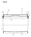
- fig. 2 the container assembly according to fig. 1 after assembly;
- fig. 3 a stack of lid parts before assembly with the container part;
- fig. 4 a perspective top and side view of a lid part according to the invention;
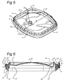
- fig. 5 a perspective bottom and side view of the lid part of fig. 4;
- fig. 6 a cross section of fig. 4,
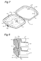
- fig. 7 the lid part of fig. 4 opened, i.e., with the lid hinged open with respect to the connection portion,
- fig. 8 an alternative lid-shape.
- In the figures the container assembly is referred to by 1. It comprises a
lid part 2 and acontainer part 3.Container part 3 is provided with abottom 4 and the bottom material is connected to the side walls and defines acircumferential rim 5. The container part can be made of cardboard, coated with a synthetic coating layer known in the art for making it suitable for containing food or liquids. The container part can also be made of plastic or metal, preferably for holding food or liquids. -
Lid part 2 comprises aconnection portion 8, a (living)hinge 6 and alid 7.Lid 7 is pivotably connected toconnection portion 8.Connection portion 8 comprises a circumferentialU-shaped rim 13 to receive theupper edge 12 of the side wall of thecontainer part 3. Fixation of theconnection portion 8 to the container wall can be effected through any means known in the art. In these drawings, theupper edge 12 of thecontainer part 3 is folded and thus forms a double material layer. In practise, however, this needs not be the case and in most case it is a single layer. - According to the invention the top of
lid 7 is provided with a circumferential cam. In the embodiment shown in the drawings the lid has twocam portions 9 having interruptions 10 (Fig. 4) between them. In the embodiment shown, the cams are parts of thelid 7 bulging out (i.e., away from connection portion 8). It is also conceivable to provide a rim on top of thelid 7. It may even be conceivable to make the cam (circumferentially) bulging in, i.e. towardsconnection portion 8. It than in fact forms a groove. In that case rim 5 at the bottom ofcontainer part 3 is received within this groove. - The top of the
lid 7 is shaped to partially correspond with the shape of a spoon. The shape is indicated by 11 (fig. 4, 5). Inside thelid 7 clamping means (fig 5, nr 29) are provided to accommodate and hold a spoon having the shape and size ofshape 11 of the spoon (not shown). From fig. 4 it is clear that the lid is substantially rectangular andshape 11 is position diagonally.Interruptions 10 of thecam portions 9 are at the position where it "crosses"shape 11. Preferably about 20% of the circumference at the position ofcams 9 comprisesinterruptions 10. - The lid is further provided with a
circumferential rim 14 which in the closed position covers at least the top of theconnection portion 8. Cooperating locking means 31 are provided to lock the lid relative to the connection portion and tamper evident means 30 can be provided over the locking means 31 to prevent abuse. In this embodiment, locking means 31 comprise alip 31 onlid 7 with a cam on its side directed toward thelid 7, and a cam on connectingportion 8. These two cams engage one another thelid 7 is closed and the lockinglip 31 is not operated and disengage when the lockinglip 31 is operated, allowing a user to open thelid 7. In this embodiment, the lockinglip 31 is tiltably connected tolid 7, and is tiltable around an axis in the main plane of thelid 7 and near the boundary of thelid 7. To that end, thelip 31 is connected to thelid 7 via a thinnedpart 26 of the lid (see fig. 6). In case the lockinglip 31 extends above themain surface 22 of thelid 7, as is the case in the embodiment shown here, it proved (part of) gripping means via which a user can grip thelid 7 for opening it. - At the position of the locking lip 31 a gripping
area 28 is provided. In this embodiment, it is created by providing a (local)recess 28 in the lid, and by providingcam 9 in such a way that theinner wall 33 of thiscam 9 runs on into a wall ofrecess 28. In this way, a relativelylarge plane 33 is created onto which a finger or thumb can rest when operating lockinglip 31 with another finger/thumb. - In fig. 6 it is further indicated that
cam 9 has a top 24 which, as already mentioned, extends about 5-7 mm above thesurface 22 defined byrim 14, which substantially defines the plane of thelid 7.Wall 25 is the outer wall ofcam 9. Lockinglip 31 does not extend above this cam in order not to compromise the stackability of lid parts and/or container assemblies. - Tamper evidence means 30 is in this embodiment comprises a
lip 30 which is connected to the connectingportion 8 via thin connecting bridges. These bridges are provided near both sides of lockinglip 31 of the locking means 31 and near the end of the lockinglip 31 of these locking means. The connecting bridges need to be broken in order to remove thesecurity lip 30 and to allow a user to tilt lockinglip 31 of the locking means 31, and can be formed in a (synthetic material, e.g. PE, PP) moulding process of thelid portion 2. In the embodiment shown for instance in fig. 4, it is clear that because a lip is used which is connected using connecting bridges which can be moulded in one go together with the lip and the rest of the lid portion, the security means can be completely integrated in the side wall. In particular, the security lip has apart 35 which extends above the locking lip (at this position, the locking lip has a lower part 36), thus allowing easy removal of thesecurity lip 30. The height of thesecurity lip 30 and of the lockinglip 31 should preferably not extend aboveedge 24 ofcam 9. - According to an aspect of the invention,
cams 9 have a substantial height D, e.g. about 5-7 mm. Furthermore, in this embodiment,cams 9 are part of thelid 7 bulging outward with respect to the main plane of the lid (substantially a plane throughsurface 22 of rim 14). Because of that thecams 9 function as reinforcement ribs adding to the strength of the lid and in this way it is possible to stack a number of container assemblies on top of each other such as is shown for example in fig. 2 in a very stable manner. This effect of providing more rigidity to the lid is increase as a wall of thecam 9 almost extends or goes over intorim 34. Thisrim 34 of the inside of thelid 7 fits in the inside 23 of innerU-shaped rim 20. The innerU-shaped rim 20 hasribs 21 providing rigidity to therim 20. The height of thisinner side 23 ofinner rim 20 is preferably at least the height ofcam 9, i.e. about 5-7 mm.Rim 23 oflid 7 extends within the connectingpart 8 to such an extend that it leaves enough height ofrim 23 free (the already mentioned 5-7 mm) to be able to stably stack lid parts in the way shown in fig. 3. - The spacing between the outsides or
outer walls 25 of thecam portions 9 is indicated in fig. 4 by C. - According to an aspect of the invention the internal width of the
connection portion 8 at least at the lower end thereof is indicated by B, wherein B is slightly larger than C. This allows for stacking of a number of lid parts comprisingconnection portion 8 andlid 7 on top of each other as is shown in fig. 3 to obtain a stable stack. Such a stable stack is desirable during automated provision of the lid parts on the container parts during assembly thereof. - In Fig. 1, the spacing between opposite sides of the
circumferential rim 5 at the bottom side ofcontainer part 3 is indicated by A. Preferably A is about the same as B allowing for stacking of container assemblies using the combination of thecircumferential rim 5 andcam portions 9 of the lid. It will be understood that the dimensions A-C are all taken in the same direction. In different directions A-C will have other values but the same principle applies to provide for stable and robust stacking of both the lid parts and the container assemblies in a later stage. The spacing between the cam and the circumferential rim, the connection portion respectively is preferably about 0,5 mm. Because of the shape of the cam portions there are at least three and preferable four or more points of contact between the related circumferential rim and the cam portions providing a stable stacked assembly. Stacks of ten packages or more can be obtained. The circumferential shape of therim 5 of thecontainer part 3 and of thecam 9 on thelid 7 are mutually adapted in such a way that therim 5 closely fits around thecams 9. Furthermore, the diameter B and circumferential shape ofrim 23 of the connecting portion is designed in such a way that thecircumferential rim 23 of the connecting portion closely fits aroundcam 9 oflid 7. - Although in this preferred embodiment the
cam portions 9 function both to cooperate with corresponding accommodation in theconnection portion 8 and therim 5 atbottom 4 of the container part, it will be obvious that two sets of cam portions can be provided. -
Lid portion 2 further has a levellingpart 27 insiderim 20. Thispart 27 is provided at the edge ofrim 34 at a distance from the lower edge of the inner wall ofrim 20 to allow stacking oflid portions 2. This levellingpart 27 allows levelling of the spoon. -
Lid 7 further has a dome-shapedpart 32 at its centre part for providing additional rigidity oflid 7. - In the embodiment shows in the drawings, the
shape 11 indicating and holding a spoon bulges outward with respect to the plane oflid 7. This may provide additional rigidity tolid 7. It is, however, also conceivable to let for instance the top 24 ofcams 9 define the main plane and outside surface oflid 7. In that case,wall 25 still defines stacking means providing an abutment for therim 5 of the bottom ofcontainer portion 3, together withsurface 22 ofrim 14. In this case, the shape of a spoon may be indicated in another way, and clamping means 29 for a spoon may still be present. - In another shape of
lid 7, shown in fig. 8, connectingpart 8 still has arim 20 withinner side 23 for providing a first element of the first complementary stacking means. In this embodiment of the lid, however, the lid has depressions, in this embodiment a circumferential groove which is dimensioned to retain both rim 20 of thelid part 2 when stacking lid parts, andrim 5 when stackingcontainer assemblies 1. In fact, the groove provides at a groove wall a vertically extending abutment. This vertically extending (with respect to the plane of the lid 7) abutment can also be formed by, when radially following the surface of thelid 7 from the outside 22 to the centre, lowering the surface of the lid with respect to surface 22 ofrim 14, thus providing an abutment against forces radially outward. The vertically extending abutment can also be formed by making the surface of the lid higher aftersurface 22 ofrim 14, thus providing an abutment against forces radially inward. In the first embodiment, the outside ofrim 5 abuts the abutment of thelid 7, in the second embodiment, the inside ofrim 5 abuts the abutment of thelid 7. In both embodiments, the abutment of the lid prevents shifting. It is clear that these abutments do not need to be completely circumferential, but in many designs and practical embodiments, they will be. - It will also be obvious after the above that further embodiments are within the scope of protection of the appended claims being obvious combinations with prior art techniques and the disclosure of this patent.
Claims (16)
- Container assembly (1) comprising a container part (3) and a lid part (2), said lid part (2) comprising a connection portion (8) for connection to said container part (3) and a lid (7) being pivotably connected to said connection portion (8), characterised in that the side remote from said lid (7) of said connection portion (8) and the side of the lid (7) remote from the connection portion (8) are provided with first complementary stacking means (9, 14, 22, 25, 20, 23, 34).
- Container assembly according to claim 1, wherein said complementary stacking means comprise a cam (9) and recess or rim (20, 22).
- Container assembly to one of the preceding claims, wherein said cam (9) is provided on the lid (7) on the side remote from said connection portion (8).
- Container assembly to one of the preceding claims, wherein the bottom (4) of said container part (3) and the side of said lid (7) being remote from said connection portion are provided with second complementary stacking means (5, 9, 14, 22, 25).
- Container assembly according to claim 4, wherein said first and second stacking means on said lid are identical.
- Container assembly according to one of the preceding claims in combination of claim 3, wherein said cam comprises a circumferential cam extending near the outer circumference of said lid.
- Container assembly according to claim 6, wherein said circumferential cam is provided with interruptions (10).
- Container assembly according to claim 7, wherein said lid (7) is smooth at a location of said interruptions (10).
- Container assembly according to one of the preceding claims, wherein said lid (7) is arranged for internally accommodating a spoon, wherein in said lid the at least partial shape (11) of said spoon is provided.
- Container assembly according to claims 8 and 9, wherein said interruption (10) is provided at the location of said at least partial shape (11).
- Container assembly according to one of the claims 9 or 10, wherein said lid (7) is rectangular and said at least partial shape (11) extends diagonally.
- Container assembly according to claim 11, wherein the angles of said rectangle are curved and one side is convex shaped.
- Container assembly according to any one of the preceding claims, wherein said lid (7) comprising a lip (31) for locking said lid (7) to said connection portion (8), said locking lip (31) being operably connected to said lid (7) and having a cam and said connecting portion having a further cam, both cams positioned for engaging one another to keep said lid locked onto said connecting portion when said locking lip is not operated and to disengage one another when said locking lip is operated, said lid further having a gripping area (28) adjacent said locking lip for arrangement of a finger or thumb of a user when operating said lip.
- Container assembly according to any one of the preceding claims, wherein the lid (7) is provided with at least one abutment (34) extending in normal direction with respect to a plane of the lid for providing abutment against forces with a component parallel to the plane of the lid, as a part of said first complementary stacking means.
- Container assembly according to any one of the preceding claims, wherein the side of said connection portion (8) remote from said lid (7) is provided with a circumferential rim (20) as a part of said first complementary stacking means
- Container assembly according to any one of the preceding claims, wherein said lid (7) comprising a lip (31) for locking said lid (7) to said connection portion (8), said locking lip (31) being operably connected to said lid and having a cam and said connecting portion having a further cam, both cams positioned for engaging one another to keep said lid onto said connecting portion when said locking lip is not operated and to disengage one another when said locking lip is operated, and said connection portion further comprises a security lip (30) positioned over said locking lip (31) for preventing operation of said locking lip and providing temper evidence.
Priority Applications (2)
| Application Number | Priority Date | Filing Date | Title |
|---|---|---|---|
| EP07109447.8A EP1864914B2 (en) | 2006-06-09 | 2007-06-01 | Container assembly having stacking means |
| PL07109447T PL1864914T5 (en) | 2006-06-09 | 2007-06-01 | Container assembly having stacking means |
Applications Claiming Priority (2)
| Application Number | Priority Date | Filing Date | Title |
|---|---|---|---|
| EP06115219 | 2006-06-09 | ||
| EP07109447.8A EP1864914B2 (en) | 2006-06-09 | 2007-06-01 | Container assembly having stacking means |
Publications (3)
| Publication Number | Publication Date |
|---|---|
| EP1864914A1 true EP1864914A1 (en) | 2007-12-12 |
| EP1864914B1 EP1864914B1 (en) | 2010-04-14 |
| EP1864914B2 EP1864914B2 (en) | 2017-10-04 |
Family
ID=40947282
Family Applications (1)
| Application Number | Title | Priority Date | Filing Date |
|---|---|---|---|
| EP07109447.8A Active EP1864914B2 (en) | 2006-06-09 | 2007-06-01 | Container assembly having stacking means |
Country Status (8)
| Country | Link |
|---|---|
| EP (1) | EP1864914B2 (en) |
| CN (1) | CN101500898B (en) |
| AT (1) | ATE464235T2 (en) |
| DE (1) | DE602007005868D1 (en) |
| DK (1) | DK1864914T4 (en) |
| ES (1) | ES2344477T5 (en) |
| PL (1) | PL1864914T5 (en) |
| PT (1) | PT1864914E (en) |
Cited By (4)
| Publication number | Priority date | Publication date | Assignee | Title |
|---|---|---|---|---|
| NL1035660C2 (en) * | 2008-07-01 | 2010-01-05 | James Bunese Bosheya | Plastic lid for tea cup in e.g. public places, has separate head provided in middle part, spoon and tea bag arranged in cylinder, and two plastic cubes fixed on middle part, where spoon is fixed between two plastic cubes |
| CN102282079A (en) * | 2008-12-15 | 2011-12-14 | 荷兰纽迪希亚公司 | Cover parts for containers |
| WO2016072911A1 (en) * | 2014-11-03 | 2016-05-12 | Å&R Carton Lund Aktiebolag | Container with display function |
| WO2017204731A1 (en) * | 2016-05-23 | 2017-11-30 | Å&R Carton Lund Aktiebolag | Packaging container with stacking members |
Families Citing this family (7)
| Publication number | Priority date | Publication date | Assignee | Title |
|---|---|---|---|---|
| EP2421764B2 (en) † | 2009-04-24 | 2022-01-05 | N.V. Nutricia | Container assembly having stacking provisions |
| CN102514809A (en) * | 2011-12-19 | 2012-06-27 | 内蒙古伊利实业集团股份有限公司 | Plastic sealing cover for milk powder can |
| MX384736B (en) * | 2014-10-15 | 2025-03-14 | Mjn Us Holdings Llc | HINGED PLASTIC LID. |
| CN104354977A (en) * | 2014-10-29 | 2015-02-18 | 无锡同心塑料制品有限公司 | Portable honey loading pot |
| CN107572127A (en) * | 2017-09-27 | 2018-01-12 | 孙德善 | Container connection component |
| ES3060986T3 (en) | 2021-05-27 | 2026-03-30 | Bluewater Innovations Ab | Container |
| CN117396408A (en) * | 2021-05-27 | 2024-01-12 | 蓝水创新公司 | container |
Citations (5)
| Publication number | Priority date | Publication date | Assignee | Title |
|---|---|---|---|---|
| EP0072294A1 (en) * | 1981-08-11 | 1983-02-16 | LE MOULAGE AUTOMATIQUE Société Anonyme | Inviolable telescopable cover for a container with a many-sided section |
| US5219087A (en) * | 1989-05-31 | 1993-06-15 | Akerlund & Rausing Licens Ab | Tamperproof reclosing lid |
| EP1512637A1 (en) * | 2003-08-29 | 2005-03-09 | Huhtamaki France S.A. | Closure lid for food containers |
| WO2005075314A2 (en) * | 2004-02-05 | 2005-08-18 | N.V. Nutricia | Packaging for pulverulent material |
| US20060068063A1 (en) * | 2004-09-24 | 2006-03-30 | Zerfas Paul A | Multiple compartment package |
Family Cites Families (12)
| Publication number | Priority date | Publication date | Assignee | Title |
|---|---|---|---|---|
| US4364476A (en) † | 1982-01-05 | 1982-12-21 | Shamrock Industries, Inc. | Plastic lid with stacking separation means |
| US4759478A (en) † | 1982-05-03 | 1988-07-26 | International Paper Company | Hinged plug type lid |
| US5083671A (en) * | 1989-12-13 | 1992-01-28 | Anchor Hocking Packaging Company | Closure for a wide mouth container |
| SE507647C2 (en) † | 1992-03-05 | 1998-06-29 | Akerlund & Rausing Licens Ab | Large or heavy packs with recoil stop |
| CA2103830C (en) † | 1992-08-19 | 2005-05-17 | Gerald M. Syrek | Stackable container for premoistened wipes |
| WO2002047997A1 (en) † | 2000-12-13 | 2002-06-20 | Controlled Molding, Inc. | Stackable non-round plastic closure with resealable flap |
| US6712233B2 (en) † | 2001-03-13 | 2004-03-30 | Stephen H. Arshinoff | Lid with hinge for plastic pail |
| US6478183B1 (en) † | 2001-04-27 | 2002-11-12 | Sonoco Development, Inc. | Lightweight overcap having intermittent nesting and stacking elements |
| GB0130619D0 (en) † | 2001-12-20 | 2002-02-06 | Insulpak Ltd | A Lid |
| JP4238649B2 (en) † | 2003-06-19 | 2009-03-18 | 凸版印刷株式会社 | Cap with small lid for opening and closing the mouth |
| US7784635B2 (en) † | 2004-10-07 | 2010-08-31 | Ropak Corporation | Container and lid with multiple chambers |
| US7726483B2 (en) † | 2005-02-23 | 2010-06-01 | The Glad Products Company | Stacked containers |
-
2007
- 2007-06-01 EP EP07109447.8A patent/EP1864914B2/en active Active
- 2007-06-01 CN CN2007800294323A patent/CN101500898B/en active Active
- 2007-06-01 PL PL07109447T patent/PL1864914T5/en unknown
- 2007-06-01 AT AT07109447T patent/ATE464235T2/en active
- 2007-06-01 PT PT07109447T patent/PT1864914E/en unknown
- 2007-06-01 DE DE602007005868T patent/DE602007005868D1/en active Active
- 2007-06-01 ES ES07109447.8T patent/ES2344477T5/en active Active
- 2007-06-01 DK DK07109447.8T patent/DK1864914T4/en active
Patent Citations (5)
| Publication number | Priority date | Publication date | Assignee | Title |
|---|---|---|---|---|
| EP0072294A1 (en) * | 1981-08-11 | 1983-02-16 | LE MOULAGE AUTOMATIQUE Société Anonyme | Inviolable telescopable cover for a container with a many-sided section |
| US5219087A (en) * | 1989-05-31 | 1993-06-15 | Akerlund & Rausing Licens Ab | Tamperproof reclosing lid |
| EP1512637A1 (en) * | 2003-08-29 | 2005-03-09 | Huhtamaki France S.A. | Closure lid for food containers |
| WO2005075314A2 (en) * | 2004-02-05 | 2005-08-18 | N.V. Nutricia | Packaging for pulverulent material |
| US20060068063A1 (en) * | 2004-09-24 | 2006-03-30 | Zerfas Paul A | Multiple compartment package |
Cited By (11)
| Publication number | Priority date | Publication date | Assignee | Title |
|---|---|---|---|---|
| NL1035660C2 (en) * | 2008-07-01 | 2010-01-05 | James Bunese Bosheya | Plastic lid for tea cup in e.g. public places, has separate head provided in middle part, spoon and tea bag arranged in cylinder, and two plastic cubes fixed on middle part, where spoon is fixed between two plastic cubes |
| CN102282079A (en) * | 2008-12-15 | 2011-12-14 | 荷兰纽迪希亚公司 | Cover parts for containers |
| CN102282079B (en) * | 2008-12-15 | 2015-04-22 | 荷兰纽迪希亚公司 | Cover parts for containers |
| CN104724376A (en) * | 2008-12-15 | 2015-06-24 | 荷兰纽迪希亚公司 | Lid part for a container |
| CN104724376B (en) * | 2008-12-15 | 2021-06-01 | 荷兰纽迪希亚公司 | Lid parts for containers |
| WO2016072911A1 (en) * | 2014-11-03 | 2016-05-12 | Å&R Carton Lund Aktiebolag | Container with display function |
| CN107000904A (en) * | 2014-11-03 | 2017-08-01 | A和R卡顿隆德有限公司 | Container with display function |
| EP3215435A4 (en) * | 2014-11-03 | 2018-06-20 | Å&R Carton Lund AB | Container with display function |
| US10370158B2 (en) | 2014-11-03 | 2019-08-06 | Å&R Carton Lund Aktiebolag | Container with display function |
| WO2017204731A1 (en) * | 2016-05-23 | 2017-11-30 | Å&R Carton Lund Aktiebolag | Packaging container with stacking members |
| US11192688B2 (en) | 2016-05-23 | 2021-12-07 | Ar Packaging Systems Ab | Packaging container with stacking members |
Also Published As
| Publication number | Publication date |
|---|---|
| ES2344477T5 (en) | 2018-02-05 |
| DK1864914T3 (en) | 2010-07-19 |
| PL1864914T5 (en) | 2018-05-30 |
| EP1864914B1 (en) | 2010-04-14 |
| DK1864914T4 (en) | 2018-01-02 |
| PT1864914E (en) | 2010-07-21 |
| ES2344477T3 (en) | 2010-08-27 |
| CN101500898B (en) | 2011-10-05 |
| ATE464235T2 (en) | 2010-04-15 |
| CN101500898A (en) | 2009-08-05 |
| DE602007005868D1 (en) | 2010-05-27 |
| EP1864914B2 (en) | 2017-10-04 |
| PL1864914T3 (en) | 2010-09-30 |
Similar Documents
| Publication | Publication Date | Title |
|---|---|---|
| EP2325094B1 (en) | Container assembly having stacking means | |
| EP1864914B1 (en) | Container assembly having stacking means | |
| US20070284276A1 (en) | Container assembly having stacking means | |
| US10005596B2 (en) | Container | |
| US8646648B2 (en) | Container system | |
| US7784635B2 (en) | Container and lid with multiple chambers | |
| DK2956377T3 (en) | CONTAINER WITH A BASE AND LOW | |
| CA1284631C (en) | Molded lid assembly with primary and secondary latching features | |
| US4014459A (en) | Container closure | |
| US20170334612A1 (en) | Container | |
| US8056758B2 (en) | Non-cylindrical container and lid | |
| EP1681242A1 (en) | A container | |
| EP2560891B1 (en) | Stackable package container with ribbed lid for easy sliding off from a stack | |
| HK1212309B (en) | Lid attached to a container by a collar |
Legal Events
| Date | Code | Title | Description |
|---|---|---|---|
| PUAI | Public reference made under article 153(3) epc to a published international application that has entered the european phase |
Free format text: ORIGINAL CODE: 0009012 |
|
| AK | Designated contracting states |
Kind code of ref document: A1 Designated state(s): AT BE BG CH CY CZ DE DK EE ES FI FR GB GR HU IE IS IT LI LT LU LV MC MT NL PL PT RO SE SI SK TR |
|
| AX | Request for extension of the european patent |
Extension state: AL BA HR MK YU |
|
| 17P | Request for examination filed |
Effective date: 20080611 |
|
| AKX | Designation fees paid |
Designated state(s): AT BE BG CH CY CZ DE DK EE ES FI FR GB GR HU IE IS IT LI LT LU LV MC MT NL PL PT RO SE SI SK TR |
|
| 17Q | First examination report despatched |
Effective date: 20081010 |
|
| GRAP | Despatch of communication of intention to grant a patent |
Free format text: ORIGINAL CODE: EPIDOSNIGR1 |
|
| GRAS | Grant fee paid |
Free format text: ORIGINAL CODE: EPIDOSNIGR3 |
|
| GRAA | (expected) grant |
Free format text: ORIGINAL CODE: 0009210 |
|
| AK | Designated contracting states |
Kind code of ref document: B1 Designated state(s): AT BE BG CH CY CZ DE DK EE ES FI FR GB GR HU IE IS IT LI LT LU LV MC MT NL PL PT RO SE SI SK TR |
|
| REG | Reference to a national code |
Ref country code: GB Ref legal event code: FG4D |
|
| REG | Reference to a national code |
Ref country code: CH Ref legal event code: EP |
|
| REG | Reference to a national code |
Ref country code: IE Ref legal event code: FG4D |
|
| REF | Corresponds to: |
Ref document number: 602007005868 Country of ref document: DE Date of ref document: 20100527 Kind code of ref document: P |
|
| REG | Reference to a national code |
Ref country code: DK Ref legal event code: T3 |
|
| REG | Reference to a national code |
Ref country code: NL Ref legal event code: T3 Ref country code: PT Ref legal event code: SC4A Free format text: AVAILABILITY OF NATIONAL TRANSLATION Effective date: 20100713 |
|
| REG | Reference to a national code |
Ref country code: ES Ref legal event code: FG2A Ref document number: 2344477 Country of ref document: ES Kind code of ref document: T3 |
|
| LTIE | Lt: invalidation of european patent or patent extension |
Effective date: 20100414 |
|
| REG | Reference to a national code |
Ref country code: PL Ref legal event code: T3 |
|
| PG25 | Lapsed in a contracting state [announced via postgrant information from national office to epo] |
Ref country code: SE Free format text: LAPSE BECAUSE OF FAILURE TO SUBMIT A TRANSLATION OF THE DESCRIPTION OR TO PAY THE FEE WITHIN THE PRESCRIBED TIME-LIMIT Effective date: 20100414 Ref country code: LT Free format text: LAPSE BECAUSE OF FAILURE TO SUBMIT A TRANSLATION OF THE DESCRIPTION OR TO PAY THE FEE WITHIN THE PRESCRIBED TIME-LIMIT Effective date: 20100414 |
|
| PG25 | Lapsed in a contracting state [announced via postgrant information from national office to epo] |
Ref country code: LV Free format text: LAPSE BECAUSE OF FAILURE TO SUBMIT A TRANSLATION OF THE DESCRIPTION OR TO PAY THE FEE WITHIN THE PRESCRIBED TIME-LIMIT Effective date: 20100414 Ref country code: FI Free format text: LAPSE BECAUSE OF FAILURE TO SUBMIT A TRANSLATION OF THE DESCRIPTION OR TO PAY THE FEE WITHIN THE PRESCRIBED TIME-LIMIT Effective date: 20100414 Ref country code: SI Free format text: LAPSE BECAUSE OF FAILURE TO SUBMIT A TRANSLATION OF THE DESCRIPTION OR TO PAY THE FEE WITHIN THE PRESCRIBED TIME-LIMIT Effective date: 20100414 Ref country code: IS Free format text: LAPSE BECAUSE OF FAILURE TO SUBMIT A TRANSLATION OF THE DESCRIPTION OR TO PAY THE FEE WITHIN THE PRESCRIBED TIME-LIMIT Effective date: 20100814 |
|
| PG25 | Lapsed in a contracting state [announced via postgrant information from national office to epo] |
Ref country code: CY Free format text: LAPSE BECAUSE OF FAILURE TO SUBMIT A TRANSLATION OF THE DESCRIPTION OR TO PAY THE FEE WITHIN THE PRESCRIBED TIME-LIMIT Effective date: 20100519 |
|
| PLBI | Opposition filed |
Free format text: ORIGINAL CODE: 0009260 |
|
| PG25 | Lapsed in a contracting state [announced via postgrant information from national office to epo] |
Ref country code: EE Free format text: LAPSE BECAUSE OF FAILURE TO SUBMIT A TRANSLATION OF THE DESCRIPTION OR TO PAY THE FEE WITHIN THE PRESCRIBED TIME-LIMIT Effective date: 20100414 Ref country code: MC Free format text: LAPSE BECAUSE OF NON-PAYMENT OF DUE FEES Effective date: 20100630 |
|
| 26 | Opposition filed |
Opponent name: A&R CARTON LUND AB Effective date: 20110112 |
|
| PG25 | Lapsed in a contracting state [announced via postgrant information from national office to epo] |
Ref country code: CZ Free format text: LAPSE BECAUSE OF FAILURE TO SUBMIT A TRANSLATION OF THE DESCRIPTION OR TO PAY THE FEE WITHIN THE PRESCRIBED TIME-LIMIT Effective date: 20100414 Ref country code: SK Free format text: LAPSE BECAUSE OF FAILURE TO SUBMIT A TRANSLATION OF THE DESCRIPTION OR TO PAY THE FEE WITHIN THE PRESCRIBED TIME-LIMIT Effective date: 20100414 Ref country code: RO Free format text: LAPSE BECAUSE OF FAILURE TO SUBMIT A TRANSLATION OF THE DESCRIPTION OR TO PAY THE FEE WITHIN THE PRESCRIBED TIME-LIMIT Effective date: 20100414 |
|
| PLAX | Notice of opposition and request to file observation + time limit sent |
Free format text: ORIGINAL CODE: EPIDOSNOBS2 |
|
| PG25 | Lapsed in a contracting state [announced via postgrant information from national office to epo] |
Ref country code: IT Free format text: LAPSE BECAUSE OF NON-PAYMENT OF DUE FEES Effective date: 20100601 |
|
| PG25 | Lapsed in a contracting state [announced via postgrant information from national office to epo] |
Ref country code: MT Free format text: LAPSE BECAUSE OF FAILURE TO SUBMIT A TRANSLATION OF THE DESCRIPTION OR TO PAY THE FEE WITHIN THE PRESCRIBED TIME-LIMIT Effective date: 20100414 Ref country code: GR Free format text: LAPSE BECAUSE OF FAILURE TO SUBMIT A TRANSLATION OF THE DESCRIPTION OR TO PAY THE FEE WITHIN THE PRESCRIBED TIME-LIMIT Effective date: 20100715 |
|
| PLAF | Information modified related to communication of a notice of opposition and request to file observations + time limit |
Free format text: ORIGINAL CODE: EPIDOSCOBS2 |
|
| PLBB | Reply of patent proprietor to notice(s) of opposition received |
Free format text: ORIGINAL CODE: EPIDOSNOBS3 |
|
| APBM | Appeal reference recorded |
Free format text: ORIGINAL CODE: EPIDOSNREFNO |
|
| APBP | Date of receipt of notice of appeal recorded |
Free format text: ORIGINAL CODE: EPIDOSNNOA2O |
|
| APAH | Appeal reference modified |
Free format text: ORIGINAL CODE: EPIDOSCREFNO |
|
| APBM | Appeal reference recorded |
Free format text: ORIGINAL CODE: EPIDOSNREFNO |
|
| APBP | Date of receipt of notice of appeal recorded |
Free format text: ORIGINAL CODE: EPIDOSNNOA2O |
|
| PG25 | Lapsed in a contracting state [announced via postgrant information from national office to epo] |
Ref country code: LU Free format text: LAPSE BECAUSE OF NON-PAYMENT OF DUE FEES Effective date: 20100601 Ref country code: BG Free format text: LAPSE BECAUSE OF FAILURE TO SUBMIT A TRANSLATION OF THE DESCRIPTION OR TO PAY THE FEE WITHIN THE PRESCRIBED TIME-LIMIT Effective date: 20100414 Ref country code: HU Free format text: LAPSE BECAUSE OF FAILURE TO SUBMIT A TRANSLATION OF THE DESCRIPTION OR TO PAY THE FEE WITHIN THE PRESCRIBED TIME-LIMIT Effective date: 20101015 |
|
| APBQ | Date of receipt of statement of grounds of appeal recorded |
Free format text: ORIGINAL CODE: EPIDOSNNOA3O |
|
| PG25 | Lapsed in a contracting state [announced via postgrant information from national office to epo] |
Ref country code: BG Free format text: LAPSE BECAUSE OF FAILURE TO SUBMIT A TRANSLATION OF THE DESCRIPTION OR TO PAY THE FEE WITHIN THE PRESCRIBED TIME-LIMIT Effective date: 20100714 |
|
| PLAB | Opposition data, opponent's data or that of the opponent's representative modified |
Free format text: ORIGINAL CODE: 0009299OPPO |
|
| R26 | Opposition filed (corrected) |
Opponent name: A&R CARTON LUND AB Effective date: 20110112 |
|
| REG | Reference to a national code |
Ref country code: FR Ref legal event code: PLFP Year of fee payment: 10 |
|
| APBU | Appeal procedure closed |
Free format text: ORIGINAL CODE: EPIDOSNNOA9O |
|
| APAN | Information on closure of appeal procedure modified |
Free format text: ORIGINAL CODE: EPIDOSCNOA9O |
|
| REG | Reference to a national code |
Ref country code: FR Ref legal event code: PLFP Year of fee payment: 11 |
|
| PUAH | Patent maintained in amended form |
Free format text: ORIGINAL CODE: 0009272 |
|
| STAA | Information on the status of an ep patent application or granted ep patent |
Free format text: STATUS: PATENT MAINTAINED AS AMENDED |
|
| 27A | Patent maintained in amended form |
Effective date: 20171004 |
|
| AK | Designated contracting states |
Kind code of ref document: B2 Designated state(s): AT BE BG CH CY CZ DE DK EE ES FI FR GB GR HU IE IS IT LI LT LU LV MC MT NL PL PT RO SE SI SK TR |
|
| REG | Reference to a national code |
Ref country code: DE Ref legal event code: R102 Ref document number: 602007005868 Country of ref document: DE |
|
| REG | Reference to a national code |
Ref country code: CH Ref legal event code: AELC |
|
| REG | Reference to a national code |
Ref country code: DK Ref legal event code: T4 Effective date: 20171219 |
|
| REG | Reference to a national code |
Ref country code: ES Ref legal event code: DC2A Ref document number: 2344477 Country of ref document: ES Kind code of ref document: T5 Effective date: 20180205 |
|
| REG | Reference to a national code |
Ref country code: NL Ref legal event code: MP Effective date: 20100414 |
|
| PG25 | Lapsed in a contracting state [announced via postgrant information from national office to epo] |
Ref country code: NL Free format text: LAPSE BECAUSE OF FAILURE TO SUBMIT A TRANSLATION OF THE DESCRIPTION OR TO PAY THE FEE WITHIN THE PRESCRIBED TIME-LIMIT Effective date: 20100414 |
|
| PG25 | Lapsed in a contracting state [announced via postgrant information from national office to epo] |
Ref country code: LV Free format text: LAPSE BECAUSE OF FAILURE TO SUBMIT A TRANSLATION OF THE DESCRIPTION OR TO PAY THE FEE WITHIN THE PRESCRIBED TIME-LIMIT Effective date: 20171004 |
|
| REG | Reference to a national code |
Ref country code: FR Ref legal event code: PLFP Year of fee payment: 12 |
|
| REG | Reference to a national code |
Ref country code: NL Ref legal event code: NE Effective date: 20180810 |
|
| REG | Reference to a national code |
Ref country code: NL Ref legal event code: FP Ref country code: NL Ref legal event code: NG |
|
| PG25 | Lapsed in a contracting state [announced via postgrant information from national office to epo] |
Ref country code: NL Free format text: LAPSE BECAUSE OF FAILURE TO SUBMIT A TRANSLATION OF THE DESCRIPTION OR TO PAY THE FEE WITHIN THE PRESCRIBED TIME-LIMIT Effective date: 20100414 |
|
| PGRI | Patent reinstated in contracting state [announced from national office to epo] |
Ref country code: NL Effective date: 20190417 |
|
| PGFP | Annual fee paid to national office [announced via postgrant information from national office to epo] |
Ref country code: TR Payment date: 20190521 Year of fee payment: 13 |
|
| PGFP | Annual fee paid to national office [announced via postgrant information from national office to epo] |
Ref country code: AT Payment date: 20190626 Year of fee payment: 13 |
|
| REG | Reference to a national code |
Ref country code: DK Ref legal event code: EBP Effective date: 20200630 |
|
| PG25 | Lapsed in a contracting state [announced via postgrant information from national office to epo] |
Ref country code: PT Free format text: LAPSE BECAUSE OF NON-PAYMENT OF DUE FEES Effective date: 20201202 |
|
| REG | Reference to a national code |
Ref country code: AT Ref legal event code: MM01 Ref document number: 464235 Country of ref document: AT Kind code of ref document: T Effective date: 20200601 |
|
| PG25 | Lapsed in a contracting state [announced via postgrant information from national office to epo] |
Ref country code: PT Free format text: LAPSE BECAUSE OF NON-PAYMENT OF DUE FEES Effective date: 20210104 |
|
| REG | Reference to a national code |
Ref country code: AT Ref legal event code: UEP Ref document number: 464235 Country of ref document: AT Kind code of ref document: T Effective date: 20171004 |
|
| PG25 | Lapsed in a contracting state [announced via postgrant information from national office to epo] |
Ref country code: AT Free format text: LAPSE BECAUSE OF NON-PAYMENT OF DUE FEES Effective date: 20200601 |
|
| PG25 | Lapsed in a contracting state [announced via postgrant information from national office to epo] |
Ref country code: DK Free format text: LAPSE BECAUSE OF NON-PAYMENT OF DUE FEES Effective date: 20200630 |
|
| PG25 | Lapsed in a contracting state [announced via postgrant information from national office to epo] |
Ref country code: TR Free format text: LAPSE BECAUSE OF NON-PAYMENT OF DUE FEES Effective date: 20200601 |
|
| P01 | Opt-out of the competence of the unified patent court (upc) registered |
Effective date: 20230513 |
|
| PGFP | Annual fee paid to national office [announced via postgrant information from national office to epo] |
Ref country code: ES Payment date: 20250710 Year of fee payment: 19 |
|
| PGFP | Annual fee paid to national office [announced via postgrant information from national office to epo] |
Ref country code: CH Payment date: 20250701 Year of fee payment: 19 |
|
| REG | Reference to a national code |
Ref country code: CH Ref legal event code: U11 Free format text: ST27 STATUS EVENT CODE: U-0-0-U10-U11 (AS PROVIDED BY THE NATIONAL OFFICE) Effective date: 20260701 |
|
| PGFP | Annual fee paid to national office [announced via postgrant information from national office to epo] |
Ref country code: GB Payment date: 20260513 Year of fee payment: 20 Ref country code: PL Payment date: 20260511 Year of fee payment: 20 |
|
| PGFP | Annual fee paid to national office [announced via postgrant information from national office to epo] |
Ref country code: IT Payment date: 20260623 Year of fee payment: 20 |
|
| PGFP | Annual fee paid to national office [announced via postgrant information from national office to epo] |
Ref country code: DE Payment date: 20260623 Year of fee payment: 20 |
|
| PGFP | Annual fee paid to national office [announced via postgrant information from national office to epo] |
Ref country code: IE Payment date: 20260617 Year of fee payment: 20 Ref country code: BE Payment date: 20260622 Year of fee payment: 20 |
|
| PGFP | Annual fee paid to national office [announced via postgrant information from national office to epo] |
Ref country code: NL Payment date: 20260602 Year of fee payment: 20 |
|
| PGFP | Annual fee paid to national office [announced via postgrant information from national office to epo] |
Ref country code: FR Payment date: 20260622 Year of fee payment: 20 |