EP1864120B1 - Docking station for a sensor cartridge - Google Patents
Docking station for a sensor cartridge Download PDFInfo
- Publication number
- EP1864120B1 EP1864120B1 EP06726570A EP06726570A EP1864120B1 EP 1864120 B1 EP1864120 B1 EP 1864120B1 EP 06726570 A EP06726570 A EP 06726570A EP 06726570 A EP06726570 A EP 06726570A EP 1864120 B1 EP1864120 B1 EP 1864120B1
- Authority
- EP
- European Patent Office
- Prior art keywords
- docking station
- cartridge
- sensor
- electrical connector
- station according
- Prior art date
- Legal status (The legal status is an assumption and is not a legal conclusion. Google has not performed a legal analysis and makes no representation as to the accuracy of the status listed.)
- Expired - Lifetime
Links
Images







Classifications
-
- G—PHYSICS
- G01—MEASURING; TESTING
- G01N—INVESTIGATING OR ANALYSING MATERIALS BY DETERMINING THEIR CHEMICAL OR PHYSICAL PROPERTIES
- G01N29/00—Investigating or analysing materials by the use of ultrasonic, sonic or infrasonic waves; Visualisation of the interior of objects by transmitting ultrasonic or sonic waves through the object
- G01N29/02—Analysing fluids
- G01N29/036—Analysing fluids by measuring frequency or resonance of acoustic waves
-
- B—PERFORMING OPERATIONS; TRANSPORTING
- B01—PHYSICAL OR CHEMICAL PROCESSES OR APPARATUS IN GENERAL
- B01L—CHEMICAL OR PHYSICAL LABORATORY APPARATUS FOR GENERAL USE
- B01L9/00—Supporting devices; Holding devices
- B01L9/52—Supports specially adapted for flat sample carriers, e.g. for plates, slides, chips
- B01L9/527—Supports specially adapted for flat sample carriers, e.g. for plates, slides, chips for microfluidic devices, e.g. used for lab-on-a-chip
-
- B—PERFORMING OPERATIONS; TRANSPORTING
- B01—PHYSICAL OR CHEMICAL PROCESSES OR APPARATUS IN GENERAL
- B01L—CHEMICAL OR PHYSICAL LABORATORY APPARATUS FOR GENERAL USE
- B01L2200/00—Solutions for specific problems relating to chemical or physical laboratory apparatus
- B01L2200/02—Adapting objects or devices to another
- B01L2200/026—Fluid interfacing between devices or objects, e.g. connectors, inlet details
- B01L2200/027—Fluid interfacing between devices or objects, e.g. connectors, inlet details for microfluidic devices
-
- B—PERFORMING OPERATIONS; TRANSPORTING
- B01—PHYSICAL OR CHEMICAL PROCESSES OR APPARATUS IN GENERAL
- B01L—CHEMICAL OR PHYSICAL LABORATORY APPARATUS FOR GENERAL USE
- B01L2300/00—Additional constructional details
- B01L2300/08—Geometry, shape and general structure
- B01L2300/0809—Geometry, shape and general structure rectangular shaped
- B01L2300/0825—Test strips
-
- B—PERFORMING OPERATIONS; TRANSPORTING
- B01—PHYSICAL OR CHEMICAL PROCESSES OR APPARATUS IN GENERAL
- B01L—CHEMICAL OR PHYSICAL LABORATORY APPARATUS FOR GENERAL USE
- B01L3/00—Containers or dishes for laboratory use, e.g. laboratory glassware; Droppers
- B01L3/50—Containers for the purpose of retaining a material to be analysed, e.g. test tubes
- B01L3/502—Containers for the purpose of retaining a material to be analysed, e.g. test tubes with fluid transport, e.g. in multi-compartment structures
- B01L3/5027—Containers for the purpose of retaining a material to be analysed, e.g. test tubes with fluid transport, e.g. in multi-compartment structures by integrated microfluidic structures, i.e. dimensions of channels and chambers are such that surface tension forces are important, e.g. lab-on-a-chip
-
- G—PHYSICS
- G01—MEASURING; TESTING
- G01N—INVESTIGATING OR ANALYSING MATERIALS BY DETERMINING THEIR CHEMICAL OR PHYSICAL PROPERTIES
- G01N2291/00—Indexing codes associated with group G01N29/00
- G01N2291/02—Indexing codes associated with the analysed material
- G01N2291/025—Change of phase or condition
- G01N2291/0256—Adsorption, desorption, surface mass change, e.g. on biosensors
Definitions
- This invention relates to a docking station for releasably receiving a cartridge for use in analysing a sample comprising fluid, and to analysing apparatus which includes such a docking station and cartridge.
- the invention is particularly, but not exclusively, applicable o a quartz crystal microbalance system, which uses an electrical-mechanical transducer as a sensor. In such a system, an electrical signal causes the transducer to vibrate.
- the crystal typically has an active surface on which a receptor group is immobilised. That group has a chemical affinity or reactivity towards a substance to be detected or analysed.
- the substance to be analysed is normally present in a fluid which is bought into contact with the active surface of the crystal. Physical, chemical and biochemical interactions between the receptor group on the active surface and the substance cause a change in the mass attached to the surface (and in other physical properties of the active surface) and these affect the vibrational characteristics, in particular the resonant frequency, of the crystal. Analysis of these effects can be used to obtain qualitative and/or quantitative data on the substance, and its interaction with the receptor.
- This type of analysing apparatus is used in situations, for example to analyse chemical and biochemical interactions, in which it may be desirable to interchange the sensor with another sensor which may be identical to the first sensor or may carry a different receptor group.
- the docking station also connects the electrodes on the sensor to driving/measuring circuitry for oscillating the sensor and measuring the frequency of oscillation and/or other characteristics of the oscillation (for example the magnitude of the damping force being experienced by the sensor).
- the cartridge comprises an injection moulded body which has an annular rib that surrounds a surface that is to form the base of the flow cell and that includes inlet and outlet openings which communicate with an inlet and outlet of the cartridge through small tubes.
- the sensor is adhered to the rib which spaces the sensor from the other surface so that the sensor, the surface and the rib between them define the flow cell.
- the cartridge is received in a docking station that comprises a lid pivotally mounted on a base.
- the base includes fluid conduits for connecting the inlet and outlet ribs of the cartridge to a sample delivery/removal system, whilst the lid of the mechanism includes an electrical connector for connecting the electrodes of the sensor to the drive/measurement circuitry.
- the connector is described as being spring loaded, it appears to exert enough force on the cartridge to require that the connector engages contacts which are laterally spaced from the sensor so that the electrical connector does not exert a force directly on the sensor.
- the cartridge is of a relatively complicated construction having two spaced apart contacts for the electrical connector and wires connecting those contacts to the electrodes on the sensor.
- a docking station for a piezoelectric sensor is described in WO 2004/057319 .
- a docking station for releasably receiving a cartridge for use in analysing a sample comprising a fluid, the cartridge having a flow cell for the sample and an electrically operated sensor for performing said analysis, the docking station comprising a clamping mechanism for urging fluid connector means against the cartridge to provide a fluid connection between the flow cell inlet and sample delivery means; wherein the docking station also comprises an electrical connector for engaging the sensor to connect the latter to electrical circuitry for operating the sensor, the electrical connector being movable, towards and away from the sensor, relative to the clamping mechanism, so that, in use, the electrical connector exerts on the sensor a force which is sufficient to maintain the necessary electrical connection, whilst not being so great as to have a substantial affect on the accuracy of the sensor, characterised in that the station includes earthed pins for forming a Faraday cage around the electrical connector and the sensor, wherein the pins are also operable to locate the cartridge in the station.
- the invention enables the fluid connector to be urged against the cartridge with sufficient force to create a seal with the cartridge, without causing the electrical connector to exert too great a force on the sensor.
- the clamping mechanism comprises a carrier member and a co-operating surface, at least one of which is movable towards and away from the other, releasably to compress a cartridge therebetween.
- the carrier member may be attached to a fixed reference surface, and the co-operating surface is movable.
- the co-operating surface constitutes the fixed reference surface which locates the cartridge in position in the mechanism, so that the movable member is the carrier member.
- the carrier member carries the fluid connector means.
- the fluid connector means comprises a connector so sized and shaped as to make mating engagement with a complimentary connector on a cartridge.
- the fluid connector means of the docking station may conveniently be the male connector.
- the male fluid connector comprises a tube which is, in use, inserted into a bore in a cartridge received in the docking station.
- the tube is preferably a ferrule.
- the fluid connector on the carrier member may to advantage be one of two such connectors for respective connection to an inlet and an outlet of a flow cell of a cartridge.
- the docking station may to advantage include actuation means for automatically closing and opening the clamping mechanism, respectively to clamp and release the cartridge.
- the actuation means also acts on the electrical connector automatically to move the connector into and out of engagement with the sensor.
- the carrier member and electrical connector may conveniently be arranged in an opposed relationship so that a cartridge received in the docking station is interposed between the carrier member and the electrical connector.
- the fluid and electrical connections for the sensor are made from opposite sides of the cartridge, so that the cartridge can be of a relatively compact and simple construction.
- the actuation means preferably comprises a drive assembly which acts between the electrical connector and the carrier member to alter the separation therebetween.
- the drive assembly is preferably fixed in position relative to the co-operating surface.
- the drive assembly conveniently comprises a hydraulic or pneumatic gas cylinder.
- the drive assembly includes a motor for driving the electrical connector and carrier member.
- the actuation means is preferably operable to close the clamping mechanism before bringing the electrical connector into engagement with a sensor.
- the clamping mechanism preferably includes a clamping mechanism biasing means for urging the clamping mechanism into a closed position.
- the docking station includes electrical connector biasing means, weaker than said clamping mechanism biasing means, for urging the electrical connector into engagement with the sensor of a cartridge in the docking station.
- the clamping mechanism includes said drive assembly
- the clamping mechanism and electrical connector biasing means may form part of the actuating mechanism.
- the drive assembly is operable only to separate the carrier member and electrical connector from the cartridge, the force with which those components engage the cartridge being determined by the clamping mechanism biasing mean and electrical connector biasing means.
- the drive assembly operates to release a cartridge from the docking station.
- the drive assembly is then deactivated so that it ceases to counteract the effect of the two biasing means.
- the clamping mechanism biasing means first urges the carrier member towards the cartridge whilst acting on the electrical connector at least through the driver assembly to prevent the latter from moving towards the cartridge until the cartridge has been engaged by the carrier member. Once this happens, the electrical connector biasing means moves the electrical connector into contact with the sensor.
- the electrical connector is mounted on a further carrier member movable relative to a cartridge in the docking station to bring the electrical connector into and out of engagement with the sensor.
- the electrical connector biasing means acts on said further carrier member.
- the electrical connector may to advantage be one of two such connectors, each for connecting a respective electrode of the sensor to the circuitry.
- the or each electrical connector comprises a spring loaded pin.
- the co-operating surface is so arranged as to engage the cartridge to retain the latter in position in the docking station.
- the co-operating surface may comprise a formation, for example a rib or groove, which is fixed relative to the docking station and which receives an edge portion of a cartridge.
- Said formation may conveniently form part of, or be attached to, a frame of the docking station.
- the further carrier member comprises a printed circuit board which may to advantage include interface circuitry for matching the sensor to the circuitry for operating the latter.
- the printed board may carry switching and/or impedance matching circuitry.
- analytical apparatus equipped with this sort of docking station may be relatively easy modified, by interchanging the printed circuit board with another printed circuit board having interface circuitry of differing characteristics, to be compatible with different types of sensor.
- the PCB may additionally include switching circuitry to enable each cartridge in turn to be connected to the circuitry for operating the sensors.
- a docking station for releasably receiving a cartridge for use in analysing a sample comprising a fluid
- the cartridge having a sensor for performing said analysis
- the docking station comprising opposed first and second carrier members movable in use towards and away from the position to be occupied by a cartridge in the station, and co-operating means for locating the cartridge between the carrier members, the first carrier member carrying a fluid connector for making a fluid connection between the cartridge and a sample delivery means, the second carrier member carrying an electrical connector for connecting the sensor to circuitry for operating the latter, wherein the co-operating surface prevents movement of a cartridge, received by the docking station, in the directions of movement of the carrier members.
- the force applied to the cartridge by the first carrier member clamps the cartridge against the locations without transmitting any substantial amount of force to the second carrier member or electrical connector.
- the location means comprises a co-operating surface, such as a rib or groove against which the periphery a cartridge in the docking station is seated.
- the invention also lies in analysing apparatus for analysing samples comprises a fluid, the apparatus comprising a cartridge having an electrically operated sensor for analysing the sample, a docking station as hereinabove described, for releasably receiving the cartridge, sample delivery means for delivering the sample, via the docking station, to the cartridge and electrical circuitry for operating the sensor.
- the cartridge contains a flow cell for bringing the sample into contact with the sensor.
- the senor comprises an electrical-mechanical transducer, for example a piezoelectric, piezomagnetic or acoustic transducer.
- an electrical-mechanical transducer for example a piezoelectric, piezomagnetic or acoustic transducer.
- a quartz crystal microbalance is an electrical-mechanical transducer.
- Other suitable transducers include surface acoustic wave devices, Love wave devices etc.
- the transducers may be provided either in single cartridges, cartridges containing multiple transducers, or as multiple cartridges, either in linear (e.g. 1 x 4) or array configuration (e.g. 4 x 4), or combinations of these two arrangements.
- the cartridge is provided with further apertures through which during the electronic clamping action earthed pins pass.
- earthed pins are earthed by contact with an earth rail on the circuit board, and on completion of the clamping action contact an earthed bar of the structure.
- the function of these earthed pins is to form a "Faraday cage" around the drive pins and electrodes of the sensor.
- a docking station comprises a base plate 1 from which a front plate 2 rises vertically.
- a vertical generally U-shaped slot 4 at the base of which a cartridge location bar 6 is provided.
- the bar 6 extends horizontally across the bottom of the slot 4, and is secured to the plate by means of bolts or rivets at either side of the slot 4.
- the top of the bar 6 is provided with a pair of parallel horizontal channels 8 and 10. These channels (8 and 10) have opposed side slots in which cartridges containing the flow cells and sensors for use in the analysis are located.
- the bar 6 co-operates with the base plate 2 and front plate 4 to fix the vertical position of the cartridges during the use of the docking station.
- a carrier member 12 which has two U-sectioned end portions 14 and 16, each of which includes a set of four apertures into each of which a respective bolt extends. Five of those bolts are visible in Figure 1 , and are denoted by reference numerals 18-22.
- the bolts extend vertically upwards from the base of actuators 36 and 38 such as hydraulic or pneumatic cylinders, to the underside of the carrier member 12.
- actuators 36 and 38 such as hydraulic or pneumatic cylinders
- the carrier member 12 is also slideably mounted on two support and guide posts, one of which is shown at 26, which extend vertically upwards from the plate 1 to an upper plate 30 to support the latter in position in the station.
- Each of the support posts includes a carrier member biasing means in the form of a respective compression spring such as the spring 32.
- the other post is shown at 40 in Figure 4 .
- the frame of the machine comprises base plate 1, the front plate 2 and the upper plate 30.
- a further carrier member in the form of plate 34 is situated immediately beneath the plate 30 and includes apertures through which the support and guide posts extend so that the upper carrier plate can move vertically relative to the machine frame.
- the carrier member 12 includes apertures 35 and 37 through which the push rods of the actuating cylinders extend (see Figure 3 ). The tops of these rods act against the underside of the plate 34.
- the upper plate 30 is attached to the instrument frame and provides a reference surface. All plates, carriers the machine frame and the like are constructed of aluminium unless otherwise specified.
- the push rods of the cylinders are denoted by reference numerals 39 and 41, and constructed of stainless steel.
- the support and guide post 26 and corresponding vertical support post 40 flank plate portion 44 of the lower carrier member 12. That portion is provided in its upper face with a U-shaped channel 46 which accommodates a microfluidic manifold 48 forming part of the fluid supply/removal system.
- the manifold is a microfluidic system for storing, switching and delivering fluids to the cartridge, and is of a general type known from existing instrumentation, and the rest of the system is shown at 45.
- the manifold may comprise a first channel for retaining and supplying samples to the cartridge (under control of an inlet valve) and a further channel for receiving used samples from the cartridge.
- the manifold 48 communicates with inlet ferrule connectors 50 and 52. Each of these connectors is aligned with a respective female connector, (54 and 56) in a cartridge 58 (held in channel 8), so as to enable fluid to be supplied to each of two flow cells in the cartridge 58.
- the manifold also includes two outlet ferrule connectors (not shown) aligned, in use with outlet connectors (not shown) on the cartridge.
- ferrules may be used to connect microfluidic systems.
- the cartridge 58 when received in the docking station, is located by a channel in the bar 6 and by means of a cartridge mounting block 60.
- the cartridge mounting block 60 includes passages 62 and 64 through each of which a respective one of the posts 26 and 40 extends. Unlike the plates 34 and 44, however, the block 60 is fixed to these posts and is thus supported in a fixed vertical position relative to the base plate 1.
- the block 60 includes a slot 66 in its lower surface which is of a substantially T-shaped cross section corresponding to the cross sectional shape of the cartridge 58 so that the cartridge 58 may be slid into and out of the slot 66.
- the upper surface of the block 60 includes three vertical bores, 68, 70 and 72 which extend from the top of the block to the slot 66 and which accommodate corresponding electrical connectors in the form of vertical spring loaded gold plated contact pins 74, 76 and 78 which extend vertically down from a printed circuit board 80 carried on the underside of the upper carrier plate 34.
- the contact pins 74, 76 and 78 are coda pins, although other types of spring loaded gold plated contact pins may be used.
- the plate 44 also carries a set of earthed, electrically conductive vertical location pins, three of which are denoted by numerals 47, 49 and 51, the view of the fourth being blocked by pin 51 (but the corresponding pin is shown at 53 in Figure 14 ).
- the pins 47 and 49 extend through apertures in the cartridge while the remaining two pins engage opposite sides of the cartridge.
- These four pins further locate the cartridge in the docking station, and also form a Faraday cage around the flow cell in the cartridge. To that end each pin engages a respective opposed downwardly directed pin which is mounted on the circuit board, and connected to the earth rail of the latter, so that the pins form an earthed cage.
- the upper pins are not visible in the sectional side views (and have been omitted from Figures 3 , 7 and 8 ) for the sake of clarity. However, in the embodiment shown in Figures 13 and 14 , one of the pins is shown at 51a. Another upper earth pin 53a and opposed pin 53 are also shown in Figure 14 . The pin 53 engages the opposite side of the cartridge from the pin 51.
- springs 32 and 42 constitute the clamping mechanism biasing means.
- the plate 34 and hence the PCB 80 and coda pins, is biased in the downward direction by a pair of compression springs 82 and 84 which function as electrical connector biasing means for the apparatus.
- Each of the springs 82 and 84 is located on a respective one of two vertical spring location rods 86 and 87 mounted on the plate 34.
- the PCB 80 carries impedance matching and switching circuitry which enables drive/measurement circuitry to operate the sensor in the cartridge 58.
- the drive/measurement circuitry comprises an oscillator circuit with automatic gain control means such as is described in the present Applicant's UK Patent No. GB 0413134.8 or that in WO00/25118 .
- the docking station can accept two cartridges side by side.
- the apparatus thus has two recesses in the cassette mounting block, each for a respective cartridge, two pairs of ferrules on the microfluidic manifold and two sets of three electrical connectors extending from the overhead PCB.
- These elements are identical to each other, and only one set of the elements has therefore been described.
- the corresponding reference numerals followed by an apostrophe are used to denote the elements in the other set. For the sake of simplicity only one set of the elements is shown in Figures 7 and 8 .
- the three electrical connectors 74, 76 and 78 take the form of coda pins, one of which, the pin 74, is shown in more detail in Figure 9 .
- the coda pin is in the form of an assembly in which a central elongate connecting pin 86 is slideably mounted in a plastics sleeve 88 of, for example, PTFE, PolyAcetal, or Nylon.
- a downward biasing force is exerted on the pin 86 by a compression spring 90 secured at one end of the inner periphery of the sleeve 88 and at the other to the pin 86.
- Sleeve 88 helps to locate the pin 86 prior to the latter making connection with a transducer 92 forming part of a cartridge in the docking station.
- the cartridge mounting block 60 carries a dead stop 94 (another similar stop being provided on the other side of the block 60) for limiting the extent of allowable downward movement of the board 80.
- the transducer 92 forms part of a cartridge, which is shown in more detail in Figure 10 .
- the transducer comprises a quartz crystal plate.
- the plate is coated on one surface with gold in a pattern that defines a pair of drive electrodes 96 and 98, each of which is in registry with a respective one of two separate flow cells.
- the underside of the plate is also coated with gold to form a common earth electrode (105 in Figure 17 ) on the ceiling of the flow cell.
- the top surface of the plate carries a further gold coating which has two keyhole shapes openings in which the drive electrodes (and their connection strips 99 and 101) are situated, and are spaced from coating 97.
- the coating 97 extends around the edge 103 of the crystal to provide a contact for enabling a coda pin engaging the top surface of the plate to connect to the earth electrode underneath.
- the common earth electrode on the underside of the crystal carries a binding layer (not shown) for binding with a target substance.
- the underside of the transducer 92 is adhered to the top surface of an adhesive membrane 100 the underside of which is adhered to a plastics plate 102 the upper surface of which constitutes a support surface for the transducer 92.
- the membrane 100 is a three layered structure comprising a carrier layer of 12 microns thickness sandwiched between upper and lower adhesive layers, each of approximately 36.5 microns thickness.
- An example of suitable material for the membrane is the double sided adhesive tape sold under the trademark FASTOUCH. Adhesive membranes of various thicknesses, greater or less than 85 microns are available, which can be used to control the height of the flow cell.
- the membrane 100 has two apertures 104 and 106.
- each flow cell is arranged to provide a suitable profile to ensure laminar flow conditions over the surface, for example the diamond shape illustrated, but other shapes may be designed by those skilled in the art of fluidic design.
- Each of the apertures 104 and 106 is in registry with a respective electrode 96 and 98, and thus with an active area of the quartz crystal, i.e. an area of the common earth electrode in registry with one of the electrodes 96 and 98.
- the membrane 100 spaces the transducer 92 from the upper surface of the plate 102 so that there is a small gap between each of two said active areas of the quartz crystal and the upper surface of the plate 102, each gap being bounded by the edge of a respective one of the two apertures 104 and 106.
- Each gap constitutes a respective flow cell which communicates with a respective pair of inlet/outlet passages 109-112 in the plate 102.
- Passages 109 and 111 are inlet passages, whilst passages 110 and 112 are outlet passages.
- Each passage leads onto a female connector, such as the connectors 114 and 116 which is generally cylindrical and has a tapered end portion, each of the connectors being arranged to receive a respective ferrule of the fluid delivery/removal system.
- the flow cells may be used for the sample to be analysed. Alternatively one may receive the sample, the other a reference solution.
- the inlet and outlet for each flow cell are located at opposite end regions of the latter. Consequently, a sample introduced into the inlet of the flow cell will flow along the length of the flow cell to the outlet, during which period the sample will interact with the active surface of the crystal and the effect of that interaction will be measured.
- the flow cells are situated towards one end of plate 102, towards the other end of which there is provided a patch 118 of the same material as the membrane 100.
- the purpose of this patch is to help to adhere a top plate 120 (of a plastics material) to the bottom plate 102.
- the top plate 120 includes a recess 122 which, in the assembled cartridge, accommodates the sensor 92 so that the latter makes no contact with the plate 120.
- the membrane 100 does extend beyond the boundaries of the recess 122 so as to adhere the two plates 102 and 120 together at their forward ends.
- the membrane 100 provides a suitable seal, by virtue of the adhesive layers, for preventing fluid escaping from the flow cells.
- the upper plate 120 includes through bores 124, 125 and 126 through which, in use, the coda pins extend to make contact with the electrodes 96 and 98 and the common earth contact of the transducer 92. Notches H in the upper plate serve to provide an initial location of the cartridge in the docking station as will be described below.
- the two plates 102 and 120 also include large diameter through bores 127 -130, the bore 127 in the plate 120 being in line with the bore 130 in plate 102, the bore 128 with the bore 129 so that there are two large bore through passages in the cartridge housing (defined by the plates 102 and 120).
- These passages accept electrically conductive lateral location pins (e.g 47,49) of the docking station for assisting in the correct location of the cartridge.
- the lateral location pins when extended into and past the cartridge engage opposed earth pins on the circuit board 80, and thus also to act as a Farraday cage around the drive Coda pins and electrodes of the sensor.
- the spacing between the pins is chosen, based on the frequency of the drive signal to the sensor, to achieve that end.
- the cartridge 58 is then slid into one of the channels 8, 10 of the cassette location bar 6, and is moved into the slot 66 until the inboard end of the cartridge 58 abuts the end of the slot. It will be appreciated that the docking station for the cartridge shown in Figure 10 will have a sufficient number of electrical and fluidic connectors to provide electrical/fluid connection to both flow cells in the cartridge.
- the pressure in the fluid (hydraulic or pneumatic) being used to extend the cylinder 36 and 38 is released so that both cylinders no longer exert any substantial separating force between the carrier member 12 and plate 34.
- the movement of the plate 34 and member 12 is determined by the action of the springs 32, 42, 82 and 84. Since the springs 82 and 82 are considerably weaker than springs 32 and 42, the springs 32 and 42 act on the plate 34 (through the plate 44, and the shafts 39 and 41 of cylinders 36 and 38) to retain the plate 34 in its retracted position.
- the springs 32 and 42 also move the carrier member 12 upwards towards the cartridge mounting block 60. This movement continues (whilst the plate 34 remains stationary) until the ferrules on the fluidic manifold 48 engage the female fluid connectors in the bottom plate of the cartridge. The springs 32 and 42 urge the ferrules into the female connectors with sufficient force to cause the ferrules to form liquid tight seal.
- the plate 34 continues to move down until the downward movement of the carrier plate 34 is prevented by contact with the base of a transverse slot 59 in the mounting block 60.
- the height of this slot is selected to ensure that the good contact is made by the spring loaded coda pins on the sensor, and acts as the dead stop 94 shown in figure 9 .
- This condition of the station is shown in Figures 2 , 6 and 8 .
- the cartridge Since the cartridge is located separately from the plate 44 and 34, the relatively large force exerted by the plate 44 on the cartridge (to obtain a fluid seal), does not result in any large reaction force between the coda pins and the transducer.
- the invention enables an effective and reliable fluid seal to be provided without exerting large forces on the transducer.
- FIG. 13 The embodiment of docking station shown in Figure 13 is similar in many respects to the embodiment shown in Figures 1-9 . Therefore, in Figure 13 , components corresponding to those shown in Figure 1 - 9 are denoted by the same reference numerals as are used in those figures.
- the block 60 has been omitted to enable the electronic contacts to be shown.
- the station has two pneumatic/hydraulic actuator cylinders corresponding to cylinders 36 and 38, but the cylinder 36 has been omitted from Figure 13 to enable the post 26 and spring 32 to be seen.
- the mounting plate 34 whilst present in this embodiment, has been omitted from Figure 14 for the sake of clarity.
- the carrier member 12 comprises a sub-assembly of two U-shaped end portions 14 and 16 to which a central plate portion 44 is bolted.
- the sub-assembly has been replaced by a single flat plate referenced 12/44a, the end regions of which are denoted by reference numerals 14 and 16 (but are not U-shaped).
- Each actuator cylinder has a body which is attached to the underside of the plate 12/44a by means of four vertical bolts, one of which is shown at 20 in Figure 13 .
- the carrier member i.e. the mounting plate 34
- the carrier member is mounted on slidable bushes B1 and B2 which run on rods 26 and 40.
- Screw heads S1 and S2 are recessed into apertures in plate 34 and hold the spring in its compressed state, against plate 30.
- Various rods R1-5 are used to precision align the carrier plate 34 with respect to block 60
- Stub pin P is one of several similar (others not shown) to precision attach the PCB 80 to plate 34 ,i.e. to define a fixed vertical distance between plate 34 and the PCB 80.
- a screw 150 comprising an internally spring loaded ball bearing 150a is aligned to locate with notches H in the side of the cartridge and provide positive feedback to the user that the cartridge is properly located.
- Screw connectors N1 and N2 attach plate L to the block 60.
- Plate L is fixed with respect to the frame. This plate provides a continuation of the T shaped channels 8 and 10 from bar 6 into the docking station (i.e. mechanism).
- Upper plate 30 comprises two parts, a lower part 30a and an upper part 30b, which face each other along a longitudinal phase. In fig 14 the part 30a has been removed.
- a peltier cooling device E is located on top of 30b and in good thermal contact with it. This assists in dissipating heat generated on the PCB 80.
- Screw connections M1 and M2 connect 30a and 30b and allow the plate 30b in turn to be attached to an exterior frame plate. Stub pin T and a corresponding one on the other side of the 30b precision space the plate 30b from an external cover to allow for the thickness of the cooling device E.
- the embodiment of docking station shown in Figures 15 and 16 is operable to receive four cartridges of the type described above, and is thus for use with an eight channel analyser (two channels per cartridge).
- the third embodiment has numerous features which correspond to features of the other two embodiments of docking station, and are therefore denoted by the same reference numerals as have been used in relation to the other embodiments.
- the third embodiment has two hydraulic or pneumatic actuating cylinders 36 and 38 which act between a lower plate 44 carrying ferrules and fluid supply manifold and a upper plate 34 which carries the PCB 80.
- the bases of the actuating cylinders 36 and 38 are attached to the plate 44.
- the cylinders 36 and 38 flank a reference plate 151 attached to a frame of the machine that includes the base plate 1 and the upper plate 30 ( Figure 16 ).
- the underside of the reference plate 150 carries five vertical, parallel plastics strips 151 - 155.
- the opposing sides of adjacent strips carry grooves for accepting cartridges so that the apparatus accept four cartridges, each retained in the grooves between a respective neighbouring pair of the strips.
- the plate 151 also includes four slots 156 - 159 through which a respective group of three electrodes extend so as to be able to contact the terminals on a crystal in a cartridge under the plate 151.
- the circuit board 80 by which the immediate connection to the crystal is made is entirely passive.
- the active components for driving and sensing the crystals have been removed to the second upper circuit board 161 positioned above the board 80.
- the upper board carries four sets of three electrical connectors, generally referenced 160, 162, 164 and 166 which provide connections between the electrical connectors on the lower board 80 and a separate analyser (not shown) for providing the power to drive the crystals in the cartridges and analysing the resultant signals.
- 176 and 176b are the active drive connections to the board 80 and 176a is the earth connection to the board.
- the upper board also carries earth connectors 168, 170, 172 and 174 for providing earth connections for the earth pins, e.g. 47.
- the lower passive board 80 is mounted to the upper active board by metal connecting pins, K1-3. These are also earthed on both the upper and lower boards, and together with the earth connectors 168, etc form a Faraday cage around the driving connectors between the two boards.
- the Faraday cage around the cartridges is formed by the earth pins and cartridge locating pins, as with the other embodiments.
- the assembly 44 comprises a mounting section 45 for housing the microfluidic manifold, made of Acetal plastic.
- the manifold is located in an aluminium insert A to provide rigidity and thermal control under the cover plate D.
- the manifold connects the micro fluid delivery system to the eight pairs of ferrule connectors (not shown), and hence to the four flow cells of the cartridges in the docking station.
- Each of the support posts 26 and 40 is of a stepped construction, and only this aspect of the support post 40 will be described. That post has an enlarged diameter lower portion 180 separated from a further, upper enlarged diameter portion 182 by a reduced diameter portion 184.
- the compression spring 42 acts between the base plate 1 and the underside of the plate 44, which is slideably mounted on the reduced diameter portion 184, so that the spring exerts an upward biasing force on the plate 44.
- the upper surface of the reference plate 151 is attached to the enlarged diameter portion 182 and thus to the frame of the machine.
- the top of the post 40 has a further reduced diameter portion 186 which extends through an aperture 188 in the plate 34. That aperture contains a radially inwardly directed flange (not visible) which is of an inner diameter slightly larger than that of the portion 186 and which provides a shoulder for a spring (corresponding to spring 84) which acts between the shoulder and the underside of the top plate 30 to exert a downward biasing force on the plate 34.
- a spring corresponding to spring 84
- the cartridges are inserted into the spaces between the strips 151 - 155, while the actuators 36 and 38 are in an extended condition, as shown in Figure 15 .
- the four cartridges are shown at 188, 190, 192 and 194 in Figure 16 , and are orientated with the openings for the electrical contact pins uppermost and the female fluidic connectors on their underside.
- the cartridges are located by sliding into opposed recesses (one of which is denoted C' in Fig 15 ) located on the sides of strips 151-155.
- the embodiment of sensor (shown in Figures 17 - 19 ) has a dual channel sensing plate 92 of quartz which carries an active gold layer on either side.
- the biochemically active side of the sensor coated with a continuous coating of gold and is connected to earth.
- the electrically driven side has a pattern in which the active areas (96 and 98) are circular, with contiguous rectangular areas 99 and 101 extending to the edge of the quartz plate. These rectangular areas provide four electrical contacts between the active electrodes and the Coda pins in the docking station.
- the electrically active side i.e. the side carrying the circular electrodes
- is also provided with a "guard" earth electrode 97 which forms a respective ring around each driven circular area and serves to dampen any electrical cross-talk between the two or more resonators.
- the electrical drive applied to the circular electrodes causes the quartz plate to resonate. This resonance occurs where the electrically driven electrode opposes the ground plate electrode. Conventionally, this causes a transfer shear mechanical mode to be set up under the circular areas of the driven electrodes.
- the effects are at least mitigated by the spacing of the bottom portion of the electrode 105 (as viewed in Figure 17-19 ) from the bottom of the crystal 92 so that there is at least an area G at the edge of the crystal where the rectangular portions do not overlap the earth electrode and therefore do not cause the unwanted vibrations.
- the improved resonator design shown in Figures 20 - 22 has many features in common with or corresponding to those of the design shown in Figure 7-19 , and these are denoted by the reference numerals used in Figure 7-19 raised by 200.
- each graph shows the resistance or, as the case may be, Q factor of the first embodiment sensor, whilst the right hand column of each graph shows a corresponding measurement for the improved version.
- the lower edges 350 and 352 of the electrode 205 i.e. the edges which extend across the rectangular portions 301 and 299, are inclined in the same sense as the corresponding adjacent edge 354 and 356 of the aperture in the membrane, and hence the flow cell.
- the edges of the electrode substantially conform to the adjacent edge of the flow cell, thereby further reducing the overlap mentioned above.
- the sensor when used in contact with a liquid, has reduced noise and improved unit to unit variance. Additionally, it has been found that the elastic properties of some adhesives may change with time, and that this can give rise to slow changes in the damping of the resonator if substantial portions of the crystal under the membrane are vibrated. This is also undesirable as it leads to baseline drift. With the improved design, the changes in the elastic or mechanical properties of the adhesive or the membrane have a much reduced effect. This can contribute to improved baseline stability and drift which is important in certain types of biochemical assay.
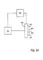
- the analytical apparatus shown in block diagram form in Figure 24 comprises a docking station, referenced 403, of the type shown in Figures 14 and 15 connected to a fluid supply system 45 (also shown in those figures).
- the operation of the fluid supply system 45 is controlled by a controller 400 which is also connected to the docking station 403, and controls the operation of the actuating cylinders 36 and 38, selectively to open and close the mechanism.
- the mechanism has received four cartridges, 404, 406 and 408 and 410, which are clamped in position in the docking station.
- the controller 400 also controls the circuitry on the board 80, so as to drive the sensors in the cartridges, and receives the signals resulting from the oscillation of the sensors, which are then analysed in the controller 400.
Landscapes
- Chemical & Material Sciences (AREA)
- Physics & Mathematics (AREA)
- Health & Medical Sciences (AREA)
- Analytical Chemistry (AREA)
- General Physics & Mathematics (AREA)
- Life Sciences & Earth Sciences (AREA)
- Biochemistry (AREA)
- General Health & Medical Sciences (AREA)
- Acoustics & Sound (AREA)
- Immunology (AREA)
- Pathology (AREA)
- Dispersion Chemistry (AREA)
- Clinical Laboratory Science (AREA)
- Chemical Kinetics & Catalysis (AREA)
- Automatic Analysis And Handling Materials Therefor (AREA)
- Investigating Or Analysing Biological Materials (AREA)
- Sampling And Sample Adjustment (AREA)
Abstract
Description
- This invention relates to a docking station for releasably receiving a cartridge for use in analysing a sample comprising fluid, and to analysing apparatus which includes such a docking station and cartridge.
- The invention is particularly, but not exclusively, applicable o a quartz crystal microbalance system, which uses an electrical-mechanical transducer as a sensor. In such a system, an electrical signal causes the transducer to vibrate.
- The crystal typically has an active surface on which a receptor group is immobilised. That group has a chemical affinity or reactivity towards a substance to be detected or analysed. The substance to be analysed is normally present in a fluid which is bought into contact with the active surface of the crystal. Physical, chemical and biochemical interactions between the receptor group on the active surface and the substance cause a change in the mass attached to the surface (and in other physical properties of the active surface) and these affect the vibrational characteristics, in particular the resonant frequency, of the crystal. Analysis of these effects can be used to obtain qualitative and/or quantitative data on the substance, and its interaction with the receptor.
- This type of analysing apparatus is used in situations, for example to analyse chemical and biochemical interactions, in which it may be desirable to interchange the sensor with another sensor which may be identical to the first sensor or may carry a different receptor group. To that end, it is known to provide the sensor and a flow cell, for bringing the sample into contact with the sensor, in a cartridge which co-operates with a docking station in the analysing apparatus in order to releasably connect inlet and outlet openings for the flow cell to a sample delivery/removal system. The docking station also connects the electrodes on the sensor to driving/measuring circuitry for oscillating the sensor and measuring the frequency of oscillation and/or other characteristics of the oscillation (for example the magnitude of the damping force being experienced by the sensor).
-
US 6,196,059 shows an example of such apparatus. The cartridge comprises an injection moulded body which has an annular rib that surrounds a surface that is to form the base of the flow cell and that includes inlet and outlet openings which communicate with an inlet and outlet of the cartridge through small tubes. The sensor is adhered to the rib which spaces the sensor from the other surface so that the sensor, the surface and the rib between them define the flow cell. The cartridge is received in a docking station that comprises a lid pivotally mounted on a base. The base includes fluid conduits for connecting the inlet and outlet ribs of the cartridge to a sample delivery/removal system, whilst the lid of the mechanism includes an electrical connector for connecting the electrodes of the sensor to the drive/measurement circuitry. Although the connector is described as being spring loaded, it appears to exert enough force on the cartridge to require that the connector engages contacts which are laterally spaced from the sensor so that the electrical connector does not exert a force directly on the sensor. As a result, the cartridge is of a relatively complicated construction having two spaced apart contacts for the electrical connector and wires connecting those contacts to the electrodes on the sensor. - A docking station for a piezoelectric sensor is described in
WO 2004/057319 . - According to the invention, there is provided a docking station for releasably receiving a cartridge for use in analysing a sample comprising a fluid, the cartridge having a flow cell for the sample and an electrically operated sensor for performing said analysis, the docking station comprising a clamping mechanism for urging fluid connector means against the cartridge to provide a fluid connection between the flow cell inlet and sample delivery means; wherein the docking station also comprises an electrical connector for engaging the sensor to connect the latter to electrical circuitry for operating the sensor, the electrical connector being movable, towards and away from the sensor, relative to the clamping mechanism, so that, in use, the electrical connector exerts on the sensor a force which is sufficient to maintain the necessary electrical connection, whilst not being so great as to have a substantial affect on the accuracy of the sensor, characterised in that the station includes earthed pins for forming a Faraday cage around the electrical connector and the sensor, wherein the pins are also operable to locate the cartridge in the station.
- Thus the invention enables the fluid connector to be urged against the cartridge with sufficient force to create a seal with the cartridge, without causing the electrical connector to exert too great a force on the sensor.
- Preferably, the clamping mechanism comprises a carrier member and a co-operating surface, at least one of which is movable towards and away from the other, releasably to compress a cartridge therebetween.
- The carrier member may be attached to a fixed reference surface, and the co-operating surface is movable. In another embodiment, the co-operating surface constitutes the fixed reference surface which locates the cartridge in position in the mechanism, so that the movable member is the carrier member.
- Preferably, the carrier member carries the fluid connector means.
- Preferably, the fluid connector means comprises a connector so sized and shaped as to make mating engagement with a complimentary connector on a cartridge.
- In this case, the fluid connector means of the docking station may conveniently be the male connector.
- This enables the cartridge to have a recessed female connector, and thus to be of a relatively compact construction.
- Preferably, the male fluid connector comprises a tube which is, in use, inserted into a bore in a cartridge received in the docking station. The tube is preferably a ferrule. The fluid connector on the carrier member may to advantage be one of two such connectors for respective connection to an inlet and an outlet of a flow cell of a cartridge.
- The docking station may to advantage include actuation means for automatically closing and opening the clamping mechanism, respectively to clamp and release the cartridge.
- Preferably, the actuation means also acts on the electrical connector automatically to move the connector into and out of engagement with the sensor.
- The carrier member and electrical connector may conveniently be arranged in an opposed relationship so that a cartridge received in the docking station is interposed between the carrier member and the electrical connector.
- Thus the fluid and electrical connections for the sensor are made from opposite sides of the cartridge, so that the cartridge can be of a relatively compact and simple construction.
- In this case, the actuation means preferably comprises a drive assembly which acts between the electrical connector and the carrier member to alter the separation therebetween.
- Where the co-operating surface is interposed between the carrier member and electrical connector, the drive assembly is preferably fixed in position relative to the co-operating surface.
- This allows a single drive assembly to be used to bring both the electrical and fluid connectors into and out of engagement with the cartridge, and for the fluid connector to be urged against the cartridge with a greater force than the electrical connectors. The drive assembly conveniently comprises a hydraulic or pneumatic gas cylinder. Alternatively, the drive assembly includes a motor for driving the electrical connector and carrier member.
- The actuation means is preferably operable to close the clamping mechanism before bringing the electrical connector into engagement with a sensor.
- The clamping mechanism preferably includes a clamping mechanism biasing means for urging the clamping mechanism into a closed position.
- Preferably the docking station includes electrical connector biasing means, weaker than said clamping mechanism biasing means, for urging the electrical connector into engagement with the sensor of a cartridge in the docking station.
- Where the clamping mechanism includes said drive assembly, the clamping mechanism and electrical connector biasing means may form part of the actuating mechanism.
- With this arrangement, the drive assembly is operable only to separate the carrier member and electrical connector from the cartridge, the force with which those components engage the cartridge being determined by the clamping mechanism biasing mean and electrical connector biasing means.
- Thus the drive assembly operates to release a cartridge from the docking station. When a fresh cartridge is inserted, the drive assembly is then deactivated so that it ceases to counteract the effect of the two biasing means. As a result, the clamping mechanism biasing means first urges the carrier member towards the cartridge whilst acting on the electrical connector at least through the driver assembly to prevent the latter from moving towards the cartridge until the cartridge has been engaged by the carrier member. Once this happens, the electrical connector biasing means moves the electrical connector into contact with the sensor.
- Preferably, the electrical connector is mounted on a further carrier member movable relative to a cartridge in the docking station to bring the electrical connector into and out of engagement with the sensor.
- Preferably, the electrical connector biasing means acts on said further carrier member.
- The electrical connector may to advantage be one of two such connectors, each for connecting a respective electrode of the sensor to the circuitry.
- Preferably, the or each electrical connector comprises a spring loaded pin.
- Preferably, the co-operating surface is so arranged as to engage the cartridge to retain the latter in position in the docking station.
- To that end, the co-operating surface may comprise a formation, for example a rib or groove, which is fixed relative to the docking station and which receives an edge portion of a cartridge.
- Said formation may conveniently form part of, or be attached to, a frame of the docking station.
- Preferably, the further carrier member comprises a printed circuit board which may to advantage include interface circuitry for matching the sensor to the circuitry for operating the latter.
- For example, the printed board may carry switching and/or impedance matching circuitry.
- With this arrangement, analytical apparatus equipped with this sort of docking station may be relatively easy modified, by interchanging the printed circuit board with another printed circuit board having interface circuitry of differing characteristics, to be compatible with different types of sensor.
- If the docking station is operable to receive the plurality of cartridges simultaneously, the PCB may additionally include switching circuitry to enable each cartridge in turn to be connected to the circuitry for operating the sensors.
- There is also herein described a docking station for releasably receiving a cartridge for use in analysing a sample comprising a fluid, the cartridge having a sensor for performing said analysis, the docking station comprising opposed first and second carrier members movable in use towards and away from the position to be occupied by a cartridge in the station, and co-operating means for locating the cartridge between the carrier members, the first carrier member carrying a fluid connector for making a fluid connection between the cartridge and a sample delivery means, the second carrier member carrying an electrical connector for connecting the sensor to circuitry for operating the latter, wherein the co-operating surface prevents movement of a cartridge, received by the docking station, in the directions of movement of the carrier members.
- Thus the force applied to the cartridge by the first carrier member clamps the cartridge against the locations without transmitting any substantial amount of force to the second carrier member or electrical connector.
- Preferably, the location means comprises a co-operating surface, such as a rib or groove against which the periphery a cartridge in the docking station is seated.
- The invention also lies in analysing apparatus for analysing samples comprises a fluid, the apparatus comprising a cartridge having an electrically operated sensor for analysing the sample, a docking station as hereinabove described, for releasably receiving the cartridge, sample delivery means for delivering the sample, via the docking station, to the cartridge and electrical circuitry for operating the sensor.
- The cartridge contains a flow cell for bringing the sample into contact with the sensor.
- Preferably, the sensor comprises an electrical-mechanical transducer, for example a piezoelectric, piezomagnetic or acoustic transducer. One example of such a sensor is a quartz crystal microbalance. Other suitable transducers include surface acoustic wave devices, Love wave devices etc.
- The transducers may be provided either in single cartridges, cartridges containing multiple transducers, or as multiple cartridges, either in linear (e.g. 1 x 4) or array configuration (e.g. 4 x 4), or combinations of these two arrangements.
- The cartridge is provided with further apertures through which during the electronic clamping action earthed pins pass. These earthed pins are earthed by contact with an earth rail on the circuit board, and on completion of the clamping action contact an earthed bar of the structure. The function of these earthed pins is to form a "Faraday cage" around the drive pins and electrodes of the sensor. By suitable election of the separation of these earth pins, a means of suppressing the emission of RF signals from the transducer and drive pins can be engaged automatically on closing the clamping action.
- Additionally, these pins locate the cartridge in position in the mechanism.
- The invention will now be described, by way of example only, with reference to the accompanying drawings, in which:
-
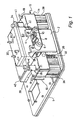
Figure 1 is an isometric view of a first embodiment of a docking station, in accordance with the invention, for an analyser, the station being shown with one cartridge inserted therein, and with its clamping mechanism in its open condition; -
Figure 2 is a similar view of the docking station, but showing two cartridges inserted therein and with the clamping mechanism in its closed condition; -
Figure 3 is simplified sectional front view of the docking station at the stage of operation shown inFigure 4 ; -
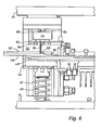
Figure 4 - 6 are sectional side views of part of the docking station ofFigures 1 and2 at successive stages during the operation of the station; -
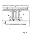
Figures 7 and8 are front sectional views of certain parts of the apparatus ofFigure 3 at the stages of operation shown inFigures 5 and6 respectively; -
Figure 9 is a detailed front sectional view of part of the docking station, showing in particular an electrical connector; -
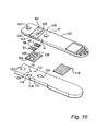
Figure 10 is an exploded perspective view of a cartridge of the apparatus; -
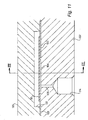
Figure 11 is a sectional side view of the cartridge shown inFigure 10 ; -
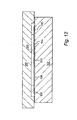
Figure 12 is a sectional end view of the cartridge, taken along the line XII - XII ofFigure 11 ; -
Figure 13 is an isometric view, corresponding toFigure 1 , of a second embodiment of docking station in accordance with the invention; -
Figure 14 is a more detailed view of part of the apparatus shown inFigure 13 ; -
Figure 15 is an isometric view of a third embodiment of docking station in accordance with the invention; -
Figure 16 is an isometric view, from a higher angle, of the third embodiment with four cartridges inserted therein; -
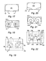
Figure 17 is a view of the underside of the quartz crystal wafer (and the electrode thereon) used in the cartridge ofFigures 10 and11 ; -
Figure 18 is a plan view of the crystal (showing the other electrodes); -
Figure 19 is a view of the underside of the crystal with an adhesive membrane thereon; -
Figures 20-22 are views corresponding toFigures 17 to 19 respectively, of a modified version of crystal, membrane and electrodes; -
Figure 23 compares, graphically, the resistance and Q-Factor of the modified version with the version of sensor shown inFigures 10 and17 to 19 ; and -
Figure 24 is a block diagram of analysing apparatus. - With reference to
Figure 1 , a docking station comprises abase plate 1 from which afront plate 2 rises vertically. At the top of thefront plate 2 there is provided a vertical generallyU-shaped slot 4 at the base of which acartridge location bar 6 is provided. , Thebar 6 extends horizontally across the bottom of theslot 4, and is secured to the plate by means of bolts or rivets at either side of theslot 4. The top of thebar 6 is provided with a pair of parallelhorizontal channels bar 6 co-operates with thebase plate 2 andfront plate 4 to fix the vertical position of the cartridges during the use of the docking station. - Situated immediately behind the
front plate 2 is acarrier member 12 which has twoU-sectioned end portions Figure 1 , and are denoted by reference numerals 18-22. The bolts extend vertically upwards from the base ofactuators carrier member 12. In between the twoend portions Figures 3 - 8 ), which bears fluidic connections for connecting flow cells in the cartridges to a sample delivery/removal system (also described below). - The
carrier member 12 is also slideably mounted on two support and guide posts, one of which is shown at 26, which extend vertically upwards from theplate 1 to anupper plate 30 to support the latter in position in the station. Each of the support posts includes a carrier member biasing means in the form of a respective compression spring such as thespring 32. The other post is shown at 40 inFigure 4 . - The frame of the machine comprises
base plate 1, thefront plate 2 and theupper plate 30. A further carrier member in the form ofplate 34 is situated immediately beneath theplate 30 and includes apertures through which the support and guide posts extend so that the upper carrier plate can move vertically relative to the machine frame. Thecarrier member 12 includesapertures Figure 3 ). The tops of these rods act against the underside of theplate 34. Theupper plate 30 is attached to the instrument frame and provides a reference surface. All plates, carriers the machine frame and the like are constructed of aluminium unless otherwise specified. - The push rods of the cylinders are denoted by
reference numerals Figure 3 , the support and guidepost 26 and corresponding vertical support post 40 (the associated compression spring for which is shown at 42)flank plate portion 44 of thelower carrier member 12. That portion is provided in its upper face with aU-shaped channel 46 which accommodates amicrofluidic manifold 48 forming part of the fluid supply/removal system. The manifold is a microfluidic system for storing, switching and delivering fluids to the cartridge, and is of a general type known from existing instrumentation, and the rest of the system is shown at 45. For example the manifold may comprise a first channel for retaining and supplying samples to the cartridge (under control of an inlet valve) and a further channel for receiving used samples from the cartridge. The manifold 48 communicates withinlet ferrule connectors cartridge 58. The manifold also includes two outlet ferrule connectors (not shown) aligned, in use with outlet connectors (not shown) on the cartridge. - For one or more examples of how ferrules may be used to connect microfluidic systems, reference is made to
WO2004/022233 (Epigem). - The
cartridge 58, when received in the docking station, is located by a channel in thebar 6 and by means of acartridge mounting block 60. Thecartridge mounting block 60 includespassages posts plates block 60 is fixed to these posts and is thus supported in a fixed vertical position relative to thebase plate 1. Theblock 60 includes aslot 66 in its lower surface which is of a substantially T-shaped cross section corresponding to the cross sectional shape of thecartridge 58 so that thecartridge 58 may be slid into and out of theslot 66. The upper surface of theblock 60 includes three vertical bores, 68, 70 and 72 which extend from the top of the block to theslot 66 and which accommodate corresponding electrical connectors in the form of vertical spring loaded gold plated contact pins 74, 76 and 78 which extend vertically down from a printedcircuit board 80 carried on the underside of theupper carrier plate 34. In the present example the contact pins 74, 76 and 78 are coda pins, although other types of spring loaded gold plated contact pins may be used. - With reference to
Figure 4 , theplate 44 also carries a set of earthed, electrically conductive vertical location pins, three of which are denoted bynumerals Figure 14 ). In use, thepins - The upper pins are not visible in the sectional side views (and have been omitted from
Figures 3 ,7 and8 ) for the sake of clarity. However, in the embodiment shown inFigures 13 and14 , one of the pins is shown at 51a. Another upper earth pin 53a andopposed pin 53 are also shown inFigure 14 . Thepin 53 engages the opposite side of the cartridge from thepin 51. - It will be appreciated that the
springs - The
plate 34, and hence thePCB 80 and coda pins, is biased in the downward direction by a pair of compression springs 82 and 84 which function as electrical connector biasing means for the apparatus. Each of thesprings spring location rods plate 34. - The
PCB 80 carries impedance matching and switching circuitry which enables drive/measurement circuitry to operate the sensor in thecartridge 58. In this particular example, the drive/measurement circuitry comprises an oscillator circuit with automatic gain control means such as is described in the present Applicant's UK Patent No.GB 0413134.8 WO00/25118 - The docking station can accept two cartridges side by side. The apparatus thus has two recesses in the cassette mounting block, each for a respective cartridge, two pairs of ferrules on the microfluidic manifold and two sets of three electrical connectors extending from the overhead PCB. These elements are identical to each other, and only one set of the elements has therefore been described. The corresponding reference numerals followed by an apostrophe are used to denote the elements in the other set. For the sake of simplicity only one set of the elements is shown in
Figures 7 and8 . - Referring back to
Figure 3 the threeelectrical connectors pin 74, is shown in more detail inFigure 9 . The coda pin is in the form of an assembly in which a central elongate connectingpin 86 is slideably mounted in aplastics sleeve 88 of, for example, PTFE, PolyAcetal, or Nylon. A downward biasing force is exerted on thepin 86 by acompression spring 90 secured at one end of the inner periphery of thesleeve 88 and at the other to thepin 86.Sleeve 88 helps to locate thepin 86 prior to the latter making connection with atransducer 92 forming part of a cartridge in the docking station. As can also be seen fromFigure 9 , thecartridge mounting block 60 carries a dead stop 94 (another similar stop being provided on the other side of the block 60) for limiting the extent of allowable downward movement of theboard 80. - As is indicated above, the
transducer 92 forms part of a cartridge, which is shown in more detail inFigure 10 . The transducer comprises a quartz crystal plate. The plate is coated on one surface with gold in a pattern that defines a pair ofdrive electrodes Figure 17 ) on the ceiling of the flow cell. The top surface of the plate carries a further gold coating which has two keyhole shapes openings in which the drive electrodes (and their connection strips 99 and 101) are situated, and are spaced from coating 97. Thecoating 97 extends around theedge 103 of the crystal to provide a contact for enabling a coda pin engaging the top surface of the plate to connect to the earth electrode underneath. The common earth electrode on the underside of the crystal carries a binding layer (not shown) for binding with a target substance. - The underside of the
transducer 92 is adhered to the top surface of anadhesive membrane 100 the underside of which is adhered to aplastics plate 102 the upper surface of which constitutes a support surface for thetransducer 92. - The
membrane 100 is a three layered structure comprising a carrier layer of 12 microns thickness sandwiched between upper and lower adhesive layers, each of approximately 36.5 microns thickness. An example of suitable material for the membrane is the double sided adhesive tape sold under the trademark FASTOUCH. Adhesive membranes of various thicknesses, greater or less than 85 microns are available, which can be used to control the height of the flow cell. Themembrane 100 has twoapertures - The shape of the apertures, and hence each flow cell is arranged to provide a suitable profile to ensure laminar flow conditions over the surface, for example the diamond shape illustrated, but other shapes may be designed by those skilled in the art of fluidic design.
- Each of the
apertures respective electrode electrodes membrane 100 spaces thetransducer 92 from the upper surface of theplate 102 so that there is a small gap between each of two said active areas of the quartz crystal and the upper surface of theplate 102, each gap being bounded by the edge of a respective one of the twoapertures plate 102.Passages passages 110 and 112 are outlet passages. Each passage leads onto a female connector, such as theconnectors 114 and 116 which is generally cylindrical and has a tapered end portion, each of the connectors being arranged to receive a respective ferrule of the fluid delivery/removal system. Either or both of the flow cells may be used for the sample to be analysed. Alternatively one may receive the sample, the other a reference solution. - As can be seen from
Figure 10 , the inlet and outlet for each flow cell are located at opposite end regions of the latter. Consequently, a sample introduced into the inlet of the flow cell will flow along the length of the flow cell to the outlet, during which period the sample will interact with the active surface of the crystal and the effect of that interaction will be measured. - As can be seen from
Figure 10 , the flow cells are situated towards one end ofplate 102, towards the other end of which there is provided apatch 118 of the same material as themembrane 100. The purpose of this patch is to help to adhere a top plate 120 (of a plastics material) to thebottom plate 102. Thetop plate 120 includes arecess 122 which, in the assembled cartridge, accommodates thesensor 92 so that the latter makes no contact with theplate 120. Themembrane 100, however, does extend beyond the boundaries of therecess 122 so as to adhere the twoplates - As well as securing the
transducer 92 in position and defining each flow cell, themembrane 100 provides a suitable seal, by virtue of the adhesive layers, for preventing fluid escaping from the flow cells. - The
upper plate 120 includes throughbores electrodes transducer 92. Notches H in the upper plate serve to provide an initial location of the cartridge in the docking station as will be described below. - The two
plates bore 127 in theplate 120 being in line with thebore 130 inplate 102, thebore 128 with thebore 129 so that there are two large bore through passages in the cartridge housing (defined by theplates 102 and 120). These passages, in use, accept electrically conductive lateral location pins (e.g 47,49) of the docking station for assisting in the correct location of the cartridge. The lateral location pins when extended into and past the cartridge engage opposed earth pins on thecircuit board 80, and thus also to act as a Farraday cage around the drive Coda pins and electrodes of the sensor. The spacing between the pins is chosen, based on the frequency of the drive signal to the sensor, to achieve that end. - Before a cartridge is inserted into the docking station, the hydraulic/
pneumatic cylinders upper carrier plate 34 andlower carrier member 12 away from each other against action of thesprings ferrules slot 66 in thecartridge mounting block 60 so that a cartridge can be inserted into the latter. This thus puts the docking station into a condition in which a cartridge can be received or removed.Figures 1 ,3 and4 illustrate the docking station when in that condition. - The
cartridge 58 is then slid into one of thechannels cassette location bar 6, and is moved into theslot 66 until the inboard end of thecartridge 58 abuts the end of the slot. It will be appreciated that the docking station for the cartridge shown inFigure 10 will have a sufficient number of electrical and fluidic connectors to provide electrical/fluid connection to both flow cells in the cartridge. - After a cartridge has been inserted into the docking station, the pressure in the fluid (hydraulic or pneumatic) being used to extend the
cylinder carrier member 12 andplate 34. As a result, the movement of theplate 34 andmember 12 is determined by the action of thesprings springs springs springs plate 44, and theshafts cylinders 36 and 38) to retain theplate 34 in its retracted position. However, at the same time as thecylinders springs carrier member 12 upwards towards thecartridge mounting block 60.. This movement continues (whilst theplate 34 remains stationary) until the ferrules on thefluidic manifold 48 engage the female fluid connectors in the bottom plate of the cartridge. Thesprings - This condition is illustrated in the docking station shown in
Figure 4 and in the simplified schematic arrangement ofFigure 7 . Theplate 44 engages theblock 60 so that further upward movement of theplate 44 is prevented. At this stage, thesprings plate 32 through thecylinders plate 34, and hence thePCB 80 and the coda pins 74, 76 and 78, moves down towards the cartridge under the action ofsprings plate 34 continues to move down until the downward movement of thecarrier plate 34 is prevented by contact with the base of atransverse slot 59 in the mountingblock 60. The height of this slot is selected to ensure that the good contact is made by the spring loaded coda pins on the sensor, and acts as thedead stop 94 shown infigure 9 . This condition of the station is shown inFigures 2 ,6 and8 . - Since the cartridge is located separately from the
plate plate 44 on the cartridge (to obtain a fluid seal), does not result in any large reaction force between the coda pins and the transducer. Thus the invention enables an effective and reliable fluid seal to be provided without exerting large forces on the transducer. - The embodiment of docking station shown in
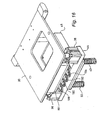
Figure 13 is similar in many respects to the embodiment shown inFigures 1-9 . Therefore, inFigure 13 , components corresponding to those shown inFigure 1 - 9 are denoted by the same reference numerals as are used in those figures. InFigures 13 and14 theblock 60 has been omitted to enable the electronic contacts to be shown. The station has two pneumatic/hydraulic actuator cylinders corresponding tocylinders cylinder 36 has been omitted fromFigure 13 to enable thepost 26 andspring 32 to be seen. In addition the mountingplate 34 whilst present in this embodiment, has been omitted fromFigure 14 for the sake of clarity. - In the first embodiment, the
carrier member 12 comprises a sub-assembly of twoU-shaped end portions central plate portion 44 is bolted. In theFigure 13 embodiment, however, the sub-assembly has been replaced by a single flat plate referenced 12/44a, the end regions of which are denoted byreference numerals 14 and 16 (but are not U-shaped). Each actuator cylinder has a body which is attached to the underside of theplate 12/44a by means of four vertical bolts, one of which is shown at 20 inFigure 13 . - In the embodiment shown in
fig 13 and14 the carrier member (i.e. the mounting plate 34) is mounted on slidable bushes B1 and B2 which run onrods plate 34 and hold the spring in its compressed state, againstplate 30. Various rods R1-5 are used to precision align thecarrier plate 34 with respect to block 60 Stub pin P is one of several similar (others not shown) to precision attach thePCB 80 to plate 34 ,i.e. to define a fixed vertical distance betweenplate 34 and thePCB 80. - To assist location of the cartridge a
screw 150 comprising an internally spring loadedball bearing 150a is aligned to locate with notches H in the side of the cartridge and provide positive feedback to the user that the cartridge is properly located. - Screw connectors N1 and N2 attach plate L to the
block 60. Plate L is fixed with respect to the frame. This plate provides a continuation of the T shapedchannels bar 6 into the docking station (i.e. mechanism).Upper plate 30 comprises two parts, alower part 30a and anupper part 30b, which face each other along a longitudinal phase. Infig 14 thepart 30a has been removed. In this embodiment a peltier cooling device E is located on top of 30b and in good thermal contact with it. This assists in dissipating heat generated on thePCB 80. Screw connections M1 and M2 connect 30a and 30b and allow theplate 30b in turn to be attached to an exterior frame plate. Stub pin T and a corresponding one on the other side of the 30b precision space theplate 30b from an external cover to allow for the thickness of the cooling device E. - Other parts visible in
figs 13 and14 include electrical connectors C to thePCB 80. - The embodiment of docking station shown in
Figures 15 and16 is operable to receive four cartridges of the type described above, and is thus for use with an eight channel analyser (two channels per cartridge). - This embodiment of docking station has numerous features which correspond to features of the other two embodiments of docking station, and are therefore denoted by the same reference numerals as have been used in relation to the other embodiments. Thus, for example, the third embodiment has two hydraulic or
pneumatic actuating cylinders lower plate 44 carrying ferrules and fluid supply manifold and aupper plate 34 which carries thePCB 80. In this case, however, the bases of theactuating cylinders plate 44. - The
cylinders reference plate 151 attached to a frame of the machine that includes thebase plate 1 and the upper plate 30 (Figure 16 ). The underside of thereference plate 150 carries five vertical, parallel plastics strips 151 - 155. The opposing sides of adjacent strips carry grooves for accepting cartridges so that the apparatus accept four cartridges, each retained in the grooves between a respective neighbouring pair of the strips. Theplate 151 also includes four slots 156 - 159 through which a respective group of three electrodes extend so as to be able to contact the terminals on a crystal in a cartridge under theplate 151. One group of the electrodes is denoted by thereference numerals Figures 15 and16 , thecircuit board 80 by which the immediate connection to the crystal is made is entirely passive. The active components for driving and sensing the crystals have been removed to the second upper circuit board 161 positioned above theboard 80. The upper board carries four sets of three electrical connectors, generally referenced 160, 162, 164 and 166 which provide connections between the electrical connectors on thelower board 80 and a separate analyser (not shown) for providing the power to drive the crystals in the cartridges and analysing the resultant signals. Thus 176 and 176b are the active drive connections to theboard - The upper board also carries
earth connectors passive board 80 is mounted to the upper active board by metal connecting pins, K1-3. These are also earthed on both the upper and lower boards, and together with theearth connectors 168, etc form a Faraday cage around the driving connectors between the two boards. The Faraday cage around the cartridges is formed by the earth pins and cartridge locating pins, as with the other embodiments. - The
assembly 44 comprises a mountingsection 45 for housing the microfluidic manifold, made of Acetal plastic. The manifold is located in an aluminium insert A to provide rigidity and thermal control under the cover plate D. The manifold connects the micro fluid delivery system to the eight pairs of ferrule connectors (not shown), and hence to the four flow cells of the cartridges in the docking station. - Each of the support posts 26 and 40 is of a stepped construction, and only this aspect of the
support post 40 will be described. That post has an enlarged diameterlower portion 180 separated from a further, upperenlarged diameter portion 182 by a reduceddiameter portion 184. Thecompression spring 42 acts between thebase plate 1 and the underside of theplate 44, which is slideably mounted on the reduceddiameter portion 184, so that the spring exerts an upward biasing force on theplate 44. The upper surface of thereference plate 151 is attached to theenlarged diameter portion 182 and thus to the frame of the machine. - The top of the
post 40 has a further reduceddiameter portion 186 which extends through anaperture 188 in theplate 34. That aperture contains a radially inwardly directed flange (not visible) which is of an inner diameter slightly larger than that of theportion 186 and which provides a shoulder for a spring (corresponding to spring 84) which acts between the shoulder and the underside of thetop plate 30 to exert a downward biasing force on theplate 34. For the sake of clarity all of the springs have been omitted fromFigure 15 , although thesprings Figure 16 (from which thebase plate 1 andcolumns - The operation of the docking station is similar to that of the other embodiments described above. More specifically, the cartridges are inserted into the spaces between the strips 151 - 155, while the
actuators Figure 15 . The four cartridges are shown at 188, 190, 192 and 194 inFigure 16 , and are orientated with the openings for the electrical contact pins uppermost and the female fluidic connectors on their underside. The cartridges are located by sliding into opposed recesses (one of which is denoted C' inFig 15 ) located on the sides of strips 151-155. Part way down these recesses are located spring loaded ball bearings which locate in the notches H in the side of the cartridge as it is pushed into the recess, and so positively locates the cartridge. The actuators are then retracted, causing thesprings 32 and 42 (which are stronger than the springs acting on the plate 34) to move theplate 44 up against the underside of the cartridges so that, initially, the fluidic connections are established. As theactuators plates plate 34 downwards so that the Coda pins engage the electrical contacts on the quartz crystals in the cartridges and so that the earthed upper pins engage the corresponding, aligned earthed lower pins (e.g. 49 and 47) to create a respective Faraday cage around each cartridge. - The embodiment of sensor (shown in
Figures 17 - 19 ) has a dualchannel sensing plate 92 of quartz which carries an active gold layer on either side. The biochemically active side of the sensor coated with a continuous coating of gold and is connected to earth. The electrically driven side has a pattern in which the active areas (96 and 98) are circular, with contiguousrectangular areas earth electrode 97 which forms a respective ring around each driven circular area and serves to dampen any electrical cross-talk between the two or more resonators. - In use, the electrical drive applied to the circular electrodes (through the rectangular areas) causes the quartz plate to resonate. This resonance occurs where the electrically driven electrode opposes the ground plate electrode. Conventionally, this causes a transfer shear mechanical mode to be set up under the circular areas of the driven electrodes.
- Applicants have discovered, however, that the presence of the drive signal in the rectangular areas can cause the plate under these areas also to oscillate where the ground plain also opposes the rectangular areas. More particularly, with reference to
Figure 19 (which shows the overlay between the adhesive membrane and the electrodes), the region of each rectangular electrode between the edge of theearth electrode 105 and the edge of the flow cell (e.g. the shaded area S inFigure 19 ) can give rise to oscillations which can either be reflected off the edge of thecrystal 92 or place stresses on the crystal (by virtue of the restraining effect of the adhesive membrane). These effects can vary over time, be hard to predict and therefore are detrimental to the accuracy of the instrument. - The effects are at least mitigated by the spacing of the bottom portion of the electrode 105 (as viewed in
Figure 17-19 ) from the bottom of thecrystal 92 so that there is at least an area G at the edge of the crystal where the rectangular portions do not overlap the earth electrode and therefore do not cause the unwanted vibrations. - An improved version of the sensor (forming part of the cartridge) shown in
Figures 20 - 22 will now be described. - The improved resonator design shown in
Figures 20 - 22 has many features in common with or corresponding to those of the design shown inFigure 7-19 , and these are denoted by the reference numerals used inFigure 7-19 raised by 200. - In this case, further portions of the
earth electrode 205 have been removed where these overlap with therectangular areas membrane 300 touches thecrystal plate 292. Thus the area of crystal under the rectangular portions and in contact with the adhesive membrane does not significantly oscillate when the sensor is driven. As a result, the resistance of the quartz plate at resonance is not affected by damping caused by the presence of the membrane contacting this area, and a lower resistance and higher Q factor are achieved. - These improvements are illustrated in the graph of
Figure 23 , in which the left-hand column of each graph shows the resistance or, as the case may be, Q factor of the first embodiment sensor, whilst the right hand column of each graph shows a corresponding measurement for the improved version. - As can be seen from
Figure 22 , thelower edges electrode 205, i.e. the edges which extend across therectangular portions adjacent edge - The result of the improvements discussed above is that the sensor, when used in contact with a liquid, has reduced noise and improved unit to unit variance. Additionally, it has been found that the elastic properties of some adhesives may change with time, and that this can give rise to slow changes in the damping of the resonator if substantial portions of the crystal under the membrane are vibrated. This is also undesirable as it leads to baseline drift. With the improved design, the changes in the elastic or mechanical properties of the adhesive or the membrane have a much reduced effect. This can contribute to improved baseline stability and drift which is important in certain types of biochemical assay.
- The improvements are optimised when the edge of the membrane does not overlap the edge of the modified electrode boundary at all. However, improvements over the earlier design are also achieved where there is a significant reduction of overlap. It is desirable not to extend a flow cell boundary too far outside the electrode boundary because this exposes uncoated quartz to the analyte fluid. This may result in nonspecific absorption of coatings and the like to the quartz which is undesirable.
- It can also be seen from
Figures 21 and 22 that the outboard ends 358 and 360 of the rectangular portions are of an enlarged width. This improves the tolerance of the analytical apparatus to changes in alignment between the Coda pins and the electrodes. - The analytical apparatus shown in block diagram form in
Figure 24 comprises a docking station, referenced 403, of the type shown inFigures 14 and15 connected to a fluid supply system 45 (also shown in those figures). The operation of thefluid supply system 45 is controlled by acontroller 400 which is also connected to thedocking station 403, and controls the operation of theactuating cylinders Figure 24 , the mechanism has received four cartridges, 404, 406 and 408 and 410, which are clamped in position in the docking station. Thecontroller 400 also controls the circuitry on theboard 80, so as to drive the sensors in the cartridges, and receives the signals resulting from the oscillation of the sensors, which are then analysed in thecontroller 400.
Claims (28)
- A docking station for releasably receiving a cartridge (58) for use in analysing a sample comprising a fluid, the cartridge (58) having a flow cell for the sample and an electrically operated sensor (92, 292) for performing said analysis, the docking station comprising a clamping station (12, 6, 60) for urging fluid connector means (44) against the cartridge (58) to provide a fluid connection between the flow cell inlet and sample delivery means; the docking station also comprising an electrical connector (74) for engaging the sensor (92; 292) to connect the latter to electrical circuitry for operating the sensor (92; 292), the electrical connector (74) being movable, towards and away from the sensor, relative to the clamping station, so that, in use, the electrical connector exerts on the sensor a force which is sufficient to maintain the necessary electrical connection, whilst not being so great as to have a substantial detrimental effect on the accuracy of the sensor (92; 292), characterised in that the station includes earthed pins (47, 49, 51) for forming a Faraday cage around the electrical connector and the sensor, wherein, the earthed pins (47, 49, 51) are also operable to locate the cartridge (58) in the position in the station.
- A docking station according to claim 1, in which the clamping station comprises a carrier member (12) and a co-operating surface (6, 10), at least one of which is movable towards and away from the other, releasably to compress a cartridge (58) therebetween.
- A docking station according to claim 2, in which the carrier member (12) carries the fluid connector means (44).
- A docking station according to claim 3, in which the fluid connector means (44) comprises a connector (50, 52) so sized and shaped as to make mating engagement with a complementary connector on a cartridge.
- A docking station according to claim 4, in which the fluid connector means (50, 52) of the docking station is the male connector.
- A docking station according to claim 5, in which the male fluid connector comprises a tube (50, 52) which is, in use, inserted into a bore in a cartridge received in the docking station.
- A docking station according to claim 6, in the tube is a ferrule (50, 52).
- A docking station according to any of claims 3 to 7, in which the fluid connector on the carrier member is one of two such connectors (50, 52) for respective connection to an inlet and an outlet of a flow cell of a cartridge.
- A docking station according to any of claims 2 to 8, in which the carrier member (12) and electrical connector (74) are arranged in an opposed relationship so that a cartridge received in the docking station is interposed between the carrier member (12) and the electrical connector (74).
- A docking station according to any of claims 2 to 9, in which the docking station includes actuation means (36, 38, 32, 42) for automatically closing and opening the clamping station, respectively to clamp and release the cartridge (58).
- A docking station according to claim 10, in which the actuation means (36, 38, 32, 42) also acts on the electrical connector automatically to move the connector into and out of engagement with the sensor (58).
- A docking station according to claim 11, when dependent on claim 2, in which the actuation means comprises a drive assembly (36, 38) which acts between the electrical connector (74) and the carrier member (12) to alter the separation therebetween.
- A docking station according to claim 12, in which the co-operating surface (6, 60) is interposed between the carrier member (12) and electrical connector (74), and in which the drive assembly (36, 38)is fixed in position relative to the co-operating surface.
- A docking station according to claim 12 or claim 13, in which the drive assembly comprises a hydraulic or pneumatic gas cylinder (36, 38).
- A docking station according to any of claims 11 to 13, in which the actuation means is operable to close the clamping station (12, 6, 60) before bringing the electrical connector (74) into engagement with a sensor (92; 292).
- A docking station according to any of the preceding claims, in which the clamping station (12, 6, 60) includes a clamping station biasing means (32, 42) for urging the clamping station into a closed position.
- A docking station according to claim 16, in which the docking station includes electrical connector biasing means (82, 84), weaker than said clamping station biasing means (32, 42), for urging the electrical connector into engagement with the sensor of a cartridge (58) in the docking station.
- A docking station according to either of claims 16 and 17, when appended to claim 12, in which the clamping station (12, 6, 60) and electrical connector biasing means (82, 84) form part of the actuation means.
- A docking station according to claim 18, in which the electrical connector (74) is mounted on a further carrier member (34) movable relative to cartridge (58) in the docking station to bring the electrical connector (74) into and out of engagement with the sensor (92; 292).
- A docking station according to claim 19, in which the electrical connector biasing means (82, 84) acts on said further carrier member (34), to urge the latter and hence the electrical connector (74) towards the sensor (92, 292) of a cartridge (58) in the docking station.
- A docking station according to claim 19 or claim 20, in which the carrier member (12) and further carrier member (34) are opposed to each other and are moveable, in use, towards and away from the position to be occupied by a cartridge (58) in the docking station, wherein the cooperating surface (6, 60) is so arranged as to engage the cartridge (58) to retain the latter in position in the docking station, thereby to prevent movement of the cartridge (58) in the directions of movement of the carrier members (12, 34).
- A docking station according to any of the preceding claims, in which the electrical connector (74) is one of two such connectors (74, 76), each for connecting a respective electrode of the sensor to the circuitry.
- A docking station according to any of the preceding claims, in which the or each electrical connector comprises a spring loaded pin.
- A docking station according to any of claims 21 to 23, in which the co-operating surface (6, 60) comprises a formation which is fixed relative to the docking station and which receives an edge portion of a cartridge.
- A docking station according to claim 24, in which said formation forms part of, or is attached to, a frame (1, 2, 30) of the docking station.
- A docking station according to claim 19, in which the further carrier member (34) comprises a printed circuit board (80) which includes interface circuitry for matching the sensor (92; 292) to the circuitry for operating the latter.
- Apparatus for analysing samples comprising a fluid, the apparatus comprising a cartridge (58) having an electrically operated sensor (92; 292) for analysing the sample and a flow cell for brining the sample into contact with the sensor, a docking station according to any of the preceding claims, for releasably receiving the cartridge (58), sample delivery means for delivering the sample, via the docking station, to the cartridge and electrical circuitry for operating the sensor.
- Apparatus according to claim 27, in which the sensor (92; 292) comprises an electrical-mechanical transducer.
Applications Claiming Priority (3)
| Application Number | Priority Date | Filing Date | Title |
|---|---|---|---|
| GB0506711A GB0506711D0 (en) | 2005-04-01 | 2005-04-01 | Docking mechanism |
| GB0515757A GB0515757D0 (en) | 2005-07-30 | 2005-07-30 | Docking mechanism |
| PCT/GB2006/001164 WO2006103440A2 (en) | 2005-04-01 | 2006-03-31 | Docking mechanism for a sensor cartridge |
Publications (2)
| Publication Number | Publication Date |
|---|---|
| EP1864120A2 EP1864120A2 (en) | 2007-12-12 |
| EP1864120B1 true EP1864120B1 (en) | 2011-11-30 |
Family
ID=36930172
Family Applications (1)
| Application Number | Title | Priority Date | Filing Date |
|---|---|---|---|
| EP06726570A Expired - Lifetime EP1864120B1 (en) | 2005-04-01 | 2006-03-31 | Docking station for a sensor cartridge |
Country Status (4)
| Country | Link |
|---|---|
| US (1) | US7980149B2 (en) |
| EP (1) | EP1864120B1 (en) |
| AT (1) | ATE535799T1 (en) |
| WO (1) | WO2006103440A2 (en) |
Cited By (1)
| Publication number | Priority date | Publication date | Assignee | Title |
|---|---|---|---|---|
| DE102022207709A1 (en) | 2022-07-27 | 2024-02-01 | Robert Bosch Gesellschaft mit beschränkter Haftung | Hydraulic drive device for an analysis device for analyzing a sample contained in a cartridge, analysis device and method for operating a hydraulic drive device |
Families Citing this family (18)
| Publication number | Priority date | Publication date | Assignee | Title |
|---|---|---|---|---|
| EP2167233B1 (en) * | 2007-06-26 | 2013-01-23 | Micronit Microfluidics B.V. | Device and method for fluidic coupling of fluidic conduits to a microfluidic chip, and uncoupling thereof |
| US8640555B2 (en) | 2009-02-09 | 2014-02-04 | Bioaccel | Performance |
| CA3016967C (en) | 2010-04-16 | 2021-08-31 | Opko Diagnostics, Llc | Systems and devices for analysis of samples |
| USD645971S1 (en) | 2010-05-11 | 2011-09-27 | Claros Diagnostics, Inc. | Sample cassette |
| CN103477230B (en) * | 2010-08-27 | 2016-03-02 | 亚利桑那大学董事会 | Improvements related to the performance of analyzers for biological samples |
| TWM404975U (en) * | 2010-11-22 | 2011-06-01 | Apex Biotechnology Corp | Holding device for apparatus having the same |
| US8486717B2 (en) | 2011-01-18 | 2013-07-16 | Symbolics, Llc | Lateral flow assays using two dimensional features |
| US9874556B2 (en) | 2012-07-18 | 2018-01-23 | Symbolics, Llc | Lateral flow assays using two dimensional features |
| CN107051604B (en) * | 2012-08-30 | 2019-07-05 | 生命技术公司 | Vertical grip device |
| FR3002637A1 (en) * | 2013-02-25 | 2014-08-29 | Bigot Jerome Le | Gas-detector for detecting gas odors to e.g. detect drifts in manufacturing process, has connector placed on end connector to electrically connect sensor to board, where end connector receives connector by presenting convergent form |
| WO2015038978A1 (en) | 2013-09-13 | 2015-03-19 | Symbolics, Llc | Lateral flow assays using two dimensional test and control signal readout patterns |
| GB2520523B (en) * | 2013-11-22 | 2016-09-21 | Tidal Generation Ltd | Subsea cable engagement system |
| EP3104976B1 (en) | 2014-02-14 | 2018-07-25 | Elements S.r.l. | High sensitivity multichannel detection device |
| EP3281004A1 (en) | 2015-04-06 | 2018-02-14 | Göksen Göksenin Yaralio Lu | Dev ice and method for measuring physical properties of a material |
| USD804682S1 (en) | 2015-08-10 | 2017-12-05 | Opko Diagnostics, Llc | Multi-layered sample cassette |
| CN108348917B (en) * | 2015-09-09 | 2020-06-09 | 生命技术公司 | Clamping device for receiving cartridge and method of using the same |
| CA3198157A1 (en) | 2020-12-21 | 2022-06-30 | Conservation X Labs, Inc. | Systems and methods using hand-held devices for detecting a target analyte loaded on a cartridge |
| CN116124571B (en) * | 2022-11-18 | 2024-02-09 | 北京聚仪共享科技有限公司 | Printed circuit board pull-out strength tester |
Family Cites Families (8)
| Publication number | Priority date | Publication date | Assignee | Title |
|---|---|---|---|---|
| US6196059B1 (en) * | 1997-08-11 | 2001-03-06 | Fraunhofer Gesellschaft Zur Forderung Der Angewandten Forschung E.V. | Piezoelectric resonator, process for the fabrication thereof including its use as a sensor element for the determination of the concentration of a substance contained in a liquid and/or for the determination of the physical properties of the liquid |
| WO2002012873A2 (en) | 2000-08-08 | 2002-02-14 | Smithkline Beecham P.L.C. | Quartz crystal microbalance |
| AU2002360822A1 (en) * | 2001-12-17 | 2003-06-30 | Aclara Biosicences, Inc. | Microfluidic analytical apparatus |
| ES2282726T3 (en) | 2002-09-06 | 2007-10-16 | Epigem Limited | MODULAR MICROFLUIDIC SYSTEM. |
| SE0203772D0 (en) * | 2002-12-19 | 2002-12-19 | Attana Ab | Piezoelectric sensor arrangement |
| US6990852B2 (en) | 2003-07-28 | 2006-01-31 | Becton Dickinson & Company | System and method for detecting particles |
| US20090061450A1 (en) * | 2006-03-14 | 2009-03-05 | Micronics, Inc. | System and method for diagnosis of infectious diseases |
| WO2010088514A1 (en) * | 2009-01-30 | 2010-08-05 | Micronics, Inc. | Portable high gain fluorescence detection system |
-
2006
- 2006-03-31 US US11/817,853 patent/US7980149B2/en active Active
- 2006-03-31 AT AT06726570T patent/ATE535799T1/en active
- 2006-03-31 EP EP06726570A patent/EP1864120B1/en not_active Expired - Lifetime
- 2006-03-31 WO PCT/GB2006/001164 patent/WO2006103440A2/en not_active Ceased
Cited By (1)
| Publication number | Priority date | Publication date | Assignee | Title |
|---|---|---|---|---|
| DE102022207709A1 (en) | 2022-07-27 | 2024-02-01 | Robert Bosch Gesellschaft mit beschränkter Haftung | Hydraulic drive device for an analysis device for analyzing a sample contained in a cartridge, analysis device and method for operating a hydraulic drive device |
Also Published As
| Publication number | Publication date |
|---|---|
| US7980149B2 (en) | 2011-07-19 |
| WO2006103440A3 (en) | 2006-11-30 |
| ATE535799T1 (en) | 2011-12-15 |
| WO2006103440A2 (en) | 2006-10-05 |
| EP1864120A2 (en) | 2007-12-12 |
| US20090114044A1 (en) | 2009-05-07 |
Similar Documents
| Publication | Publication Date | Title |
|---|---|---|
| US7980149B2 (en) | Docking mechanism for a sensor cartridge | |
| US7963151B2 (en) | Cartridge for a fluid sample analyser | |
| US20100210008A1 (en) | Configurable Microfluidic Substrate Assembly | |
| US6165417A (en) | Integrated titer plate-injector head for microdrop array preparation, storage and transfer | |
| EP0579997B1 (en) | Disposable cartridge for ion selective electrode sensors | |
| US7892493B2 (en) | Fluid sample transport device with reduced dead volume for processing, controlling and/or detecting a fluid sample | |
| US20110318840A1 (en) | Fluidic cartridge for detecting chemicals in samples, in particular for performing biochemical analyses | |
| CN102448611B (en) | Device and method for controlling fluid flows in lab-on-a-chip systems and method for producing said device | |
| US20110000280A1 (en) | Dry Side Sensor Mounting for Sensor Chip Assembly | |
| US6386219B1 (en) | Fluid handling system and method of manufacture | |
| US9227189B2 (en) | Microfluidic liquid stream configuration system | |
| WO2004057319A1 (en) | Piezoelectric sensor arrangement | |
| JP2004093558A (en) | Analysis chip, analysis chip unit, analysis device, and method of manufacturing analysis chip | |
| US20020025582A1 (en) | Methods and devices for storing and dispensing liquids | |
| AU2001283977A1 (en) | Quartz crystal microbalance | |
| US7487682B2 (en) | Measuring cell as well as constructing methods for a measuring cell and measuring apparatus with a mount for such a measuring cell | |
| KR101737121B1 (en) | Microfluidic system | |
| US7204961B2 (en) | Liquid feed apparatus and automatic analyzing apparatus | |
| US20100233032A1 (en) | Cartridge For A Fluid Sample Analyser | |
| EP3710790A1 (en) | Sensor assembly and method of using same | |
| US8241589B2 (en) | Flow cell | |
| JP5192073B2 (en) | Microreactor and microreactor system | |
| US20240001359A1 (en) | Microfluidic analyser for in-vitro biosensing and diagnostics | |
| KR20250032833A (en) | Sample seperating device and well plate, sample reaction device and sensor device for field diagnosing using the sample seperating device | |
| US20100028206A1 (en) | Microchip and method of manufacturing microchip |
Legal Events
| Date | Code | Title | Description |
|---|---|---|---|
| PUAI | Public reference made under article 153(3) epc to a published international application that has entered the european phase |
Free format text: ORIGINAL CODE: 0009012 |
|
| 17P | Request for examination filed |
Effective date: 20070901 |
|
| AK | Designated contracting states |
Kind code of ref document: A2 Designated state(s): AT BE BG CH CY CZ DE DK EE ES FI FR GB GR HU IE IS IT LI LT LU LV MC NL PL PT RO SE SI SK TR |
|
| 17Q | First examination report despatched |
Effective date: 20080317 |
|
| DAX | Request for extension of the european patent (deleted) | ||
| RAP1 | Party data changed (applicant data changed or rights of an application transferred) |
Owner name: INVERNESS MEDICAL SWITZERLAND GMBH |
|
| RAP1 | Party data changed (applicant data changed or rights of an application transferred) |
Owner name: ALERE SWITZERLAND GMBH |
|
| RTI1 | Title (correction) |
Free format text: DOCKING STATION FOR A SENSOR CARTRIDGE |
|
| GRAP | Despatch of communication of intention to grant a patent |
Free format text: ORIGINAL CODE: EPIDOSNIGR1 |
|
| GRAS | Grant fee paid |
Free format text: ORIGINAL CODE: EPIDOSNIGR3 |
|
| GRAA | (expected) grant |
Free format text: ORIGINAL CODE: 0009210 |
|
| AK | Designated contracting states |
Kind code of ref document: B1 Designated state(s): AT BE BG CH CY CZ DE DK EE ES FI FR GB GR HU IE IS IT LI LT LU LV MC NL PL PT RO SE SI SK TR |
|
| REG | Reference to a national code |
Ref country code: CH Ref legal event code: EP Ref country code: GB Ref legal event code: FG4D |
|
| REG | Reference to a national code |
Ref country code: IE Ref legal event code: FG4D |
|
| REG | Reference to a national code |
Ref country code: DE Ref legal event code: R096 Ref document number: 602006026146 Country of ref document: DE Effective date: 20120301 |
|
| REG | Reference to a national code |
Ref country code: NL Ref legal event code: VDEP Effective date: 20111130 |
|
| LTIE | Lt: invalidation of european patent or patent extension |
Effective date: 20111130 |
|
| PG25 | Lapsed in a contracting state [announced via postgrant information from national office to epo] |
Ref country code: LT Free format text: LAPSE BECAUSE OF FAILURE TO SUBMIT A TRANSLATION OF THE DESCRIPTION OR TO PAY THE FEE WITHIN THE PRESCRIBED TIME-LIMIT Effective date: 20111130 Ref country code: IS Free format text: LAPSE BECAUSE OF FAILURE TO SUBMIT A TRANSLATION OF THE DESCRIPTION OR TO PAY THE FEE WITHIN THE PRESCRIBED TIME-LIMIT Effective date: 20120330 |
|
| PG25 | Lapsed in a contracting state [announced via postgrant information from national office to epo] |
Ref country code: GR Free format text: LAPSE BECAUSE OF FAILURE TO SUBMIT A TRANSLATION OF THE DESCRIPTION OR TO PAY THE FEE WITHIN THE PRESCRIBED TIME-LIMIT Effective date: 20120301 Ref country code: LV Free format text: LAPSE BECAUSE OF FAILURE TO SUBMIT A TRANSLATION OF THE DESCRIPTION OR TO PAY THE FEE WITHIN THE PRESCRIBED TIME-LIMIT Effective date: 20111130 Ref country code: BE Free format text: LAPSE BECAUSE OF FAILURE TO SUBMIT A TRANSLATION OF THE DESCRIPTION OR TO PAY THE FEE WITHIN THE PRESCRIBED TIME-LIMIT Effective date: 20111130 Ref country code: SI Free format text: LAPSE BECAUSE OF FAILURE TO SUBMIT A TRANSLATION OF THE DESCRIPTION OR TO PAY THE FEE WITHIN THE PRESCRIBED TIME-LIMIT Effective date: 20111130 Ref country code: NL Free format text: LAPSE BECAUSE OF FAILURE TO SUBMIT A TRANSLATION OF THE DESCRIPTION OR TO PAY THE FEE WITHIN THE PRESCRIBED TIME-LIMIT Effective date: 20111130 Ref country code: SE Free format text: LAPSE BECAUSE OF FAILURE TO SUBMIT A TRANSLATION OF THE DESCRIPTION OR TO PAY THE FEE WITHIN THE PRESCRIBED TIME-LIMIT Effective date: 20111130 Ref country code: PT Free format text: LAPSE BECAUSE OF FAILURE TO SUBMIT A TRANSLATION OF THE DESCRIPTION OR TO PAY THE FEE WITHIN THE PRESCRIBED TIME-LIMIT Effective date: 20120330 |
|
| PG25 | Lapsed in a contracting state [announced via postgrant information from national office to epo] |
Ref country code: CY Free format text: LAPSE BECAUSE OF FAILURE TO SUBMIT A TRANSLATION OF THE DESCRIPTION OR TO PAY THE FEE WITHIN THE PRESCRIBED TIME-LIMIT Effective date: 20111130 |
|
| PG25 | Lapsed in a contracting state [announced via postgrant information from national office to epo] |
Ref country code: DK Free format text: LAPSE BECAUSE OF FAILURE TO SUBMIT A TRANSLATION OF THE DESCRIPTION OR TO PAY THE FEE WITHIN THE PRESCRIBED TIME-LIMIT Effective date: 20111130 Ref country code: EE Free format text: LAPSE BECAUSE OF FAILURE TO SUBMIT A TRANSLATION OF THE DESCRIPTION OR TO PAY THE FEE WITHIN THE PRESCRIBED TIME-LIMIT Effective date: 20111130 Ref country code: SK Free format text: LAPSE BECAUSE OF FAILURE TO SUBMIT A TRANSLATION OF THE DESCRIPTION OR TO PAY THE FEE WITHIN THE PRESCRIBED TIME-LIMIT Effective date: 20111130 Ref country code: CZ Free format text: LAPSE BECAUSE OF FAILURE TO SUBMIT A TRANSLATION OF THE DESCRIPTION OR TO PAY THE FEE WITHIN THE PRESCRIBED TIME-LIMIT Effective date: 20111130 Ref country code: BG Free format text: LAPSE BECAUSE OF FAILURE TO SUBMIT A TRANSLATION OF THE DESCRIPTION OR TO PAY THE FEE WITHIN THE PRESCRIBED TIME-LIMIT Effective date: 20120229 |
|
| PG25 | Lapsed in a contracting state [announced via postgrant information from national office to epo] |
Ref country code: PL Free format text: LAPSE BECAUSE OF FAILURE TO SUBMIT A TRANSLATION OF THE DESCRIPTION OR TO PAY THE FEE WITHIN THE PRESCRIBED TIME-LIMIT Effective date: 20111130 Ref country code: IT Free format text: LAPSE BECAUSE OF FAILURE TO SUBMIT A TRANSLATION OF THE DESCRIPTION OR TO PAY THE FEE WITHIN THE PRESCRIBED TIME-LIMIT Effective date: 20111130 Ref country code: RO Free format text: LAPSE BECAUSE OF FAILURE TO SUBMIT A TRANSLATION OF THE DESCRIPTION OR TO PAY THE FEE WITHIN THE PRESCRIBED TIME-LIMIT Effective date: 20111130 |
|
| REG | Reference to a national code |
Ref country code: AT Ref legal event code: MK05 Ref document number: 535799 Country of ref document: AT Kind code of ref document: T Effective date: 20111130 |
|
| PLBE | No opposition filed within time limit |
Free format text: ORIGINAL CODE: 0009261 |
|
| STAA | Information on the status of an ep patent application or granted ep patent |
Free format text: STATUS: NO OPPOSITION FILED WITHIN TIME LIMIT |
|
| PG25 | Lapsed in a contracting state [announced via postgrant information from national office to epo] |
Ref country code: MC Free format text: LAPSE BECAUSE OF NON-PAYMENT OF DUE FEES Effective date: 20120331 |
|
| REG | Reference to a national code |
Ref country code: CH Ref legal event code: PL |
|
| 26N | No opposition filed |
Effective date: 20120831 |
|
| REG | Reference to a national code |
Ref country code: DE Ref legal event code: R097 Ref document number: 602006026146 Country of ref document: DE Effective date: 20120831 |
|
| REG | Reference to a national code |
Ref country code: IE Ref legal event code: MM4A |
|
| PG25 | Lapsed in a contracting state [announced via postgrant information from national office to epo] |
Ref country code: LI Free format text: LAPSE BECAUSE OF NON-PAYMENT OF DUE FEES Effective date: 20120331 Ref country code: CH Free format text: LAPSE BECAUSE OF NON-PAYMENT OF DUE FEES Effective date: 20120331 Ref country code: AT Free format text: LAPSE BECAUSE OF FAILURE TO SUBMIT A TRANSLATION OF THE DESCRIPTION OR TO PAY THE FEE WITHIN THE PRESCRIBED TIME-LIMIT Effective date: 20111130 Ref country code: IE Free format text: LAPSE BECAUSE OF NON-PAYMENT OF DUE FEES Effective date: 20120331 |
|
| PG25 | Lapsed in a contracting state [announced via postgrant information from national office to epo] |
Ref country code: ES Free format text: LAPSE BECAUSE OF FAILURE TO SUBMIT A TRANSLATION OF THE DESCRIPTION OR TO PAY THE FEE WITHIN THE PRESCRIBED TIME-LIMIT Effective date: 20120311 |
|
| PG25 | Lapsed in a contracting state [announced via postgrant information from national office to epo] |
Ref country code: FI Free format text: LAPSE BECAUSE OF FAILURE TO SUBMIT A TRANSLATION OF THE DESCRIPTION OR TO PAY THE FEE WITHIN THE PRESCRIBED TIME-LIMIT Effective date: 20111130 |
|
| PG25 | Lapsed in a contracting state [announced via postgrant information from national office to epo] |
Ref country code: TR Free format text: LAPSE BECAUSE OF FAILURE TO SUBMIT A TRANSLATION OF THE DESCRIPTION OR TO PAY THE FEE WITHIN THE PRESCRIBED TIME-LIMIT Effective date: 20111130 |
|
| PG25 | Lapsed in a contracting state [announced via postgrant information from national office to epo] |
Ref country code: LU Free format text: LAPSE BECAUSE OF NON-PAYMENT OF DUE FEES Effective date: 20120331 |
|
| PG25 | Lapsed in a contracting state [announced via postgrant information from national office to epo] |
Ref country code: HU Free format text: LAPSE BECAUSE OF FAILURE TO SUBMIT A TRANSLATION OF THE DESCRIPTION OR TO PAY THE FEE WITHIN THE PRESCRIBED TIME-LIMIT Effective date: 20060331 |
|
| REG | Reference to a national code |
Ref country code: FR Ref legal event code: PLFP Year of fee payment: 11 |
|
| REG | Reference to a national code |
Ref country code: FR Ref legal event code: PLFP Year of fee payment: 12 |
|
| REG | Reference to a national code |
Ref country code: FR Ref legal event code: PLFP Year of fee payment: 13 |
|
| REG | Reference to a national code |
Ref country code: GB Ref legal event code: 732E Free format text: REGISTERED BETWEEN 20210121 AND 20210127 |
|
| REG | Reference to a national code |
Ref country code: DE Ref legal event code: R082 Ref document number: 602006026146 Country of ref document: DE Representative=s name: PATENT- UND RECHTSANWAELTE LOESENBECK, SPECHT,, DE Ref country code: DE Ref legal event code: R081 Ref document number: 602006026146 Country of ref document: DE Owner name: ABBOTT RAPID DIAGNOSTICS INTERNATIONAL UNLIMIT, IE Free format text: FORMER OWNER: ALERE SWITZERLAND GMBH, ZUG, CH |
|
| P01 | Opt-out of the competence of the unified patent court (upc) registered |
Effective date: 20230623 |
|
| PGFP | Annual fee paid to national office [announced via postgrant information from national office to epo] |
Ref country code: DE Payment date: 20250210 Year of fee payment: 20 |
|
| PGFP | Annual fee paid to national office [announced via postgrant information from national office to epo] |
Ref country code: FR Payment date: 20250210 Year of fee payment: 20 |
|
| PGFP | Annual fee paid to national office [announced via postgrant information from national office to epo] |
Ref country code: GB Payment date: 20250213 Year of fee payment: 20 |
|
| REG | Reference to a national code |
Ref country code: DE Ref legal event code: R071 Ref document number: 602006026146 Country of ref document: DE |
|
| REG | Reference to a national code |
Ref country code: GB Ref legal event code: PE20 Expiry date: 20260330 |