EP1863666B1 - Conducting system for a filling pipe - Google Patents
Conducting system for a filling pipe Download PDFInfo
- Publication number
- EP1863666B1 EP1863666B1 EP06725111A EP06725111A EP1863666B1 EP 1863666 B1 EP1863666 B1 EP 1863666B1 EP 06725111 A EP06725111 A EP 06725111A EP 06725111 A EP06725111 A EP 06725111A EP 1863666 B1 EP1863666 B1 EP 1863666B1
- Authority
- EP
- European Patent Office
- Prior art keywords
- bowl
- filling
- teeth
- guide
- metal head
- Prior art date
- Legal status (The legal status is an assumption and is not a legal conclusion. Google has not performed a legal analysis and makes no representation as to the accuracy of the status listed.)
- Expired - Lifetime
Links
Images

Classifications
-
- B—PERFORMING OPERATIONS; TRANSPORTING
- B60—VEHICLES IN GENERAL
- B60K—ARRANGEMENT OR MOUNTING OF PROPULSION UNITS OR OF TRANSMISSIONS IN VEHICLES; ARRANGEMENT OR MOUNTING OF PLURAL DIVERSE PRIME-MOVERS IN VEHICLES; AUXILIARY DRIVES FOR VEHICLES; INSTRUMENTATION OR DASHBOARDS FOR VEHICLES; ARRANGEMENTS IN CONNECTION WITH COOLING, AIR INTAKE, GAS EXHAUST OR FUEL SUPPLY OF PROPULSION UNITS IN VEHICLES
- B60K15/00—Arrangement in connection with fuel supply of combustion engines or other fuel consuming energy converters, e.g. fuel cells; Mounting or construction of fuel tanks
- B60K15/03—Fuel tanks
- B60K15/04—Tank inlets
-
- F—MECHANICAL ENGINEERING; LIGHTING; HEATING; WEAPONS; BLASTING
- F16—ENGINEERING ELEMENTS AND UNITS; GENERAL MEASURES FOR PRODUCING AND MAINTAINING EFFECTIVE FUNCTIONING OF MACHINES OR INSTALLATIONS; THERMAL INSULATION IN GENERAL
- F16L—PIPES; JOINTS OR FITTINGS FOR PIPES; SUPPORTS FOR PIPES, CABLES OR PROTECTIVE TUBING; MEANS FOR THERMAL INSULATION IN GENERAL
- F16L25/00—Construction or details of pipe joints not provided for in, or of interest apart from, groups F16L13/00 - F16L23/00
- F16L25/01—Construction or details of pipe joints not provided for in, or of interest apart from, groups F16L13/00 - F16L23/00 specially adapted for realising electrical conduction between the two pipe ends of the joint or between parts thereof
-
- B—PERFORMING OPERATIONS; TRANSPORTING
- B60—VEHICLES IN GENERAL
- B60K—ARRANGEMENT OR MOUNTING OF PROPULSION UNITS OR OF TRANSMISSIONS IN VEHICLES; ARRANGEMENT OR MOUNTING OF PLURAL DIVERSE PRIME-MOVERS IN VEHICLES; AUXILIARY DRIVES FOR VEHICLES; INSTRUMENTATION OR DASHBOARDS FOR VEHICLES; ARRANGEMENTS IN CONNECTION WITH COOLING, AIR INTAKE, GAS EXHAUST OR FUEL SUPPLY OF PROPULSION UNITS IN VEHICLES
- B60K15/00—Arrangement in connection with fuel supply of combustion engines or other fuel consuming energy converters, e.g. fuel cells; Mounting or construction of fuel tanks
- B60K15/03—Fuel tanks
- B60K2015/03328—Arrangements or special measures related to fuel tanks or fuel handling
- B60K2015/03401—Arrangements or special measures related to fuel tanks or fuel handling for preventing electrostatic charges
-
- B—PERFORMING OPERATIONS; TRANSPORTING
- B60—VEHICLES IN GENERAL
- B60K—ARRANGEMENT OR MOUNTING OF PROPULSION UNITS OR OF TRANSMISSIONS IN VEHICLES; ARRANGEMENT OR MOUNTING OF PLURAL DIVERSE PRIME-MOVERS IN VEHICLES; AUXILIARY DRIVES FOR VEHICLES; INSTRUMENTATION OR DASHBOARDS FOR VEHICLES; ARRANGEMENTS IN CONNECTION WITH COOLING, AIR INTAKE, GAS EXHAUST OR FUEL SUPPLY OF PROPULSION UNITS IN VEHICLES
- B60K15/00—Arrangement in connection with fuel supply of combustion engines or other fuel consuming energy converters, e.g. fuel cells; Mounting or construction of fuel tanks
- B60K15/03—Fuel tanks
- B60K15/04—Tank inlets
- B60K2015/0458—Details of the tank inlet
- B60K2015/0474—Arrangement of fuel filler pipes in relation to vehicle body
Definitions
- the present invention relates to a conducting system for a filling pipe.
- Motor vehicle fuel systems usually comprise a fuel tank and a filling pipe.
- the filling pipe enables the fuel tank to be filled from a fuel nozzle which the user inserts into the entrance orifice of the filling pipe (the filling head, as it is also called).
- a plastic pipe head is usually provided with a system comprising a metal bowl force-fitted into the filling pipe and a metal head fitted onto the pipe head whose function is to establish a contact with the vehicle chassis.
- the system also includes a guide for the filling nozzle; this guide is usually made in one piece which is inserted into the filling bowl, its inner profile assisting in positioning the nozzle during the filling operation. This part may be made of plastic or metal.
- the metal bowl is usually positioned by means of orientating features on the pipe head.
- the bowl comprises teeth that make axial contact with the metal head when the latter is crimped around the outside of the pipe head.
- An O-ring is placed between the metal head and the plastic filling pipe to provide a peripheral seal between the filling pipe and the metal head.
- a conducting path for static electricity generated during the filling operation is thus established between the nozzle, the nozzle guide, the filling bowl, the teeth of the bowl, the metal head and, via a metal lug fixed to the metal head, the vehicle chassis.
- the subject of the invention is a conducting system for a fuel tank filling pipe, comprising
- the bowl and the nozzle guide (the function of which was described above) are inserted into the metal head; that is to say, they are in fact crimped into the said head with the aid of the teeth, or, in other words, the metal head is engaged on these parts.
- the bowl is provided around its periphery with deformable teeth which, when the bowl and the guide are inserted into the metal head, deform to give permanent radial contact with the metal head, even if there are moulding defects in for example the pipe head.
- Any static electricity generated by fuel being poured in through the filling nozzle can thus be carried away into the bodywork of the vehicle via the filling bowl, the teeth, and the metal head, this last being connected directly to the chassis of the vehicle.
- the guide is in direct contact with the bowl - that is, it is either mounted in or on the bowl, or made in one piece with the bowl.
- the filling bowl and the guide for the filling nozzle preferably form a one-piece unit.
- plastic is used to denote any material comprising at least one synthetic resin polymer.
- plastic may be suitable.
- Very suitable plastics belong to the category of thermoplastics.
- thermoplastic denotes any thermoplastic polymer, including thermoplastic elastomers, and their blends.
- polymer denotes both homopolymers and copolymers (especially binary or ternary copolymers). Without implying any limitation, examples of such copolymers are: random copolymers, linear block copolymers, other block copolymers and graft copolymers.
- thermoplastic polymer or copolymer whose melting point is below the decomposition temperature is suitable.
- Synthetic thermoplastics that have a melting range spread over at least 10 degrees Celsius are particularly suitable. Examples of such materials include those that exhibit polydispersion in their molecular weight.
- polyolefins thermoplastic polyesters, polyketones, polyamides and copolymers thereof may be used.
- a blend of polymers or copolymers may also be used, as may a blend of polymeric materials with inorganic, organic and/or natural fillers such as the following non-exhaustive list: carbon, salts and other inorganic derivatives, and natural or polymeric fibres.
- multilayer structures consisting of stacked layers bonded together, comprising at least one of the polymers or copolymers described above.
- the plastic of the bowl/guide unit is conducting high-density polyethylene (HDPE) (that is to say, it comprises a conducting filler - such as carbon black or carbon fibres - and/or a conducting coating).
- HDPE high-density polyethylene
- This part or these parts are preferably produced by injection moulding (which makes it possible to overmould them onto one or more inserts, such as a reinforcing ring for example: see later).
- the bowl/guide unit is force-fitted into the filling pipe. Movement of the unit relative to the pipe (axially and in rotation) is preferably prevented by an appropriate design.
- the teeth therefore have a dual function of conductivity (removal of charges) and attachment.
- the teeth are preferably flat (meaning that they are thin and of elongate shape as illustrated in the figures attached to this application). These teeth preferably give the bowl/guide unit a diameter greater than that of the opening in the metal head designed to house it. What this means is that their size is such that they are compressed by the head during assembly, thus ensuring permanence of the contact whatever the quality of the moulding of the parts (distortion, tolerances, etc.). It is advantageous to provide the system according to the invention with a seal (such as an O-ring) to seal the assembly. This seal is preferably situated on the filling pipe in a position such that it is compressed by the metal head once the system is assembled. A groove may be provided on the pipe to house and locate the seal.
- a seal such as an O-ring
- a metal annulus is present on the periphery of the bowl/guide unit, so that when the unit is installed, the annulus gives sufficient rigid support to prevent the filling pipe from deforming with the effect of age, and, by the same token, to prevent the seal deteriorating.
- This annulus can be crimped onto the bowl, but the bowl is preferably overmoulded onto it (to eliminate an assembly step). Most particular preference is given to overmoulding a bowl/guide unit onto it in one piece.
- the present invention also relates to a process for producing (assembling) a conducting system as described above. This process comprises the following steps :
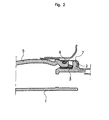
- Figures 1 to 2 illustrate a particular embodiment of the invention.
- Figure 1 shows the bowl/guide unit (4), produced in one piece, in which the guide (1) guides the nozzle into the pipe head.
- a metal ring (3) is crimped to the periphery of the unit (4).
- Teeth (2) are located around the periphery of the unit (4).
- Figure 2 shows the system mounted on the pipe head (5).
- An O-ring (6) is compressed between the periphery of the pipe head (5) and the metal head (7) inside which the unit (4) is crimped, the teeth (2) being in contact with the inside of the metal head (7).
Landscapes
- Engineering & Computer Science (AREA)
- Mechanical Engineering (AREA)
- General Engineering & Computer Science (AREA)
- Chemical & Material Sciences (AREA)
- Sustainable Development (AREA)
- Sustainable Energy (AREA)
- Life Sciences & Earth Sciences (AREA)
- Combustion & Propulsion (AREA)
- Transportation (AREA)
- Cooling, Air Intake And Gas Exhaust, And Fuel Tank Arrangements In Propulsion Units (AREA)
- Infusion, Injection, And Reservoir Apparatuses (AREA)
- Loading And Unloading Of Fuel Tanks Or Ships (AREA)
- Basic Packing Technique (AREA)
Abstract
Description
- The present invention relates to a conducting system for a filling pipe.
- Motor vehicle fuel systems usually comprise a fuel tank and a filling pipe. The filling pipe enables the fuel tank to be filled from a fuel nozzle which the user inserts into the entrance orifice of the filling pipe (the filling head, as it is also called).
- Such a conducting system is known from the document
US 6 056 029 . - In the case of tanks having a plastic pipe, it is known practice to make the plastic at least partly conducting and/or to remove electrostatic charges to the vehicle chassis in order to prevent electrostatic charges building up on its surface, with all the associated risks. For this purpose there is usually at least one metal part in contact (direct or indirect) with the plastic on the one hand, and with the vehicle chassis on the other hand.
- In this way, a plastic pipe head is usually provided with a system comprising a metal bowl force-fitted into the filling pipe and a metal head fitted onto the pipe head whose function is to establish a contact with the vehicle chassis. The system also includes a guide for the filling nozzle; this guide is usually made in one piece which is inserted into the filling bowl, its inner profile assisting in positioning the nozzle during the filling operation. This part may be made of plastic or metal.
- Where the pipe head is provided with the said system, the metal bowl is usually positioned by means of orientating features on the pipe head.
- In certain prior-art designs, the bowl comprises teeth that make axial contact with the metal head when the latter is crimped around the outside of the pipe head. An O-ring is placed between the metal head and the plastic filling pipe to provide a peripheral seal between the filling pipe and the metal head.
- A conducting path for static electricity generated during the filling operation is thus established between the nozzle, the nozzle guide, the filling bowl, the teeth of the bowl, the metal head and, via a metal lug fixed to the metal head, the vehicle chassis.
- One problem with this system is that if there are moulding defects in the pipe, at least one of the teeth of the bowl may not be in contact with the metal head once the bowl is fitted. Static electricity that may build up on the surface of the filling bowl will not then be carried away efficiently into the vehicle chassis because the conducting path is no longer continuous. Another problem with this design is that the bowl is metallic (whereas plastics are lighter and easier to form into complex shapes).
- To alleviate these problems and to simplify the fitting of the bowl to the pipe head, the subject of the invention is a conducting system for a fuel tank filling pipe, comprising
- a filling bowl made of a conducting plastic, with deformable teeth;
- a filling nozzle guide, also made of a conducting plastic, and in direct contact with the filling bowl;
- a metal head;
- According to the invention, the bowl and the nozzle guide (the function of which was described above) are inserted into the metal head; that is to say, they are in fact crimped into the said head with the aid of the teeth, or, in other words, the metal head is engaged on these parts.
- According to the invention, therefore, the bowl is provided around its periphery with deformable teeth which, when the bowl and the guide are inserted into the metal head, deform to give permanent radial contact with the metal head, even if there are moulding defects in for example the pipe head. Any static electricity generated by fuel being poured in through the filling nozzle can thus be carried away into the bodywork of the vehicle via the filling bowl, the teeth, and the metal head, this last being connected directly to the chassis of the vehicle.
- According to the invention, the guide is in direct contact with the bowl - that is, it is either mounted in or on the bowl, or made in one piece with the bowl. In the system according to the invention, the filling bowl and the guide for the filling nozzle preferably form a one-piece unit.
- The term "plastic" is used to denote any material comprising at least one synthetic resin polymer.
- All types of plastic may be suitable. Very suitable plastics belong to the category of thermoplastics.
- The term "thermoplastic" denotes any thermoplastic polymer, including thermoplastic elastomers, and their blends. The term "polymer" denotes both homopolymers and copolymers (especially binary or ternary copolymers). Without implying any limitation, examples of such copolymers are: random copolymers, linear block copolymers, other block copolymers and graft copolymers.
- Any type of thermoplastic polymer or copolymer whose melting point is below the decomposition temperature is suitable. Synthetic thermoplastics that have a melting range spread over at least 10 degrees Celsius are particularly suitable. Examples of such materials include those that exhibit polydispersion in their molecular weight.
- In particular, polyolefins, thermoplastic polyesters, polyketones, polyamides and copolymers thereof may be used. A blend of polymers or copolymers may also be used, as may a blend of polymeric materials with inorganic, organic and/or natural fillers such as the following non-exhaustive list: carbon, salts and other inorganic derivatives, and natural or polymeric fibres. It is also possible to use multilayer structures consisting of stacked layers bonded together, comprising at least one of the polymers or copolymers described above.
- More preferably, the plastic of the bowl/guide unit is conducting high-density polyethylene (HDPE) (that is to say, it comprises a conducting filler - such as carbon black or carbon fibres - and/or a conducting coating). This part or these parts (depending on whether or not they are formed in one piece) are preferably produced by injection moulding (which makes it possible to overmould them onto one or more inserts, such as a reinforcing ring for example: see later).
- According to the invention, the bowl/guide unit is force-fitted into the filling pipe. Movement of the unit relative to the pipe (axially and in rotation) is preferably prevented by an appropriate design. For example, it is advantageous to provide depressions or recesses (stamped portions) in the pipe to correspond to the teeth, in such a way that it can support axially and prevent rotation of the bowl/guide unit in the pipe because of the teeth and stamped portions acting together. In this variant, the teeth therefore have a dual function of conductivity (removal of charges) and attachment.
- The teeth are preferably flat (meaning that they are thin and of elongate shape as illustrated in the figures attached to this application). These teeth preferably give the bowl/guide unit a diameter greater than that of the opening in the metal head designed to house it. What this means is that their size is such that they are compressed by the head during assembly, thus ensuring permanence of the contact whatever the quality of the moulding of the parts (distortion, tolerances, etc.). It is advantageous to provide the system according to the invention with a seal (such as an O-ring) to seal the assembly. This seal is preferably situated on the filling pipe in a position such that it is compressed by the metal head once the system is assembled. A groove may be provided on the pipe to house and locate the seal.
- In a preferred variant of the invention, a metal annulus is present on the periphery of the bowl/guide unit, so that when the unit is installed, the annulus gives sufficient rigid support to prevent the filling pipe from deforming with the effect of age, and, by the same token, to prevent the seal deteriorating. This annulus can be crimped onto the bowl, but the bowl is preferably overmoulded onto it (to eliminate an assembly step). Most particular preference is given to overmoulding a bowl/guide unit onto it in one piece. The present invention also relates to a process for producing (assembling) a conducting system as described above. This process comprises the following steps :
- the filling pipe is provided with a seal;
- a bowl/guide unit consisting of one part, or of two parts assembled together, and provided with deformable radial teeth is force-fitted into it; and the whole is force-fitted into a metal head, simultaneously compressing both the seal and the teeth.
- Without limiting the scope of the invention,
Figures 1 to 2 illustrate a particular embodiment of the invention. -
Figure 1 shows the bowl/guide unit (4), produced in one piece, in which the guide (1) guides the nozzle into the pipe head. A metal ring (3) is crimped to the periphery of the unit (4). Teeth (2) are located around the periphery of the unit (4). -
Figure 2 shows the system mounted on the pipe head (5). An O-ring (6) is compressed between the periphery of the pipe head (5) and the metal head (7) inside which the unit (4) is crimped, the teeth (2) being in contact with the inside of the metal head (7).
Claims (10)
- Conducting system for a fuel tank filling pipe (5), comprising- a filling bowl made of a conducting plastic, with deformable teeth (2);- a filling nozzle guide, also made of a conducting plastic, and in direct contact with the filling bowl;- a metal head (7);whereby the bowl and the guide are inserted into the metal head (7) in such a way that the teeth (2) are in permanent radial contact with the metal head (7) when the bowl and the guide (4) are mounted in the filling pipe (5).
- System according to claim 1, characterized in that the filling bowl and the guide form a one-piece unit (4).
- System according to the preceding claim, characterized in that the material of the unit (4) is conducting high-density polyethylene (HDPE).
- System according to any one of the claims 2 or 3, characterized in that the unit (4) is produced using the injection-moulding technique.
- System according to any one of the preceding claims, characterized in that the bowl/guide unit (4) includes a metal ring (3) on its periphery.
- System according to the preceding claim, in which the bowl or the unit (4) is overmoulded onto the metal ring (3).
- System according to any one of the preceding claims, characterized in that the filling pipe (5) comprises stamped portions corresponding to the teeth (2) and capable of supporting axially and preventing rotation of the bowl/guide unit (4) in the pipe (5).
- System according to any one of the preceding claims, characterized in that the teeth (2) give the bowl/guide unit (4) a diameter greater than that of the opening in the metal head (7) designed to house it.
- System according to any one of the preceding claims, characterized in that a seal (6) is situated on the filling pipe (5) in a position such that it is compressed by the metal head (7) once the system is assembled.
- Process for producing a conducting system according to any one of the preceding claims and comprising the following steps:- the filling pipe (5) is provided with a seal (6);- a bowl/guide unit (4) consisting of one part, or of two parts assembled together, and provided with deformable radial teeth (2) is force-fitted into it; and- the whole is force-fitted into a metal head (7), simultaneously compressing both the seal (6) and the teeth (2).
Applications Claiming Priority (2)
| Application Number | Priority Date | Filing Date | Title |
|---|---|---|---|
| FR0502741A FR2883228B1 (en) | 2005-03-18 | 2005-03-18 | CONDUCTIVE DEVICE FOR FILLING TUBING |
| PCT/EP2006/060805 WO2006097515A1 (en) | 2005-03-18 | 2006-03-16 | Conducting system for a filling pipe |
Publications (2)
| Publication Number | Publication Date |
|---|---|
| EP1863666A1 EP1863666A1 (en) | 2007-12-12 |
| EP1863666B1 true EP1863666B1 (en) | 2011-05-25 |
Family
ID=35311528
Family Applications (1)
| Application Number | Title | Priority Date | Filing Date |
|---|---|---|---|
| EP06725111A Expired - Lifetime EP1863666B1 (en) | 2005-03-18 | 2006-03-16 | Conducting system for a filling pipe |
Country Status (9)
| Country | Link |
|---|---|
| US (1) | US20080164255A1 (en) |
| EP (1) | EP1863666B1 (en) |
| JP (1) | JP2008535715A (en) |
| KR (1) | KR101287352B1 (en) |
| CN (1) | CN101142104B (en) |
| AT (1) | ATE510720T1 (en) |
| BR (1) | BRPI0608548A2 (en) |
| FR (1) | FR2883228B1 (en) |
| WO (1) | WO2006097515A1 (en) |
Families Citing this family (5)
| Publication number | Priority date | Publication date | Assignee | Title |
|---|---|---|---|---|
| DE102010045475B3 (en) | 2010-09-16 | 2012-01-19 | Kautex Textron Gmbh & Co. Kg | Filler neck for a fuel tank of a motor vehicle |
| EP2799273B1 (en) | 2013-05-02 | 2015-07-01 | MAGNA STEYR Fuel Systems GesmbH | Tank system |
| JP6283912B2 (en) * | 2014-03-25 | 2018-02-28 | 三桜工業株式会社 | Grounding structure of fuel supply system |
| EP3112198B1 (en) | 2015-07-01 | 2017-09-13 | Magna Steyr Fuel Systems GesmbH | Fuel filling lid for a motor vehicle with improved sealing |
| US12115923B2 (en) | 2021-02-24 | 2024-10-15 | Yachiyo Industry Co., Ltd. | Earth structure for filler pipe |
Family Cites Families (19)
| Publication number | Priority date | Publication date | Assignee | Title |
|---|---|---|---|---|
| US4730652A (en) * | 1984-11-06 | 1988-03-15 | Proprietary Technology, Inc. | Automotive fuel filler system |
| DE8522203U1 (en) * | 1985-08-01 | 1985-09-19 | Rhein-Conti Kunststoff-Technik Gmbh, 6900 Heidelberg | Filler neck |
| US5111858A (en) * | 1990-12-24 | 1992-05-12 | Ford Motor Company | Interengageable plastic fuel flange and plastic filler tube |
| US5431199A (en) * | 1993-11-30 | 1995-07-11 | Benjey, Robert P | Redundant seal for vehicle filler neck |
| CN2238758Y (en) * | 1995-07-13 | 1996-10-30 | 三龙产业股份有限公司 | Fuel tank cap |
| AT403140B (en) * | 1995-08-01 | 1997-11-25 | Blau Automobiltechnik Gmbh | END PIECE FOR THE FUEL FITTING OF A VEHICLE FUEL TANK |
| FR2759032B1 (en) * | 1997-02-05 | 1999-04-23 | Journee Paul Sa | DEVICE FOR FILLING A FUEL TANK FOR A MOTOR VEHICLE COMPRISING IMPROVED ELECTRICAL GROUNDING MEANS |
| FR2759035B1 (en) * | 1997-02-05 | 1999-04-23 | Journee Paul Sa | DEVICE FOR FILLING A MOTOR VEHICLE FUEL TANK COMPRISING A FLEXIBLE GROUNDING CONTACT |
| CA2280160A1 (en) * | 1997-02-11 | 1998-08-13 | Stant Manufacturing Inc. | Seal for filler neck closure assembly |
| DE60009585T2 (en) * | 1999-01-28 | 2005-04-21 | Toyoda Gosei Kk | Fuel tank and filler neck |
| US6056029A (en) * | 1999-03-03 | 2000-05-02 | Stant Manufacturing Inc. | Fuel-Transfer system |
| US6508374B1 (en) * | 1999-11-04 | 2003-01-21 | Stant Manufacturing Inc. | Filler neck closure with static charge dissipater |
| EP1312848B1 (en) | 2001-11-20 | 2009-01-07 | Siemens Aktiengesellschaft | Pipe coupling and method to achieve a pipe coupling |
| AU2002357260A1 (en) * | 2001-12-12 | 2003-07-09 | Pilot Industries, Inc. | Spud assembly for a fuel tank |
| US7163117B2 (en) * | 2002-05-01 | 2007-01-16 | Stant Manufacturing Inc. | Static charge dissipater for filler neck closure |
| WO2003104013A1 (en) * | 2002-06-05 | 2003-12-18 | Kautex Textron Gmbh & Co. Kg | Filler tube |
| FR2844487B1 (en) * | 2002-09-13 | 2005-05-13 | Inergy Automotive Systems Res | SAFETY SYSTEM FOR LIQUID FUEL TANK |
| US7198078B2 (en) * | 2003-07-04 | 2007-04-03 | Toyoda Gosei Co., Ltd. | Filler pipe |
| US7549443B2 (en) * | 2003-12-09 | 2009-06-23 | Illinois Tool Works Inc. | Fuel shut-off valve assembly with associated components and methods of making and assembling the same |
-
2005
- 2005-03-18 FR FR0502741A patent/FR2883228B1/en not_active Expired - Fee Related
-
2006
- 2006-03-16 EP EP06725111A patent/EP1863666B1/en not_active Expired - Lifetime
- 2006-03-16 AT AT06725111T patent/ATE510720T1/en not_active IP Right Cessation
- 2006-03-16 WO PCT/EP2006/060805 patent/WO2006097515A1/en not_active Ceased
- 2006-03-16 US US11/908,908 patent/US20080164255A1/en not_active Abandoned
- 2006-03-16 JP JP2008501322A patent/JP2008535715A/en active Pending
- 2006-03-16 CN CN2006800086078A patent/CN101142104B/en not_active Expired - Lifetime
- 2006-03-16 KR KR1020077021458A patent/KR101287352B1/en not_active Expired - Lifetime
- 2006-03-16 BR BRPI0608548-2A patent/BRPI0608548A2/en not_active IP Right Cessation
Also Published As
| Publication number | Publication date |
|---|---|
| FR2883228B1 (en) | 2007-06-01 |
| ATE510720T1 (en) | 2011-06-15 |
| CN101142104A (en) | 2008-03-12 |
| EP1863666A1 (en) | 2007-12-12 |
| CN101142104B (en) | 2010-08-11 |
| KR101287352B1 (en) | 2013-07-23 |
| US20080164255A1 (en) | 2008-07-10 |
| BRPI0608548A2 (en) | 2010-11-16 |
| KR20070110523A (en) | 2007-11-19 |
| FR2883228A1 (en) | 2006-09-22 |
| WO2006097515A1 (en) | 2006-09-21 |
| JP2008535715A (en) | 2008-09-04 |
Similar Documents
| Publication | Publication Date | Title |
|---|---|---|
| CN102131667B (en) | Plastic fuel tank comprising noise reduction baffle and process for manufacturing it | |
| US6508275B1 (en) | Flexible fuel filler pipe | |
| EP1814755B1 (en) | Plastic adapter for fuel tank | |
| US20050257852A1 (en) | Closure system for a fuel tank filler pipe and method for opening this pipe | |
| US8631556B2 (en) | Process for manufacturing a plastic fuel tank equipped with a pump | |
| CN102712252A (en) | Capless refueling system | |
| US20090019683A1 (en) | Method for fastening an accessory to a plastic fuel tank | |
| US6475625B2 (en) | Plastic parts joining structure | |
| US20080164255A1 (en) | Conducting System For a Filling Pipe | |
| US20070181582A1 (en) | System for fastening two components, method of fastening by means of this fastening system, and fuel system | |
| US20110056966A1 (en) | Fuel Tank Attachment And Method For Producing A Fuel Tank Attachment | |
| EP2003007B1 (en) | Connector for fuel tank | |
| WO2007042536A1 (en) | Fuel tank filler pipe | |
| JP7187708B2 (en) | Funnel-shaped insert for fuel tank filler pipe | |
| US6497243B1 (en) | Assembly of fuel system components on a fuel tank | |
| US20090151145A1 (en) | Process for moulding a portion of a hollow component and method of fastening it to a fuel tank |
Legal Events
| Date | Code | Title | Description |
|---|---|---|---|
| PUAI | Public reference made under article 153(3) epc to a published international application that has entered the european phase |
Free format text: ORIGINAL CODE: 0009012 |
|
| 17P | Request for examination filed |
Effective date: 20071018 |
|
| AK | Designated contracting states |
Kind code of ref document: A1 Designated state(s): AT BE BG CH CY CZ DE DK EE ES FI FR GB GR HU IE IS IT LI LT LU LV MC NL PL PT RO SE SI SK TR |
|
| 17Q | First examination report despatched |
Effective date: 20080219 |
|
| RIN1 | Information on inventor provided before grant (corrected) |
Inventor name: DUFAYS, EMMANUEL Inventor name: PAOLINI, GWEREG Inventor name: COULON, PHILIPPE |
|
| DAX | Request for extension of the european patent (deleted) | ||
| GRAP | Despatch of communication of intention to grant a patent |
Free format text: ORIGINAL CODE: EPIDOSNIGR1 |
|
| GRAS | Grant fee paid |
Free format text: ORIGINAL CODE: EPIDOSNIGR3 |
|
| RIN1 | Information on inventor provided before grant (corrected) |
Inventor name: PAOLINI, GWEREG Inventor name: DUFAYS, EMMANUEL Inventor name: COULON, PHILIPPE |
|
| GRAA | (expected) grant |
Free format text: ORIGINAL CODE: 0009210 |
|
| AK | Designated contracting states |
Kind code of ref document: B1 Designated state(s): AT BE BG CH CY CZ DE DK EE ES FI FR GB GR HU IE IS IT LI LT LU LV MC NL PL PT RO SE SI SK TR |
|
| REG | Reference to a national code |
Ref country code: GB Ref legal event code: FG4D |
|
| REG | Reference to a national code |
Ref country code: CH Ref legal event code: EP |
|
| REG | Reference to a national code |
Ref country code: IE Ref legal event code: FG4D |
|
| REG | Reference to a national code |
Ref country code: DE Ref legal event code: R096 Ref document number: 602006022167 Country of ref document: DE Effective date: 20110707 |
|
| REG | Reference to a national code |
Ref country code: NL Ref legal event code: VDEP Effective date: 20110525 |
|
| PG25 | Lapsed in a contracting state [announced via postgrant information from national office to epo] |
Ref country code: SE Free format text: LAPSE BECAUSE OF FAILURE TO SUBMIT A TRANSLATION OF THE DESCRIPTION OR TO PAY THE FEE WITHIN THE PRESCRIBED TIME-LIMIT Effective date: 20110525 Ref country code: LT Free format text: LAPSE BECAUSE OF FAILURE TO SUBMIT A TRANSLATION OF THE DESCRIPTION OR TO PAY THE FEE WITHIN THE PRESCRIBED TIME-LIMIT Effective date: 20110525 Ref country code: PT Free format text: LAPSE BECAUSE OF FAILURE TO SUBMIT A TRANSLATION OF THE DESCRIPTION OR TO PAY THE FEE WITHIN THE PRESCRIBED TIME-LIMIT Effective date: 20110926 |
|
| PG25 | Lapsed in a contracting state [announced via postgrant information from national office to epo] |
Ref country code: LV Free format text: LAPSE BECAUSE OF FAILURE TO SUBMIT A TRANSLATION OF THE DESCRIPTION OR TO PAY THE FEE WITHIN THE PRESCRIBED TIME-LIMIT Effective date: 20110525 Ref country code: IS Free format text: LAPSE BECAUSE OF FAILURE TO SUBMIT A TRANSLATION OF THE DESCRIPTION OR TO PAY THE FEE WITHIN THE PRESCRIBED TIME-LIMIT Effective date: 20110925 Ref country code: FI Free format text: LAPSE BECAUSE OF FAILURE TO SUBMIT A TRANSLATION OF THE DESCRIPTION OR TO PAY THE FEE WITHIN THE PRESCRIBED TIME-LIMIT Effective date: 20110525 Ref country code: ES Free format text: LAPSE BECAUSE OF FAILURE TO SUBMIT A TRANSLATION OF THE DESCRIPTION OR TO PAY THE FEE WITHIN THE PRESCRIBED TIME-LIMIT Effective date: 20110905 Ref country code: GR Free format text: LAPSE BECAUSE OF FAILURE TO SUBMIT A TRANSLATION OF THE DESCRIPTION OR TO PAY THE FEE WITHIN THE PRESCRIBED TIME-LIMIT Effective date: 20110826 Ref country code: SI Free format text: LAPSE BECAUSE OF FAILURE TO SUBMIT A TRANSLATION OF THE DESCRIPTION OR TO PAY THE FEE WITHIN THE PRESCRIBED TIME-LIMIT Effective date: 20110525 Ref country code: BE Free format text: LAPSE BECAUSE OF FAILURE TO SUBMIT A TRANSLATION OF THE DESCRIPTION OR TO PAY THE FEE WITHIN THE PRESCRIBED TIME-LIMIT Effective date: 20110525 Ref country code: CY Free format text: LAPSE BECAUSE OF FAILURE TO SUBMIT A TRANSLATION OF THE DESCRIPTION OR TO PAY THE FEE WITHIN THE PRESCRIBED TIME-LIMIT Effective date: 20110525 Ref country code: AT Free format text: LAPSE BECAUSE OF FAILURE TO SUBMIT A TRANSLATION OF THE DESCRIPTION OR TO PAY THE FEE WITHIN THE PRESCRIBED TIME-LIMIT Effective date: 20110525 |
|
| PG25 | Lapsed in a contracting state [announced via postgrant information from national office to epo] |
Ref country code: NL Free format text: LAPSE BECAUSE OF FAILURE TO SUBMIT A TRANSLATION OF THE DESCRIPTION OR TO PAY THE FEE WITHIN THE PRESCRIBED TIME-LIMIT Effective date: 20110525 |
|
| PG25 | Lapsed in a contracting state [announced via postgrant information from national office to epo] |
Ref country code: EE Free format text: LAPSE BECAUSE OF FAILURE TO SUBMIT A TRANSLATION OF THE DESCRIPTION OR TO PAY THE FEE WITHIN THE PRESCRIBED TIME-LIMIT Effective date: 20110525 Ref country code: CZ Free format text: LAPSE BECAUSE OF FAILURE TO SUBMIT A TRANSLATION OF THE DESCRIPTION OR TO PAY THE FEE WITHIN THE PRESCRIBED TIME-LIMIT Effective date: 20110525 |
|
| PG25 | Lapsed in a contracting state [announced via postgrant information from national office to epo] |
Ref country code: RO Free format text: LAPSE BECAUSE OF FAILURE TO SUBMIT A TRANSLATION OF THE DESCRIPTION OR TO PAY THE FEE WITHIN THE PRESCRIBED TIME-LIMIT Effective date: 20110525 Ref country code: SK Free format text: LAPSE BECAUSE OF FAILURE TO SUBMIT A TRANSLATION OF THE DESCRIPTION OR TO PAY THE FEE WITHIN THE PRESCRIBED TIME-LIMIT Effective date: 20110525 Ref country code: DK Free format text: LAPSE BECAUSE OF FAILURE TO SUBMIT A TRANSLATION OF THE DESCRIPTION OR TO PAY THE FEE WITHIN THE PRESCRIBED TIME-LIMIT Effective date: 20110525 Ref country code: PL Free format text: LAPSE BECAUSE OF FAILURE TO SUBMIT A TRANSLATION OF THE DESCRIPTION OR TO PAY THE FEE WITHIN THE PRESCRIBED TIME-LIMIT Effective date: 20110525 |
|
| PLBE | No opposition filed within time limit |
Free format text: ORIGINAL CODE: 0009261 |
|
| STAA | Information on the status of an ep patent application or granted ep patent |
Free format text: STATUS: NO OPPOSITION FILED WITHIN TIME LIMIT |
|
| 26N | No opposition filed |
Effective date: 20120228 |
|
| PG25 | Lapsed in a contracting state [announced via postgrant information from national office to epo] |
Ref country code: IT Free format text: LAPSE BECAUSE OF FAILURE TO SUBMIT A TRANSLATION OF THE DESCRIPTION OR TO PAY THE FEE WITHIN THE PRESCRIBED TIME-LIMIT Effective date: 20110525 |
|
| REG | Reference to a national code |
Ref country code: DE Ref legal event code: R097 Ref document number: 602006022167 Country of ref document: DE Effective date: 20120228 |
|
| PG25 | Lapsed in a contracting state [announced via postgrant information from national office to epo] |
Ref country code: MC Free format text: LAPSE BECAUSE OF NON-PAYMENT OF DUE FEES Effective date: 20120331 |
|
| REG | Reference to a national code |
Ref country code: CH Ref legal event code: PL |
|
| GBPC | Gb: european patent ceased through non-payment of renewal fee |
Effective date: 20120316 |
|
| REG | Reference to a national code |
Ref country code: IE Ref legal event code: MM4A |
|
| PG25 | Lapsed in a contracting state [announced via postgrant information from national office to epo] |
Ref country code: GB Free format text: LAPSE BECAUSE OF NON-PAYMENT OF DUE FEES Effective date: 20120316 Ref country code: IE Free format text: LAPSE BECAUSE OF NON-PAYMENT OF DUE FEES Effective date: 20120316 Ref country code: LI Free format text: LAPSE BECAUSE OF NON-PAYMENT OF DUE FEES Effective date: 20120331 Ref country code: CH Free format text: LAPSE BECAUSE OF NON-PAYMENT OF DUE FEES Effective date: 20120331 |
|
| PG25 | Lapsed in a contracting state [announced via postgrant information from national office to epo] |
Ref country code: BG Free format text: LAPSE BECAUSE OF FAILURE TO SUBMIT A TRANSLATION OF THE DESCRIPTION OR TO PAY THE FEE WITHIN THE PRESCRIBED TIME-LIMIT Effective date: 20110825 |
|
| PG25 | Lapsed in a contracting state [announced via postgrant information from national office to epo] |
Ref country code: TR Free format text: LAPSE BECAUSE OF FAILURE TO SUBMIT A TRANSLATION OF THE DESCRIPTION OR TO PAY THE FEE WITHIN THE PRESCRIBED TIME-LIMIT Effective date: 20110525 |
|
| PG25 | Lapsed in a contracting state [announced via postgrant information from national office to epo] |
Ref country code: LU Free format text: LAPSE BECAUSE OF NON-PAYMENT OF DUE FEES Effective date: 20120316 |
|
| PG25 | Lapsed in a contracting state [announced via postgrant information from national office to epo] |
Ref country code: HU Free format text: LAPSE BECAUSE OF FAILURE TO SUBMIT A TRANSLATION OF THE DESCRIPTION OR TO PAY THE FEE WITHIN THE PRESCRIBED TIME-LIMIT Effective date: 20060316 |
|
| REG | Reference to a national code |
Ref country code: FR Ref legal event code: PLFP Year of fee payment: 10 |
|
| PGFP | Annual fee paid to national office [announced via postgrant information from national office to epo] |
Ref country code: FR Payment date: 20150326 Year of fee payment: 10 |
|
| REG | Reference to a national code |
Ref country code: FR Ref legal event code: ST Effective date: 20161130 |
|
| PG25 | Lapsed in a contracting state [announced via postgrant information from national office to epo] |
Ref country code: FR Free format text: LAPSE BECAUSE OF NON-PAYMENT OF DUE FEES Effective date: 20160331 |
|
| P01 | Opt-out of the competence of the unified patent court (upc) registered |
Effective date: 20230515 |
|
| PGFP | Annual fee paid to national office [announced via postgrant information from national office to epo] |
Ref country code: DE Payment date: 20250319 Year of fee payment: 20 |
|
| REG | Reference to a national code |
Ref country code: DE Ref legal event code: R081 Ref document number: 602006022167 Country of ref document: DE Owner name: OPMOBILITY C-POWER BELGIUM RESEARCH, BE Free format text: FORMER OWNER: INERGY AUTOMOTIVE SYSTEMS RESEARCH (SA), BRUXELLES, BE |
|
| REG | Reference to a national code |
Ref country code: DE Ref legal event code: R071 Ref document number: 602006022167 Country of ref document: DE |