EP1863592B1 - Powder paint reclaim transport system - Google Patents
Powder paint reclaim transport system Download PDFInfo
- Publication number
- EP1863592B1 EP1863592B1 EP06739978A EP06739978A EP1863592B1 EP 1863592 B1 EP1863592 B1 EP 1863592B1 EP 06739978 A EP06739978 A EP 06739978A EP 06739978 A EP06739978 A EP 06739978A EP 1863592 B1 EP1863592 B1 EP 1863592B1
- Authority
- EP
- European Patent Office
- Prior art keywords
- transporter
- powder paint
- collector
- set forth
- collectors
- Prior art date
- Legal status (The legal status is an assumption and is not a legal conclusion. Google has not performed a legal analysis and makes no representation as to the accuracy of the status listed.)
- Expired - Lifetime
Links
Images



Classifications
-
- B—PERFORMING OPERATIONS; TRANSPORTING
- B05—SPRAYING OR ATOMISING IN GENERAL; APPLYING FLUENT MATERIALS TO SURFACES, IN GENERAL
- B05B—SPRAYING APPARATUS; ATOMISING APPARATUS; NOZZLES
- B05B7/00—Spraying apparatus for discharge of liquids or other fluent materials from two or more sources, e.g. of liquid and air, of powder and gas
- B05B7/14—Spraying apparatus for discharge of liquids or other fluent materials from two or more sources, e.g. of liquid and air, of powder and gas designed for spraying particulate materials
- B05B7/1404—Arrangements for supplying particulate material
-
- B—PERFORMING OPERATIONS; TRANSPORTING
- B05—SPRAYING OR ATOMISING IN GENERAL; APPLYING FLUENT MATERIALS TO SURFACES, IN GENERAL
- B05B—SPRAYING APPARATUS; ATOMISING APPARATUS; NOZZLES
- B05B14/00—Arrangements for collecting, re-using or eliminating excess spraying material
- B05B14/40—Arrangements for collecting, re-using or eliminating excess spraying material for use in spray booths
- B05B14/48—Arrangements for collecting, re-using or eliminating excess spraying material for use in spray booths specially adapted for particulate material
Definitions
- the present application covers a powder paint reclaim system and method for reclaiming powder paint not adhered to an article being painted in a powder paint booth. More specifically, the present application relates to a powder paint reclaim system and method for reclaiming powder paint not adhered to an article being painted using positive gas pressure and gravitational forces to transport the powder paint.
- Document DE 41 34 701 A1 discloses a filter unit or a cyclone unit which can alternately be attached to a cabin to draw powder out of the cabin.
- the units move on wheels. In an operating position adjacent to the cabin, they are automatically aligned with flow connections and can be connected.
- a common fan for both units is connected with a filter unit via a compressed air cleaning device in terms of flow, if the former is in the operating position, and at the same time it closes off the inlet to a post-filter unit, while when the filter unit is removed and the cyclone unit is in the operating position, this cyclone unit is connected with the fan via the post-filter, and the cyclone unit closes off a flow inlet of the compressed air cleaning unit.
- Document WO 81/02117 A1 discloses a gas recollection unit.
- the gas recollection unit provided with an aspiration device is fixed for instance at the upper part of a movable powdering cabin and holds a powder reception unit, composed of a filtering unit and a preparation unit fixed thereto.
- the coating powder is projected on the tool by means of an electrostatic spring pistol through an opening.
- an air stream of the same direction is created in the direction of powdering across the powdering space, which stream does not carry towards the filtering assembly the particles sticking to the tool.
- the powder From the filtering assembly, as well as from the inclined plane, the powder reaches a powder container through a sieve. With the help of a quick coupling member the powder reception unit or its units can be easily exchanged.
- Document GB 2 328 387 A discloses a powder coating apparatus.
- a paint recovering device is provided for recovering a mixture of the paints sprayed by the spray guns, but not deposit on a workpiece to be coated.
- the paint recovering device includes a collecting tank situated under the spray booth and a classifying tank situated under the collecting tank and connected to its bottom.
- a vibrating mechanism is connected to the classifying tank for vibrating it.
- the classifying tank has an upper classifying chamber defined above a first screen and communicating with a first recovering tank, a middle classifying chamber defined between the first screen and a second screen and communicating with a second recovering tank, and a lower classifying chamber defined below the second screen and communicating with a third recovering tank.
- the present invention is directed at a powder paint reclaim system and a method of reclaiming powder paint according to the independent claims.
- the powder paint reclaim system in particular includes a plurality of collectors disposed beneath a powder paint booth for collecting powder paint not adhered to the article being painted.
- Each of the plurality of collectors includes a collector fluidizer for maintaining the powder paint in a fluidized state.
- a transporter is connected to at least one of the plurality of collectors for transporting powder paint from the collectors to a powder paint reclaim hopper. At least a portion of each transporter is disposed below the collector fluidizer and has a transporter fluidizer for maintaining the powder paint received from the collector in a fluidized state.
- the transporter is connected to at least one of a plurality of collectors by a transfer line that receives powder paint from a substantially lowermost region of the collector to the transporter disposed below the collector. Because the collector maintains the powder paint in a fluidized state, the powder paint flows with the assistance of gravitational forces from each collector to the transporter through the transfer line.
- the powder paint reclaim system described above solves the problems associated with known systems through the simplicity of using gravitational forces to transfer powder paint from the powder paint collectors to the transporter. Furthermore, a need for a transfer pump is eliminated by the use of air pressure that increases in the transporter through the introduction of fluidizing air through the transporter fluidizer. Therefore, powder paint is transferred from the transporter to the reclaim hoppers by positive pressure not requiring the use of vacuum pumps that are expensive and difficult to maintain.
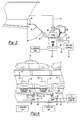
- Figure 1 is a side elevational view of the assembly showing a plurality of powder paint collectors disposed below a powder paint application booth;
- Figure 2 is a side fragmented view of a lowermost region of a powder paint collector having a exit port for transferring powder paint to a transporter;
- Figure 3 shows a partial schematic view of one embodiment of the inventive transporter connected to a powder paint collector
- Figure 4 shows a side-elevational view of a plurality of transporters in a powder paint application system
- Figure 5 shows an alternative embodiment of a plurality of transporters in a powder paint application system.
- a powder paint application assembly is generally shown at 10.
- the assembly has been described in fuller detail in United States Patent Nos. 6,471,737 filed on December 26, 2000 and United States Patent No. 6,723,145 filed January 2, 2002 , each assigned to the present applicant.
- the assembly 10 includes an enclosed application booth (not shown) where articles to be painted, such as, for example, vehicle bodies 12 are conveyed, preferably on a conveyor system, where robotic and stationary applicators (not shown) disburse powder paint.
- a grating, or other porous floor 14 separates the booth from a continuous air chamber 16, which is disposed below the booth.
- the continuous air chamber 16 generally extends the length of the booth, and is enclosed upon a bottom end by a plurality of powder paint collectors 18.
- Each powder paint collector 18 includes a filter assembly 20 which filters recirculation air that is transported to an air plenum through a duct 22 for reintroduction into the application booth.
- each collector 18 includes a collection chamber 24 and an air chamber 26 separated from the collection chamber 24 by a porous plate 28.
- a flow of air forces powder paint not adhered to the article 12 downwardly into the collectors 18 and, therefore, into the collection chamber 24.
- a constant flow of fluidizing air enters into the air chamber 26 through air chamber inlet 30 where air flows upwardly through the porous plate 28 into the air chamber 26 fluidizing the powder paint collecting in the collection chamber 24.
- the porous plate 28 slopes downwardly toward a powder outlet 32 so that the powder outlet 32 is located in a lowermost portion of the collector 18.
- the combination of the fluidizing air, the porous plate 28, and the air chamber 26 comprise a fluidizer 34 used to fluidize the powder paint forced into the collectors 18 from the powder paint booth. It should be understood by those of skill in the art that alternative fluidizer designs may be used to fluidize the powder paint disposed within the collection chamber 24 as long as the powder outlet 32 is located in the lowermost section of the collection chamber 24, the purpose of which will become more evident as the assembly 10 is explained further below.
- a transfer line 36 is operably connected to the powder outlet 32 at one end and to a transporter 38 at an opposite end.
- a plurality of transporters is shown in Figure 1 connected to the plurality of collectors 18. At least a portion of the transporter 38 is disposed below the level of the lowermost portion of the collector 18. More preferably, an upper end 40 of the transporter is disposed between about 76,2 and 152,4 mm (three and six inches) below the lowermost portion of the collection chamber 24 as identified by H, shown in Figure 3 .
- connection point of the transfer line 36 to the transporter 38 is below the lowermost portion of the collection chamber 24, or the powder outlet 32, so that gravitational forces allow the fluidized powder paint to flow from the collection chamber 24 to the transporter 38 as will become more evident when explained further below.
- the transfer line 36 slopes downwardly from the collector 18 to the transporter 38 at an angle of between generally 50° and 25° to vertical. More preferably, the slope of the transfer line 36 is below about 45° and still more preferably below about 30° as shown in Figure 3 by angle ⁇ . This has been shown to allow fluidized powder paint to flow from the collection chamber 24 to the transporter 38 with a minimal risk of blockage inside the transfer line 36.
- a transfer line valve 44 seals the link between the transporter 38 and the collector 18.
- the transfer line valve 44 is contemplated by the inventors to be a pinch valve. However, other equivalent sealing valves as known of those of skill in the art may be used as desired.
- the transporter 38 includes a transporter fluidizing plate 46 that separates the transporter fluidizing chamber 48 from the transporter air chamber 50 where fluidizing air is injected from a source of fluidizing air to fluidize the powder paint received from the collection chamber 24.
- a vent line 42 extends from the upper end 40 of the transporter 38 to the collection chamber 24 of the collector 18.
- a vent valve 57 is located in the vent line 42 to seal the vent line 42 preventing air from being transferred from the transporter 38 to the collection chamber 24.
- the purpose of the vent line 42 is to vent fluidizing air from the transporter fluidizing chamber 48 to the collector 18 at desired intervals as will be described further below.
- a reclaim hopper line 52 connects the transporter fluidizing chamber 48 to a reclaim hopper 54 where powder paint not adhered to the vehicle body 12 is transferred from the collector 18 via the transporter 38. Fluidized powder paint is transferred from the transporter 38 to the reclaim hopper 54 by positive pressure established inside the transporter by injecting fluidized air.
- a fill step During operation, four sequential steps take place, a fill step, a pressurized step, a pushing step, and a venting step.
- the transfer line valve 44 is open, the vent valve 57 is open, and the reclaim valve 56 is closed.
- fluidizing air is injected into the transporter air chamber 50 at a low pressure, preferably at a pressure of 68,965 kPa (10 psig) or below at a flow rate of 9,44 litre per minute to 14,16 litre per minute (20 to 30 cubic feet per hour).
- the low pressure and flow rate of fluidizing air allows the powder paint to flow downwardly through the transfer line 36 while still providing enough fluidizing air to fluidize the powder paint entering the transporter 38.
- the pressurizing step is initiated where the transfer line valve 44, the vent valve 57, and the reclaim valve 56 are all closed.
- the fluidizing air is increased to a flow rate of about 47,20 to 94,40 litre per minute (100 to 200 cubic feet per hour) to build up the pressure in the transporter to between generally 68,948 and 137,896 kPa (10 and 20 psig).
- the transfer line valve 44 is closed, the vent valve 57 is closed, and the reclaim valve 56 is opened. Because the gas pressure inside the transporter 38 has been increased to between 68,948 and 137,896 kPa (10 and 20 psig), the fluidized powder disposed within the transporter fluidizing chamber 48 is forced through the opened reclaim hopper line 52 to the reclaim hopper 54 without requiring the use of a pump.
- the venting step takes place where the transfer line valve 44 is closed, the vent valve 57 is opened, and the reclaim valve 56 is also closed.
- the fluidizing air injected into the transport air chamber 50 is terminated, and excess air from the transporter fluidizing chamber 48 is vented into the collection chamber 24 of the collector 18 substantially equalizing the gas pressure between the transporter 38 and the collector 18 enabling fluidized power to flow downwardly from the collectors 18 to the transporter 38.
- An additional step to clear the transfer line 36 of any plugs, is performed just prior to the fill step when fluidizing air is injected into the transporter 38 creating a pressure of between about 6,895 and 34,474 kPa (1 and 5 psig) for a period of one to ten seconds and the transfer line valve 44 is briefly opened allowing fluidizing air to flow backward through the transfer line 36.
- each collector 18 is connected in the manner set forth above to a transporter 38. It is contemplated by the inventors that each transporter 38 has a separate reclaim hopper line 52 for transferring the fluidized powder from the transporter 38 to the reclaim hopper 54. However, it should be understood by those of skill in the art that a common reclaim hopper line 52 to each transporter 38 may also be used.
- pairs of collectors 118 are oriented so that the lowermost portion of the collection chamber 124 is positioned in an adjacent manner so that a single transporter 138 services two collectors 118.
- the transporter 138 receives fluidized powder paint through two transfer lines 136, one each connected to the lowermost portion of the adjacent collection chambers 124.
Landscapes
- Details Or Accessories Of Spraying Plant Or Apparatus (AREA)
- Coating Apparatus (AREA)
- Application Of Or Painting With Fluid Materials (AREA)
Abstract
Description
- The present application claims priority to United States Provisional Patent Application No.
60/665,989 filed on March 29, 2005 - The present application covers a powder paint reclaim system and method for reclaiming powder paint not adhered to an article being painted in a powder paint booth. More specifically, the present application relates to a powder paint reclaim system and method for reclaiming powder paint not adhered to an article being painted using positive gas pressure and gravitational forces to transport the powder paint.
- Document
DE 41 34 701 A1 discloses a filter unit or a cyclone unit which can alternately be attached to a cabin to draw powder out of the cabin. The units move on wheels. In an operating position adjacent to the cabin, they are automatically aligned with flow connections and can be connected. A common fan for both units is connected with a filter unit via a compressed air cleaning device in terms of flow, if the former is in the operating position, and at the same time it closes off the inlet to a post-filter unit, while when the filter unit is removed and the cyclone unit is in the operating position, this cyclone unit is connected with the fan via the post-filter, and the cyclone unit closes off a flow inlet of the compressed air cleaning unit. - Document
WO 81/02117 A1 - Document
GB 2 328 387 A - To comply with ever-increasingly strict environmental regulations, the original equipment manufacturers such as, for example, automobile manufacturers, have been forced to modify the method by which articles are decorated and protected with paint. While many paint application systems have been converted from solvent-based to water-based paint, it has become apparent that powder paint application systems are preferable in many situations.
- One reason that the application of powder paint is preferable to the application of liquid-based paint is because the nearly 100% transfer efficiency achieved by the paint application process. As is known to those of skill in the art, a high percentage of paint does not adhere to the article being painted even when an electrostatic application process is used. When applying a liquid-based paint, paint not adhered to the article is blown downwardly into a sheet of water disposed below the paint application booth removing the "over-sprayed paint" from the process. The drawback of this system is that the sheet of water that collects the paint must be processed as hazardous waste and the paint must be disposed of.
- In a powder paint application system, over-sprayed paint is collected in a series of collectors disposed beneath the paint application booth where the paint is reclaimed and returned to be reapplied to subsequent articles. While this process increases transfer efficiency to near 100%, the process is known to be complex and costly to maintain due to the pumping systems required to transfer the powder from the collectors to a reclamation hopper for further use. One such prior art system is disclosed in United States Patent No.
6,679,193 to Nordson Corporation, where a number of vacuum pumps are used to draw powder from the collectors disposed beneath the powder paint application booth and subsequently pump the reclaim powder to a powder paint reclamation hopper. The use of vacuum pumps requires the use of complex valving along with a number of the expensive vacuum pumps disbursed throughout the reclamation system. - Therefore, the need exists to provide a powder paint reclaim system that is simple to use and easy to maintain to reduce the construction and operation costs of the powder paint system while maintaining a near 100% transfer efficiency.
- The present invention is directed at a powder paint reclaim system and a method of reclaiming powder paint according to the independent claims.
- The powder paint reclaim system in particular includes a plurality of collectors disposed beneath a powder paint booth for collecting powder paint not adhered to the article being painted. Each of the plurality of collectors includes a collector fluidizer for maintaining the powder paint in a fluidized state. A transporter is connected to at least one of the plurality of collectors for transporting powder paint from the collectors to a powder paint reclaim hopper. At least a portion of each transporter is disposed below the collector fluidizer and has a transporter fluidizer for maintaining the powder paint received from the collector in a fluidized state.
- The transporter is connected to at least one of a plurality of collectors by a transfer line that receives powder paint from a substantially lowermost region of the collector to the transporter disposed below the collector. Because the collector maintains the powder paint in a fluidized state, the powder paint flows with the assistance of gravitational forces from each collector to the transporter through the transfer line.
- The powder paint reclaim system described above solves the problems associated with known systems through the simplicity of using gravitational forces to transfer powder paint from the powder paint collectors to the transporter. Furthermore, a need for a transfer pump is eliminated by the use of air pressure that increases in the transporter through the introduction of fluidizing air through the transporter fluidizer. Therefore, powder paint is transferred from the transporter to the reclaim hoppers by positive pressure not requiring the use of vacuum pumps that are expensive and difficult to maintain.
- Other advantages of the present invention will be readily appreciated as the same becomes better understood by reference to the following detailed description when considered in connection with the accompanying drawings wherein:
-
Figure 1 is a side elevational view of the assembly showing a plurality of powder paint collectors disposed below a powder paint application booth; -
Figure 2 is a side fragmented view of a lowermost region of a powder paint collector having a exit port for transferring powder paint to a transporter; -
Figure 3 shows a partial schematic view of one embodiment of the inventive transporter connected to a powder paint collector; -
Figure 4 shows a side-elevational view of a plurality of transporters in a powder paint application system; and -
Figure 5 shows an alternative embodiment of a plurality of transporters in a powder paint application system. - Referring to
Figure 1 , a powder paint application assembly is generally shown at 10. The assembly has been described in fuller detail in United States Patent Nos.6,471,737 filed on December 26, 2000 and United States Patent No.6,723,145 filed January 2, 2002 , each assigned to the present applicant. Theassembly 10 includes an enclosed application booth (not shown) where articles to be painted, such as, for example,vehicle bodies 12 are conveyed, preferably on a conveyor system, where robotic and stationary applicators (not shown) disburse powder paint. A grating, or otherporous floor 14 separates the booth from acontinuous air chamber 16, which is disposed below the booth. Thecontinuous air chamber 16, generally extends the length of the booth, and is enclosed upon a bottom end by a plurality ofpowder paint collectors 18. - Each
powder paint collector 18 includes afilter assembly 20 which filters recirculation air that is transported to an air plenum through aduct 22 for reintroduction into the application booth. - As best represented in
Figure 2 , eachcollector 18 includes acollection chamber 24 and anair chamber 26 separated from thecollection chamber 24 by aporous plate 28. As stated above, a flow of air forces powder paint not adhered to thearticle 12 downwardly into thecollectors 18 and, therefore, into thecollection chamber 24. A constant flow of fluidizing air enters into theair chamber 26 throughair chamber inlet 30 where air flows upwardly through theporous plate 28 into theair chamber 26 fluidizing the powder paint collecting in thecollection chamber 24. - Preferably, the
porous plate 28 slopes downwardly toward apowder outlet 32 so that thepowder outlet 32 is located in a lowermost portion of thecollector 18. The combination of the fluidizing air, theporous plate 28, and theair chamber 26 comprise afluidizer 34 used to fluidize the powder paint forced into thecollectors 18 from the powder paint booth. It should be understood by those of skill in the art that alternative fluidizer designs may be used to fluidize the powder paint disposed within thecollection chamber 24 as long as thepowder outlet 32 is located in the lowermost section of thecollection chamber 24, the purpose of which will become more evident as theassembly 10 is explained further below. - A
transfer line 36 is operably connected to thepowder outlet 32 at one end and to atransporter 38 at an opposite end. A plurality of transporters is shown inFigure 1 connected to the plurality ofcollectors 18. At least a portion of thetransporter 38 is disposed below the level of the lowermost portion of thecollector 18. More preferably, anupper end 40 of the transporter is disposed between about 76,2 and 152,4 mm (three and six inches) below the lowermost portion of thecollection chamber 24 as identified by H, shown inFigure 3 . In any event, the connection point of thetransfer line 36 to thetransporter 38 is below the lowermost portion of thecollection chamber 24, or thepowder outlet 32, so that gravitational forces allow the fluidized powder paint to flow from thecollection chamber 24 to thetransporter 38 as will become more evident when explained further below. - The
transfer line 36 slopes downwardly from thecollector 18 to thetransporter 38 at an angle of between generally 50° and 25° to vertical. More preferably, the slope of thetransfer line 36 is below about 45° and still more preferably below about 30° as shown inFigure 3 by angle θ. This has been shown to allow fluidized powder paint to flow from thecollection chamber 24 to thetransporter 38 with a minimal risk of blockage inside thetransfer line 36. Atransfer line valve 44 seals the link between thetransporter 38 and thecollector 18. Thetransfer line valve 44 is contemplated by the inventors to be a pinch valve. However, other equivalent sealing valves as known of those of skill in the art may be used as desired. - The
transporter 38 includes atransporter fluidizing plate 46 that separates the transporter fluidizing chamber 48 from thetransporter air chamber 50 where fluidizing air is injected from a source of fluidizing air to fluidize the powder paint received from thecollection chamber 24. - A
vent line 42 extends from theupper end 40 of thetransporter 38 to thecollection chamber 24 of thecollector 18. Avent valve 57 is located in thevent line 42 to seal thevent line 42 preventing air from being transferred from thetransporter 38 to thecollection chamber 24. The purpose of thevent line 42 is to vent fluidizing air from the transporter fluidizing chamber 48 to thecollector 18 at desired intervals as will be described further below. - A reclaim
hopper line 52 , or manifold connects the transporter fluidizing chamber 48 to a reclaimhopper 54 where powder paint not adhered to thevehicle body 12 is transferred from thecollector 18 via thetransporter 38. Fluidized powder paint is transferred from thetransporter 38 to the reclaimhopper 54 by positive pressure established inside the transporter by injecting fluidized air. - During operation, four sequential steps take place, a fill step, a pressurized step, a pushing step, and a venting step. During the filling step, the
transfer line valve 44 is open, thevent valve 57 is open, and the reclaimvalve 56 is closed. Additionally, fluidizing air is injected into thetransporter air chamber 50 at a low pressure, preferably at a pressure of 68,965 kPa (10 psig) or below at a flow rate of 9,44 litre per minute to 14,16 litre per minute (20 to 30 cubic feet per hour). The low pressure and flow rate of fluidizing air allows the powder paint to flow downwardly through thetransfer line 36 while still providing enough fluidizing air to fluidize the powder paint entering thetransporter 38. - Once the
transporter 38 has been filled to a desired level with powder paint, the pressurizing step is initiated where thetransfer line valve 44, thevent valve 57, and the reclaimvalve 56 are all closed. The fluidizing air is increased to a flow rate of about 47,20 to 94,40 litre per minute (100 to 200 cubic feet per hour) to build up the pressure in the transporter to between generally 68,948 and 137,896 kPa (10 and 20 psig). - During the pushing step where the powder paint disposed in the transporter fluidizing chamber 48 is transferred to the reclaim
hopper 54, thetransfer line valve 44 is closed, thevent valve 57 is closed, and the reclaimvalve 56 is opened. Because the gas pressure inside thetransporter 38 has been increased to between 68,948 and 137,896 kPa (10 and 20 psig), the fluidized powder disposed within the transporter fluidizing chamber 48 is forced through the opened reclaimhopper line 52 to the reclaimhopper 54 without requiring the use of a pump. - Once the
transporter 38 has been sufficiently emptied of the fluidized powder, the venting step takes place where thetransfer line valve 44 is closed, thevent valve 57 is opened, and the reclaimvalve 56 is also closed. During the venting step, the fluidizing air injected into thetransport air chamber 50 is terminated, and excess air from the transporter fluidizing chamber 48 is vented into thecollection chamber 24 of thecollector 18 substantially equalizing the gas pressure between thetransporter 38 and thecollector 18 enabling fluidized power to flow downwardly from thecollectors 18 to thetransporter 38. - An additional step to clear the
transfer line 36 of any plugs, is performed just prior to the fill step when fluidizing air is injected into thetransporter 38 creating a pressure of between about 6,895 and 34,474 kPa (1 and 5 psig) for a period of one to ten seconds and thetransfer line valve 44 is briefly opened allowing fluidizing air to flow backward through thetransfer line 36. - Referring now to
Figure 4 , one preferred embodiment of theassembly 10 shows a plurality ofcollectors 18 arranged in a row below thecontinuous air chamber 16. In this embodiment, eachcollector 18 is connected in the manner set forth above to atransporter 38. It is contemplated by the inventors that eachtransporter 38 has a separate reclaimhopper line 52 for transferring the fluidized powder from thetransporter 38 to the reclaimhopper 54. However, it should be understood by those of skill in the art that a common reclaimhopper line 52 to eachtransporter 38 may also be used. - Referring now to
Figure 5 , an alternate embodiment of the inventive assembly is generally shown at 110. In this embodiment, pairs ofcollectors 118 are oriented so that the lowermost portion of thecollection chamber 124 is positioned in an adjacent manner so that asingle transporter 138 services twocollectors 118. As such, thetransporter 138 receives fluidized powder paint through twotransfer lines 136, one each connected to the lowermost portion of theadjacent collection chambers 124. In this embodiment, it is believed that only asingle vent line 142 is required for eachtransporter 138 and is linked to asingle collector 118. It should also be understood that the process set forth above by which fluidized powder paint is removed from thecollection chamber 24 and transferred to the reclaimhopper 54 by way of thetransporter 38 is the same as that used by the alternative embodiment of theassembly 110 using thealternative transporter 138 having twotransfer lines 136. - The invention has been described in an illustrative manner, and it is to be understood that the terminology which has been used is intended to be in the nature of words of description rather than of limitation.
- Obviously, many modifications and variations of the present invention are possible in light of the above teachings. It is, therefore, to be understood that within the scope of the appended claim, the invention may be practiced otherwise than as specifically described.
Claims (21)
- A powder paint reclaim system, comprising:a plurality of collectors (18) disposed beneath a paint booth for collecting powder paint not adhered to the article being painted, each of said plurality of collectors (18) having a collector fluidizer for maintaining the powder paint in a fluidized state;a transporter (38) connected to at least one of said plurality of collectors (18) for transporting powder paint from said collectors (18) to a powder paint reclaim hopper (54), each transporter (38) having at least a portion thereof disposed below said collector fluidizer and having a transporter fluidizer for maintaining the powder paint in a fluidized state; andsaid transporter (38) being connected to at least one of said plurality of collectors (18) by a transfer line (36) receiving powder paint from a substantially lowermost region of said collector (18) to a portion of said transporter (38) disposed below said collector (18) thereby enabling powder paint maintained in a fluidized state to gravitationally flow from said at least one of said plurality of collectors (18) to said transporter (38) and from said transporter (38) to said powder paint reclaim hopper (54) under positive pressure generated inside said transporter (38);wherein said transporter (38) is connected to a source of fluidizing air providing positive pressure to said transporter (38) thereby transferring fluidized powder paint to said powder paint reclaim hopper (54).
- The systems as set forth in claim 1, wherein said transfer line (36) is oriented at an angle.to vertical of less than about 45 degrees.
- The system as set forth in claim 1, wherein said transfer line (36) is oriented at an angle to vertical of less than about 30 degrees.
- The system as set forth in claim 1, wherein said transfer line (36) is connected to said transporter (38) adjacent said collector fluidizer.
- The system as set forth in claim 1, wherein said collector fluidizer includes a fluidizing plate having a porous composition and sloping downwardly toward said transfer line (36).
- The system as set forth in claim 1, wherein said transfer line (36) defines slope with to vertical and intersects said transporter (38) at an angle substantially constant with said slope.
- The system as set forth in claim 1, wherein said collector (18) includes a lower end and said transporter (38) includes an upper end terminating at a location spaced below said lower end of said collector (18).
- The system as set forth in claim 7, wherein said upper end of said transporter (38) is disposed at least about 76,2 mm (three inches) below said lower end of said collector (18).
- The system as set forth in claim 1, including a vent line selectively interconnecting said transporter (38) and said collector (18) to vent pressurized air to said collector (18).
- A method of reclaiming powder paint not adhered to an object being painted in a powder paint application booth having a collector (18) disposed below said powder paint application booth wherein the powder paint not adhered to the object being painted is collected for transfer to a powder paint reclaim hopper (54), comprising the steps of:providing a transporter (38) disposed between said collector (18) and said powder paint reclaim hopper (54) for transferring powder paint from said collector (18) to said powder paint reclaim hopper (54);equalizing the gas pressure between said collector (18) and said transporter (38);opening a powder paint link between said collector (18) and said transporter (38) thereby allowing powder paint to flow from said collector (18) to said transporter (38) with gravitational forces;closing said link between said collector (18) and said transporter (38);increasing the gas pressure inside said transporter (38) thereby creating a positive pressure inside said transporter (38) greater than atmospheric pressure; andopening a link between said transporter (38) and said powder paint reclaim hopper (54) having a gas pressure lower than said transporter (38) thereby pushing the powder paint from said transporter (38) to said powder paint reclaim hopper (54).
- The method set forth in claim 10, wherein said step of increasing the gas pressure inside said transporter (38) is further defined by sealing said transporter (38) and injecting fluidizing gas into said transporter (38).
- The method as set forth in claim 10, wherein said step of increasing the gas pressure inside said transporter (38) is further defined by increasing the gas pressure between about 68,948 kPa (10 psig) and 137,896 kPa (20 psig).
- The method as set forth in claim 10, wherein said step of opening a link between said collector (18) and said transporter (38) is further defined by opening a sealable valve disposed between said collector (18) and said transporter (38).
- The method as set forth in claim 10, further including the step of clearing said link between said transporter (38) and said collector (18) by opening said link between said transporter (38) and said collector (18) after the gas pressure of said transporter (38) has been increased.
- The method as set forth in claim 10, wherein said step of equalizing the gas pressure between said transporter (38) and said collector (18) is performed just prior to opening said link between said collector (18) and said transporter (38).
- The method as set forth in claim 10, wherein said step of equalizing the gas pressure between said transporter (38) and said collector (18) is further defined by venting air from said transporter (38) into said collector (18).
- The method as set forth in claim 10, wherein said step of increasing the gas pressure inside said transporter (38) is further defined by injecting fluidizing air into said transporter (38) at a volumetric flow rate of between about 9,44 and 14,16 litre per minute (twenty and thirty cubic feet per hour).
- The system as defined in Claim 6, wherein said system includes a control connected to discharge valves opening only one of said discharge valves at a time to deliver powder paint from one of said plurality of transporters (38) to said powder paint reclaim hopper (54) at a time through a manifold line.
- The system as defined in Claim 6, wherein said system includes a plurality of powder paint collection chambers (24) located beneath a powder paint spray booth collecting powder paint overspray from said paint booth and each of said plurality of transporters (38) is connected to a powder paint collection chamber (24) by a transfer line (36) having a transfer line valve (44).
- The system as defined in Claim 8, wherein each of said plurality of transporters (38) includes a vent line (42) having an inlet at an upper portion of said transporters (38) and an outlet connected to an upper portion of a powder paint collection chamber (24).
- The system as defined in Claim 8, wherein each of said plurality of transporters (38) is connected to a plurality of powder paint collection chambers (24) by a transfer line (36).
Applications Claiming Priority (2)
| Application Number | Priority Date | Filing Date | Title |
|---|---|---|---|
| US66598905P | 2005-03-29 | 2005-03-29 | |
| PCT/US2006/011533 WO2006105235A1 (en) | 2005-03-29 | 2006-03-29 | Powder paint reclaim transport system |
Publications (3)
| Publication Number | Publication Date |
|---|---|
| EP1863592A1 EP1863592A1 (en) | 2007-12-12 |
| EP1863592A4 EP1863592A4 (en) | 2010-04-28 |
| EP1863592B1 true EP1863592B1 (en) | 2011-10-19 |
Family
ID=37053711
Family Applications (1)
| Application Number | Title | Priority Date | Filing Date |
|---|---|---|---|
| EP06739978A Expired - Lifetime EP1863592B1 (en) | 2005-03-29 | 2006-03-29 | Powder paint reclaim transport system |
Country Status (3)
| Country | Link |
|---|---|
| EP (1) | EP1863592B1 (en) |
| AT (1) | ATE529194T1 (en) |
| WO (1) | WO2006105235A1 (en) |
Families Citing this family (2)
| Publication number | Priority date | Publication date | Assignee | Title |
|---|---|---|---|---|
| CN108654898A (en) * | 2018-06-14 | 2018-10-16 | 重庆阿罗网络科技有限公司 | The collection device of powdery paints |
| CN116493169B (en) * | 2023-05-18 | 2025-09-16 | 桂林科奥静电涂装设备有限公司 | Adjustable powder spraying recovery system |
Family Cites Families (8)
| Publication number | Priority date | Publication date | Assignee | Title |
|---|---|---|---|---|
| DE3003158A1 (en) * | 1980-01-30 | 1982-03-04 | ESB Elektrostatische Sprüh- und Beschichtungsanlagen G.F. Vöhringer GmbH, 7758 Meersburg | DEVICE FOR THE POWDER COATING OF WORKPIECES WITH A SPRAYING CABIN TEMPORARY FROM THE WORKPIECE |
| DE4134701C2 (en) * | 1991-10-21 | 1996-06-05 | Gema Volstatic Ag | Powder spray coating device with alternatively exchangeable filter and cyclone units |
| US5743958A (en) | 1993-05-25 | 1998-04-28 | Nordson Corporation | Vehicle powder coating system |
| US5766355A (en) * | 1994-09-28 | 1998-06-16 | Abb Flexible Automation Inc. | Exhaust arrangements for powder spray booth |
| JPH1157550A (en) * | 1997-08-22 | 1999-03-02 | Honda Motor Co Ltd | Powder coating method and powder coating equipment |
| US6471737B2 (en) | 2000-12-26 | 2002-10-29 | Durr Industries, Inc. | Underbooth powder paint collector |
| US20030051663A1 (en) * | 2001-09-19 | 2003-03-20 | Tomlin Edward E. | Powder collection system for a powder paint spray booth |
| US6723145B2 (en) | 2002-01-02 | 2004-04-20 | Dürr Industries, Inc. | Open powder booth collection design |
-
2006
- 2006-03-29 EP EP06739978A patent/EP1863592B1/en not_active Expired - Lifetime
- 2006-03-29 AT AT06739978T patent/ATE529194T1/en not_active IP Right Cessation
- 2006-03-29 WO PCT/US2006/011533 patent/WO2006105235A1/en not_active Ceased
Also Published As
| Publication number | Publication date |
|---|---|
| WO2006105235A1 (en) | 2006-10-05 |
| EP1863592A1 (en) | 2007-12-12 |
| ATE529194T1 (en) | 2011-11-15 |
| EP1863592A4 (en) | 2010-04-28 |
Similar Documents
| Publication | Publication Date | Title |
|---|---|---|
| EP0974400B1 (en) | Powder coating system | |
| US5153028A (en) | Method for powder coating objects and collecting oversprayed powder | |
| US7074274B1 (en) | Quick color change powder coating system | |
| JP2537938B2 (en) | Powder spraying equipment | |
| US6840463B2 (en) | Quick color change system | |
| TWI500483B (en) | Blasting chamber | |
| EP0767707B1 (en) | Powder paint booth backflow filter apparatus | |
| CN102971082A (en) | Powder supply device and method for automatically cleaning powder supply device | |
| JP2551716B2 (en) | Powder coating spray equipment | |
| EP2506983A1 (en) | Apparatus and method for recovery and dry treatment of overs pray in a painting booth | |
| US7014670B2 (en) | Controlling cyclone efficiency with a vacuum interface | |
| CA1182997A (en) | Powder spray booth | |
| WO2006105235A1 (en) | Powder paint reclaim transport system | |
| CN109718959B (en) | Powder spraying equipment suitable for high-speed spraying and efficient recovery and working method thereof | |
| CN207430586U (en) | A kind of electromobile frame intelligence spray equipment | |
| EP1332802A2 (en) | Spray painting booth | |
| CA2445482C (en) | Controlling cyclone efficiency with vacuum interface |
Legal Events
| Date | Code | Title | Description |
|---|---|---|---|
| PUAI | Public reference made under article 153(3) epc to a published international application that has entered the european phase |
Free format text: ORIGINAL CODE: 0009012 |
|
| 17P | Request for examination filed |
Effective date: 20070919 |
|
| AK | Designated contracting states |
Kind code of ref document: A1 Designated state(s): AT BE BG CH CY CZ DE DK EE ES FI FR GB GR HU IE IS IT LI LT LU LV MC NL PL PT RO SE SI SK TR |
|
| RIN1 | Information on inventor provided before grant (corrected) |
Inventor name: COLE, DAVID, J. Inventor name: KLOBUCAR, JOSEPH, M. |
|
| DAX | Request for extension of the european patent (deleted) | ||
| RAP1 | Party data changed (applicant data changed or rights of an application transferred) |
Owner name: DUERR SYSTEMS GMBH |
|
| A4 | Supplementary search report drawn up and despatched |
Effective date: 20100331 |
|
| 17Q | First examination report despatched |
Effective date: 20100920 |
|
| GRAP | Despatch of communication of intention to grant a patent |
Free format text: ORIGINAL CODE: EPIDOSNIGR1 |
|
| RIC1 | Information provided on ipc code assigned before grant |
Ipc: B05B 15/12 20060101AFI20110513BHEP Ipc: B05C 5/00 20060101ALI20110513BHEP |
|
| GRAS | Grant fee paid |
Free format text: ORIGINAL CODE: EPIDOSNIGR3 |
|
| GRAA | (expected) grant |
Free format text: ORIGINAL CODE: 0009210 |
|
| AK | Designated contracting states |
Kind code of ref document: B1 Designated state(s): AT BE BG CH CY CZ DE DK EE ES FI FR GB GR HU IE IS IT LI LT LU LV MC NL PL PT RO SE SI SK TR |
|
| REG | Reference to a national code |
Ref country code: GB Ref legal event code: FG4D |
|
| REG | Reference to a national code |
Ref country code: DE Ref legal event code: R081 Ref document number: 602006025214 Country of ref document: DE Owner name: DUERR SYSTEMS AG, DE Free format text: FORMER OWNER: DUERR SYSTEMS GMBH, 70435 STUTTGART, DE |
|
| REG | Reference to a national code |
Ref country code: CH Ref legal event code: EP |
|
| REG | Reference to a national code |
Ref country code: IE Ref legal event code: FG4D |
|
| REG | Reference to a national code |
Ref country code: DE Ref legal event code: R096 Ref document number: 602006025214 Country of ref document: DE Effective date: 20111222 |
|
| REG | Reference to a national code |
Ref country code: SE Ref legal event code: TRGR |
|
| REG | Reference to a national code |
Ref country code: NL Ref legal event code: VDEP Effective date: 20111019 |
|
| LTIE | Lt: invalidation of european patent or patent extension |
Effective date: 20111019 |
|
| REG | Reference to a national code |
Ref country code: SK Ref legal event code: T3 Ref document number: E 10992 Country of ref document: SK |
|
| REG | Reference to a national code |
Ref country code: AT Ref legal event code: MK05 Ref document number: 529194 Country of ref document: AT Kind code of ref document: T Effective date: 20111019 |
|
| PG25 | Lapsed in a contracting state [announced via postgrant information from national office to epo] |
Ref country code: BE Free format text: LAPSE BECAUSE OF FAILURE TO SUBMIT A TRANSLATION OF THE DESCRIPTION OR TO PAY THE FEE WITHIN THE PRESCRIBED TIME-LIMIT Effective date: 20111019 Ref country code: IS Free format text: LAPSE BECAUSE OF FAILURE TO SUBMIT A TRANSLATION OF THE DESCRIPTION OR TO PAY THE FEE WITHIN THE PRESCRIBED TIME-LIMIT Effective date: 20120219 Ref country code: LT Free format text: LAPSE BECAUSE OF FAILURE TO SUBMIT A TRANSLATION OF THE DESCRIPTION OR TO PAY THE FEE WITHIN THE PRESCRIBED TIME-LIMIT Effective date: 20111019 |
|
| PG25 | Lapsed in a contracting state [announced via postgrant information from national office to epo] |
Ref country code: SI Free format text: LAPSE BECAUSE OF FAILURE TO SUBMIT A TRANSLATION OF THE DESCRIPTION OR TO PAY THE FEE WITHIN THE PRESCRIBED TIME-LIMIT Effective date: 20111019 Ref country code: GR Free format text: LAPSE BECAUSE OF FAILURE TO SUBMIT A TRANSLATION OF THE DESCRIPTION OR TO PAY THE FEE WITHIN THE PRESCRIBED TIME-LIMIT Effective date: 20120120 Ref country code: LV Free format text: LAPSE BECAUSE OF FAILURE TO SUBMIT A TRANSLATION OF THE DESCRIPTION OR TO PAY THE FEE WITHIN THE PRESCRIBED TIME-LIMIT Effective date: 20111019 Ref country code: PT Free format text: LAPSE BECAUSE OF FAILURE TO SUBMIT A TRANSLATION OF THE DESCRIPTION OR TO PAY THE FEE WITHIN THE PRESCRIBED TIME-LIMIT Effective date: 20120220 Ref country code: NL Free format text: LAPSE BECAUSE OF FAILURE TO SUBMIT A TRANSLATION OF THE DESCRIPTION OR TO PAY THE FEE WITHIN THE PRESCRIBED TIME-LIMIT Effective date: 20111019 |
|
| PG25 | Lapsed in a contracting state [announced via postgrant information from national office to epo] |
Ref country code: CY Free format text: LAPSE BECAUSE OF FAILURE TO SUBMIT A TRANSLATION OF THE DESCRIPTION OR TO PAY THE FEE WITHIN THE PRESCRIBED TIME-LIMIT Effective date: 20111019 |
|
| PG25 | Lapsed in a contracting state [announced via postgrant information from national office to epo] |
Ref country code: DK Free format text: LAPSE BECAUSE OF FAILURE TO SUBMIT A TRANSLATION OF THE DESCRIPTION OR TO PAY THE FEE WITHIN THE PRESCRIBED TIME-LIMIT Effective date: 20111019 Ref country code: EE Free format text: LAPSE BECAUSE OF FAILURE TO SUBMIT A TRANSLATION OF THE DESCRIPTION OR TO PAY THE FEE WITHIN THE PRESCRIBED TIME-LIMIT Effective date: 20111019 Ref country code: BG Free format text: LAPSE BECAUSE OF FAILURE TO SUBMIT A TRANSLATION OF THE DESCRIPTION OR TO PAY THE FEE WITHIN THE PRESCRIBED TIME-LIMIT Effective date: 20120119 Ref country code: CZ Free format text: LAPSE BECAUSE OF FAILURE TO SUBMIT A TRANSLATION OF THE DESCRIPTION OR TO PAY THE FEE WITHIN THE PRESCRIBED TIME-LIMIT Effective date: 20111019 |
|
| PLBE | No opposition filed within time limit |
Free format text: ORIGINAL CODE: 0009261 |
|
| STAA | Information on the status of an ep patent application or granted ep patent |
Free format text: STATUS: NO OPPOSITION FILED WITHIN TIME LIMIT |
|
| PG25 | Lapsed in a contracting state [announced via postgrant information from national office to epo] |
Ref country code: PL Free format text: LAPSE BECAUSE OF FAILURE TO SUBMIT A TRANSLATION OF THE DESCRIPTION OR TO PAY THE FEE WITHIN THE PRESCRIBED TIME-LIMIT Effective date: 20111019 Ref country code: RO Free format text: LAPSE BECAUSE OF FAILURE TO SUBMIT A TRANSLATION OF THE DESCRIPTION OR TO PAY THE FEE WITHIN THE PRESCRIBED TIME-LIMIT Effective date: 20111019 |
|
| 26N | No opposition filed |
Effective date: 20120720 |
|
| PG25 | Lapsed in a contracting state [announced via postgrant information from national office to epo] |
Ref country code: MC Free format text: LAPSE BECAUSE OF NON-PAYMENT OF DUE FEES Effective date: 20120331 |
|
| REG | Reference to a national code |
Ref country code: CH Ref legal event code: PL |
|
| REG | Reference to a national code |
Ref country code: DE Ref legal event code: R097 Ref document number: 602006025214 Country of ref document: DE Effective date: 20120720 |
|
| GBPC | Gb: european patent ceased through non-payment of renewal fee |
Effective date: 20120329 |
|
| REG | Reference to a national code |
Ref country code: IE Ref legal event code: MM4A |
|
| PG25 | Lapsed in a contracting state [announced via postgrant information from national office to epo] |
Ref country code: IE Free format text: LAPSE BECAUSE OF NON-PAYMENT OF DUE FEES Effective date: 20120329 Ref country code: GB Free format text: LAPSE BECAUSE OF NON-PAYMENT OF DUE FEES Effective date: 20120329 Ref country code: AT Free format text: LAPSE BECAUSE OF FAILURE TO SUBMIT A TRANSLATION OF THE DESCRIPTION OR TO PAY THE FEE WITHIN THE PRESCRIBED TIME-LIMIT Effective date: 20111019 Ref country code: LI Free format text: LAPSE BECAUSE OF NON-PAYMENT OF DUE FEES Effective date: 20120331 Ref country code: CH Free format text: LAPSE BECAUSE OF NON-PAYMENT OF DUE FEES Effective date: 20120331 |
|
| PG25 | Lapsed in a contracting state [announced via postgrant information from national office to epo] |
Ref country code: ES Free format text: LAPSE BECAUSE OF FAILURE TO SUBMIT A TRANSLATION OF THE DESCRIPTION OR TO PAY THE FEE WITHIN THE PRESCRIBED TIME-LIMIT Effective date: 20120130 |
|
| PG25 | Lapsed in a contracting state [announced via postgrant information from national office to epo] |
Ref country code: FI Free format text: LAPSE BECAUSE OF FAILURE TO SUBMIT A TRANSLATION OF THE DESCRIPTION OR TO PAY THE FEE WITHIN THE PRESCRIBED TIME-LIMIT Effective date: 20111019 |
|
| PG25 | Lapsed in a contracting state [announced via postgrant information from national office to epo] |
Ref country code: TR Free format text: LAPSE BECAUSE OF FAILURE TO SUBMIT A TRANSLATION OF THE DESCRIPTION OR TO PAY THE FEE WITHIN THE PRESCRIBED TIME-LIMIT Effective date: 20111019 |
|
| PG25 | Lapsed in a contracting state [announced via postgrant information from national office to epo] |
Ref country code: LU Free format text: LAPSE BECAUSE OF NON-PAYMENT OF DUE FEES Effective date: 20120329 |
|
| PG25 | Lapsed in a contracting state [announced via postgrant information from national office to epo] |
Ref country code: HU Free format text: LAPSE BECAUSE OF FAILURE TO SUBMIT A TRANSLATION OF THE DESCRIPTION OR TO PAY THE FEE WITHIN THE PRESCRIBED TIME-LIMIT Effective date: 20060329 |
|
| REG | Reference to a national code |
Ref country code: FR Ref legal event code: PLFP Year of fee payment: 11 |
|
| REG | Reference to a national code |
Ref country code: DE Ref legal event code: R082 Ref document number: 602006025214 Country of ref document: DE Representative=s name: V. BEZOLD & PARTNER PATENTANWAELTE - PARTG MBB, DE Ref country code: DE Ref legal event code: R081 Ref document number: 602006025214 Country of ref document: DE Owner name: DUERR SYSTEMS AG, DE Free format text: FORMER OWNER: DUERR SYSTEMS GMBH, 74321 BIETIGHEIM-BISSINGEN, DE |
|
| REG | Reference to a national code |
Ref country code: DE Ref legal event code: R082 Ref document number: 602006025214 Country of ref document: DE Representative=s name: V. BEZOLD & PARTNER PATENTANWAELTE - PARTG MBB, DE Ref country code: DE Ref legal event code: R081 Ref document number: 602006025214 Country of ref document: DE Owner name: DUERR SYSTEMS AG, DE Free format text: FORMER OWNER: DUERR SYSTEMS AG, 74321 BIETIGHEIM-BISSINGEN, DE |
|
| REG | Reference to a national code |
Ref country code: FR Ref legal event code: PLFP Year of fee payment: 12 |
|
| REG | Reference to a national code |
Ref country code: DE Ref legal event code: R079 Ref document number: 602006025214 Country of ref document: DE Free format text: PREVIOUS MAIN CLASS: B05B0015120000 Ipc: B05B0016000000 |
|
| REG | Reference to a national code |
Ref country code: FR Ref legal event code: PLFP Year of fee payment: 13 |
|
| P01 | Opt-out of the competence of the unified patent court (upc) registered |
Effective date: 20230512 |
|
| PGFP | Annual fee paid to national office [announced via postgrant information from national office to epo] |
Ref country code: SE Payment date: 20250321 Year of fee payment: 20 |
|
| PGFP | Annual fee paid to national office [announced via postgrant information from national office to epo] |
Ref country code: DE Payment date: 20250319 Year of fee payment: 20 |
|
| PGFP | Annual fee paid to national office [announced via postgrant information from national office to epo] |
Ref country code: FR Payment date: 20250325 Year of fee payment: 20 |
|
| PGFP | Annual fee paid to national office [announced via postgrant information from national office to epo] |
Ref country code: IT Payment date: 20250325 Year of fee payment: 20 Ref country code: SK Payment date: 20250326 Year of fee payment: 20 |
|
| REG | Reference to a national code |
Ref country code: DE Ref legal event code: R071 Ref document number: 602006025214 Country of ref document: DE |
|
| REG | Reference to a national code |
Ref country code: SK Ref legal event code: MK4A Ref document number: E 10992 Country of ref document: SK Expiry date: 20260329 |
|
| PG25 | Lapsed in a contracting state [announced via postgrant information from national office to epo] |
Ref country code: SK Free format text: LAPSE BECAUSE OF EXPIRATION OF PROTECTION Effective date: 20260329 |