EP1863424B1 - Articulated boom for positioning video and medical equipment in hospital operating rooms - Google Patents
Articulated boom for positioning video and medical equipment in hospital operating rooms Download PDFInfo
- Publication number
- EP1863424B1 EP1863424B1 EP06734227.9A EP06734227A EP1863424B1 EP 1863424 B1 EP1863424 B1 EP 1863424B1 EP 06734227 A EP06734227 A EP 06734227A EP 1863424 B1 EP1863424 B1 EP 1863424B1
- Authority
- EP
- European Patent Office
- Prior art keywords
- boom
- arm
- medical
- appendage
- arms
- Prior art date
- Legal status (The legal status is an assumption and is not a legal conclusion. Google has not performed a legal analysis and makes no representation as to the accuracy of the status listed.)
- Expired - Lifetime
Links
Images






Classifications
-
- A—HUMAN NECESSITIES
- A61—MEDICAL OR VETERINARY SCIENCE; HYGIENE
- A61B—DIAGNOSIS; SURGERY; IDENTIFICATION
- A61B50/00—Containers, covers, furniture or holders specially adapted for surgical or diagnostic appliances or instruments, e.g. sterile covers
- A61B50/10—Furniture specially adapted for surgical or diagnostic appliances or instruments
-
- A—HUMAN NECESSITIES
- A61—MEDICAL OR VETERINARY SCIENCE; HYGIENE
- A61B—DIAGNOSIS; SURGERY; IDENTIFICATION
- A61B90/00—Instruments, implements or accessories specially adapted for surgery or diagnosis and not covered by any of the groups A61B1/00 - A61B50/00, e.g. for luxation treatment or for protecting wound edges
- A61B90/50—Supports for surgical instruments, e.g. articulated arms
-
- Y—GENERAL TAGGING OF NEW TECHNOLOGICAL DEVELOPMENTS; GENERAL TAGGING OF CROSS-SECTIONAL TECHNOLOGIES SPANNING OVER SEVERAL SECTIONS OF THE IPC; TECHNICAL SUBJECTS COVERED BY FORMER USPC CROSS-REFERENCE ART COLLECTIONS [XRACs] AND DIGESTS
- Y10—TECHNICAL SUBJECTS COVERED BY FORMER USPC
- Y10S—TECHNICAL SUBJECTS COVERED BY FORMER USPC CROSS-REFERENCE ART COLLECTIONS [XRACs] AND DIGESTS
- Y10S248/00—Supports
- Y10S248/917—Video display screen support
-
- Y—GENERAL TAGGING OF NEW TECHNOLOGICAL DEVELOPMENTS; GENERAL TAGGING OF CROSS-SECTIONAL TECHNOLOGIES SPANNING OVER SEVERAL SECTIONS OF THE IPC; TECHNICAL SUBJECTS COVERED BY FORMER USPC CROSS-REFERENCE ART COLLECTIONS [XRACs] AND DIGESTS
- Y10—TECHNICAL SUBJECTS COVERED BY FORMER USPC
- Y10S—TECHNICAL SUBJECTS COVERED BY FORMER USPC CROSS-REFERENCE ART COLLECTIONS [XRACs] AND DIGESTS
- Y10S248/00—Supports
- Y10S248/917—Video display screen support
- Y10S248/919—Adjustably orientable video screen support
-
- Y—GENERAL TAGGING OF NEW TECHNOLOGICAL DEVELOPMENTS; GENERAL TAGGING OF CROSS-SECTIONAL TECHNOLOGIES SPANNING OVER SEVERAL SECTIONS OF THE IPC; TECHNICAL SUBJECTS COVERED BY FORMER USPC CROSS-REFERENCE ART COLLECTIONS [XRACs] AND DIGESTS
- Y10—TECHNICAL SUBJECTS COVERED BY FORMER USPC
- Y10S—TECHNICAL SUBJECTS COVERED BY FORMER USPC CROSS-REFERENCE ART COLLECTIONS [XRACs] AND DIGESTS
- Y10S248/00—Supports
- Y10S248/917—Video display screen support
- Y10S248/919—Adjustably orientable video screen support
- Y10S248/921—Plural angular
Definitions
- the present invention relates generally providing medical personal access to audio, visual and medical equipment in a hospital operating room, and more particularly, to a medical boom that provides a universal connection point for needed services in the operating room, including audio and video inputs and output, power, fluid delivery and recovery, and gases.
- the medical boom includes a stationary base with and one or more articulated arms supported by the base. The articulated arms provide 360 degree positioning of audio, visual and medical equipment around the operating field.
- the retrofit typically involves structurally reinforcing the ceiling prior to installing the booms and equipment.
- other trades, such as electricians are need to upgrade the electrical power and lighting systems.
- a retrofit project will therefore take at least several months and cost well into the six figure dollar amount. Since the operating room can not be used during the construction, the retrofit process also results in a significant loss of revenue for the hospital. With newer hospitals, the cost and expense of designing and implementing the boom system from the ceiling during construction is also considerable.
- a stationary medical boom that can be readily installed on the floor of an existing operating room, resulting in less down time, and that has one or more articulated arms used to position video and medical equipment 360 degrees around the operating table in an operating room and is capable of providing a universal connection point for needed services in the operating room, is therefore needed.
- US 5,824,007 describes a support stand for surgical implements.
- the support stand has a base and a pillar to which a plurality of support arms are attached.
- the support stand provides an operating environment which is particularly useful for use in laparoscopic surgery.
- the support stand includes positionable wrists for providing spherical motion of surgical implements about fixed points which can be made to coincide with incisions in a patient being operated on.
- Each wrist includes a member pivotally mounted to one of the support arms.
- a first aspect of the invention provides a medical boom, comprising: a base configured to be installed into an operating room and fastened to the floor or the wall of the operating room; a plurality of boom arms, each of the plurality of boom arms being supported by the base and configured to extend over an operating table in the operating room and having at least an associated pair of boom arm segments that are coupled together by a boom arm joint; and a plurality of appendage arms, each appendage arm being mounted on an associated boom arm and having at least an associated pair of appendage arm segments coupled together by an appendage arm joint, each of the appendage arms being configured to support an associated display monitor that can be positioned in the horizontal and vertical planes substantially surrounding the operating table, wherein a first appendage arm of the plurality of appendage arms is mounted on an attachment joint mounted on one of the boom arm segments associated with a first one of the boom arms, the attachment joint being situated between first and second ends of the first one of the boom arms.
- Articulated appendage arms extending from the boom arms, may be configured to support the audio and other medical equipment used in the operating room in the vicinity of the operating table. Both the articulated boom arm and the articulated appendage arm may be moved in either the X and/or Y directions. Consequently, the equipment supported by the appendage arm may be moved in virtually any position around the operating table.
- the stationary base may act as a universal connection point and may house electronic equipment for providing medical, video and data processing services for the operating field.
- the medical boom thus provides a number of advantages, including improved viewing angles for a more comfortable setting for the surgeon and medical staff. Since the stationary base is mounted onto the floor or the wall in an operating room, the aforementioned issues of using ceiling booms to suspend equipment is avoided.
- the medical boom of the present invention can also be installed in an operating room in a few days or less, resulting in less "down time" of the operating room.
- the stationary base can be used to house a host of electronic and medical equipment. It thus provides a centralized control station that can be readily accessed by the surgeon and medical staff.
- the medical boom can also be configured to deliver services, such as power and control electrical signals, gases, fluids, and fluid recovery from the patient.
- a second aspect of the invention provides a method, comprising: providing a stationary base configured to be installed into an operating room and fastened to the floor or the wall of the operating room; providing a plurality of boom arms, each of the plurality of boom arms being supported by the stationary base and configured to extend over an operating table in the operating room and having at least an associated pair of boom arm segments that are coupled together by a boom arm joint; and providing a plurality of appendage arms, each appendage arm being mounted on an associated boom arm and having at least an associated pair of appendage arm segments that are coupled together by an appendage arm joint, each of the appendage arms being configured to support an associated display monitor that can be positioned in the horizontal and vertical planes substantially surrounding the operating table, wherein a first appendage arm and a second appendage arm of the plurality of appendage arms are mounted off a first boom arm of the plurality of boom arms and wherein a third appendage arm and a fourth appendage arm of the plurality of appendage arms are mounted off a second
- the medical boom 10 includes a plurality of articulated boom arms 12 mounted onto a stationary base 14. Each articulated boom arm 12 is made from a number of arm segments 16 held together by joints 18. A plurality of articulated appendage arms 20 is also attached to each articulated boom arm 12. The appendage arms 20 are used to suspend camera, audio, visual and/or medical equipment from the articulated boom arm 12. For example, as illustrated in the figure, four display monitors 22 are suspended from the appendage arms 20 over an operating table 24 in a hospital operating room. Both the articulated boom arms 12 and the articulated appendage arms 20 can be moved in the X and Y directions.
- the display monitors (or any other audio, video, or medical equipment) attached to the articulated boom arms 12 and the appendage arms 20 can be readily moved to any desired horizontal and vertical position by the surgeon or support medical staff.
- the articulated boom arms 12 and appendage arms 20 thus provide equipment and display positioning 360 degrees around the operating field.
- the stationary base 14 not only supports the articulated boom arms 12, but also can be used to house a host of medical and electronic equipment, such as computers, video processors, communication equipment, a programmable control system which provides the centralized controls, and switching of equipment.
- the articulated boom arms 12 and the articulated appendage arms 20 can also be configured to carry both wiring and tubing between the electronic and medical equipment housed in the stationary base 14 and the audio, visual, and medical equipment attached to the appendage arms 20.
- the tubing can be used for fluid and/or gas delivery to and recovery from the patient.
- the length and number of the individual segments 16 of the articulated boom arms 12 may vary.
- the segment 16 of both articulated boom arms 12 closest the stationary base 14 are longer than the other segments 16 of each arm.
- the length of each segment 16 can all be the same, or they can be of different lengths, with shorter segments 16 closer and longer segments 16 farther from the base 14, or vice versa.
- the number of segments 16 per articulated boom arm 12 may be either more or less than three as illustrated in the figures. The arrangement shown in the figures should therefore not be construed as limiting the scope of the present invention.
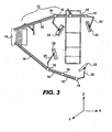
- FIGs. 2 and 3 side and top views of the medical boom 10 according to the present invention are shown respectively.
- the articulated boom arms 12 are shown extending from the stationary base 14 over the operating table.
- the display monitors 22, suspended from the articulated appendage arms 20, are thus within easy reach of the surgeon or other medical personal around the operating table.
- the ability of both the articulated boom arms 12 and the articulated appendage arms 20 to each move in the X, Y and Z directions allows the monitors 22 (or any other supported equipment) to be moved in six degrees of freedom and positioned in any desired position 360 degrees around the operating field surrounding the operating table.
- the stationary base 14 is a standing structure having a front panel 30, two side panels 32 and 34, a rear panel 36, and an optional shelf 38 (or multiple shelves) extending from one or both of the side panels 32 or 34.
- the stationary base 14 is supported on a base plate 37.
- the base plate is configured to be mounted to the floor using a fastening mechanism 39, such as a number of bolts used to secure the base plate 37 to the floor.
- the front panel 30 includes a number of recess regions 40 for housing a host of medical and electronic components (not illustrated in the figure), such as computers, video processors, communication equipment. Typically the medical and electronic components are inserted into the recess regions 40 so that their front panels are accessible. In this manner, the controls usually found on such components, such as knobs, push buttons and the like, are within easy reach by the surgeon or medical staff.
- the shelf 38 can be used for a number of purposes, such as for shelving medical equipments like scalpels and syringes or a computer keyboard and mouse for a computer housed in the stationary base 14. In the embodiment described above, the base is stationary when bolted to the floor.
- the stationary base 14 can be designed to rotate on the base plate 37 or slide back and forth on the base plate 37.
- a locking mechanism 41 such as a bolt, screw, or pin, is used to lock the stationary base 14 in place after it has been moved to a desired position thus the term "stationary” does not necessarily mean that the stationary base 14 is permanently or immovably mounted to the floor, but can be affixed to the floor but movable.
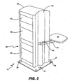
- FIG. 5 a rear perspective view of the stationary base 14 of the medical boom 10 according to the present invention is shown.
- the rear panel 36 is visible and includes a plurality of recesses 42 that provide access to the back of the medical and electrical components that may be housed in the stationary base 14.
- the recesses 42 are convenient because they allow the medical staff and other technical personal to access cables, power cords, and the like attached to the components housed in the stationary base 14.
- the rear perspective view also illustrates an arm 44, attached to side panel 34, by a joint 46, used to support the shelf 38.
- the joint 46 enables the shelf 38 to be rotated or moved into a desired position adjacent the stationary base 14.
- the stationary base 14 thus provides a central location where electronics and medical equipment can be conveniently stored.
- the electronics for the routing, switching and display of audio, video and control signals can be housed in the stationary base 14.
- the stationary base 14 can also provide access ports for digital image capture and print equipment, network equipment, Internet access, etc.
- the stationary base 14 can also provide a universal connection for providing services to the operating field, such as gases, control signals, power, and audio and visual input signals.
- a perspective view illustrating how an articulated arm 12 is attached to the stationary base 14 is shown.
- Cylindrical shaped receptacles 82 are provided at the upper corners of the stationary base 14.
- the receptacles 82 are configured to receive a pin 84 that is inserted into the receptacle 82.
- the articulated boom arm 12 also includes a cylindrical shaped receptacle 86 configured to slide over the top portion of the pin 84.
- the articulated boom arm 12 is thus designed to friction-rotate about the pin 84 so that position of the arm can be moved in the horizontal plane.
- a hinge 88 provided at the base of the articulated boom arm 12 above the cylindrical shaped receptacle 86, enables the articulated boom arm 12 to be positioned in the vertical direction.
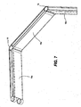
- Fig. 7 the segments 16 and joints 18 of an articulated boom arm 12 of is shown.
- three segments 16a, 16b and 16c are shown mechanically coupled by two rotating joints 18a and 18b respectively.
- the individual segments 16a, 16b and 16c can thus each be rotated about the joints 18a and 18b respectively.
- FIG. 8A an exploded view of the component parts of a segment 16 and a joint 18 according to one embodiment is shown.
- the component parts of the segment 16 include two side members 50a and 52b, a top member 52a, and a bottom member 52b.
- a conduit 82 may also be provided within the segment 16.
- the conduit 82 may be used for providing a passage way for tubing for gas delivery and recovery and electrical wires through the segment 16 (e.g., electrical signal wires, electrical power wires, gas hoses and fluid hoses).
- the conduit would run from the stationary base 14, along the length of each segment 16 of articulated arm 12, and through the appendage arms 20 to the equipment mounted onto the appendage arm 20.
- the joints 18 would include recesses to allow the conduit to pass from one segment 16 to the next and between the articulated arm 12 and the appendage arm 20.
- the four members 50a, 50b, 52a and 52b are affixed together to form a segment 16.
- the four members 50a, 50b, 52a and 52b can be made from a plastic, carbon fiber, metal or metal alloy, such as aluminum or steel. They can be affixed together in a number of various ways. With metal embodiments for example, the four members 50a, 50b, 52a and 52b can be stamped or machined individually and then affixed for example by welding, bolting or screwing, riveting the individual parts together. With plastic or carbon fiber embodiments, the four members 50a, 50b, 52a and 52b, can be formed together in a mold or the individual component parts can be affixed together using a glue or other compound for example. In an alternative embodiment, one or more of the component members 50a, 50b, 52a and 52b may be removable for servicing in the field and to provide access to any wires or tubes running through the segments 16 of the articulating boom arm 12.
- the segments 16 need not be fabricated from a number of component parts affixed together. In other embodiments, the segments 16 can be fabricated from a single component part, such as molded plastic or carbon fiber, machined metal or cast metal for example.
- each joint 18 includes two mating sleeves 18a and 18b.
- the first sleeve 18a includes an upper 54a and a lower 54b receptacle.
- the second sleeve 18b includes a middle receptacle 56.
- the sleeves 18a and 18b are mated together by inserted the middle receptacle 56 between the upper 54a and lower 54b receptacles.
- a pin 58 is then inserted through the three receptacles 54a, 54b and 56, holding the two mating sleeves 18a and 18b together.
- the pin 58 provides sufficient friction with the receptacles 54a, 54b and 56 such that the adjacent segments 16 will not move or drift unless purposely repositioned by the surgeon or other medical personal.
- FIG. 9 a perspective view of an assembled joint 18 mating two segments 16 of an articulated arm boom 12 is shown.
- the figure shows the pin 58 inserted through the receptacles 54a, 56 (receptacle 54b is not visible) of joint 18 which holds two adjacent segments 16 together.
- the two segments 16 are each free to be rotated about the pin 58 of the joint 18 as indicated by the arrows 60.
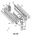
- a segment 16 according to another embodiment is shown.
- two side members 92a and 92b are provided.
- Each slide member 92a and 92b includes elongated recesses 94a and 94b respectively running the length of each member.
- the recesses 94a and 94b are provided for accommodating a conduit 82 for carrying Wires, tubes; and other passage ways for distributing electrical signal wires, electrical power wires, gas hoses and fluid hoses and the like.
- the conduit runs between segments 16 of articulated arm 12 and through the appendage arms 20 so that gas, fluid and electrical services can be provided between the base 14 and the operating field.
- Covers 96a and 96b are used to cover the recess regions 94a and 94b of side members 92a and 92b respectively.
- the side covers 96a and 96b are removable so that the conduit and any other internal wires or tubes are accessible and can be services in the field.
- the segment 16 in this embodiment also includes a bottom element 98.
- Joints 18a and 18b are provided at each end of the segment 16. Each joint has a receptacle 54a and 54b. Rather than using a single pin 58 as illustrated in Fig 8A , a multi-segment elements 100a-100d can be inserted into the receptacles 54a and 54b respectively. Specifically elements 100a and 100d are threaded and are configured to be screwed into the receptacles 54a and 54b respectively to hold two adjacent segments 16 and the components of the joint 18 together.
- the elements 92a and 92b can be fabricated from metal, plastic, carbon fiber, etc.
- the elements of the segment 16 including the side members 92a and 92b, bottom element 98 and joints 18a and 18b are fastened together using any type of fastening element, including but not limited to bolts, screws, rivets, glue or other compounds, or the like.
- the articulated appendage arm 20 includes a number of segments 70.
- the segments 70 can be fabricated in the various ways described above with respect to the segments 16 as described in relation to Fig 8A and/or Fig 8B .
- the segments 70 are connected together using a combination of pin joints 72 and rotating joints 74.
- the pin joints 72 enable the monitor 22 to be moved from side to side in the horizontal plane whereas the rotating joints enable the monitor 22 to be moved up and down in the vertical plane.
- a rotating joint 75 connects the appendage arm 20 to a boom arm 12 (not shown).
- a mounting plate 76 is provided to mount the monitor 22 onto the articulated appendage arm 20. Handles 78, attached to the mounting plate 76, are used to move and position the monitor 22.
- one or more of the monitors 22 may be a touch screen display that may be configured to control the medical and electrical components that may be housed in the stationary base 14.
- the one or monitors are configured to generate a touch-screen input display.
- the display is coupled to the electronic and medical equipment housed in the stationary base 14 through electrical wires running through the conduit 82 of the articulated arm boom(s) 12 and articulated appendage arm(s) 20 between the one or more touch screen monitors 22 and the stationary base 14.
- the touch screen displays 22 thus provide a touch panel interface that enables the operating doctor and other medical personal in the operating field to control, switch, and route signals to the electronic and medical equipment housed in the stationary base 14.
- the stationary base does not necessarily have to be fastened to the floor of an operating room. It can also be attached to or affixed to the wall of an operating room.
- the present invention has been described as a medical boom for use in a hospital operating room, it does not necessarily have to be limited to this environment. Rather the boom of the present invention may be used in a dentist office, examination rooms, veterinary clinics, surgical suites, etc. It should also be noted that there are many alternative ways of implementing the methods and apparatuses of the present invention. It is therefore intended that the following appended claims be interpreted as including all such alterations, permutations, and equivalents as fall within the scope of the present invention, as claimed.
Landscapes
- Health & Medical Sciences (AREA)
- Surgery (AREA)
- Life Sciences & Earth Sciences (AREA)
- Heart & Thoracic Surgery (AREA)
- Molecular Biology (AREA)
- Veterinary Medicine (AREA)
- Engineering & Computer Science (AREA)
- Biomedical Technology (AREA)
- Nuclear Medicine, Radiotherapy & Molecular Imaging (AREA)
- Medical Informatics (AREA)
- Public Health (AREA)
- Animal Behavior & Ethology (AREA)
- General Health & Medical Sciences (AREA)
- Pathology (AREA)
- Oral & Maxillofacial Surgery (AREA)
- Accommodation For Nursing Or Treatment Tables (AREA)
- Manipulator (AREA)
Description
- The present invention relates generally providing medical personal access to audio, visual and medical equipment in a hospital operating room, and more particularly, to a medical boom that provides a universal connection point for needed services in the operating room, including audio and video inputs and output, power, fluid delivery and recovery, and gases. The medical boom includes a stationary base with and one or more articulated arms supported by the base. The articulated arms provide 360 degree positioning of audio, visual and medical equipment around the operating field.
- State of the art hospital operating rooms now contain a wide variety of audio, visual and technology tools, such as video cameras, video recorders, microphones and voice recorders, video guided ultrasound imaging systems, lasers, cytoscanners, etc. With delicate surgery for example, a 3D video camera may be placed in or above the surgical area of the patient. The image from the camera is then transmitted to a large display, such as a flat panel, so that the operating doctor and medical staff can see an enlarged visual of the surgical area. The enlarged image makes it easier for the doctor to perform the surgery compared to relying on the naked eye.
- To accommodate all the audio, visual and medical equipment, many operating rooms have been built or retrofitted to include one or more booms suspended from the ceiling. The audio and visual equipment is then hung from the booms over the operating table. There are a number of problems, however, associated with using booms suspended from the ceiling. Most hospitals were built before many of the medical procedures commonly used today that require the use of the above described audio and visual equipment. As a result, operating rooms were not built with the requisite ceiling booms to suspend the equipment. Rather, the operating rooms have been retrofitted to install the ceiling booms. The retrofit process, however, is very complicated and expensive. Often an architect is required to draw up the plans and to provide structural engineering services. The plans are then submitted to the local building department for review. After the plans are approved, the operating room is shut down, and construction begins. The retrofit typically involves structurally reinforcing the ceiling prior to installing the booms and equipment. In addition, other trades, such as electricians, are need to upgrade the electrical power and lighting systems. A retrofit project will therefore take at least several months and cost well into the six figure dollar amount. Since the operating room can not be used during the construction, the retrofit process also results in a significant loss of revenue for the hospital. With newer hospitals, the cost and expense of designing and implementing the boom system from the ceiling during construction is also considerable.
- A stationary medical boom that can be readily installed on the floor of an existing operating room, resulting in less down time, and that has one or more articulated arms used to position video and medical equipment 360 degrees around the operating table in an operating room and is capable of providing a universal connection point for needed services in the operating room, is therefore needed.
-
US 5,824,007 describes a support stand for surgical implements. The support stand has a base and a pillar to which a plurality of support arms are attached. The support stand provides an operating environment which is particularly useful for use in laparoscopic surgery. The support stand includes positionable wrists for providing spherical motion of surgical implements about fixed points which can be made to coincide with incisions in a patient being operated on. Each wrist includes a member pivotally mounted to one of the support arms. - A first aspect of the invention provides a medical boom, comprising: a base configured to be installed into an operating room and fastened to the floor or the wall of the operating room; a plurality of boom arms, each of the plurality of boom arms being supported by the base and configured to extend over an operating table in the operating room and having at least an associated pair of boom arm segments that are coupled together by a boom arm joint; and a plurality of appendage arms, each appendage arm being mounted on an associated boom arm and having at least an associated pair of appendage arm segments coupled together by an appendage arm joint, each of the appendage arms being configured to support an associated display monitor that can be positioned in the horizontal and vertical planes substantially surrounding the operating table, wherein a first appendage arm of the plurality of appendage arms is mounted on an attachment joint mounted on one of the boom arm segments associated with a first one of the boom arms, the attachment joint being situated between first and second ends of the first one of the boom arms.
- Articulated appendage arms, extending from the boom arms, may be configured to support the audio and other medical equipment used in the operating room in the vicinity of the operating table. Both the articulated boom arm and the articulated appendage arm may be moved in either the X and/or Y directions. Consequently, the equipment supported by the appendage arm may be moved in virtually any position around the operating table. The stationary base may act as a universal connection point and may house electronic equipment for providing medical, video and data processing services for the operating field.
- The medical boom thus provides a number of advantages, including improved viewing angles for a more comfortable setting for the surgeon and medical staff. Since the stationary base is mounted onto the floor or the wall in an operating room, the aforementioned issues of using ceiling booms to suspend equipment is avoided. The medical boom of the present invention can also be installed in an operating room in a few days or less, resulting in less "down time" of the operating room. The stationary base can be used to house a host of electronic and medical equipment. It thus provides a centralized control station that can be readily accessed by the surgeon and medical staff. The medical boom can also be configured to deliver services, such as power and control electrical signals, gases, fluids, and fluid recovery from the patient.
- A second aspect of the invention provides a method, comprising: providing a stationary base configured to be installed into an operating room and fastened to the floor or the wall of the operating room; providing a plurality of boom arms, each of the plurality of boom arms being supported by the stationary base and configured to extend over an operating table in the operating room and having at least an associated pair of boom arm segments that are coupled together by a boom arm joint; and providing a plurality of appendage arms, each appendage arm being mounted on an associated boom arm and having at least an associated pair of appendage arm segments that are coupled together by an appendage arm joint, each of the appendage arms being configured to support an associated display monitor that can be positioned in the horizontal and vertical planes substantially surrounding the operating table, wherein a first appendage arm and a second appendage arm of the plurality of appendage arms are mounted off a first boom arm of the plurality of boom arms and wherein a third appendage arm and a fourth appendage arm of the plurality of appendage arms are mounted off a second boom arm of the plurality of boom arms.
- These and other features and advantages of the present invention will be presented in more detail in the following specification of the invention and the accompanying figures, which illustrate, by way of example, the principles of the invention.
- The invention, together with further advantages thereof, may best be understood by reference to the following description taken in conjunction with the accompanying drawings in which:
-
Fig. 1 illustrates a perspective view of the medical boom in an operating room according to the present invention. -
Fig. 2 illustrates a side view of the medical boom in an operating room according to the present invention. -
Fig. 3 illustrates a top-down view of the medical boom in an operating room according to the present invention. -
Fig. 4 illustrates a front perspective view of a stationary base of the medical boom according to the present invention. -
Fig. 5 illustrates a rear perspective view of the stationary base of the medical boom according to the present invention. -
Fig. 6 illustrates a perspectives view of an articulated arm attached to the base of the medical boom of the present invention. -
Fig. 7 illustrates the segments and joints of an articulated arm of the medical boom of the present invention. -
Figs. 8A and8B illustrate an exploded views of a joint used to connect two segments of the articulated arm of the medical boom according to two embodiments of the present invention. -
Fig. 9 illustrates a perspective view of the component parts of a segment and joint of the articulated arm of the medical boom of the present invention. -
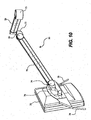
Fig. 10 shows a back perspective views of a display monitor mounted onto an appendage arm of the medical boom of the present invention. - The present invention will now be described in detail with reference to a few preferred embodiments thereof as illustrated in the accompanying drawings. In the following description, numerous specific details are set forth in order to provide a thorough understanding of the present invention. It will be apparent, however, to one skilled in the art, that the present invention may be practiced without some or all of these specific details. In other instances, well known operations have not been described in detail so not to unnecessarily obscure the present invention.
- Referring to
Fig. 1 , a perspective view of the medical boom in an operating room according to the present invention is shown. Themedical boom 10 includes a plurality of articulatedboom arms 12 mounted onto astationary base 14. Each articulatedboom arm 12 is made from a number ofarm segments 16 held together byjoints 18. A plurality of articulatedappendage arms 20 is also attached to each articulatedboom arm 12. Theappendage arms 20 are used to suspend camera, audio, visual and/or medical equipment from the articulatedboom arm 12. For example, as illustrated in the figure, four display monitors 22 are suspended from theappendage arms 20 over an operating table 24 in a hospital operating room. Both the articulatedboom arms 12 and the articulatedappendage arms 20 can be moved in the X and Y directions. As a result, the display monitors (or any other audio, video, or medical equipment) attached to the articulatedboom arms 12 and theappendage arms 20 can be readily moved to any desired horizontal and vertical position by the surgeon or support medical staff. The articulatedboom arms 12 andappendage arms 20 thus provide equipment and display positioning 360 degrees around the operating field. - The
stationary base 14 not only supports the articulatedboom arms 12, but also can be used to house a host of medical and electronic equipment, such as computers, video processors, communication equipment, a programmable control system which provides the centralized controls, and switching of equipment. The articulatedboom arms 12 and the articulatedappendage arms 20 can also be configured to carry both wiring and tubing between the electronic and medical equipment housed in thestationary base 14 and the audio, visual, and medical equipment attached to theappendage arms 20. The tubing can be used for fluid and/or gas delivery to and recovery from the patient. - According to various embodiments of the invention, the length and number of the
individual segments 16 of the articulatedboom arms 12 may vary. In the embodiment shown inFigs. 1 through 3 for example, thesegment 16 of both articulatedboom arms 12 closest thestationary base 14 are longer than theother segments 16 of each arm. In other embodiments, however, the length of eachsegment 16 can all be the same, or they can be of different lengths, withshorter segments 16 closer andlonger segments 16 farther from thebase 14, or vice versa. Further, the number ofsegments 16 per articulatedboom arm 12 may be either more or less than three as illustrated in the figures. The arrangement shown in the figures should therefore not be construed as limiting the scope of the present invention. - Referring to
Figs. 2 and3 , side and top views of themedical boom 10 according to the present invention are shown respectively. In these views, the articulatedboom arms 12 are shown extending from thestationary base 14 over the operating table. The display monitors 22, suspended from the articulatedappendage arms 20, are thus within easy reach of the surgeon or other medical personal around the operating table. The ability of both the articulatedboom arms 12 and the articulatedappendage arms 20 to each move in the X, Y and Z directions allows the monitors 22 (or any other supported equipment) to be moved in six degrees of freedom and positioned in any desired position 360 degrees around the operating field surrounding the operating table. - Referring to
Fig. 4 , a front perspective view of thestationary base 14 of the medical boom according to the present invention is shown, (for the sake of simplicity, the articulatedarms 12 are not shown in the figure). Thestationary base 14 is a standing structure having afront panel 30, twoside panels rear panel 36, and an optional shelf 38 (or multiple shelves) extending from one or both of theside panels stationary base 14 is supported on abase plate 37. The base plate is configured to be mounted to the floor using afastening mechanism 39, such as a number of bolts used to secure thebase plate 37 to the floor. Thefront panel 30 includes a number ofrecess regions 40 for housing a host of medical and electronic components (not illustrated in the figure), such as computers, video processors, communication equipment. Typically the medical and electronic components are inserted into therecess regions 40 so that their front panels are accessible. In this manner, the controls usually found on such components, such as knobs, push buttons and the like, are within easy reach by the surgeon or medical staff. Theshelf 38 can be used for a number of purposes, such as for shelving medical equipments like scalpels and syringes or a computer keyboard and mouse for a computer housed in thestationary base 14. In the embodiment described above, the base is stationary when bolted to the floor. In other embodiments, however, thestationary base 14 can be designed to rotate on thebase plate 37 or slide back and forth on thebase plate 37. Alocking mechanism 41, such as a bolt, screw, or pin, is used to lock thestationary base 14 in place after it has been moved to a desired position thus the term "stationary" does not necessarily mean that thestationary base 14 is permanently or immovably mounted to the floor, but can be affixed to the floor but movable. - Referring to
Fig. 5 , a rear perspective view of thestationary base 14 of themedical boom 10 according to the present invention is shown. In this view, therear panel 36 is visible and includes a plurality ofrecesses 42 that provide access to the back of the medical and electrical components that may be housed in thestationary base 14. Therecesses 42 are convenient because they allow the medical staff and other technical personal to access cables, power cords, and the like attached to the components housed in thestationary base 14. The rear perspective view also illustrates anarm 44, attached toside panel 34, by a joint 46, used to support theshelf 38. The joint 46 enables theshelf 38 to be rotated or moved into a desired position adjacent thestationary base 14. - The
stationary base 14 thus provides a central location where electronics and medical equipment can be conveniently stored. The electronics for the routing, switching and display of audio, video and control signals can be housed in thestationary base 14. Thestationary base 14 can also provide access ports for digital image capture and print equipment, network equipment, Internet access, etc. In addition, thestationary base 14 can also provide a universal connection for providing services to the operating field, such as gases, control signals, power, and audio and visual input signals. - Referring to
Fig. 6 , a perspective view illustrating how an articulatedarm 12 is attached to thestationary base 14 is shown. Cylindrical shapedreceptacles 82 are provided at the upper corners of thestationary base 14. Thereceptacles 82 are configured to receive apin 84 that is inserted into thereceptacle 82. The articulatedboom arm 12 also includes a cylindrical shapedreceptacle 86 configured to slide over the top portion of thepin 84. The articulatedboom arm 12 is thus designed to friction-rotate about thepin 84 so that position of the arm can be moved in the horizontal plane. In an alternative embodiment, ahinge 88, provided at the base of the articulatedboom arm 12 above the cylindrical shapedreceptacle 86, enables the articulatedboom arm 12 to be positioned in the vertical direction. - Referring to
Fig. 7 , thesegments 16 andjoints 18 of an articulatedboom arm 12 of is shown. In this Figure, threesegments rotating joints individual segments joints - Referring to
Fig. 8A , an exploded view of the component parts of asegment 16 and a joint 18 according to one embodiment is shown. The component parts of thesegment 16 include twoside members top member 52a, and abottom member 52b. Aconduit 82 may also be provided within thesegment 16. Theconduit 82 may be used for providing a passage way for tubing for gas delivery and recovery and electrical wires through the segment 16 (e.g., electrical signal wires, electrical power wires, gas hoses and fluid hoses). With such embodiments, the conduit would run from thestationary base 14, along the length of eachsegment 16 of articulatedarm 12, and through theappendage arms 20 to the equipment mounted onto theappendage arm 20. Thejoints 18 would include recesses to allow the conduit to pass from onesegment 16 to the next and between the articulatedarm 12 and theappendage arm 20. - The four
members segment 16. According to various embodiments, the fourmembers members members component members segments 16 of the articulatingboom arm 12. - It should be noted that the
segments 16 need not be fabricated from a number of component parts affixed together. In other embodiments, thesegments 16 can be fabricated from a single component part, such as molded plastic or carbon fiber, machined metal or cast metal for example. - The component parts of each joint 18 include two
mating sleeves first sleeve 18a includes an upper 54a and a lower 54b receptacle. Thesecond sleeve 18b includes amiddle receptacle 56. Whenadjacent segments 16 are assembled, thesleeves middle receptacle 56 between the upper 54a and lower 54b receptacles. Apin 58 is then inserted through the threereceptacles mating sleeves pin 58 provides sufficient friction with thereceptacles adjacent segments 16 will not move or drift unless purposely repositioned by the surgeon or other medical personal. - Referring to
Fig. 9 , a perspective view of an assembled joint 18 mating twosegments 16 of an articulatedarm boom 12 is shown. The figure shows thepin 58 inserted through thereceptacles 54a, 56 (receptacle 54b is not visible) of joint 18 which holds twoadjacent segments 16 together. The twosegments 16 are each free to be rotated about thepin 58 of the joint 18 as indicated by thearrows 60. - Referring to
Fig. 8B , asegment 16 according to another embodiment is shown. In this embodiment, twoside members slide member elongated recesses recesses conduit 82 for carrying Wires, tubes; and other passage ways for distributing electrical signal wires, electrical power wires, gas hoses and fluid hoses and the like. As previously noted, the conduit runs betweensegments 16 of articulatedarm 12 and through theappendage arms 20 so that gas, fluid and electrical services can be provided between the base 14 and the operating field.Covers 96a and 96b are used to cover therecess regions side members segment 16 in this embodiment also includes a bottom element 98.Joints segment 16. Each joint has areceptacle single pin 58 as illustrated inFig 8A , a multi-segment elements 100a-100d can be inserted into thereceptacles elements 100a and 100d are threaded and are configured to be screwed into thereceptacles adjacent segments 16 and the components of the joint 18 together. - In various other embodiments, the
elements segment 16 including theside members joints - Referring to
Fig. 10 , a rear view of adisplay monitor 22 mounted onto an articulatedappendage arm 20 according to the present invention is shown. The articulatedappendage arm 20 includes a number ofsegments 70. Thesegments 70 can be fabricated in the various ways described above with respect to thesegments 16 as described in relation toFig 8A and/orFig 8B . Thesegments 70 are connected together using a combination ofpin joints 72 androtating joints 74. The pin joints 72 enable themonitor 22 to be moved from side to side in the horizontal plane whereas the rotating joints enable themonitor 22 to be moved up and down in the vertical plane. A rotating joint 75 connects theappendage arm 20 to a boom arm 12 (not shown). A mountingplate 76 is provided to mount themonitor 22 onto the articulatedappendage arm 20.Handles 78, attached to the mountingplate 76, are used to move and position themonitor 22. - In one embodiment, one or more of the
monitors 22 may be a touch screen display that may be configured to control the medical and electrical components that may be housed in thestationary base 14. In this embodiment, the one or monitors are configured to generate a touch-screen input display. The display is coupled to the electronic and medical equipment housed in thestationary base 14 through electrical wires running through theconduit 82 of the articulated arm boom(s) 12 and articulated appendage arm(s) 20 between the one or more touch screen monitors 22 and thestationary base 14. The touch screen displays 22 thus provide a touch panel interface that enables the operating doctor and other medical personal in the operating field to control, switch, and route signals to the electronic and medical equipment housed in thestationary base 14. - While this invention has been described in terms of several preferred embodiments, there are alteration, permutations, and equivalents, which fall within the scope of this invention. For example, the stationary base does not necessarily have to be fastened to the floor of an operating room. It can also be attached to or affixed to the wall of an operating room. Further, while the present invention has been described as a medical boom for use in a hospital operating room, it does not necessarily have to be limited to this environment. Rather the boom of the present invention may be used in a dentist office, examination rooms, veterinary clinics, surgical suites, etc. It should also be noted that there are many alternative ways of implementing the methods and apparatuses of the present invention. It is therefore intended that the following appended claims be interpreted as including all such alterations, permutations, and equivalents as fall within the scope of the present invention, as claimed.
Claims (34)
- A medical boom (10), comprising:a base (14) configured to be installed into an operating room and fastened to the floor or the wall of the operating room;a plurality of boom arms (12), each of the plurality of boom arms being supported by the base and configured to extend over an operating table (24) in the operating room and having at least an associated pair of boom arm segments (16) that are coupled together by a boom arm joint (18); anda plurality of appendage arms (20), each appendage arm being mounted on an associated boom arm and having at least an associated pair of appendage arm segments (70) coupled together by an appendage arm joint (74), each of the appendage arms being configured to support an associated display monitor (22) that can be positioned in the horizontal and vertical planes substantially surrounding the operating table, wherein a first appendage arm (20) of the plurality of appendage arms is mounted on an attachment joint (75) mounted on one of the boom arm segments (16) associated with a first one of the boom arms (12), the attachment joint being situated between first and second ends of the first one of the boom arms.
- The medical boom (10) of claim 1, further comprising:a first joint (84, 86, 88) to mount the boom arm onto the base (14), the first joint enabling the boom arm to be moved in the horizontal and/or vertical planes; anda second joint (75) to mount the articulated appendage arm (20) onto the articulated boom arm (12), the joint enabling the appendage arm to be moved in the horizontal and/or vertical planes.
- The medical boom (10) of claim 1, wherein the base (14) further comprises one or more recess regions (40) configured to house medical and/or electronic equipment.
- The medical boom (10) of claim 1, wherein the base (14) further comprises a base plate (37) and a fastening element (39) configured to secure the base plate to the floor or wall of the operating room.
- The medical boom (10) of claim 1, wherein the boom arm is an articulated boom arm (12) having a plurality of segments (16), the plurality of segments being mechanically coupled together by a plurality of joints (18) respectively.
- The medical boom (10) of claim 5, wherein the plurality of segments (16) are each configured to rotate about the plurality of joints in the horizontal and/or vertical planes respectively.
- The medical boom (10) of claim 5, wherein the individual segments (16) each include a plurality of component parts affixed together, the plurality of components being made from one or more of the following types of materials: metal, metal alloy, plastic, or carbon fiber.
- The medical boom (10) of claim 5, wherein the plurality of joints (18) each comprises one of the following types of joints: rotating joints and pin joints.
- The medical boom (10) of claim 1, wherein the articulated appendage arm (20) comprises a plurality of segments (70), the plurality of segments being mechanically coupled together by a plurality of joints (74) so that the plurality of segments can each rotate about the plurality of joints in the horizontal and/or vertical planes respectively.
- The medical boom (10) of claim 9, wherein each of the plurality of segments (70) of the articulated appendage arm (20) comprise a plurality of component parts affixed together, the plurality of components being made from one or more,of the following types of materials: metal, metal alloy, plastic, or carbon fiber.
- The medical boom (10) of claim 9, wherein the plurality of joints comprises one of the following types of joints: rotating joints and pin joints.
- The medical boom (10) of claim 1, further comprising a mounting plate (76) coupled to the articulated appendage arm (20), the equipment used in the operating room configured to be mounted onto the mounting plate.
- The medical boom (10) of claim 1, further comprises a conduit (82) for routing one or more of the following through the boom arm (12) and the articulated appendage arm (20): electrical signal wires, electrical power wires, gas hoses and/or fluid hoses.
- The medical boom (10) of claim 1, wherein the base (14) is a structure having a front panel (30) and a rear panel (36) and two side panels (32, 34) and the front panel (30) and the rear panel (36) have one or more recesses (40, 42) to access medical and/or electronic equipment housed in the base.
- The medical boom (10) of claim 1, wherein the equipment comprises one or more of the following: a video display monitor, a video camera, audio equipment and/or a touch screen monitor configured to allow medical personal in the operating room to control electrical and medical equipment housed in the base.
- The medical boom of claim 1, and further comprising:a first mounting element coupled to a first boom arm segment for supporting a first display monitor capable of displaying video images, such that the first display monitor may be positioned in three degrees of freedom around the operating field surrounding the operating table in the operating room by manipulating the position of the boom arm and the first mounting element; anda second mounting element coupled to a second boom arm segment for supporting a second display monitor capable of displaying video images, such that the second display monitor may be positioned in three degrees of freedom around the operating field in the operating room by manipulating the position of the boom arm and the second mounting element.
- The medical boom (10) of claim 16, wherein the boom arm (12) is an articulated boom arm comprising a plurality of segments (16) and a plurality of joints (18) that enable the plurality of segments of the boom arm to be selectively positioned in the horizontal and/or vertical planes so that the equipment can be positioned in the three degrees of freedom around the operating field.
- The medical boom (10) of claim 16, wherein the mounting element is configured to mount one of the following types of equipment onto the boom arm: a video display, a video camera, audio equipment, and/or a touch screen monitor configured to allow medical personal in the operating room to control electrical and medical equipment housed in the base.
- The medical boom (10) of claim 16, wherein the boom arm further comprises one or more of the following:(i) one or more gas conduit (84) to provide or recover gas to and from the operating field;(ii) one or more a fluid conduit (84) to supply and/or recover fluids from the operating field; and/or(iii) one or more a wire conduit (84) for providing electrical power and/or signal wires between the equipment mounted on the mounting element and electrical equipment housed in the base.
- The medical boom (10) of claim 16, wherein the base is further configured to house electronic equipment for providing medical, video and data processing services in the operating room.
- A method, comprising:providing a stationary base (14) configured to be installed into an operating room and fastened to the floor or the wall of the operating room;providing a plurality of boom arms (12), each of the plurality of boom arms being supported by the stationary base (14) and configured to extend over an operating table (24) in the operating room and having at least an associated pair of boom arm segments (16) that are coupled together by a boom arm joint (18); andproviding a plurality of appendage arms (20), each appendage arm being mounted on an associated boom arm and having at least an associated pair of appendage arm segments (70) that are coupled together by an appendage arm joint (72, 74), each of the appendage arms (20) being configured to support an associated display monitor (22) that can be positioned in the horizontal and vertical planes substantially surrounding the operating table, wherein a first appendage arm and a second appendage arm of the plurality of appendage arms are mounted off a first boom arm of the plurality of boom arms and wherein a third appendage arm and a fourth appendage arm of the plurality of appendage arms are mounted off a second boom arm of the plurality of boom arms.
- The method of claim 21, further comprising providing a first joint to mount the boom arm onto the base and providing a second joint to mount the articulated appendage arm onto the boom arm.
- The method of claim 21, further comprising providing in the base one or more recess regions configured to house medical and/or electronic equipment.
- The method of claim 21, further comprising providing a base plate and a fastening element configured to secure the base plate to the floor or wall of the operating room.
- The method of claim 21, wherein the provided boom arm is an articulated boom arm having a plurality of segments, the plurality of segments being mechanically coupled together by a plurality of joints respectively.
- The method of claim 21, further providing a mounting plate coupled to the provided articulated appendage arm, the provided equipment used in the operating room being configured to be mounted onto the provided mounting plate, the provided equipment including one or more of the following: a video display monitor, a video camera, audio equipment and/or a touch screen monitor configured to allow medical personal in the operating room to control electrical and medical equipment provided in the base.
- The method of claim 21, further providing one or more conduits through the boom arm and the articulated appendage arm for providing one or more of the following between the equipment supported by the boom arm and the articulated appendage arm and the base: electrical signal wires, electrical power wires, gas hoses and fluid hoses.
- The method of claim 21, wherein the provided boom arm and the provided articulated appendage arm enable the provided equipment to be positioned in three degrees of freedom in the operating field surrounding the operating table in the operating room.
- The method of claim 21, wherein the provided boom arm and the provided articulated appendage arm enable the provided equipment to be selectively positioned in the horizontal plane and/or the vertical plane around the operating field in the operating room.
- The method of claim 21, further comprising providing the capability to house electronic equipment in the base for providing medical, video and data processing services to the operating field.
- The method of claim 21, further comprising providing the capability to control the electronic equipment in the base through an input touch monitor mounted of the boom arm and positioned in the vicinity of the operating field in the operating room.
- The medical boom (10) of claim 1 or 16, wherein the base (14) is further configured to support up to four of the boom arms (12) and wherein up to four boom arms each attach to a top corner (82) of the base respectively.
- The medical boom (10) as claimed in claim 1, 16 or 32, wherein one of the appendage arms (20) is mounted on the boom arm joint (18) of one of the boom arms (12), the one of the boom arms having a first end and a second end, the boom arm joint of the one of the boom arms being situated between the first and second ends of the one of the boom arms.
- The medical boom as claimed in claim 16, wherein the first mounting element is mounted on a distal end of the first one of the boom arm segments.
Applications Claiming Priority (2)
| Application Number | Priority Date | Filing Date | Title |
|---|---|---|---|
| US11/093,075 US7516924B2 (en) | 2005-03-28 | 2005-03-28 | Articulated boom for positioning video and medical equipment in hospital operating rooms |
| PCT/US2006/003708 WO2006104566A2 (en) | 2005-03-28 | 2006-02-01 | Articulated boom for positioning video and medical equipment in hospital operating rooms |
Publications (3)
| Publication Number | Publication Date |
|---|---|
| EP1863424A2 EP1863424A2 (en) | 2007-12-12 |
| EP1863424A4 EP1863424A4 (en) | 2013-03-27 |
| EP1863424B1 true EP1863424B1 (en) | 2015-10-14 |
Family
ID=37053836
Family Applications (1)
| Application Number | Title | Priority Date | Filing Date |
|---|---|---|---|
| EP06734227.9A Expired - Lifetime EP1863424B1 (en) | 2005-03-28 | 2006-02-01 | Articulated boom for positioning video and medical equipment in hospital operating rooms |
Country Status (5)
| Country | Link |
|---|---|
| US (1) | US7516924B2 (en) |
| EP (1) | EP1863424B1 (en) |
| JP (1) | JP5253150B2 (en) |
| CN (1) | CN101621946B (en) |
| WO (1) | WO2006104566A2 (en) |
Families Citing this family (49)
| Publication number | Priority date | Publication date | Assignee | Title |
|---|---|---|---|---|
| WO2003092341A2 (en) * | 2002-04-24 | 2003-11-06 | Innovative Office Products, Inc. | Multiple electronic device reorienting support |
| US8102333B2 (en) * | 2005-04-28 | 2012-01-24 | Sony Corporation | Display device securing mechanism and display system that rotates display devices around a rotational axis |
| US7922132B2 (en) * | 2007-01-24 | 2011-04-12 | Humanscale Corporation | Accessory holder |
| US20090173847A1 (en) * | 2007-01-24 | 2009-07-09 | Wolfgang Dittmer | Accessory Holder |
| US20080221930A1 (en) | 2007-03-09 | 2008-09-11 | Spacelabs Medical, Inc. | Health data collection tool |
| WO2008157813A1 (en) * | 2007-06-20 | 2008-12-24 | Surgmatix, Inc. | Surgical data monitoring and display system |
| DE102007048598A1 (en) * | 2007-10-10 | 2009-04-23 | Ondal Industrietechnik Gmbh | suspension |
| US20090173846A1 (en) * | 2008-01-09 | 2009-07-09 | Allan Katz | Medical boom |
| US10875182B2 (en) | 2008-03-20 | 2020-12-29 | Teladoc Health, Inc. | Remote presence system mounted to operating room hardware |
| GB2460405A (en) * | 2008-05-28 | 2009-12-02 | Peter Ligertwood | Modular mounting system unit |
| US20100123049A1 (en) * | 2008-11-20 | 2010-05-20 | Lehman Vincent M | Medical gas hose support system |
| US8384755B2 (en) | 2009-08-26 | 2013-02-26 | Intouch Technologies, Inc. | Portable remote presence robot |
| IN2012DN03164A (en) * | 2009-10-16 | 2015-09-18 | Spacelabs Healthcare Llc | |
| BR112012012147A2 (en) | 2009-10-16 | 2019-09-24 | Spacelabs Healthcare Llc | improved light flow tube |
| US9604020B2 (en) | 2009-10-16 | 2017-03-28 | Spacelabs Healthcare Llc | Integrated, extendable anesthesia system |
| US9022492B2 (en) * | 2010-12-17 | 2015-05-05 | Spacelabs Healthcare Llc | Sliding track and pivot mounting system for displays on anesthesia machines |
| KR100976344B1 (en) * | 2009-12-02 | 2010-08-16 | 도상희 | Supporter for medical imaging apparatus using multi-step and mult-axis |
| US8670017B2 (en) | 2010-03-04 | 2014-03-11 | Intouch Technologies, Inc. | Remote presence system including a cart that supports a robot face and an overhead camera |
| WO2011119512A1 (en) | 2010-03-21 | 2011-09-29 | Spacelabs Healthcare, Llc | Multi-display bedside monitoring system |
| US9316346B2 (en) | 2010-06-09 | 2016-04-19 | Colebrook Bosson Saunders (Products) Limited | Support system |
| US9074721B2 (en) | 2010-06-09 | 2015-07-07 | Alex Lau | Support system |
| USD684982S1 (en) | 2010-08-11 | 2013-06-25 | Colebrook Bosson Saunders (Products) Limited | Display support with indicator window |
| WO2012068567A1 (en) | 2010-11-19 | 2012-05-24 | Spacelabs Healthcare, Llc | Dual serial bus interface |
| US9629566B2 (en) | 2011-03-11 | 2017-04-25 | Spacelabs Healthcare Llc | Methods and systems to determine multi-parameter managed alarm hierarchy during patient monitoring |
| US8836751B2 (en) | 2011-11-08 | 2014-09-16 | Intouch Technologies, Inc. | Tele-presence system with a user interface that displays different communication links |
| GB2499462A (en) * | 2012-02-20 | 2013-08-21 | Hoerbiger Uk Ltd | Cantilevered articulated loading device |
| KR102263247B1 (en) | 2012-10-24 | 2021-06-10 | 스트리커 코포레이션 | Waste collection system for medical/surgical waste having a mobile cart with a vacuum source and a mobile cart with a waste container that is coupled to the act with the suction pump |
| US10987026B2 (en) | 2013-05-30 | 2021-04-27 | Spacelabs Healthcare Llc | Capnography module with automatic switching between mainstream and sidestream monitoring |
| DE102013219415B4 (en) | 2013-09-26 | 2019-11-07 | Siemens Healthcare Gmbh | Tripod with device for deformation compensation |
| KR101553640B1 (en) | 2014-01-17 | 2015-09-16 | 오스템임플란트 주식회사 | Unit chair monitor arm |
| CN103932791B (en) * | 2014-03-13 | 2016-02-24 | 西安交通大学 | A kind of intelligent surgical operation process video recording device |
| CN106794103B (en) * | 2014-07-30 | 2020-11-03 | 欧达尔医疗系统有限责任公司 | Shaft sleeve, bearing arm and bearing system for medical hanger device |
| KR102617042B1 (en) | 2014-10-27 | 2023-12-27 | 인튜어티브 서지컬 오퍼레이션즈 인코포레이티드 | System and method for registering to a surgical table |
| WO2016069660A1 (en) | 2014-10-27 | 2016-05-06 | Intuitive Surgical Operations, Inc. | System and method for monitoring control points during reactive motion |
| CN107072724B (en) | 2014-10-27 | 2019-10-25 | 直观外科手术操作公司 | System and method for device interference compensation |
| EP3212151B1 (en) | 2014-10-27 | 2020-07-29 | Intuitive Surgical Operations, Inc. | System for integrated surgical table motion |
| CN111166476B (en) | 2014-10-27 | 2023-05-02 | 直观外科手术操作公司 | Medical devices with active brake release controls |
| WO2016069648A1 (en) | 2014-10-27 | 2016-05-06 | Intuitive Surgical Operations, Inc. | System and method for integrated surgical table |
| US9549609B2 (en) * | 2014-10-31 | 2017-01-24 | MyWorld Mediastudio | Mobile mulimedia workstation |
| EP3118509A1 (en) * | 2015-07-17 | 2017-01-18 | Norsap AP | A device for holding two or more monitors at an operator chair |
| DE102017000851B4 (en) * | 2017-01-31 | 2020-12-10 | Drägerwerk AG & Co. KGaA | Flexible console system for medical devices |
| CN109276392B (en) * | 2017-07-22 | 2023-12-29 | 万盛精密钣金江苏有限公司 | A kind of medical energy pendant tower |
| US11123249B2 (en) | 2018-05-02 | 2021-09-21 | Stryker Corporation | Vertically adjustable boom head and cable management therefor |
| CN109009821A (en) * | 2018-08-29 | 2018-12-18 | 深圳市美格尔医疗设备股份有限公司 | Bridge type tower crane |
| WO2020117587A2 (en) | 2018-12-05 | 2020-06-11 | Stryker Corporation | A medical waste management system integrated within a medical facility |
| US12102416B2 (en) | 2019-06-26 | 2024-10-01 | Spacelabs Healthcare L.L.C. | Using data from a body worn sensor to modify monitored physiological data |
| JP7576264B2 (en) * | 2020-01-29 | 2024-10-31 | 株式会社ニシウラ | Medical equipment installation equipment |
| CN115789443B (en) * | 2022-11-21 | 2023-11-14 | 深圳市安立信电子有限公司 | Medical display with gamma automatic calibration and debugging functions |
| EP4549801A1 (en) * | 2023-11-06 | 2025-05-07 | Koninklijke Philips N.V. | Monitor support |
Family Cites Families (40)
| Publication number | Priority date | Publication date | Assignee | Title |
|---|---|---|---|---|
| US4548373A (en) * | 1983-03-22 | 1985-10-22 | Tokyo Kogaku Kikai Kabushiki Kaisha | Medical equipment supporting device |
| JPS6456409A (en) * | 1987-05-29 | 1989-03-03 | Mitaka Koki Kk | Stand device for medical optical machinery |
| US5061018A (en) * | 1990-04-02 | 1991-10-29 | Time Surgical, Inc. | Microscope accessory equipment container |
| DE9218373U1 (en) | 1992-12-14 | 1994-01-27 | Dornier Medizintechnik GmbH, 81663 München | Workplace for minimally invasive surgery |
| JP2825721B2 (en) * | 1992-12-28 | 1998-11-18 | 三鷹光器株式会社 | Medical optical equipment stand device |
| DE4416178B4 (en) * | 1993-05-07 | 2007-11-08 | Olympus Optical Co., Ltd. | Surgical microscope |
| JP3402797B2 (en) * | 1994-11-07 | 2003-05-06 | オリンパス光学工業株式会社 | Endoscope image display system |
| DE19681463C2 (en) * | 1996-04-23 | 2003-08-14 | Kokuyo Co | Support device for an object |
| US5824007A (en) * | 1996-12-03 | 1998-10-20 | Simon Fraser University | Adjustable surgical stand |
| EP0876799A3 (en) | 1997-05-07 | 2001-01-24 | Siemens Aktiengesellschaft | Medical-technical work station |
| US6351678B1 (en) | 1997-11-07 | 2002-02-26 | Hill-Rom Services, Inc. | Medical equipment controller |
| DE19807241C2 (en) | 1998-02-20 | 2002-06-20 | Siemens Ag | Medical workplace |
| DE19807243C2 (en) * | 1998-02-20 | 2002-07-11 | Siemens Ag | Medical workplace |
| DE19807242C2 (en) | 1998-02-20 | 2002-07-11 | Siemens Ag | Medical-technical system workstation |
| US6012821A (en) * | 1998-03-30 | 2000-01-11 | Hill-Rom, Inc. | Support arm for surgical light apparatus |
| US6328458B1 (en) * | 1998-03-30 | 2001-12-11 | Hill-Rom Services, Inc. | Support arm for surgical light apparatus |
| JP2968513B1 (en) * | 1998-04-08 | 1999-10-25 | 三鷹光器株式会社 | Stand device with monitor |
| US6505774B1 (en) * | 1998-12-09 | 2003-01-14 | Miti Manufacturing Company | Automated fee collection and parking ticket dispensing machine |
| US6661571B1 (en) * | 1999-09-21 | 2003-12-09 | Olympus Optical Co., Ltd. | Surgical microscopic system |
| FI111047B (en) * | 1999-12-01 | 2003-05-30 | Instrumentarium Corp | Control arm system for connection of various medical photography devices leveled to a support structure |
| US20010034530A1 (en) * | 2000-01-27 | 2001-10-25 | Malackowski Donald W. | Surgery system |
| US6639789B2 (en) * | 2000-07-12 | 2003-10-28 | Karl Storz Gmbh & Co. Kg | Instrument and service unit for a surgical operating area |
| DE10040343B4 (en) * | 2000-08-17 | 2004-04-15 | Mavig Gmbh | Carrier for carrying at least one device |
| US6896233B2 (en) * | 2000-08-17 | 2005-05-24 | Mavig Gmbh | Support for medical equipment |
| AU2001295433A1 (en) | 2000-10-09 | 2002-04-22 | Benca Technology Aps | A surgical workstation |
| US6793625B2 (en) * | 2000-11-13 | 2004-09-21 | Draeger Medical Systems, Inc. | Method and apparatus for concurrently displaying respective images representing real-time data and non real-time data |
| JP3579379B2 (en) * | 2001-08-10 | 2004-10-20 | 株式会社東芝 | Medical manipulator system |
| US7097145B2 (en) * | 2001-09-14 | 2006-08-29 | Hill-Rom Services, Inc. | Support arm for a surgical theater system |
| AU2002354031B2 (en) * | 2001-11-05 | 2007-08-30 | American Sterilizer Company | Medical suspension system with two spindles |
| JP3905393B2 (en) * | 2002-02-07 | 2007-04-18 | オリンパス株式会社 | Surgical device |
| US7246780B2 (en) * | 2002-05-01 | 2007-07-24 | Innovative Office Products, Inc. | Stackable multiple support arm for electronic devices |
| CN2549925Y (en) * | 2002-05-13 | 2003-05-14 | 梁桂秋 | Rotary hanging arm for surgical room |
| CN2558347Y (en) * | 2002-08-19 | 2003-07-02 | 烟台冰科氧业有限公司 | Medical arm crane |
| US20040195471A1 (en) * | 2003-01-09 | 2004-10-07 | Sachen Richard John | Dual flat panel monitor stand |
| US6857609B2 (en) * | 2003-01-09 | 2005-02-22 | The Johns Hopkins University | Medical imaging environment compatible positioning arm |
| CA2518160A1 (en) * | 2003-03-18 | 2004-09-30 | Hill-Rom Services, Inc. | Radial arm system for patient care equipment |
| CN100447797C (en) * | 2003-03-28 | 2008-12-31 | 卡迪纳尔健康303公司 | Infusion Data Communication System |
| JP2005013715A (en) * | 2003-06-05 | 2005-01-20 | Olympus Corp | Observation system |
| DE10353961B4 (en) * | 2003-11-19 | 2005-09-22 | Carl Zeiss | Microscopy system and method for controlling a microscopy system |
| CA2521790A1 (en) * | 2004-09-30 | 2006-03-30 | Compx International Inc. | Support for flat monitors |
-
2005
- 2005-03-28 US US11/093,075 patent/US7516924B2/en not_active Expired - Fee Related
-
2006
- 2006-02-01 CN CN2006800103938A patent/CN101621946B/en not_active Expired - Fee Related
- 2006-02-01 JP JP2008504032A patent/JP5253150B2/en not_active Expired - Fee Related
- 2006-02-01 WO PCT/US2006/003708 patent/WO2006104566A2/en not_active Ceased
- 2006-02-01 EP EP06734227.9A patent/EP1863424B1/en not_active Expired - Lifetime
Also Published As
| Publication number | Publication date |
|---|---|
| EP1863424A4 (en) | 2013-03-27 |
| US7516924B2 (en) | 2009-04-14 |
| EP1863424A2 (en) | 2007-12-12 |
| WO2006104566A2 (en) | 2006-10-05 |
| JP2008538301A (en) | 2008-10-23 |
| US20060226308A1 (en) | 2006-10-12 |
| JP5253150B2 (en) | 2013-07-31 |
| CN101621946B (en) | 2012-05-02 |
| WO2006104566A3 (en) | 2009-04-16 |
| CN101621946A (en) | 2010-01-06 |
Similar Documents
| Publication | Publication Date | Title |
|---|---|---|
| US7516924B2 (en) | Articulated boom for positioning video and medical equipment in hospital operating rooms | |
| US20090026901A1 (en) | Medical Servicing System | |
| US20100115750A1 (en) | Medical boom with articulated arms and a base with preconfigured removable modular racks used for storing electronic and utility equipment | |
| US11553160B1 (en) | Systems and methods for imaging communication and control | |
| US7652876B2 (en) | Graphics and monitor controller assemblies in multi-screen display systems | |
| JP2008538301A5 (en) | ||
| US20040244512A1 (en) | System operating unit | |
| US6466432B1 (en) | Instrument and service unit for a surgical operating area | |
| US11415264B2 (en) | Bracket assembly and method for mounting electrical equipment in between a monitor and a supporting structure | |
| US20130314300A1 (en) | Graphics and Monitor Controller Assemblies in Multi-Screen Display Systems | |
| WO2006078961A2 (en) | Articulated mounting systems and bearings for joints thereof | |
| CN111166476B (en) | Medical devices with active brake release controls | |
| WO2003107157A2 (en) | Lcd system having integrated cpu | |
| CN1079312A (en) | The workstation of operator | |
| US20110101179A1 (en) | Tv support structure with latching mechanism | |
| US8922457B2 (en) | Controller and graphics assemblies in multi-screen display systems | |
| JP2002132173A (en) | Display device | |
| US20100243823A1 (en) | Ceiling-mounted docking device | |
| CA2462648C (en) | Video/data quick connect system for monitor suspension arms | |
| US20100190131A1 (en) | Rear delivery unit with infrastructure in cabinet drawer | |
| US5895886A (en) | Supply unit | |
| US10021987B2 (en) | Device for holding two or more monitors at an operator chair | |
| CN219594815U (en) | Knapsack device and doctor control cabinet | |
| CN1159745A (en) | Screen workplace | |
| JP6623129B2 (en) | Information display board |
Legal Events
| Date | Code | Title | Description |
|---|---|---|---|
| PUAI | Public reference made under article 153(3) epc to a published international application that has entered the european phase |
Free format text: ORIGINAL CODE: 0009012 |
|
| 17P | Request for examination filed |
Effective date: 20071018 |
|
| AK | Designated contracting states |
Kind code of ref document: A2 Designated state(s): AT BE BG CH CY CZ DE DK EE ES FI FR GB GR HU IE IS IT LI LT LU LV MC NL PL PT RO SE SI SK TR |
|
| AX | Request for extension of the european patent |
Extension state: AL BA HR MK YU |
|
| DAX | Request for extension of the european patent (deleted) | ||
| R17D | Deferred search report published (corrected) |
Effective date: 20090416 |
|
| RIC1 | Information provided on ipc code assigned before grant |
Ipc: A47F 5/00 20060101AFI20090422BHEP Ipc: F16M 11/00 20060101ALI20090422BHEP Ipc: A47F 7/00 20060101ALI20090422BHEP Ipc: F16M 13/00 20060101ALI20090422BHEP |
|
| REG | Reference to a national code |
Ref country code: DE Ref legal event code: R079 Ref document number: 602006046930 Country of ref document: DE Free format text: PREVIOUS MAIN CLASS: A61G0013100000 Ipc: A47F0005000000 |
|
| A4 | Supplementary search report drawn up and despatched |
Effective date: 20130227 |
|
| RIC1 | Information provided on ipc code assigned before grant |
Ipc: A61B 19/02 20060101ALI20130221BHEP Ipc: A47F 5/00 20060101AFI20130221BHEP Ipc: F16M 11/00 20060101ALI20130221BHEP Ipc: A61B 19/00 20060101ALI20130221BHEP Ipc: A47F 7/00 20060101ALI20130221BHEP Ipc: F16M 13/00 20060101ALI20130221BHEP |
|
| RAP1 | Party data changed (applicant data changed or rights of an application transferred) |
Owner name: COMP-VIEW, INC. |
|
| GRAP | Despatch of communication of intention to grant a patent |
Free format text: ORIGINAL CODE: EPIDOSNIGR1 |
|
| INTG | Intention to grant announced |
Effective date: 20141203 |
|
| GRAP | Despatch of communication of intention to grant a patent |
Free format text: ORIGINAL CODE: EPIDOSNIGR1 |
|
| INTG | Intention to grant announced |
Effective date: 20150417 |
|
| GRAS | Grant fee paid |
Free format text: ORIGINAL CODE: EPIDOSNIGR3 |
|
| GRAA | (expected) grant |
Free format text: ORIGINAL CODE: 0009210 |
|
| AK | Designated contracting states |
Kind code of ref document: B1 Designated state(s): AT BE BG CH CY CZ DE DK EE ES FI FR GB GR HU IE IS IT LI LT LU LV MC NL PL PT RO SE SI SK TR |
|
| REG | Reference to a national code |
Ref country code: GB Ref legal event code: FG4D |
|
| REG | Reference to a national code |
Ref country code: AT Ref legal event code: REF Ref document number: 754452 Country of ref document: AT Kind code of ref document: T Effective date: 20151015 Ref country code: CH Ref legal event code: EP |
|
| REG | Reference to a national code |
Ref country code: IE Ref legal event code: FG4D |
|
| REG | Reference to a national code |
Ref country code: DE Ref legal event code: R096 Ref document number: 602006046930 Country of ref document: DE |
|
| REG | Reference to a national code |
Ref country code: NL Ref legal event code: MP Effective date: 20151014 |
|
| REG | Reference to a national code |
Ref country code: LT Ref legal event code: MG4D |
|
| REG | Reference to a national code |
Ref country code: AT Ref legal event code: MK05 Ref document number: 754452 Country of ref document: AT Kind code of ref document: T Effective date: 20151014 |
|
| PG25 | Lapsed in a contracting state [announced via postgrant information from national office to epo] |
Ref country code: LT Free format text: LAPSE BECAUSE OF FAILURE TO SUBMIT A TRANSLATION OF THE DESCRIPTION OR TO PAY THE FEE WITHIN THE PRESCRIBED TIME-LIMIT Effective date: 20151014 Ref country code: IS Free format text: LAPSE BECAUSE OF FAILURE TO SUBMIT A TRANSLATION OF THE DESCRIPTION OR TO PAY THE FEE WITHIN THE PRESCRIBED TIME-LIMIT Effective date: 20160214 Ref country code: IT Free format text: LAPSE BECAUSE OF FAILURE TO SUBMIT A TRANSLATION OF THE DESCRIPTION OR TO PAY THE FEE WITHIN THE PRESCRIBED TIME-LIMIT Effective date: 20151014 Ref country code: NL Free format text: LAPSE BECAUSE OF FAILURE TO SUBMIT A TRANSLATION OF THE DESCRIPTION OR TO PAY THE FEE WITHIN THE PRESCRIBED TIME-LIMIT Effective date: 20151014 Ref country code: ES Free format text: LAPSE BECAUSE OF FAILURE TO SUBMIT A TRANSLATION OF THE DESCRIPTION OR TO PAY THE FEE WITHIN THE PRESCRIBED TIME-LIMIT Effective date: 20151014 |
|
| PG25 | Lapsed in a contracting state [announced via postgrant information from national office to epo] |
Ref country code: GR Free format text: LAPSE BECAUSE OF FAILURE TO SUBMIT A TRANSLATION OF THE DESCRIPTION OR TO PAY THE FEE WITHIN THE PRESCRIBED TIME-LIMIT Effective date: 20160115 Ref country code: LV Free format text: LAPSE BECAUSE OF FAILURE TO SUBMIT A TRANSLATION OF THE DESCRIPTION OR TO PAY THE FEE WITHIN THE PRESCRIBED TIME-LIMIT Effective date: 20151014 Ref country code: PL Free format text: LAPSE BECAUSE OF FAILURE TO SUBMIT A TRANSLATION OF THE DESCRIPTION OR TO PAY THE FEE WITHIN THE PRESCRIBED TIME-LIMIT Effective date: 20151014 Ref country code: AT Free format text: LAPSE BECAUSE OF FAILURE TO SUBMIT A TRANSLATION OF THE DESCRIPTION OR TO PAY THE FEE WITHIN THE PRESCRIBED TIME-LIMIT Effective date: 20151014 Ref country code: FI Free format text: LAPSE BECAUSE OF FAILURE TO SUBMIT A TRANSLATION OF THE DESCRIPTION OR TO PAY THE FEE WITHIN THE PRESCRIBED TIME-LIMIT Effective date: 20151014 Ref country code: PT Free format text: LAPSE BECAUSE OF FAILURE TO SUBMIT A TRANSLATION OF THE DESCRIPTION OR TO PAY THE FEE WITHIN THE PRESCRIBED TIME-LIMIT Effective date: 20160215 Ref country code: BE Free format text: LAPSE BECAUSE OF NON-PAYMENT OF DUE FEES Effective date: 20160229 Ref country code: SE Free format text: LAPSE BECAUSE OF FAILURE TO SUBMIT A TRANSLATION OF THE DESCRIPTION OR TO PAY THE FEE WITHIN THE PRESCRIBED TIME-LIMIT Effective date: 20151014 |
|
| REG | Reference to a national code |
Ref country code: DE Ref legal event code: R097 Ref document number: 602006046930 Country of ref document: DE |
|
| PG25 | Lapsed in a contracting state [announced via postgrant information from national office to epo] |
Ref country code: CZ Free format text: LAPSE BECAUSE OF FAILURE TO SUBMIT A TRANSLATION OF THE DESCRIPTION OR TO PAY THE FEE WITHIN THE PRESCRIBED TIME-LIMIT Effective date: 20151014 |
|
| PLBE | No opposition filed within time limit |
Free format text: ORIGINAL CODE: 0009261 |
|
| STAA | Information on the status of an ep patent application or granted ep patent |
Free format text: STATUS: NO OPPOSITION FILED WITHIN TIME LIMIT |
|
| PG25 | Lapsed in a contracting state [announced via postgrant information from national office to epo] |
Ref country code: RO Free format text: LAPSE BECAUSE OF FAILURE TO SUBMIT A TRANSLATION OF THE DESCRIPTION OR TO PAY THE FEE WITHIN THE PRESCRIBED TIME-LIMIT Effective date: 20151014 Ref country code: SK Free format text: LAPSE BECAUSE OF FAILURE TO SUBMIT A TRANSLATION OF THE DESCRIPTION OR TO PAY THE FEE WITHIN THE PRESCRIBED TIME-LIMIT Effective date: 20151014 Ref country code: EE Free format text: LAPSE BECAUSE OF FAILURE TO SUBMIT A TRANSLATION OF THE DESCRIPTION OR TO PAY THE FEE WITHIN THE PRESCRIBED TIME-LIMIT Effective date: 20151014 Ref country code: DK Free format text: LAPSE BECAUSE OF FAILURE TO SUBMIT A TRANSLATION OF THE DESCRIPTION OR TO PAY THE FEE WITHIN THE PRESCRIBED TIME-LIMIT Effective date: 20151014 |
|
| REG | Reference to a national code |
Ref country code: DE Ref legal event code: R119 Ref document number: 602006046930 Country of ref document: DE |
|
| 26N | No opposition filed |
Effective date: 20160715 |
|
| PG25 | Lapsed in a contracting state [announced via postgrant information from national office to epo] |
Ref country code: MC Free format text: LAPSE BECAUSE OF FAILURE TO SUBMIT A TRANSLATION OF THE DESCRIPTION OR TO PAY THE FEE WITHIN THE PRESCRIBED TIME-LIMIT Effective date: 20151014 Ref country code: LU Free format text: LAPSE BECAUSE OF FAILURE TO SUBMIT A TRANSLATION OF THE DESCRIPTION OR TO PAY THE FEE WITHIN THE PRESCRIBED TIME-LIMIT Effective date: 20160201 |
|
| REG | Reference to a national code |
Ref country code: CH Ref legal event code: PL |
|
| GBPC | Gb: european patent ceased through non-payment of renewal fee |
Effective date: 20160201 |
|
| PG25 | Lapsed in a contracting state [announced via postgrant information from national office to epo] |
Ref country code: LI Free format text: LAPSE BECAUSE OF NON-PAYMENT OF DUE FEES Effective date: 20160229 Ref country code: CH Free format text: LAPSE BECAUSE OF NON-PAYMENT OF DUE FEES Effective date: 20160229 |
|
| REG | Reference to a national code |
Ref country code: FR Ref legal event code: ST Effective date: 20161028 |
|
| PG25 | Lapsed in a contracting state [announced via postgrant information from national office to epo] |
Ref country code: SI Free format text: LAPSE BECAUSE OF FAILURE TO SUBMIT A TRANSLATION OF THE DESCRIPTION OR TO PAY THE FEE WITHIN THE PRESCRIBED TIME-LIMIT Effective date: 20151014 |
|
| REG | Reference to a national code |
Ref country code: IE Ref legal event code: MM4A |
|
| PG25 | Lapsed in a contracting state [announced via postgrant information from national office to epo] |
Ref country code: BE Free format text: LAPSE BECAUSE OF FAILURE TO SUBMIT A TRANSLATION OF THE DESCRIPTION OR TO PAY THE FEE WITHIN THE PRESCRIBED TIME-LIMIT Effective date: 20151014 |
|
| PG25 | Lapsed in a contracting state [announced via postgrant information from national office to epo] |
Ref country code: IE Free format text: LAPSE BECAUSE OF NON-PAYMENT OF DUE FEES Effective date: 20160201 Ref country code: DE Free format text: LAPSE BECAUSE OF NON-PAYMENT OF DUE FEES Effective date: 20160901 Ref country code: GB Free format text: LAPSE BECAUSE OF NON-PAYMENT OF DUE FEES Effective date: 20160201 Ref country code: FR Free format text: LAPSE BECAUSE OF NON-PAYMENT OF DUE FEES Effective date: 20160229 |
|
| PG25 | Lapsed in a contracting state [announced via postgrant information from national office to epo] |
Ref country code: CY Free format text: LAPSE BECAUSE OF FAILURE TO SUBMIT A TRANSLATION OF THE DESCRIPTION OR TO PAY THE FEE WITHIN THE PRESCRIBED TIME-LIMIT Effective date: 20151014 Ref country code: HU Free format text: LAPSE BECAUSE OF FAILURE TO SUBMIT A TRANSLATION OF THE DESCRIPTION OR TO PAY THE FEE WITHIN THE PRESCRIBED TIME-LIMIT; INVALID AB INITIO Effective date: 20060201 |
|
| PG25 | Lapsed in a contracting state [announced via postgrant information from national office to epo] |
Ref country code: TR Free format text: LAPSE BECAUSE OF FAILURE TO SUBMIT A TRANSLATION OF THE DESCRIPTION OR TO PAY THE FEE WITHIN THE PRESCRIBED TIME-LIMIT Effective date: 20151014 |
|
| PG25 | Lapsed in a contracting state [announced via postgrant information from national office to epo] |
Ref country code: BG Free format text: LAPSE BECAUSE OF FAILURE TO SUBMIT A TRANSLATION OF THE DESCRIPTION OR TO PAY THE FEE WITHIN THE PRESCRIBED TIME-LIMIT Effective date: 20151014 |