EP1863002A1 - Display device - Google Patents

Display device Download PDF

Info

Publication number
EP1863002A1
EP1863002A1 EP06729123A EP06729123A EP1863002A1 EP 1863002 A1 EP1863002 A1 EP 1863002A1 EP 06729123 A EP06729123 A EP 06729123A EP 06729123 A EP06729123 A EP 06729123A EP 1863002 A1 EP1863002 A1 EP 1863002A1
Authority
EP
European Patent Office
Prior art keywords
color conversion
image data
luminance
color
chrominance
Prior art date
Legal status (The legal status is an assumption and is not a legal conclusion. Google has not performed a legal analysis and makes no representation as to the accuracy of the status listed.)
Withdrawn
Application number
EP06729123A
Other languages
German (de)
French (fr)
Other versions
EP1863002A4 (en
Inventor
Ryosuke c/o Mitsubishi Electric Corp. NAMIKI
Shuichi c/o Mitsubishi Electric Corp. KAGAWA
Hiroaki c/o Mitsubishi Electric Corp. SUGIURA
Kazuya c/o Mitsubishi Electric Corp. MAESHIMA
Chikara c/o Mitsubishi Electric Engeneering Co. Ltd. ETOU
Current Assignee (The listed assignees may be inaccurate. Google has not performed a legal analysis and makes no representation or warranty as to the accuracy of the list.)
Mitsubishi Electric Corp
Original Assignee
Mitsubishi Electric Corp
Priority date (The priority date is an assumption and is not a legal conclusion. Google has not performed a legal analysis and makes no representation as to the accuracy of the date listed.)
Filing date
Publication date
Priority claimed from JP2005082984A external-priority patent/JP4260130B2/en
Priority claimed from JP2005109508A external-priority patent/JP4134083B2/en
Application filed by Mitsubishi Electric Corp filed Critical Mitsubishi Electric Corp
Publication of EP1863002A1 publication Critical patent/EP1863002A1/en
Publication of EP1863002A4 publication Critical patent/EP1863002A4/en
Withdrawn legal-status Critical Current

Links

Images

Classifications

    • GPHYSICS
    • G06COMPUTING OR CALCULATING; COUNTING
    • G06FELECTRIC DIGITAL DATA PROCESSING
    • G06F3/00Input arrangements for transferring data to be processed into a form capable of being handled by the computer; Output arrangements for transferring data from processing unit to output unit, e.g. interface arrangements
    • G06F3/14Digital output to display device ; Cooperation and interconnection of the display device with other functional units
    • G06F3/1423Digital output to display device ; Cooperation and interconnection of the display device with other functional units controlling a plurality of local displays, e.g. CRT and flat panel display
    • G06F3/1446Digital output to display device ; Cooperation and interconnection of the display device with other functional units controlling a plurality of local displays, e.g. CRT and flat panel display display composed of modules, e.g. video walls
    • GPHYSICS
    • G09EDUCATION; CRYPTOGRAPHY; DISPLAY; ADVERTISING; SEALS
    • G09GARRANGEMENTS OR CIRCUITS FOR CONTROL OF INDICATING DEVICES USING STATIC MEANS TO PRESENT VARIABLE INFORMATION
    • G09G2310/00Command of the display device
    • G09G2310/02Addressing, scanning or driving the display screen or processing steps related thereto
    • G09G2310/0202Addressing of scan or signal lines
    • G09G2310/0221Addressing of scan or signal lines with use of split matrices
    • GPHYSICS
    • G09EDUCATION; CRYPTOGRAPHY; DISPLAY; ADVERTISING; SEALS
    • G09GARRANGEMENTS OR CIRCUITS FOR CONTROL OF INDICATING DEVICES USING STATIC MEANS TO PRESENT VARIABLE INFORMATION
    • G09G2320/00Control of display operating conditions
    • G09G2320/02Improving the quality of display appearance
    • G09G2320/0233Improving the luminance or brightness uniformity across the screen
    • GPHYSICS
    • G09EDUCATION; CRYPTOGRAPHY; DISPLAY; ADVERTISING; SEALS
    • G09GARRANGEMENTS OR CIRCUITS FOR CONTROL OF INDICATING DEVICES USING STATIC MEANS TO PRESENT VARIABLE INFORMATION
    • G09G2320/00Control of display operating conditions
    • G09G2320/06Adjustment of display parameters
    • G09G2320/0666Adjustment of display parameters for control of colour parameters, e.g. colour temperature
    • GPHYSICS
    • G09EDUCATION; CRYPTOGRAPHY; DISPLAY; ADVERTISING; SEALS
    • G09GARRANGEMENTS OR CIRCUITS FOR CONTROL OF INDICATING DEVICES USING STATIC MEANS TO PRESENT VARIABLE INFORMATION
    • G09G3/00Control arrangements or circuits, of interest only in connection with visual indicators other than cathode-ray tubes
    • G09G3/20Control arrangements or circuits, of interest only in connection with visual indicators other than cathode-ray tubes for presentation of an assembly of a number of characters, e.g. a page, by composing the assembly by combination of individual elements arranged in a matrix no fixed position being assigned to or needed to be assigned to the individual characters or partial characters
    • G09G3/22Control arrangements or circuits, of interest only in connection with visual indicators other than cathode-ray tubes for presentation of an assembly of a number of characters, e.g. a page, by composing the assembly by combination of individual elements arranged in a matrix no fixed position being assigned to or needed to be assigned to the individual characters or partial characters using controlled light sources
    • G09G3/30Control arrangements or circuits, of interest only in connection with visual indicators other than cathode-ray tubes for presentation of an assembly of a number of characters, e.g. a page, by composing the assembly by combination of individual elements arranged in a matrix no fixed position being assigned to or needed to be assigned to the individual characters or partial characters using controlled light sources using electroluminescent panels
    • G09G3/32Control arrangements or circuits, of interest only in connection with visual indicators other than cathode-ray tubes for presentation of an assembly of a number of characters, e.g. a page, by composing the assembly by combination of individual elements arranged in a matrix no fixed position being assigned to or needed to be assigned to the individual characters or partial characters using controlled light sources using electroluminescent panels semiconductive, e.g. using light-emitting diodes [LED]
    • GPHYSICS
    • G09EDUCATION; CRYPTOGRAPHY; DISPLAY; ADVERTISING; SEALS
    • G09GARRANGEMENTS OR CIRCUITS FOR CONTROL OF INDICATING DEVICES USING STATIC MEANS TO PRESENT VARIABLE INFORMATION
    • G09G5/00Control arrangements or circuits for visual indicators common to cathode-ray tube indicators and other visual indicators
    • G09G5/02Control arrangements or circuits for visual indicators common to cathode-ray tube indicators and other visual indicators characterised by the way in which colour is displayed

Definitions

  • the present invention relates to display apparatus comprising a screen or display section (display module) made up of a plurality of display units, more particularly to technology for obtaining consistent chromaticity across the entire display.
  • Patent Document 1 Japanese Patent Application Publication No. 2003-99003 (Fig. 3)
  • a further problem is that when a plurality of display units are combined into a display module, it is necessary to adjust the luminance and chrominance of all of the light-emitting elements in the module, and the adjustment is difficult.
  • the present invention addresses the above problems with the object of enabling the chromaticity of a display apparatus to be readjusted when a display unit is replaced without rewriting all of the luminance conversion data and chrominance conversion data.
  • a further object of the invention is to facilitate the adjustment of the luminance and chrominance of all light-emitting elements in a display module when a plurality of display units are combined to form the display module.
  • the present invention provides a display apparatus in which a plurality of display units are arranged to form a display module, the display apparatus comprising a first storage means for storing information including first color conversion parameters for eliminating color variations occurring between different display units, the first color conversion parameters being derived for each display unit on the basis of information about the display characteristics of the display unit, and a first color conversion means for obtaining image data and the first color conversion parameters, performing a color conversion on the image data according to the first color conversion parameters, and outputting first color-converted image data, wherein each display unit has a light-emitting unit in which a plurality of light-emitting elements of different colors are disposed in each pixel, a second storage means for storing information including second color conversion parameters for eliminating color variations occurring within the display unit, the second color conversion parameters being derived for each pixel on the basis of information about the chromatic characteristics of the light-emitting elements, and a second color conversion means for obtaining the first color-converted image data and the second color conversion parameters and performing a color conversion on
  • the present invention provides a first color conversion means for the display module and a second color conversion means in the display units, when a display unit is replaced, the chromaticity of the display apparatus can be readjusted just by rewriting the first color conversion parameters (P1) and the second color conversion parameters (P2) provided in the replaced display unit.
  • 50a to 50i nth-stage display units 51 image data receiver, 52 (N + 1)th color conversion means, 53 (N + 1)th memory means, 54 image data converter, 55 driver, 56 light-emitting unit, 57 (N + 1)th color conversion means, 58 Nth inverse gray-scale transforming means
  • FIG. 1 is a schematic block diagram showing a display apparatus 1000 in a first embodiment of the invention.
  • the display apparatus 1000 shown in FIG. 1 comprises a display module 20 and an image data generator 10 disposed external to the display module 20.
  • the display module 20 comprises display units 30a to 30i arranged in, for example, a matrix array, an image data receiver 21 disposed external to the display units 30a to 30i, a first color conversion means 22, a first memory means 23, and an image data transmitter 24.
  • display units 30a to 30i there are nine display units 30a to 30i arranged in a three-by-three matrix, but the number of rows and the number of columns may differ from three, and the number of rows may differ from the number of columns.
  • Each of the display units 30a to 30i has the same structure, comprising, as shown in FIG. 2, an image data receiver 31, a second color conversion means 32, a second memory means 33, an image data converter 34, a driver 35, and a light-emitting unit 36.
  • the light-emitting unit 36 comprises a plurality of pixels arranged in a matrix, each pixel comprising a plurality of light-emitting elements of different chromaticity.
  • Each pixel comprises, for example, one red light-emitting element, one green light-emitting element, and one blue light-emitting element.
  • Each light-emitting element comprises, for example, a light-emitting diode (LED).
  • the invention can also be practiced in a configuration in which each pixel consists of a single light-emitting element instead of a configuration in which each pixel comprises a plurality of light-emitting elements.
  • the display units 30a to 30i generate the display light of the display apparatus 1000.
  • FIG. 3 shows an example of a pixel PX comprising red, green, and blue light-emitting diodes LR, LG, LB.
  • a plurality of the illustrated pixels are arranged in, for example, a matrix; each pixel is made to display the desired color by adjusting the current flowing through its different-colored LEDs.
  • the first color conversion means 22 shown in FIG. 1 performs luminance and chrominance conversions for the purpose of eliminating luminance and chrominance variations occurring between different display units 30a to 30i; information including the parameters (first luminance and chrominance conversion parameters) P1 for the color conversion (luminance and chrominance conversion) performed by the first color conversion means 22 is stored in the first memory means 23.
  • the first color conversion parameters P1 are determined for each display unit on the basis of information about the display characteristics of the display units 30a to 30i for the purpose of eliminating luminance and chrominance variations occurring between different display units 30a to 30i.
  • the second color conversion means 32 shown in FIG. 2 performs luminance and chrominance conversions for the purpose of eliminating variations in luminance and chrominance occurring within each of the display units 30a to 30i; information including the parameters (second luminance and chrominance conversion parameters) P2 for the color conversion (luminance and chrominance conversion) performed by the second color conversion means 32 is stored in the second memory means 33.
  • the second color conversion parameters P2 are determined for each display unit on the basis of information about the color characteristics of its light-emitting elements for the purpose of eliminating luminance and chrominance variations occurring within the display units 30a to 30i.
  • the image data receiver 21 receives image data D supplied through a transmission line 10L from the image data generator 10, passes the data to the first color conversion means 22, and sends display unit device numbers I1, which are generated in the image data receiver 21, to the first memory means 23.
  • the first color conversion means 22 receives the image data D, and also receives the display unit device numbers I1 and the corresponding first luminance and chrominance conversion parameters P1, which are sent by the first memory means 23.
  • the first color conversion means 22 converts the luminance and chrominance of the image data D according to the first luminance and chrominance conversion parameters P1, and outputs the converted image data (also referred to as the 'first color-converted image data') D1 and the display unit device numbers I1 to the image data transmitter 24.
  • the image data transmitter 24 sends the image data D to the display units 30a to 30i designated by the display unit device numbers I1.
  • Conversion of the image data D to image data D1 by use of the first luminance and chrominance conversion parameters P1 makes it possible to eliminate luminance and chrominance variations between different display units 30a to 30i that were present when the image data D were output to the display module 20.
  • the first luminance and chrominance conversion parameters P1 stored in the first memory means 23 are organized so as to be switchable according to the display unit device numbers I1.
  • the image data receiver 31 in the one of the display units 30a to 30i that corresponds to the display unit device number I1 receives the image data D1, passes the data to the second color conversion means 32, and sends the second memory means 33 pixel numbers K2, which are generated in the image data receiver 31 and designate pixels in the light-emitting unit 36.
  • the second color conversion means 32 receives the image data D1, and receives the pixel numbers of the pixels in the light-emitting unit 36 and the corresponding second luminance and chrominance conversion parameters P2, which are sent by the second memory means 33.
  • the second color conversion means 32 converts the luminance and chrominance of the image data D1 according to the second luminance and chrominance conversion parameters P2, and outputs the converted image data (also referred to as the 'second color-converted image data') D2 and the pixel numbers K2 of pixels in the light-emitting unit 36.
  • the image data converter 34 receives the image data D2 and the pixel numbers K2 of pixels in the light-emitting unit 36, converts the image data D2 to driving signals D3 suited for the light-emitting elements (in this case, LEDs) in the light-emitting unit 36, and outputs these signals and the pixel numbers K2 of the pixels in the light-emitting unit 36.
  • the driver 35 drives the light-emitting elements in the light-emitting unit 36 corresponding to the pixel numbers K2 of the pixels in the light-emitting unit 36 according to the driving signals D3.
  • Conversion of image data D1 to image data D2 by use of the second luminance and chrominance conversion parameters P2 makes it possible to eliminate luminance and chrominance variations within the display units 30a to 30i that were present when the image data D1 were output to the display units 30a to 30i.
  • the second luminance and chrominance conversion parameters P1 stored in the second memory means 33 are organized so as to be switchable according to the pixel numbers K2 of the pixels in the light-emitting unit 36.
  • a second color conversion means 32 is provided in each of the display units 30a to 30i as described above, when one of the display units 30a to 30i is replaced, it is possible to readjust the chromaticity of the display apparatus 1000 just by rewriting the first luminance and chrominance conversion parameters P1 and the second luminance and chrominance conversion parameters P2 provided in the replaced display unit (one of 30a to 30i).
  • FIG. 4 schematically shows the structure of the image data generator 10.
  • the image data generator 10 comprises an analog-to-digital converter (referred to as an 'A/D converter' below and denoted ⁇ A/D' in the drawings) 11, an image signal processor 12, and an image data transmitter 13.
  • an analog-to-digital converter referred to as an 'A/D converter' below and denoted ⁇ A/D' in the drawings
  • the analog image signal S input to the image data generator 10 is first converted to a digital signal by the A/D converter 11.
  • the image signal processor 12 performs digital signal processing, such as gamma correction and resolution conversion, matched to the characteristics of the input signal or the characteristics of the display units 30a to 30i, on the digitized image data.
  • the image data transmitter 13 then sends the image data D over the transmission line 10L to the display module 20.
  • Image data D2 expressed as a 3 ⁇ 1 matrix, are derived from image data D1, likewise expressed as a 3 ⁇ 1 matrix, by means of a 3 ⁇ 3 matrix H 2 as shown in equation (1).
  • R 1 is the red signal value in image data D1
  • G 1 is the green signal value in image data D1
  • B 1 is the blue signal value in image data D1
  • R 2 is the red signal value in image data D2
  • G 2 is the green signal value in image data D2
  • B 2 is the blue signal value in image data D2.
  • R 2 G 2 B 2 H 2 R 1 G 1 B 1
  • the 3 ⁇ 3 matrix H 2 is set as in equation (2).
  • X Rmeas , Y Rmeas , and Z Rmeas are measured tristimulus values when the maximum amount of light is emitted by a red light-emitting element in the light-emitting unit 36 and the amount of light emitted by the green and blue light-emitting elements is zero
  • X Gmeas , Y Gmeas , and Z Gmeas are measured tristimulus values when the maximum amount of light is emitted by a green light-emitting element in the light-emitting unit 36 and the amount of light emitted by the red and blue light-emitting elements is zero
  • X Bmeas , Y Bmeas , and Z Bmeas are measured tristimulus values when the maximum amount of light is emitted by a blue light-emitting element in the light-emitting unit 36 and the amount of light emitted by the red and green light
  • H 2 X Rmeas X Gmeas X Bmeas Y Rmeas Y Gmeas Y Bmeas Z Rmeas Z Gmeas Z Bmeas - 1 X Rt arg et 2 X Gt arg et 2 X Bt arg et 2 Y Rt arg et 2 Y Gt arg et 2 Y Bt arg et 2 Z Rt arg et 2 Z Gt arg et 2 Z Bt arg et 2
  • the values of X Rmeas , Y Rmeas , Z Rmeas , X Gmeas , Y Gmeas , Z Gmeas , X Bmeas , Y Bmeas , and Z Bmeas in equation (2) differ for each pixel number K2 in the light-emitting unit 36.
  • the second luminance and chrominance conversion parameters P2 therefore form a different matrix for each pixel number in the light-emitting unit 36, so it is necessary to switch the second luminance and chrominance conversion parameters P2 for each pixel number K2 in the light-emitting unit 36.
  • Image data D1 expressed as a 3 ⁇ 1 matrix, are derived from image data D, likewise expressed as a 3 ⁇ 1 matrix, by means of a 3 ⁇ 3 matrix H 1 as shown in equation (3).
  • R 0 is the red signal value in image data D
  • G 0 is the green signal value in image data D
  • B 0 is the blue signal value in image data D
  • R 1 is the red signal value in image data D1
  • G 1 is the green signal value in image data D1
  • B 1 is the blue signal value in image data D1.
  • R 1 G 1 B 1 H 1 R 0 G 0 B 0
  • the 3 ⁇ 3 matrix H 1 is set as in equation (4).
  • X Rtarget2 , Y Rtarget2 , and Z Rtarget2 are the tristimulus values of the target red color in the display units 30a to 30i
  • X Gtarget2 , Y Gtarget2 , and Z Gtarget2 are the tristimulus values of the target green color in the display units 30a to 30i
  • X Btarget2 , Y Btarget2 , and Z Btarget2 are the tristimulus values of the target blue color in the display units 30a to 30i
  • X Rtarget1, Y Rtarget1 , and Z Rtarget1 are the tristimulus values of the target red color spanning the display units 30a to 30i
  • X Gtarget1 , Y Gtarget1 , and Z Gtarget1 are the tristimulus values of the target green color spanning the display units 30a to 30i
  • X Btarget1 , Y Btarget1 , and Z Btarget1 are the
  • H 1 X Rt arg et 2 X Gt arg et 2 X Bt arg et 2 Y Rt arg et 2 Y Gt arg et 2 Y Bt arg et 2 Z Rt arg et 2 Z Gt arg et 2 Z Bt arg et 2 - 1 X Rt arg et 1 X Gt arg et 1 X Bt arg et 1 Y Rt arg et 1 Y Gt arg et 1 Y Bt arg et 1 Z Rt arg et 1 Z Gt arg et 1 Z Bt arg et 1 - 1 X Rt arg et 2 X Gt arg et 2 X Bt arg et 1 Y Rt arg et 1 Y Gt arg et 1 Y Bt arg et 1 Z Rt arg et 1 Z Gt
  • the 3 ⁇ 3 matrix H 1 therefore incorporates the tristimulus values of the target colors within the display units 30a to 30i and the target colors spanning the display units 30a to 30i as shown in equation (4).
  • the values of X Rtarget2 , Y Rtarget2 , Z Rtarget2 , X Gtarget2 , Y Gtarget2 , Z Gtarget2 , X Btarget2 , Y Btarget2 , and Z Btarget2 in equation (4) differ for each display unit 30a to 30i.
  • the first luminance and chrominance conversion parameters P1 therefore form a different matrix for each display unit 30a to 30i, making it necessary to switch the first luminance and chrominance conversion parameters P2 for each display unit 30a to 30i.
  • Providing a first color conversion means 22 for the display module 20 and providing second color conversion means 32 in the display units 30a to 30i enables the luminance and chrominance of the entire display module 20 to be adjusted and enables an image with uniform chromaticity over the entire display apparatus 1000 to be obtained.
  • Providing a second color conversion means 32 in each display unit 30a to 30i enables the chromaticity of the display apparatus 1000 to be readjusted when one of the display units 30a to 30i is replaced just by rewriting the first luminance and chrominance conversion parameters P1 and the second luminance and chrominance conversion parameters P2 provided in the replaced display unit (one of 30a to 30i).
  • the display module 20 comprises a plurality of display units 30a to 30i
  • the luminance and chrominance of the entire display module 20 can be easily adjusted.
  • the display apparatus in the first embodiment as described above provides a first color conversion means (22) to convert luminance and chrominance for the display module (20), and provides a second color conversion means (32) to convert the luminance and chrominance within a display unit (one of 30a to 30i), when one of the display units 30a to 30i is replaced, the chromaticity of the display apparatus can be readjusted just by rewriting the first luminance and chrominance conversion parameters P1 and the second luminance and chrominance conversion parameters P2 provided in the replaced display unit (one of 30a to 30i).
  • the display apparatus 1000 in the first embodiment there was one stage of display units 30a to 30i in the display module 20 and second color conversion means 32 were provided in the display units 30a to 30i, but there may be multiple stages of display units, and color conversion means may be provided for the display units in each stage.
  • a specific method will be described below under the assumption that there are N stages of display units (where N is an integer equal to or greater than two). The following description will focus on the differences from the display apparatus 1000 in FIG. 1; constituent elements equivalent to constituent elements that have already been described will have the same reference characters, and the previous descriptions will be referred to.
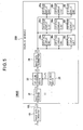
  • FIG. 5 is a schematic block diagram of the display apparatus 1000B in the second embodiment of the invention.
  • the display apparatus 1000B comprises a display module 20B and the above-described image data generator 10.
  • the display module 20B comprises first-stage display units 40a to 40i arranged in, for example, a matrix array, the above-described image data receiver 21, the above-described first color conversion means 22, the above-described first memory means 23, and the above-described image data transmitter 24.
  • Each of the nth-stage display units 50a to 50i (where n is an integer satisfying 1 ⁇ n ⁇ N - 1) comprises, as shown in FIG. 6, an image data receiver 41, an (n + 1)th color conversion means 42, an (n + 1)th memory means 43, and an image data transmitter 44.
  • n 1
  • display units 50a to 50i are the same as display units 40a to 40i.
  • the (n + 1)th color conversion means 42 receives the image data Dn, and also receives the display unit device numbers Io and the corresponding (n + 1)th luminance and chrominance conversion parameters Po, which are sent by the (n + 1)th memory means 43.
  • the (n + 1)th color conversion means 42 converts the luminance and chrominance of the image data Dn according to the (n + 1)th luminance and chrominance conversion parameters Po, and outputs the converted image data (also referred to as the '(n + 1)th color-converted image data') and the display unit device numbers Io to the image data transmitter 44.
  • the image data transmitter 44 sends the image data to the (n + 1)th-stage display units 60a to 60i designated by the display unit device numbers Io.
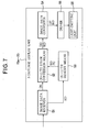
  • Each of the Nth-stage display units 70a to 70i comprises, as shown in FIG. 7, an image data receiver 51, an (N + 1)th color conversion means 52, an (N + 1)th memory means 53, an image data converter 54, a driver 55, and a light-emitting unit 56.
  • the image data receiver 51, (N + 1)th color conversion means 52, (N + 1)th memory means 53, image data converter 54, driver 55, and light-emitting unit 56 have substantially the same structure as the image data receiver 31, second color conversion means 32, second memory means 33, image data converter 34, driver 35, and light-emitting unit 36 in FIG. 2.
  • the (N + 1)th color conversion means 52 receives the image data DN and receives the pixel numbers KO of pixels in the light-emitting unit 56 and the corresponding (N + 1)th luminance and chrominance conversion parameters PO, which are sent by the (N + 1)th memory means 53.
  • the (N + 1)th color conversion means 52 converts the luminance and chrominance of the image data DN according to the (N + 1)th luminance and chrominance conversion parameters PO, and outputs the converted image data (also referred to as the '(N + 1)th color-converted image data') and the pixel numbers KO to the image data converter 54.
  • the image data converter 54 receives the image data DO and the pixel numbers KO of pixels in the light-emitting unit 56, converts the image data DO to driving signals DP suited for the light-emitting elements (in this case, LEDs) in the light-emitting unit 56, and outputs these signals and the pixel numbers KO of the pixels in the light-emitting unit 56.
  • the driver 55 drives the light-emitting elements in the light-emitting unit 56 corresponding to the pixel numbers KO of the pixels in the light-emitting unit 36 according to the driving signals DP.
  • the first color conversion means 22 shown in FIG. 5 performs luminance and chrominance conversions for the purpose of eliminating luminance and chrominance variations occurring between different display units 40a to 40i in the first stage; information including the parameters (first luminance and chrominance conversion parameters) P1 for the color conversion (luminance and chrominance conversion) performed by the first color conversion means 22 is stored in the first memory means 23.
  • the first color conversion parameters P1 are determined for each display unit on the basis of information about the display characteristics of the display units 40a to 40i for the purpose of eliminating luminance and chrominance variations occurring between different display units 40a to 40i in the first stage.
  • the (n + 1)th color conversion means 42 shown in FIG. 6 performs luminance and chrominance conversions for the purpose of eliminating luminance and chrominance variations occurring between different display units 60a to 60i in the (n + 1)th stage; information including the parameters (the (n + 1)th luminance and chrominance conversion parameters) Po for the color conversion (luminance and chrominance conversion) performed by the (n + 1)th color conversion means 42 is stored in the (n + 1)th memory means 43.
  • the (n + 1)th color conversion parameters Po are determined for each display unit on the basis of information about the display characteristics of the display units 60a to 60i in the (n + 1)th stage for the purpose of eliminating luminance and chrominance variations occurring between different display units 60a to 60i in the (n + 1)th stage.
  • the (N + 1)th color conversion means 52 shown in FIG. 7 performs luminance and chrominance conversions for the purpose of eliminating variations in luminance and chrominance occurring within each of the display units 70a to 70i in the Nth stage; information including the parameters (the (N + 1)th luminance and chrominance conversion parameters) PO for the color conversion (luminance and chrominance conversion) performed by the (N + 1)th color conversion means 52 is stored in the (N + 1)th memory means 53.
  • the (N + 1)th color conversion parameters PO are determined for each display unit on the basis of information about the color characteristics of its light-emitting elements for the purpose of eliminating luminance and chrominance variations occurring within the display units 70a to 70i in the Nth stage.
  • Image data DO expressed as a 3 ⁇ 1 matrix, are derived from image data DN, likewise expressed as a 3 ⁇ 1 matrix, by means of a 3 ⁇ 3 matrix H N+1 as shown in equation (5).
  • R N is the red signal value in image data DN
  • G N is the green signal value in image data DN
  • B N is the blue signal value in image data DN
  • R N+1 is the red signal value in image data DO
  • G N+1 is the green signal value in image data DO
  • B N+1 is the blue signal value in image data DO.
  • R N + 1 G N + 1 B N + 1 H N + 1 R N G N B N
  • the 3 ⁇ 3 matrix H N+1 is set as in equation (6).
  • X Rmeas , Y Rmeas , and Z Rmeas are measured tristimulus values when the maximum amount of light is emitted by a red light-emitting element in the light-emitting unit 56 and the amount of light emitted by the green and blue light-emitting elements is zero
  • X Gmeas , Y Gmeas , and Z Gmeas are measured tristimulus values when the maximum amount of light is emitted by a green light-emitting element in the light-emitting unit 56 and the amount of light emitted by the red and blue light-emitting elements is zero
  • X Bmeas , Y Bmeas , and Z Bmeas are measured tristimulus values when the maximum amount of light is emitted by a blue light-emitting element in the light-emitting unit 56 and the amount of light emitted by the red and
  • H N + 1 X Rmeas X Gmeas X Bmeas Y Rmeas Y Gmeas Y Bmeas Z Rmeas Z Gmeas Z Bmeas - 1 ⁇ X Rt arg et ⁇ N + 1 X Gt arg et ⁇ N + 1 X Bt arg et ⁇ N + 1 Y Rt arg et ⁇ N + 1 Y Gt arg et ⁇ N + 1 Y Bt arg et ⁇ N + 1 Z Rt arg et ⁇ N + 1 Z Gt arg et ⁇ N + 1 Z Bt arg et ⁇ N + 1
  • the values of X Rmeas , Y Rmeas , Z Rmeas , X Gmeas , Y Gmeas , Z Gmeas , X Bmeas , Y Bmeas , and Z Bmeas in equation (6) differ for each pixel number KO in the light-emitting unit 56.
  • the (N + 1)th luminance and chrominance conversion parameters PO therefore form a different matrix for each pixel number in the light-emitting unit 56, so it is necessary to switch the (N + 1)th luminance and chrominance conversion parameters PO for each pixel number KO in the light-emitting unit 56.
  • Image data D1 expressed as a 3 ⁇ 1 matrix, are derived from image data D, likewise expressed as a 3 ⁇ 1 matrix, by means of a 3 ⁇ 3 matrix H 1 as shown in equation (7).
  • R n is the red signal value in image data Dn
  • G n is the green signal value in image data Dn
  • B n is the blue signal value in image data Dn
  • R n+1 is the red signal value in image data Do
  • G n+1 is the green signal value in image
  • data Do and B n+1 is the blue signal value in image data Do.
  • R n + 1 G n + 1 B n + 1 H n + 1 R n G n B n
  • the 3 ⁇ 3 matrix H n+1 is set as in equation (8).
  • X Rtargetn+2 , Y Rtargetn+2 , and Z Rtargetn+2 are the tristimulus values of the target red color in the display units 60a to 60i in the (n + 1)th stage
  • X Gtargetn+2 , Y Gtargetn+2 , and Z Gtargetn+2 are the tristimulus values of the target green color in the display units 60a to 60i in the (n + 1)th stage
  • X Btargetn+2 , Y Btargetn+2 , and Z Btargetn+2 are the tristimulus values of the target blue color in the display units 60a to 60i in the (n + 1)th stage
  • X Rtargetn+1 , Y Rtargetn+1 , and Z Rtargetn+1 are the tristimulus values of the target red color spanning the display units 60a to 60i in the (n + 1) th stage
  • H N + 1 X Rt arg et ⁇ n + 2 X Gt arg et ⁇ n + 2 X Bt arg et ⁇ n + 2 Y Rt arg et ⁇ n + 2 Y Gt arg et ⁇ n + 2 Y Bt arg et ⁇ n + 2 Z Rt arg et ⁇ n + 2 Z Gt arg et ⁇ n + 2 Z Bt arg et ⁇ n + 2 - 1 ⁇ X Rt arg et ⁇ n + 1 X Gt arg et ⁇ n + 1 X Bt arg et ⁇ n + 1 Y Rt arg et ⁇ n + 1 Y Gt arg et ⁇ n + 1 Y Bt arg et ⁇ n + 1 Z Rt arg et ⁇ n + 1 Z Gt arg et
  • the 3 ⁇ 3 matrix H n+1 therefore incorporates the tristimulus values of the target colors within the display units 60a to 60i in the (n + 1)th stage and the target colors spanning the display units 60a to 60i in the (n + 1)th stage as shown in equation (8).
  • the values of X Rtargetn+2 , Y Rtargetn+2 , Z Rtargetn+2 , X Gtargetn+2 , Y Gtargetn+2 , Z Gtargetn+2 , X Btargetn+2 , Y Btargetn+2 , and Z Btargetn+2 in equation (8) differ for each display unit 60a to 60i in the (n + 1)th stage.
  • the (n + 1) luminance and chrominance conversion parameters Po therefore form a different matrix for each of the display units 60a to 60i in the (n + 1)th stage, making it necessary to switch the (n + 1)th luminance and chrominance conversion parameters Po for each of the (n + 1)th-stage display units 60a to 60i.
  • the display apparatus in the second embodiment provides a first color conversion means to convert luminance and chrominance for the display module as described above, and provides further color conversion means to convert luminance and chrominance for the display units in each of the multiple stages present in the display module, when a display unit in the nth stage is replaced, the chromaticity of the display apparatus can be readjusted just by rewriting the nth luminance and chrominance conversion parameters and the luminance and chrominance conversion parameters provided in the replaced nth-stage display unit.
  • the second color conversion means 32 provided in the display units 30a to 30i in the display apparatus 1000 in the first embodiment performed a luminance and chrominance conversion, but second color conversion means 37 that perform a luminance conversion without performing a chrominance conversion may be provided instead.
  • FIG. 8 is a schematic block diagram of the display apparatus 1000C in the third embodiment of the invention.
  • the display apparatus 1000C comprises a display module 20C and the above-described image data generator 10.
  • the display module 20C comprises display units 80a to 80i arranged in, for example, a matrix array, the above-described image data receiver 21, the above-described first color conversion means 22, the above-described first memory means 23, and the above-described image data transmitter 24.
  • Each of the display units 80a to 80i is structured as shown in FIG. 9.
  • the display unit shown in the drawing is similar to the display units (30a to 30i) shown in FIG. 2, but has a second color conversion means 37 in place of the second color conversion means 32.
  • the first color conversion means 22 shown in FIG. 8 performs luminance and chrominance conversions for the purpose of eliminating luminance and chrominance variations occurring between different display units 80a to 80i; information including the parameters (first luminance and chrominance conversion parameters) P3 for the color conversion (luminance and chrominance conversion) performed by the first color conversion means 22 is stored in the first memory means 23.
  • the first color conversion parameters P3 are determined for each display unit on the basis of information about the display characteristics of the display units 80a to 80i for the purpose of eliminating luminance and chrominance variations occurring between different display units 80a to 80i.
  • the second color conversion means 37 shown in FIG. 9 performs only luminance conversions for the purpose of eliminating variations in luminance occurring within each of the display units 80a to 80i; information including the parameters (second luminance conversion parameters) P4 for the color conversion (luminance conversion) performed by the second color conversion means 37 is stored in the second memory means 33.
  • the second luminance conversion parameters P4 are determined for each display unit on the basis of information about the color characteristics of its light-emitting elements for the purpose of eliminating luminance variations occurring within the display units 80a to 80i.
  • the image data receiver 31 in the one of the display units 80a to 80i that corresponds to the display unit device number I1 receives the image data D1, passes the data to the second color conversion means 37, and sends the second memory means 33 pixel numbers K4, which are generated in the image data receiver 31 and designate pixels in the light-emitting unit 36.
  • the second color conversion means 37 receives the image data D1, and receives the pixel number K4 of the pixels in the light-emitting unit 36 and the corresponding second luminance conversion parameters P4, which are sent by the second memory means 33.
  • the second color conversion means 37 converts the luminance of the image data D1 according to the second luminance conversion parameters P4, and outputs the converted image data (also referred to as the 'second color-converted image data') D4 and the pixel numbers K4 of pixels in the light-emitting unit 36.
  • the image data converter 34 receives the image data D4 and the pixel numbers K4 of pixels in the light-emitting unit 36, converts the image data D4 to driving signals D5 suited for the light-emitting elements (in this case, LEDs) in the light-emitting unit 36, and outputs these signals and the pixel numbers K4 of the pixels in the light-emitting unit 36.
  • the driver 35 drives the light-emitting elements in the light-emitting unit 36 corresponding to the pixel numbers K4 of the pixels in the light-emitting unit 36 according to the driving signals D5.
  • the second luminance conversion parameters P4 include the target luminance value of the image data D4 at the time of output to the display units 80a to 80i.
  • the second luminance conversion parameters P4 stored in the second memory means 33 are organized so as to be switchable according to the pixel numbers K2 of the pixels in the light-emitting unit 36.
  • a second color conversion means 37 is provided in each of the display units 80a to 80i as described above, when one of the display units 80a to 80i is replaced, it is possible to readjust the chromaticity of the display apparatus 1000C just by rewriting the first luminance and chrominance conversion parameters P1 and the second luminance conversion parameters P4 provided in the replaced display unit (one of 80a to 80i).
  • Image data D4 expressed as a 3 ⁇ 1 matrix, are derived from image data D1, likewise expressed as a 3 ⁇ 1 matrix, by means of a 3 ⁇ 3 matrix H 4 as shown in equation (9).
  • R 1 is the red signal value in image data D1
  • G 1 is the green signal value in image data D1
  • B 1 is the blue signal value in image data D1
  • R 4 is the red signal value in image data D4
  • G 4 is the green signal value in image data D4
  • B 4 is the blue signal value in image data D4.
  • R 4 G 4 B 4 H 4 R 1 G 1 B 1
  • the 3 ⁇ 3 matrix H 4 is set as in equation (10).
  • Y Rmeas is the measured luminance when the maximum amount of light is emitted by a red light-emitting element in the light-emitting unit 36 and the amount of light emitted by the green and blue light-emitting elements is zero
  • Y Gmeas is the measured luminance when the maximum amount of light is emitted by a green light-emitting element in the light-emitting unit 36 and the amount of light emitted by the red and blue light-emitting elements is zero
  • Y Bmeas is the measured luminance when the maximum amount of light is emitted by a blue light-emitting element in the light-emitting unit 36 and the amount of light emitted by the red and green light-emitting elements is zero
  • Y Rtarget4 is the luminance of the target red color in the display units 80a to 80i
  • Y Gtarget4 is the luminance of the target green color in the display units 80a to 80i
  • H 4 Y Rt arg et ⁇ 4 Y Rmeas 0 0 0 Y Gt arg et ⁇ 4 Y Gmeas 0 0 0 Y Bt arg et ⁇ 4 Y Bmeas
  • the values of Y Rmeas , Y Gmeas , and Y Bmeas in equation (10) differ for each pixel number K4 in the light-emitting unit 36.
  • the second luminance conversion parameters P4 therefore form a different matrix for each pixel number in the light-emitting unit 36, so it is necessary to switch the second luminance conversion parameters P4 for each pixel number K4 in the light-emitting unit 36.
  • the values of Y Rtarget4 , Y Rtarget4 , and Y Rtarget4 can be set to the minimum of the values Y Rmeas , Y Rmeas , and Y Rmeas of all the light-emitting elements in the light-emitting unit 36.
  • Image data D1 expressed as a 3 ⁇ 1 matrix, are derived from image data D, likewise expressed as a 3 ⁇ 1 matrix, by means of a 3 ⁇ 3 matrix H 3 as shown in equation (11).
  • R 0 is the red signal value in image data D
  • G 0 is the green signal value in image data D
  • B 0 is the blue signal value in image data D
  • R 1 is the red signal value in image data D1
  • G 1 is the green signal value in image data D1
  • B 1 is the blue signal value in image data D1.
  • R 1 G 1 B 1 H 3 R 0 G 0 B 0
  • the 3 ⁇ 3 matrix H 3 is set as in equation (12).
  • X Rtarget4 , Y Rtarget4 , and Z Rtarget4 are the tristimulus values of the target red color in the display units 80a to 80i
  • X Gtarget4 , Y Gtarget4 , and Z Gtarget4 are the tristimulus values of the target green color in the display units 80a to 80i
  • X Btarget4 , Y Btarget4 , and Z Btarget4 are the tristimulus values of the target blue color in the display units 80a to 80i
  • X Rtarget1 , Y Rtarget1 , and Z Rtarget1 are the tristimulus values of the target red color spanning the display units 80a to 80i
  • X Gtarget1 , Y Gtarget1 , and Z Gtarget1 are the tristimulus values of the target green color spanning the display units 80a to 80i
  • X Btarget1 , Y Btarget1 , and Z Btarget1 are
  • H 3 X Rt arg et 4 X Gt arg et 4 X Bt arg et 4 Y Rt arg et 4 Y Gt arg et 4 Y Bt arg et 4 Z Rt arg et 4 Z Gt arg et 4 Z Bt arg et 4 - 1 X Rt arg et ⁇ 1 X Gt arg et ⁇ 1 X Bt arg et ⁇ 1 Y Rt arg et ⁇ 1 Y Gt arg et ⁇ 1 Y Bt arg et ⁇ 1 Z Rt arg et ⁇ 1 Z Gt arg et ⁇ 1 Z Bt arg et ⁇ 1 Z Bt arg et ⁇ 1 Z Bt arg et ⁇ 1 Z Gt arg et ⁇ 1 Z Bt arg et ⁇ 1 Z Bt arg et ⁇ 1 Z G
  • the 3 ⁇ 3 matrix H 3 therefore incorporates the tristimulus values of the target colors within the display units 80a to 80i and the target colors spanning the display units 80a to 80i as shown in equation (12).
  • the values of X Rtarget4 , Y Rtarget4 , Z Rtarget4 , X Gtarget4 , Y Gtarget4 , Z Gtarget4 , X Btarget4 , Y Btarget4 , and Z Btarget4 in equation (12) differ for each display unit 80a to 80i.
  • the first luminance and chrominance conversion parameters P3 therefore form a different matrix for each display unit 80a to 80i, making it necessary to switch the first luminance and chrominance conversion parameters P3 for each display unit 80a to 80i.
  • the tristimulus values of the target colors in the display units 80a to 80i can be set by, for example, the method described below.
  • the minimum Y Rmeas , Y Rmeas , and Y Rmeas values of all the light-emitting elements in the light-emitting unit 36 are set as the values of Y Rtarget4 , Y Rtarget4 , and Y Rtarget4 , as explained above.
  • the mean chrominance values x Rmeas , y Rmeas measured when the red light-emitting elements in the light-emitting unit 36 emit the maximum amount of light and the amount of light emitted by the green and blue light-emitting elements is zero are set as the chrominance values x Rtarget4 , y Rtarget4 of the target red color in the display units 80a to 80i.
  • the mean chrominance values x Gmeas , y Gmeas measured when the green light-emitting elements in the light-emitting unit 36 emit the maximum amount of light and the amount of light emitted by the red and blue light-emitting elements is zero are set as the chrominance values x Gtarget4 , y Gtarget4 of the target green color in the display units 80a to 80i.
  • the mean chrominance values x Bmeas , y Bmeas measured when the blue light-emitting elements in the light-emitting unit 36 emit the maximum amount of light and the amount of light emitted by the red and green light-emitting elements is zero are set as the chrominance values x Btarget4 , y Btarget4 of the target blue color in the display units 80a to 80i.
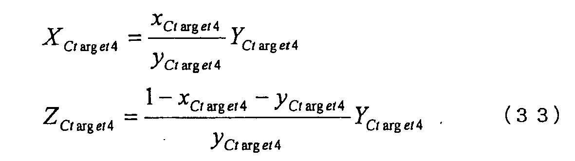
  • X Rtarget4 , Z Rtarget4 , X Gtarget4 , Z Gtarget4 , X Btarget4 , and Z Btarget4 are derived from equation (13).
  • X Ct arg et 4 x Ct arg et 4 y Ct arg et 4 ⁇ Y Ct arg et 4
  • Providing a first color conversion means 22 for the display module 20C and providing second color conversion means 37 in the display units 80a to 80i enables the luminance and chrominance of the entire display module 20C to be adjusted and enables an image with uniform chromaticity over the entire display apparatus 1000C to be obtained.
  • Providing a second color conversion means 37 in each display unit 80a to 80i enables the chromaticity of the display apparatus 1000C to be readjusted when one of the display units 80a to 80i (e.g., 80a) is replaced just by rewriting the first luminance and chrominance conversion parameters P1 and the second luminance conversion parameters P4 provided in the replaced display unit (80a).
  • the display module 20C comprises a plurality of display units 80a to 80i
  • the luminance and chrominance of the entire display module 20C can be easily adjusted.
  • the display apparatus in the third embodiment as described above provides a first color conversion means to convert luminance and chrominance for the display module, and provides a second color conversion means to convert the luminance within a display unit, when one of the display units is replaced, the chromaticity of the display apparatus can be readjusted just by rewriting the first luminance and chrominance conversion parameters and the second luminance conversion parameters provided in the replaced display unit.
  • FIG. 10 is a schematic block diagram of the display apparatus 1000D in the fourth embodiment of the invention.
  • the display apparatus 1000D comprises a display module 20D and the above-described image data generator 10.
  • the display module 20D comprises first-stage display units 90a to 90i arranged in, for example, a matrix array, the above-described image data receiver 21, the above-described first color conversion means 22, the above-described first memory means 23, and the above-described image data transmitter 24.
  • Each of the nth-stage display units 100a to 100i (where n is an integer satisfying 1 ⁇ n ⁇ N - 1) comprises, as shown in FIG. 11, the display units 110a to 110i arranged in a matrix array, for example, in the (n + 1)th stage, an image data receiver 41, an (n + 1)th color conversion means 47, an (n + 1)th memory means 43, and an image data transmitter 44.
  • display units 100a to 100i are the same as display units 90a to 90i.
  • the (n + 1)th color conversion means 47 receives the image data Dn', and also receives the display unit device numbers Io' and the corresponding (n + 1)th luminance conversion parameters Po', which are sent by the (n + 1)th memory means 43.
  • the (n + 1)th color conversion means 47 converts the luminance of the image data Dn according to the (n + 1)th luminance conversion parameters Po', and outputs the converted image data (also referred to as the '(n + 1)th color-converted image data') and the display unit device numbers Io', to the image data transmitter 44.
  • the image data transmitter 44 sends the image data to the (n + 1)th-stage display units 110a to 110i designated by the display unit device numbers Io'.
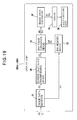
  • Each of the Nth-stage display units 120a to 120i comprises, as shown in FIG. 12, an image data receiver 51, an (N + 1)th color conversion means 57, an (N + 1)th memory means 53, an image data converter 54, a driver 55, and a light-emitting unit 56.
  • the image data receiver 51, the (N + 1)th color conversion means 52, the (N + 1)th memory means 53, image data converter 54, driver 55, and light-emitting unit 56 have substantially the same structure as the image data receiver 31, the second color conversion means 32, the second memory means 33, image data converter 34, driver 35, and light-emitting unit 36 in FIG. 2.
  • the (N + 1)th color conversion means 57 receives the image data DN' and receives the pixel numbers KO' of pixels in the light-emitting unit 56 and the corresponding (N + 1)th luminance conversion parameters PO', which are sent by the (N + 1)th memory means 53.
  • the (N + 1)th color conversion means 57 converts the luminance of the image data DN' according to the (N + 1)th luminance conversion parameters PO', and outputs the converted image data (also referred to as the '(N + 1)th color-converted image data') and the pixel numbers KO' to the image data converter 54.
  • the image data converter 54 receives the image data DO' and the pixel numbers KO' of pixels in the light-emitting unit 56, converts the image data DO' to driving signals DP' suited for the light-emitting elements (in this case, LEDs) in the light-emitting unit 56, and outputs these signals and the pixel numbers KO' of the pixels in the light-emitting unit 56.
  • driving signals DP' suited for the light-emitting elements (in this case, LEDs) in the light-emitting unit 56.
  • the driver 55 drives the light-emitting elements in the light-emitting unit 56 corresponding to the pixel numbers KO' of the pixels in the light-emitting unit 36 according to the driving signals DP'.
  • the first color conversion means 22 shown in FIG. 10 performs luminance and chrominance conversions for the purpose of eliminating luminance and chrominance variations occurring between different display units 90a to 90i in the first stage; information including the parameters (first luminance and chrominance conversion parameters) P3 for the color conversion (luminance and chrominance conversion) performed by the first color conversion means 22 is stored in the first memory means 23.
  • the first color conversion parameters P3 are determined for each display unit on the basis of,information about the display characteristics of the display units 90a to 90i for the purpose of eliminating luminance and chrominance variations occurring between different display units 90a to 90i in the first stage.
  • the (n + 1)th color conversion means 47 shown in FIG. 11 performs luminance conversions for the purpose of eliminating luminance variations occurring between different (n + 1)th-stage display units 110a to 110i; information including the parameters (the (n + 1)th luminance conversion parameters) Po' for the color conversion (luminance conversion) performed by the (n + 1)th color conversion means 47 is stored in the (n + 1)th memory means 43.
  • the (n + 1)th color conversion parameters Po' are determined for each display unit on the basis of information about the display characteristics of the (n + 1)th-stage display units 110a to 110i for the purpose of eliminating luminance variations occurring between different (n + 1)th-stage display units 110a to 110i.
  • the (N + 1)th color conversion means 57 shown in FIG. 12 performs luminance conversions for the purpose of eliminating variations in luminance occurring within each of the display units 120a to 120i in the Nth stage; information including the parameters (the (N + 1)th luminance conversion parameters) PO' for the color conversion (luminance conversion) performed by the (N + 1)th color conversion means 57 is stored in the (N + 1)th memory means 53.
  • the (N + 1)th luminance conversion parameters PO' are determined for each display unit on the basis of information about the color characteristics of its light-emitting elements for the purpose of eliminating luminance variations occurring within the display units 120a to 120i.
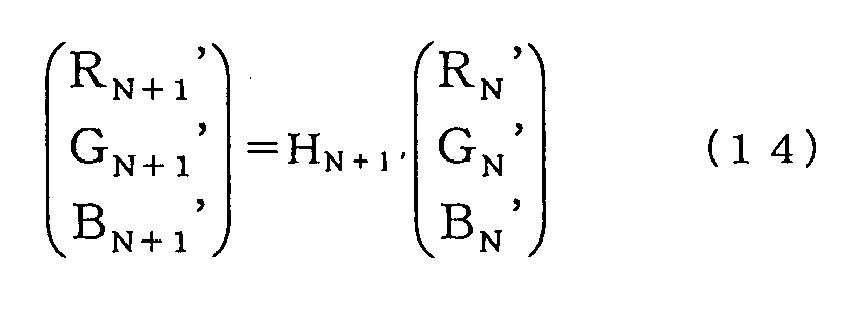
  • Image data DO' expressed as a 3 ⁇ 1 matrix, are derived from image data DN', likewise expressed as a 3 ⁇ 1 matrix, by means of a 3 ⁇ 3 matrix H N+1' as shown in equation (14).
  • R N' is the red signal value in image data DN'
  • G N' is the green signal value in image data DN'
  • B N' is the blue signal value in image data DN'
  • R N+1' is the red signal value in image data DO'
  • G N+1' is the green signal value in image data DO'
  • B N+1' is the blue signal value in image data DO'.
  • R N + 1 ⁇ ⁇ G N + 1 ⁇ ⁇ B N + 1 ⁇ ⁇ H N + 1 ⁇ ⁇ R N ⁇ ⁇ G N ⁇ ⁇ B N ⁇ ⁇
  • the 3 ⁇ 3 matrix H N+1' is set as in equation (15).
  • Y Rmeas is the measured luminance when the maximum amount of light is emitted by a red light-emitting element in the light-emitting unit 56 and the amount of light emitted by the green and blue light-emitting elements is zero
  • Y Gmeas is the measured luminance when the maximum amount of light is emitted by a green light-emitting element in the light-emitting unit 56 and the amount of light emitted by the red and blue light-emitting elements is zero
  • Y Bmeas is the measured luminance when the maximum amount of light is emitted by a blue light-emitting element in the light-emitting unit 56 and the amount of light emitted by the red and green light-emitting elements is zero
  • Y RtargetN+1' is the luminance of the target red color in the display units 120a to 120i in the Nth stage
  • Y GtargetN+1' is the luminance of the target
  • the values of Y Rmeas , Y Gmeas , and Y Bmeas in equation (15) differ for each pixel number KO' in the light-emitting unit 56.
  • the (N + 1)th luminance conversion parameters PO' therefore form a different matrix for each pixel number KO' in the light-emitting unit 56, so it is necessary to switch the (N + 1)th luminance conversion parameters PO' for each pixel number KO' in the light-emitting unit 56.
  • Image data Do' expressed as a 3 ⁇ 1 matrix, are derived from image data Dn', likewise expressed as a 3 ⁇ 1 matrix, by means of a 3 ⁇ 3 matrix H n+1' as shown in equation (16).
  • R n' is the red signal value in image data Dn'
  • G n' is the green signal value in image data Dn'
  • B n' is the blue signal value in image data Dn'
  • R n+1' is the red signal value in image data Do'
  • G n+1' is the green signal value in image data Do'
  • B n+1' is the blue signal value in image data Do'.
  • R n + 1 ⁇ ⁇ G n + 1 ⁇ ⁇ B n + 1 ⁇ ⁇ H n + 1 ⁇ ⁇ R n ⁇ ⁇ G n ⁇ ⁇ B n ⁇ ⁇
  • the 3 ⁇ 3 matrix H n+1' is set as in equation (17).
  • Y Rtargetn+2' is the luminance of the target red color in the display units 110a to 110i in the (n + 1)th stage
  • Y Gtargetn+2' is the luminance of the target green color in the display units 110a to 110i in the (n + 1)th stage
  • Y Btargetn+2' is the luminance of the target blue color in the display units 110a to 110i in the (n + 1)th stage
  • Y Rtargetn+1' is the luminance of the target red color spanning the display units 110a to 110i in the (n + 1)th stage
  • Y Gtargetn+1' is the luminance of the target green color spanning the display units 110a to 110i in the (n + 1)th stage
  • Y Btargetn+1' is the luminance of the target blue color spanning the display units 110a to 110i in the (n + 1)th stage.
  • the 3 ⁇ 3 matrix H n+1' therefore incorporates the tristimulus values of the target colors within the display units 110a to 110i in the (n + 1)th stage and the target colors spanning the display units 110a to 110i in the (n + 1)th stage as shown in equation (17).
  • the values of Y Rtargetn+2 , Y Gtargetn+2 and Y Btargetn+2 in equation (17) differ for each of the display units 110a to 110i in the (n + 1)th stage.
  • the (n + 1)th luminance conversion parameters Po' therefore form a different matrix for each display unit 110a to 110i, making it necessary to switch the (n + 1) luminance conversion parameters Po' for each of the (n + 1)th-stage display units 110a to 110i.
  • the display apparatus in the fourth embodiment provides a first color conversion means to convert luminance and chrominance for the display module as described above, and provides further color conversion means to convert luminance and chrominance for the display units in each of the multiple stages present in the display module, when a display unit in the nth stage is replaced, the chromaticity of the display apparatus can be readjusted just by rewriting the nth luminance conversion parameters and the luminance conversion parameters provided in the replaced nth-stage display unit.
  • FIG. 13 is a schematic block diagram of the display apparatus 2000 in a fifth embodiment of the invention.
  • the display apparatus 2000 shown in FIG. 13 comprises a display module 220 and an image data generator 10 disposed external to the display module 220.
  • the display module 220 comprises display units 230a to 230i arranged in, for example, a matrix array, an image data receiver 21 disposed external to the display units 230a to 230i, a first color conversion means 22, a first memory means 23, a gray-scale transforming means 25 and an image data transmitter 24.
  • display units 230a to 230i there are nine display units 230a to 230i arranged in a three-by-three matrix, but the number of rows and the number of columns may differ from three, and the number of rows may differ from the number of columns.
  • Each of the display units 230a to 230i has the same structure, comprising, as shown in FIG. 14, an image data receiver 31, an inverse gray-scale transforming means 38, a second color conversion means 32, a second memory means 33, an image data converter 34, a driver 35, and a light-emitting unit 36.
  • the light-emitting unit 36 has the same structure as described in the first embodiment.
  • the first color conversion means 22 shown in FIG. 13 performs luminance and chrominance conversions for the purpose of eliminating luminance and chrominance variations occurring between different display units 230a to 230i; information including the parameters (first luminance and chrominance conversion parameters) P1 for the color conversion (luminance and chrominance conversion) performed by the first color conversion means 22 is stored in the first memory means 23.
  • the first color conversion parameters P1 are determined for each display unit on the basis of information about the display characteristics of the display units 230a to 230i for the purpose of eliminating luminance and chrominance variations occurring between different display units 230a to 230i.
  • the second color conversion means 32 shown in FIG. 14 performs luminance and chrominance conversions for the purpose of eliminating variations in luminance and chrominance occurring within each of the display units 230a to 230i; information including the parameters (second luminance and chrominance conversion parameters) P2 for the color conversion (luminance and chrominance conversion) performed by the second color conversion means 32 is stored in the second memory means 33.
  • the second color conversion parameters P2 are determined for each display unit on the basis of information about the color characteristics of its light-emitting elements for the purpose of eliminating luminance and chrominance variations occurring within the display units 230a to 230i.
  • the image data receiver 21 receives image data E supplied through a transmission line 10L from the image data generator 10, passes the data to the first color conversion means 22, and sends display unit device numbers I1, which are generated in the image data receiver 21, to the first memory means 23.
  • the first color conversion means 22 receives the image data E with linear luminance, and also receives the display unit device numbers I1 and the corresponding first luminance and chrominance conversion parameters P1, which are sent by the first memory means 23.
  • the first color conversion means 22 converts the luminance and chrominance of the image data E according to the first luminance and chrominance conversion parameters P1, and outputs the converted image data (also referred to as the 'first color-converted image data') E1 and the display unit device numbers I1 to the gray-scale transforming means 25.
  • the gray-scale transforming means 25 transforms the gray-scale characteristic of the image data E1, and outputs the gray-scale-transformed image data (also referred to as the 'first gray-scale-transformed image data') and the display unit device numbers to the image data transmitter 24.
  • the image data transmitter 24 sends the gray-scale converted image data E2 to one of the display units 230a to 230i designated by the display unit device numbers I1.
  • Conversion of the image data E to image data E1 by use of the first luminance and chrominance conversion parameters P1 makes it possible to eliminate luminance and chrominance variations between different display units 230a to 230i that were present when the image data E were output to the display module 220.
  • the first luminance and chrominance conversion parameters P1 stored in the first memory means 23 are organized so as to be switchable according to the display unit device numbers I1.
  • the image data receiver 31 in the display unit (one of 230a to 230i) that corresponds to the device number I1 receives the image data E2, passes the data to the inverse gray-scale transforming means 38, and sends the second memory means 33 pixel numbers K2, which are generated in the image data receiver 31 and designate pixels in the light-emitting unit 36.
  • the inverse gray-scale transforming means 38 performs an inverse gray-scale transformation that undoes the gray-scale transformation to which the gray-scale-transformed image data E2 were subjected, thereby converting image data E2 to image data E3 with linear luminance, and outputs the image data E3 to the second color conversion means 32.
  • the second color conversion means 32 receives the image data E3, and receives the pixel numbers of the pixels in the light-emitting unit 36 and the corresponding second luminance and chrominance conversion parameters P2, which are sent by the second memory means 33.
  • the second color conversion means 32 converts the luminance and chrominance of the image data E3 according to the second luminance and chrominance conversion parameters P2, and outputs the converted image data (also referred to as the 'second color-converted image data') E4 and the pixel numbers K2 of pixels in the light-emitting unit 36.
  • the image data converter 34 receives the image data E4 and the pixel numbers K2 of pixels in the light-emitting unit 36, converts the image data E4 to driving signals E5 suited for the light-emitting elements (in this case, LEDs) in the light-emitting unit 36, and outputs these signals and the pixel numbers K2 of the pixels in the light-emitting unit 36.
  • the driver 35 drives the light-emitting elements in the light-emitting unit 36 corresponding to the pixel numbers K2 of the pixels in the light-emitting unit 36 according to the driving signals E5.
  • Conversion of image data E3 to image data E4 by use of the second luminance and chrominance conversion parameters P2 makes it possible to eliminate luminance and chrominance variations within the display units 230a to 230i that were present when the image data E3 were output to the display units 230a to 230i.
  • the second luminance and chrominance conversion parameters P2 stored in the second memory means 33 are organized so as to be switchable according to the pixel numbers K2 of the pixels in the light-emitting unit 36.
  • a second color conversion means 32 is provided in each of the display units 230a to 230i as described above, when one of the display units 230a to 230i is replaced, it is possible to readjust the chromaticity of the display apparatus 2000 just by rewriting the first luminance and chrominance conversion parameters P1 and the second luminance and chrominance conversion parameters P2 provided in the replaced display unit (one of 230a to 230i).
  • the image data generator 10 is structured as described in the first embodiment with reference to FIG. 4.
  • the image data output from the image data generator 10 has linear luminance.
  • Image data E1 expressed as a 3 ⁇ 1 matrix, are derived from image data E, likewise expressed as a 3 ⁇ 1 matrix, by means of a 3 ⁇ 3 matrix H 1 as shown in equation (18).
  • R 0 is the red signal value in image data E
  • G 0 is the green signal value in image data E
  • B 0 is the blue signal value in image data E
  • R 1 is the red signal value in image data E1
  • G 1 is the green signal value in image data E1
  • B 1 is the blue signal value in image data E1.
  • R 1 G 1 B 1 H 1 R 0 G 0 B 0
  • the 3 ⁇ 3 matrix H 1 is set as in equation (19).
  • X Rtarget2 , Y Rtarget2 , and Z Rtarget2 are the tristimulus values of the target red color in the display units 230a to 230i
  • X Gtarget2 , Y Gtarget2 , and Z Gtarget2 are the tristimulus values of the target green color in the display units 230a to 230i
  • X Btarget2 , Y Btarget2 , and Z Btarget2 are the tristimulus values of the target blue color in the display units 230a to 230i
  • X Rtarget1 , Y Rtarget1 , and Z Rtarget1 are the tristimulus values of the target red color spanning the display units 230a to 230i
  • X Gtarget1 , Y Gtarget1 , and Z Gtarget1 are the tristimulus values of the target green color spanning the display units 230a to 230i
  • the tristimulus values of the target colors within the display units 230a to 230i and the tristimulus values of the target colors spanning the display units 230a to 230i may be set to arbitrary values according to the characteristics of the light-emitting elements and the purpose for which the display apparatus will be used.
  • H 1 X Rt arg et ⁇ 2 X Gt arg et ⁇ 2 X Bt arg et ⁇ 2 Y Rt arg et ⁇ 2 Y Gt arg et ⁇ 2 Y Bt arg et ⁇ 2 Z Rt arg et ⁇ 2 Z Gt arg et ⁇ 2 Z Bt arg et ⁇ 2 - 1 X Rt arg et ⁇ 1 X Gt arg et ⁇ 1 X Bt arg et ⁇ 1 Y Rt arg et ⁇ 1 Y Gt arg et ⁇ 1 Y Bt arg et ⁇ 1 Z Rt arg et ⁇ 1 Z Gt arg et ⁇ 1 Z Bt arg et ⁇ 1 Z Bt arg et ⁇ 1 Z Gt arg et ⁇ 1 Z Bt arg et ⁇ 1 Z Bt arg
  • the 3 ⁇ 3 matrix H 1 therefore incorporates the tristimulus values of the target colors within the display units 230a to 230i and the target colors spanning the display units 230a to 230i as shown in equation (19).
  • the values of X Rtarget2 , Y Rtarget2 , Z Rtarget2 , X Gtarget2 , Y Gtarget2 , Z Gtarget2 , X Btarget2 , Y Btarget2 , and Z Btarget2 in equation (19) differ for each display unit 230a to 230i.
  • the first luminance and chrominance conversion parameters P1 therefore form a different matrix for each display unit 230a to 230i, making it necessary to switch the first luminance and chrominance conversion parameters P1 for each display unit 230a to 230i.
  • the gray-scale transforming means 25 transforms the image data E1, which have linear luminance, to image data E2 by the gray-scale transformation shown in equation (20).
  • C 1 is the red, green, or blue signal value in image data E1
  • C 2 is the red, green, or blue signal value in image data E2.
  • the quantity C MAX in equation (20) is the signal value in image data E1 when the light-emitting elements in the light-emitting unit 36 emit the maximum amount of light.
  • the inverse gray-scale transforming means 38 outputs image data E3 with linear luminance.
  • C 2 is the red, green, or blue signal value in image data E2
  • C 3 is the red, green, or blue signal value in image data E3.
  • the quantity C MAX in equation (21) is the signal value in image data E2 when the light-emitting elements in the light-emitting unit 36 emit the maximum amount of light.
  • Equation (21) narrows the spacing between adjacent signal values in the lower region of the signal values C 3 in image data E3, as compared with the lower region of the signal values C 2 in image data E2. This enables noise to be reduced when image data E2 are transferred from the image data transmitter 24 to the image data receiver 31.
  • image data E4 expressed as a 3 ⁇ 1 matrix
  • image data E3 are derived from image data E3, likewise expressed as a 3 ⁇ 1 matrix, by means of a 3 ⁇ 3 matrix H 2 as shown in equation (22).
  • R 3 is the red signal value in image data E3
  • G 3 is the green signal value in image data E3
  • B 3 is the blue signal value in image data E3
  • R 4 is the red signal value in image data E4
  • G 4 is the green signal value in image data E4
  • B 4 is the blue signal value in image data E4.
  • R 4 G 4 B 4 H 2 R 3 G 3 B 3
  • the 3 ⁇ 3 matrix H 2 is set as in equation (23).
  • X Rmeas , Y Rmeas , and Z Rmeas are measured tristimulus values when the maximum amount of light is emitted by a red light-emitting element in the light-emitting unit 36 and the amount of light emitted by the green and blue light-emitting elements is zero
  • X Gmeas , Y Gmeas , and Z Gmeas are measured tristimulus values when the maximum amount of light is emitted by a green light-emitting element in the light-emitting unit 36 and the amount of light emitted by the red and blue light-emitting elements is zero
  • X Bmeas , Y Bmeas , and Z Bmeas are measured tristimulus values when the maximum amount of light is emitted by a blue light-emitting element in the light-emitting unit 36 and the amount of light emitted by the red and green
  • H 2 X Rmeas X Gmeas X Bmeas Y Rmeas Y Gmeas Y Bmeas Z Rmeas Z Gmeas Z Bmeas - 1 X Rt arg et 2 X Gt arg et 2 X Bt arg et 2 Y Rt arg et 2 Y Gt arg et 2 Y Bt arg et 2 Z Rt arg et 2 Z Gt arg et 2 Z Bt arg et 2
  • the values Of X Rmeas , Y Rmeas , Z Rmeas , X Gmeas , Y Gmeas , Z Gmeas , X Bmeas , Y Bmeas , and Z Bmeas in equation (23) differ for each pixel number K2 in the light-emitting unit 36.
  • the second luminance and chrominance conversion parameters P2 therefore form a different matrix for each pixel number K2 in the light-emitting unit 36, so it is necessary to switch the second luminance and chrominance conversion parameters P2 for each pixel number K2 in the light-emitting unit 36.
  • Providing a first color conversion means 22 for the display module 220 and providing second color conversion means 32 in the display units 230a to 230i enables the luminance and chrominance of the entire display module 220 to be adjusted and enables an image with uniform chromaticity over the entire display apparatus 2000 to be obtained.
  • Providing a second color conversion means 32 in each display unit 230a to 230i enables the chromaticity of the display apparatus 2000 to be readjusted when one of the display units 230a to 230i is replaced just by rewriting the first luminance and chrominance conversion parameters P1 and the second luminance and chrominance conversion parameters P2 provided in the replaced display unit (one of 230a to 230i).
  • the display module 220 comprises a plurality of display units 230a to 230i
  • the luminance and chrominance of the entire display module 220 can be easily adjusted.
  • the transferred amount of image data E2 can be reduced without loss of image quality in the lower region of the signal values C 1 in image data E1.
  • Provision of the inverse gray-scale transforming means 38 before the second color conversion means 32 also enables noise to be reduced when image data E2 are transferred from the image data transmitter 24 to the image data receiver 31.
  • the display apparatus 2000 in the fifth embodiment there was one stage of display units 230a to 230i in the display module 220 and second color conversion means 32 were provided in the display units 230a to 230i, but there may be multiple stages of display units, and color conversion means may be provided for the display units in each stage.
  • a specific method will be described below under the assumption that there are N stages of display units (where N is an integer equal to or greater than two). The following description will focus on the differences from the display apparatus 2000 in FIG. 13; constituent elements equivalent to constituent elements that have already been described will have the same reference characters, and the previous descriptions will be referred to.
  • FIG. 15 is a schematic block diagram of the display apparatus 2000B in the sixth embodiment of the invention.
  • the display apparatus 2000B comprises a display module 220B and the above-described image data generator 10.
  • the display module 220B comprises the first stage display units 240a to 240i, which are arranged in, for example, a matrix array, the above-described image data receiver 21, the above-described first color conversion means 22, the above-described first memory means 23, a first gray-scale transforming means 25b, and the above-described image data transmitter 24.
  • Each of the nth-stage display units 250a to 250i (where n is an integer satisfying 1 ⁇ n ⁇ N - 1) comprises, as shown in FIG. 16, the display units 260a to 260i arranged in a matrix array, for example, in the (n + 1)th stage, an image data receiver 41, the nth inverse gray-scale transforming means 48, the (n + 1)th color conversion means 42, the (n + 1)th memory means 43, the (n + 1)th gray-scale transforming means 45, and an image data transmitter 44.
  • n 1, display units 250a to 250i are the same as display units 240a to 240i.
  • the nth inverse gray-scale transforming means 48 performs an inverse gray-scale transformation that undoes the gray-scale transformation to which the gray-scale-transformed image data Em were subjected, thereby converting image data Em to image data En with linear luminance, and outputs the image data En to the (n + 1)th color conversion means 42.
  • the (n + 1)th color conversion means 42 receives the image data En, and also receives the display unit device numbers Io and the corresponding (n + 1)th luminance and chrominance conversion parameters Po, which are sent by the (n + 1)th memory means 43.
  • the (n + 1)th color conversion means 42 converts the luminance and chrominance of the image data En according to the (n + 1)th luminance and chrominance conversion parameters Po, and outputs the converted image data (also referred to as the '(n + 1)th color-converted image data') and the display unit device numbers Io to the (n + 1)th gray-scale transforming means 45.
  • the (n + 1)th gray-scale transforming means 45 transforms the gray-scale characteristic of the image data Eo, and outputs the gray-scale-transformed image data (also referred to as the '(n + 1)th gray-scale-transformed image data') Ep and the display unit device numbers Io to the image data transmitter 44.
  • the image data transmitter 44 sends the image data to the (n + 1)th-stage display units 260a to 260i designated by the display unit device numbers Io.
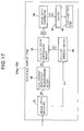
  • Each of the Nth-stage display units 270a to 270i comprises, as shown in FIG. 17, an image data receiver 51, an Nth inverse gray-scale transforming means 58, an (N + 1)th color conversion means 52, an (N + 1)th memory means 53, an image data converter 54, a driver 55, and a light-emitting unit 56.
  • the image data receiver 51, the Nth stage Nth inverse gray-scale transforming means 58, the (N + 1)th color conversion means 52, the (N + 1)th memory means 53, image data converter 54, driver 55, and light-emitting unit 56 have substantially the same structure as the image data receiver 31, inverse gray-scale transforming means 38, second color conversion means 32, second memory means 33, image data converter 34, driver 35, and light-emitting unit 36 in FIG. 2.
  • the Nth inverse gray-scale transforming means 58 performs an inverse gray-scale transformation that undoes the gray-scale transformation to which the gray-scale-transformed image data EM were subjected, thereby converting image data EM to image data EN with linear luminance, and outputs the image data EN to the (N + 1)th color conversion means 52.
  • the (N + 1)th color conversion means 52 receives the image data EN and receives the pixel numbers KO of pixels in the light-emitting unit 56 and the corresponding (N + 1)th luminance and chrominance conversion parameters PO, which are sent by the (N + 1)th memory means 53.
  • the (N + 1)th color conversion means 52 converts the luminance and chrominance of the image data EN according to the (N + 1)th luminance and chrominance conversion parameters PO, and outputs the converted image data (also referred to as the '(N + 1)th color-converted image data') and the pixel numbers KO to the image data converter 54.
  • the image data converter 54 receives the image data EO and the pixel numbers KO of pixels in the light-emitting unit 56, converts the image data EO to driving signals EP suited for the light-emitting elements (in this case, LEDs) in the light-emitting unit 56, and outputs these signals and the pixel numbers KO of the pixels in the light-emitting unit 56.
  • the driver 55 drives the light-emitting elements in the light-emitting unit 56 corresponding to the pixel numbers KO of the pixels in the light-emitting unit 56 according to the driving signals EP.
  • the display units in each stage from the first stage to the Nth stage are arranged in a three-by-three matrix, but the number of rows and the number of columns may each differ from three, and the numbers may differ in different stages.
  • the first color conversion means 22 shown in FIG. 15 performs luminance and chrominance conversions for the purpose of eliminating luminance and chrominance variations occurring between different display units 240a to 240i in the first stage; information including the parameters (first luminance and chrominance conversion parameters) P1 for the color conversion (luminance and chrominance conversion) performed by the first color conversion means 22 is stored in the first memory means 23.
  • the first color conversion parameters P1 are determined for each display unit on the basis of information about the display characteristics of the display units 240a to 240i for the purpose of eliminating luminance and chrominance variations occurring between different display units 240a to 240i in the first stage.
  • the (n + 1)th color conversion means 42 shown in FIG. 16 performs luminance and chrominance conversions for the purpose of eliminating luminance and chrominance variations occurring between different display units 260a to 260i in the (n + 1)th-stage; information including the parameters (the (n + 1)th luminance and chrominance conversion parameters) Po for the color conversion (luminance and chrominance conversion) performed by the (n + 1)th color conversion means 42 is stored in the (n + 1)th memory means 43.
  • the (n + 1)th color conversion parameters Po are determined for each display unit on the basis of information about the display characteristics of the display units 260a to 260i in the (n + 1)th stage for the purpose of eliminating luminance and chrominance variations occurring between different display units 260a to 260i in the (n + 1)th stage.
  • the (N + 1)th color conversion means 52 shown in FIG. 17 performs luminance and chrominance conversions for the purpose of eliminating variations in luminance and chrominance occurring within each of the display units 270a to 270i in the Nth stage; information including the parameters (the (N + 1)th luminance and chrominance conversion parameters) PO for the color conversion (luminance and chrominance conversion) performed by the (N + 1)th Nth inverse gray-scale transforming means 58 is stored in the (N + 1)th memory means 53.
  • the (N + 1)th color conversion parameters PO are determined for each display unit on the basis of information about the color characteristics of its light-emitting elements for the purpose of eliminating luminance and chrominance variations occurring within the display units 270a to 270i in the Nth stage.
  • the gray-scale transformation is performed in the first gray-scale transforming means 25b by the same method as in the gray-scale transforming means 25, which has already been described, so a description will be omitted here.
  • the nth inverse gray-scale transforming means 48 outputs image data En with linear luminance.
  • C m is the red, green, or blue signal value in image data Em
  • C n is the red, green, or blue signal value in image data En.
  • the quantity C MAX in equation (24) is the signal value in image data Em when the light-emitting elements in the light-emitting unit 36 emit the maximum amount of light.
  • Equation (24) narrows the spacing between adjacent signal values in the lower region of the signal values C n in image data En, as compared with the lower region of the signal values C m in image data Em. This enables noise to be reduced when image data Em are transferred to the image data receiver 41.
  • image data Eo expressed as a 3 ⁇ 1 matrix
  • image data En are derived from image data En, likewise expressed as a 3 ⁇ 1 matrix, by means of a 3 ⁇ 3 matrix H n+1 as shown in equation (25).
  • R n is the red signal value in image data En
  • G n is the green signal value in image data En
  • B n is the blue signal value in image data En
  • R n+1 is the red signal value in image data Eo
  • G n+1 is the green signal value in image data Eo
  • B n+1 is the blue signal value in image data Eo.
  • R n + 1 G n + 1 B n + 1 H N + 1 R n G n B n
  • the 3 ⁇ 3 matrix H n+1 is set as in equation (26).
  • X Rtargetn+2 , Y Rtargetn+2 , and Z Rtargetn+2 are the tristimulus values of the target red color in the display units 260a to 260i in the (n + 1)th stage
  • X Gtargetn+2 , Y Gtargetn+2 , and Z Gtargetn+2 are the tristimulus values of the target green color in the display units 260a to 260i in the (n + 1)th stage
  • X Btargetn+2 , Y Btargetn+2 , and Z Btargetn+2 are the tristimulus values of the target blue color in the display units 260a to 260i in the (n + 1)th stage
  • X Rtargetn+1 , Y Rtargetn+1 , and Z Rtargetn+1 are the tristimulus values of the target red color spanning the display units 260a to 260i in the (n + 1)th stage
  • H N + 1 X Rt arg et ⁇ n + 2 X Gt arg et ⁇ n + 2 X Bt arg et ⁇ n + 2 Y Rt arg et ⁇ n + 2 Y Gt arg et ⁇ n + 2 Y Bt arg et ⁇ n + 2 Z Rt arg et ⁇ n + 2 Z Gt arg et ⁇ n + 2 Z Bt arg et ⁇ n + 2 - 1 ⁇ X Rt arg et ⁇ n + 1 X Gt arg et ⁇ n + 1 X Bt arg et ⁇ n + 1 Y Rt arg et ⁇ n + 1 Y Gt arg et ⁇ n + 1 Y Bt arg et ⁇ n + 1 Z Rt arg et ⁇ n + 1 Z Gt arg et
  • the 3 ⁇ 3 matrix H n+1 therefore incorporates the tristimulus values of the target colors within the display units 260a to 260i in the (n + 1)th stage and the target colors spanning the display units 260a to 260i in the (n + 1)th stage as shown in equation (26).
  • the values of X Rtargetn+2 , Y Rtargetn+2 , Z Rtargetn+2 , X Gtargetn+2 , Y Gtargetn+2 , Z Gtargetn+2 , X Btargetn+2, Y Btargetn+2 , and Z Btargetn+2 in equation (26) differ for each of the display units 260a to 260i in the (n + 1)th stage.
  • the (n + 1)th luminance and chrominance conversion parameters Po therefore form a different matrix for each of the display units 260a to 260i, making it necessary to switch the (n + 1)th luminance and chrominance conversion parameters Po for each of the (n + 1)th-stage display units 260a to 260i.
  • the (n + 1)th gray-scale transforming means 45 transforms the image data Eo, which have linear luminance, to image data Ep by the gray-scale transformation shown in equation (27).
  • C o is the red, green, or blue signal value in image data Eo
  • C p is the red, green, or blue signal value in image data Ep.
  • the quantity C MAX in equation (27) is the signal value in image data Eo when the light-emitting elements in the light-emitting unit 56 emit the maximum amount of light.
  • C P C MAX ⁇ C o C MAX 1 ⁇
  • the Nth inverse gray-scale transforming means 58 outputs image data EN with linear luminance.
  • C M is the red, green, or blue signal value in image data EM
  • C N is the red, green, or blue signal value in image data EN.
  • the quantity C MAX in equation (28) is the signal value in image data EM when the light-emitting elements in the light-emitting unit 56 emit the maximum amount of light.
  • C N C MAX ⁇ C M C MAX ⁇
  • Equation (28) narrows the spacing between adjacent signal values in the lower region of the signal values C N in image data EN, as compared with the lower region of the signal values C M in image data EM. This enables noise to be reduced when image data EM are transferred to the image data receiver 51.
  • image data EO expressed as a 3 ⁇ 1 matrix
  • image data EN likewise expressed as a 3 ⁇ 1 matrix, by means of a 3 ⁇ 3 matrix H N+1 as shown in equation (29).
  • R N is the red signal value in image data EN
  • G N is the green signal value in image data EN
  • B N is the blue signal value in image data EN
  • R N+1 is the red signal value in image data EO
  • G N+1 is the green signal value in image data EO
  • B N+1 is the blue signal value in image data EO.
  • the 3 ⁇ 3 matrix H N+1 is set as in equation (30).
  • X Rmeas , Y Rmeas , and Z Rmeas are measured tristimulus values when the maximum amount of light is emitted by a red light-emitting element in the light-emitting unit 56 and the amount of light emitted by the green and blue light-emitting elements is zero
  • X Gmeas , Y Gmeas , and Z Gmeas are measured tristimulus values when the maximum amount of light is emitted by a green light-emitting element in the light-emitting unit 56 and the amount of light emitted by the red and blue light-emitting elements is zero
  • X Bmeas , Y Bmeas , and Z Bmeas are measured tristimulus values when the maximum amount of light is emitted by a blue light-emitting element in the light-emitting unit 56 and the amount of light emitted by the red and green
  • H N + 1 X Rmeas X Gmeas X Bmeas Y Rmeas Y Gmeas Y Bmeas Z Rmeas Z Gmeas Z Bmeas - 1 ⁇ X Rt arg et ⁇ N + 1 X Gt arg et ⁇ N + 1 X Bt arg et ⁇ N + 1 Y Rt arg et ⁇ N + 1 Y Gt arg et ⁇ N + 1 Y Bt arg et ⁇ N + 1 Z Rt arg et ⁇ N + 1 Z Gt arg et ⁇ N + 1 Z Bt arg et ⁇ N + 1
  • the values Of X Rmeas , Y Rmeas , Z Rmeas , X Gmeas , Y Gmeas , Z Gmeas , X Bmeas , Y Bmeas , and Z Bmeas in equation (30) differ for each pixel number KO in the light-emitting unit 56.
  • the (N + 1)th luminance and chrominance conversion parameters PO therefore form a different matrix for each pixel number in the light-emitting unit 56, so it is necessary to switch the (N + 1)th luminance and chrominance conversion parameters PO for each pixel number KO in the light-emitting unit 56.
  • Providing a first color conversion means 22 for the display module 220B, providing (n + 1)th color conversion means 42 in the display units 250a to 250i and providing (N + 1)th color conversion means 52 in the display units 270a to 270i enables the luminance and chrominance of the entire display module 220B to be adjusted and enables an image with uniform chromaticity over the entire display apparatus 2000B to be obtained.
  • Providing an (n + 1)th color conversion means 42 in each display unit 250a to 250i enables the chromaticity of the display apparatus 2000B to be readjusted when one of the display units 250a to 250i is replaced just by rewriting the nth luminance and conversion parameters provided in the display unit one stage before the replaced display unit (one of 250a to 250i), and rewriting the (n + 1)th luminance and chrominance conversion parameters Po provided in the replaced display unit (one of 250a to 250i).
  • the display module 220B comprises a plurality of display units 250a to 250i
  • the luminance and chrominance of the entire display module 220B can be easily adjusted.
  • the transferred amount of image data E2 and Ep can be reduced compared to that of image data E1, without loss of image quality in the lower region of the signal values C 1 in image data E1.
  • Provision of the nth inverse gray-scale transforming means 48 before the (n + 1)th color conversion means 42 also enables noise to be reduced when image data Em are transferred between display units.
  • the second color conversion means 32 provided in the display units 230a to 230i in the display apparatus 2000 in the fifth embodiment performed a luminance and chrominance conversion, but second color conversion means 37 that perform a luminance conversion without performing a chrominance conversion may be provided instead.
  • FIG. 18 is a schematic block diagram of the display apparatus 2000C in the seventh embodiment of the invention. As shown in FIG. 18, the display apparatus 2000C comprises a display module 220C and the above-described image data generator 10.
  • the display module 220C comprises display units 280a to 280i arranged in, for example, a matrix array, the above-described image data receiver 21, the above-described first color conversion means 22, the above-described first memory means 23, the above-described gray-scale transforming means 25 and the above-described image data transmitter 24.
  • Each of the display units 280a to 280i is structured as shown in FIG. 19.
  • the display unit shown in the drawing is similar to the display units (230a to 230i) shown in FIG. 14, but has a second color conversion means 37 in place of the second color conversion means 32.
  • the first color conversion means 22 shown in FIG. 18 performs luminance and chrominance conversions for the purpose of eliminating luminance and chrominance variations occurring between different display units 280a to 280i; information including the parameters (first luminance and chrominance conversion parameters) P3 for the color conversion (luminance and chrominance conversion) performed by the first color conversion means 22 is stored in the first memory means 23.
  • the first color conversion parameters P3 are determined for each display unit on the basis of information about the display characteristics of the display units 280a to 280i for the purpose of eliminating luminance and chrominance variations occurring between different display units 280a to 280i.
  • the second color conversion means 37 shown in FIG. 19 performs only luminance conversions for the purpose of eliminating variations in luminance occurring within each of the display units 280a to 280i; information including the parameters (second luminance conversion parameters) P4 for the color conversion (luminance conversion) performed by the second color conversion means 37 is stored in the second memory means 33.
  • the second luminance conversion parameters P4 are determined for each display unit on the basis of information about the color characteristics of its light-emitting elements for the purpose of eliminating luminance variations occurring within the display units 280a to 280i.
  • the image data receiver 31 in the one of the display units 280a to 280i that corresponds to the display unit device number I1 receives the image data E2, passes the data to the inverse gray-scale transforming means 38, and sends the second memory means 33 pixel numbers K4, which are generated in the image data receiver 31 and designate pixels in the light-emitting unit 36.
  • the inverse gray-scale transforming means 38 performs an inverse gray-scale transformation that undoes the gray-scale transformation to which the gray-scale-transformed image data E2 were subjected, thereby converting image data E2 to image data E3 with linear luminance, and outputs the image data E3 to the second color conversion means 37.
  • the second color conversion means 37 receives the image data E3, and receives the pixel number K4 of the pixel in the light-emitting unit 36 and the corresponding second luminance conversion parameters P4, which are sent by the second memory means 33.
  • the second color conversion means 37 converts the luminance of the image data E3 according to the second luminance conversion parameters P4, and outputs the converted image data E6 and the pixel numbers K4 of pixels in the light-emitting unit 36.
  • the image data converter 34 receives the image data E6 and the pixel numbers K4 of pixels in the light-emitting unit 36, converts the image data E6 to driving signals E7 suited for the light-emitting elements (in this case, LEDs) in the light-emitting unit 36, and outputs these signals and the pixel numbers K4 of the pixels in the light-emitting unit 36.
  • the driver 35 drives the light-emitting elements in the light-emitting unit 36 corresponding to the pixel numbers K4 of the pixels in the light-emitting unit 36 according to the driving signals E7.
  • the second luminance conversion parameters P4 include the target value of luminance of the image data E6 at the time of output to the display units 280a to 280i.
  • the second luminance conversion parameters P4 stored in the second memory means 33 are organized so as to be switchable according to the pixel numbers K2 of the pixels in the light-emitting unit 36.
  • a second color conversion means 37 is provided in each of the display units 280a to 280i as described above, when one of the display units 280a to 280i is replaced, it is possible to readjust the chromaticity of the display apparatus 2000C just by rewriting the first luminance and chrominance conversion parameters P1 and the second luminance conversion parameters P4 provided in the replaced display unit (one of 280a to 280i).
  • image data E1 expressed as a 3 ⁇ 1 matrix
  • image data E are derived from image data E, likewise expressed as a 3 ⁇ 1 matrix, by means of a 3 ⁇ 3 matrix H 3 as shown in equation (31).
  • R 0 is the red signal value in image data E
  • G 0 is the green signal value in image data E
  • B 0 is the blue signal value in image data E
  • R 1 is the red signal value in image data E1
  • G 1 is the green signal value in image data E1
  • B 1 is the blue signal value in image data E1.
  • R 1 G 1 B 1 H 3 R 0 G 0 B 0
  • the 3 ⁇ 3 matrix H 3 is set as in equation (32).
  • X Rtarget4 , Y Rtarget4 , and Z Rtarget4 are the tristimulus values of the target red color in the display units 280a to 280i
  • X Gtarget4 , Y Gtarget4 , and Z Gtarget4 are the tristimulus values of the target green color in the display units 280a to 280i
  • X Btarget4 , Y Btarget4 , and Z Btarget4 are the tristimulus values of the target blue color in the display units 280a to 280i
  • X Rtarget1 , Y Rtarget1 , and Z Rtarget1 are the tristimulus values of the target red color spanning the display units 280a to 280i
  • X Gtarget1 , Y Gtarget1 , and Z Gtarget1 are the tristimulus values of the target green color spanning the display units 280a to 280i
  • H 3 X Rt arg et 4 X Gt arg et 4 X Bt arg et 4 Y Rt arg et 4 Y Gt arg et 4 Y Bt arg et 4 Z Rt arg et 4 Z Gt arg et 4 Z Bt arg et 4 - 1 X Rt arg et ⁇ 1 X Gt arg et ⁇ 1 X Bt arg et ⁇ 1 Y Rt arg et ⁇ 1 Y Gt arg et ⁇ 1 Y Bt arg et ⁇ 1 Z Rt arg et ⁇ 1 Z Gt arg et ⁇ 1 Z Bt arg et ⁇ 1 Z Bt arg et ⁇ 1 Z Bt arg et ⁇ 1 Z Gt arg et ⁇ 1 Z Bt arg et ⁇ 1 Z Bt arg et ⁇ 1 Z G
  • the 3 ⁇ 3 matrix H 3 therefore incorporates the tristimulus values of the target colors within the display units 280a to 280i and the target colors spanning the display units 280a to 280i as shown in equation (32).
  • the values of X Rtarget4 , Y Rtarget4 , Z Rtarget4 , X Gtarget4 , Y Gtarget4 , Z Gtarget4 , X Btarget4 , Y Btarget4 , and Z Btarget4 in equation (32) differ for each display unit 280a to 280i.
  • the first luminance and chrominance conversion parameters P3 therefore form a different matrix for each display unit 280a to 280i, making it necessary to switch the first luminance and chrominance conversion parameters P3 for each display unit 280a to 280i.
  • the tristimulus values of the target colors in the display units 280a to 280i can be set by, for example, the method described below.
  • the minimum Y Rmeas , Y Gmeas , and Y Bmeas values of all the light-emitting elements in the light-emitting unit 36 are set as the values of Y Rtarget4 , Y Gtarget4 , and Y Btarget4 , as explained above.
  • the mean chrominance values x Rmeas , y Rmeas measured when the red light-emitting elements in the light-emitting unit 36 emit the maximum amount of light and the amount of light emitted by the green and blue light-emitting elements is zero are set as the chrominance values x Rtarget4 , Y Rtarget4 of the target red color in the display units 280a to 280i.
  • the mean chrominance values x Gmeas , y Gmeas measured when the green light-emitting elements in the light-emitting unit 36 emit the maximum amount of light and the amount of light emitted by the red and blue light-emitting elements is zero are set as the chrominance values x Gtarget4 , y Gtarget4 of the target green color in the display units 280a to 280i.
  • the mean chrominance values x Bmeas , Y Bmeas measured when the blue light-emitting elements in the light-emitting unit 36 emit the maximum amount of light and the amount of light emitted by the red and green light-emitting elements is zero are set as the chrominance values x Btarget4 , y Btarget4 of the target blue color in the display units 280a to 280i.
  • X Rtarget4 , Z Rtarget4 , X Gtarget4 , Z Gtarget4 , X Btarget4 , and Z Btarget4 are derived from equation (33).
  • X Ct arg et 4 x Ct arg et 4 y Ct arg et 4 ⁇ Y Ct arg et 4
  • image data E6, expressed as a 3 ⁇ 1 matrix are derived from image data E3, likewise expressed as a 3 ⁇ 1 matrix, by means of a 3 ⁇ 3 matrix H 4 as shown in equation (34).
  • R 3 is the red signal value in image data E3, G 3 is the green signal value in image data E3, and B 3 is the blue signal value in image data E3;
  • R 6 is the red signal value in image data E6, G 6 is the green signal value in image data E6, and B 6 is the blue signal value in image data E6.
  • R 6 G 6 B 6 H 4 R 3 G 3 B 3
  • the 3 ⁇ 3 matrix H 4 is set as in equation (35).
  • Y Rmeas is the measured luminance when the maximum amount of light is emitted by a red light-emitting element in the light-emitting unit 36 and the amount of light emitted by the green and blue light-emitting elements is zero
  • Y Gmeas is the measured luminance when the maximum amount of light is emitted by a green light-emitting element in the light-emitting unit 36 and the amount of light emitted by the red and blue light-emitting elements is zero
  • Y Bmeas is the measured luminance when the maximum amount of light is emitted by a blue light-emitting element in the light-emitting unit 36 and the amount of light emitted by the red and green light-emitting elements is zero
  • Y Rtarget4 is the luminance of the target red color in the display units 280a to 280i
  • Y Gtarget4 is the luminance of the target green color in the display units 280
  • H 4 Y Rt arg et ⁇ 4 Y Rmeas 0 0 0 Y Gt arg et ⁇ 4 Y Gmeas 0 0 0 Y Bt arg et ⁇ 4 Y Bmeas
  • the values of Y Rmeas , Y Gmeas , and Y Bmeas in equation (35) differ for each pixel number K4 in the light-emitting unit 36.
  • the second luminance conversion parameters P4 therefore form a different matrix for each pixel number in the light-emitting unit 36, so it is necessary to switch the second luminance conversion parameters P4 for each pixel number K4 in the light-emitting unit 36.
  • the values of Y Rtarget4 , Y Rtarget4 , and Y Rtarget4 can be set to the minimum of the values Y Rmeas , Y Rmeas , and Y Rmeas of all the light-emitting elements in the light-emitting unit 36.
  • Providing a first color conversion means 22 for the display module 220C and providing second color conversion means 37 in the display units 280a to 280i enables the luminance and chrominance of the entire display module 220C to be adjusted and enables an image with uniform chromaticity over the entire display apparatus 2000C to be obtained.
  • Providing a second color conversion means 37 in each display unit 280a to 280i enables the chromaticity of the display apparatus 2000C to be readjusted when one of the display units 280a to 280i is replaced just by rewriting the first luminance and chrominance conversion parameters P1 and the second luminance conversion parameters P4 provided in the replaced display unit (one of 280a to 280i).
  • the display module 220C comprises a plurality of display units 280a to 280i
  • the luminance and chrominance of the entire display module 220C can be easily adjusted.
  • the transferred amount of image data E2 can be reduced compared with the image data E1, without loss of image quality in the lower region of the signal values C 1 in image data E1.
  • Provision of the inverse gray-scale transforming means 38 before the second color conversion means 37 also enables noise to be reduced when image data E2 are transferred from the image data transmitter 24 to the image data receiver 31.
  • the display apparatus 2000C in the seventh embodiment there was one stage of display units 280a to 280i in the display module 220C and second color conversion means 37 were provided in the display units 280a to 280i, but there may be multiple stages of display units, and color conversion means may be provided for the display units in each stage.
  • a specific method will be described below under the assumption that there are N stages of display units (where N is an integer equal to or greater than two).
  • FIG. 20 is a schematic block diagram of the display apparatus 2000D in the eighth embodiment of the invention.
  • the display apparatus 2000D comprises a display module 220D and the above-described image data generator 10.
  • the display module 220D comprises display units 290a to 290i arranged in, for example, a matrix array, the above-described image data receiver 21, the above-described first color conversion means 22, the above-described first memory means 23, the above-described first gray-scale transforming means 25b, and the above-described image data transmitter 24.
  • Each of the nth-stage display units 300a to 300i (where n is an integer satisfying 1 ⁇ n ⁇ N - 1) comprises, as shown in FIG. 21, the display units 310a to 310i arranged in a matrix array, for example, in the (n + 1)th stage, the above-described image data receiver 41, the above-described nth inverse gray-scale transforming means 48, an (n + 1)th color conversion means 47, the above-described (n + 1)th memory means 43, and the above-described image data transmitter 44.
  • n 1
  • display units 300a to 300i are the same as display units 290a to 290i.
  • the nth inverse gray-scale transforming means 48 performs an inverse gray-scale transformation that undoes the gray-scale transformation to which the gray-scale-transformed image data Em' were subjected, thereby converting image data Em' to image data En' with linear luminance, and outputs the image data En' to the (n + 1)th color conversion means 47.
  • the (n + 1)th color conversion means 47 receives the image data En', and also receives the display unit device numbers Io' and the corresponding (n + 1)th luminance conversion parameters Po', which are sent by the (n + 1)th memory means 43.
  • the (n + 1)th color conversion means 47 converts the luminance of the image data En' according to the (n + 1)th luminance conversion parameters Po', and outputs the converted image data (also referred to as the '(n + 1)th color-converted image data') and the display unit device numbers Io' to the (n + 1)th gray-scale transforming means 45.
  • the (n + 1)th gray-scale transforming means 45 transforms the gray-scale characteristic of the image data Eo', and outputs the gray-scale-transformed image data (also referred to as the '(n + 1)th gray-scale-transformed image data') Ep' and the display unit device numbers Io' to the image data transmitter 44.
  • the image data transmitter 44 sends the image data to the (n + 1)th-stage display units 310a to 310i designated by the display unit device numbers Io'.
  • Each of the Nth-stage display units 320a to 320i comprises, as shown in FIG. 22, the above-described image data receiver 51, the above-described Nth inverse gray-scale transforming means 58, an (N + 1)th color conversion means 52, the above-described (N + 1)th memory means 53, the above-described image data converter 54, the above-described driver 55, and the above-described light-emitting unit 56.
  • the image data receiver 51, the Nth inverse gray-scale transforming means 58, the (N + 1)th color conversion means 52, the (N + 1)th memory means 53, image data converter 54, driver 55, and light-emitting unit 56 have substantially the same structure as the image data receiver 31, inverse gray-scale transforming means 38, second color conversion means 32, second memory means 33, image data converter 34, driver 35, and light-emitting unit 36 in FIG. 14.
  • the Nth inverse gray-scale transforming means 58 performs an inverse gray-scale transformation that undoes the gray-scale transformation to which the gray-scale-transformed image data EM' were subjected, thereby converting image data EM' to image data EN' with linear luminance, and outputs the image data EN' to the (N + 1)th color conversion means 57.
  • the (N + 1)th color conversion means 57 receives the image data EN' and receives the pixel numbers KO' of pixels in the light-emitting unit 56 and the corresponding (N + 1)th luminance conversion parameters PO', which are sent by the (N + 1)th memory means 53.
  • the (N + 1)th color conversion means 57 converts the luminance of the image data EN' according to the (N + 1)th luminance conversion parameters PO', and outputs the converted image data (also referred to as the '(N + 1)th color-converted image data') and the pixel numbers KO' to the image data converter 54.
  • the image data converter 54 receives the image data EO' and the pixel numbers KO' of pixels in the light-emitting unit 56, converts the image data EO' to driving signals EP' suited for the light-emitting elements (in this case, LEDs) in the light-emitting unit 56, and outputs these signals and the pixel numbers KO' of the pixels in the light-emitting unit 56.
  • the driver 55 drives the light-emitting elements in the light-emitting unit 56 corresponding to the pixel numbers KO' of the pixels in the light-emitting unit 56 according to the driving signals EP'.
  • the first color conversion means 22 shown in FIG. 20 performs luminance and chrominance conversions for the purpose of eliminating luminance and chrominance variations occurring between different display units 290a to 290i in the first stage; information including the parameters (first luminance and chrominance conversion parameters) P3 for the color conversion (luminance and chrominance conversion) performed by the first color conversion means 22 is stored in the first memory means 23.
  • the first color conversion parameters P3 are determined for each display unit on the basis of information about the display characteristics of the display units 290a to 290i for the purpose of eliminating luminance and chrominance variations occurring between different display units 290a to 290i in the first stage.
  • the (n + 1)th color conversion means 47 shown in FIG. 21 performs luminance conversions for the purpose of eliminating luminance variations occurring between different display units 310a to 310i in the (n + 1)th-stage; information including the parameters (the (n + 1)th luminance conversion parameters) Po' for the color conversion (luminance conversion) performed by the (n + 1)th color conversion means 47 is stored in the (n + 1)th memory means 43.
  • the (n + 1)th color conversion parameters Po' are determined for each display unit on the basis of information about the display characteristics of the display units 310a to 310i in the (n + 1)th stage for the purpose of eliminating luminance variations occurring between different display units 310a to 310i in the (n + 1)th stage.
  • the (N + 1)th color conversion means 57 shown in FIG. 22 performs luminance conversions for the purpose of eliminating variations in luminance occurring within each of the display units 320a to 320i in the Nth stage; information including the parameters (the (N + 1)th luminance conversion parameters) PO' for the color conversion (luminance conversion) performed by the (N + 1)th color conversion means 57 is stored in the (N + 1)th memory means 53.
  • the (N + 1)th luminance conversion parameters PO' are determined for each display unit on the basis of information about the color characteristics of its light-emitting elements for the purpose of eliminating luminance and chrominance variations occurring within the display units 320a to 320i in the Nth stage.
  • a description of the gray-scale transformation performed in the first gray-scale transforming means 25b will be omitted, since it is performed by the same method as in the gray-scale transforming means 25 in the fifth and seventh embodiments and the first gray-scale transforming means 25b in the sixth embodiment.
  • a description of the gray-scale transformation performed in the (n + 1)th gray-scale transforming means 45 will also be omitted, since it is performed by the same method as in the (n + 1)th gray-scale transforming means 45 in the sixth embodiment.
  • a description of the gray-scale transformation performed in the nth inverse gray-scale transforming means 48 will likewise be omitted, since it is performed by the same method as in the nth inverse gray-scale transforming means 48 in the sixth embodiment.
  • a description of the gray-scale transformation performed in the Nth inverse gray-scale transforming means 58 will also be omitted, since it is performed by the same method as in the Nth inverse gray-scale transforming means 58 in the sixth embodiment.
  • image data Eo' expressed as a 3 ⁇ 1 matrix
  • image data En' are derived from image data En', likewise expressed as a 3 ⁇ 1 matrix, by means of a 3 ⁇ 3 matrix H n+1' as shown in equation (36).
  • R n' is the red signal value in image data En'
  • G n' is the green signal value in image data En'
  • B n' is the blue signal value in image data En'
  • R n+1' is the red signal value in image data Eo'
  • G n+1' is the green signal value in image data Eo'
  • B n+1' is the blue signal value in image data Eo'.
  • R n + 1 ⁇ ⁇ G n + 1 ⁇ ⁇ B n + 1 ⁇ ⁇ H N + 1 ⁇ ⁇ R n ⁇ ⁇ G n ⁇ ⁇ B n ⁇ ⁇
  • the 3 ⁇ 3 matrix H n+1' is set as in equation (37).
  • Y Rtargetn+2' is the luminance of the target red color in the display units 310a to 310i in the (n + 1)th stage
  • Y Gtargetn+2' is the luminance of the target green color in the display units 310a to 310i in the (n + 1)th stage
  • Y Btargetn+2' is the luminance of the target blue color in the display units 310a to 310i in the (n + 1)th stage
  • Y Rtargetn+1' is the luminance of the target red color spanning the display units 310a to 310i in the (n + 1)th stage
  • Y Gtargetn+1' is the luminance of the target green color spanning the display units 310a to 310i in the (n +1)th stage
  • Y Btargetn+1 is the luminance of the target blue color spanning the display units 310a to 310i in the (n + 1)th stage.
  • the 3 ⁇ 3 matrix H n+1' therefore incorporates the tristimulus values of the target colors within the display units 310a to 310i in the (n + 1)th stage and the target colors spanning the display units 310a to 310i in the (n + 1)th stage as shown in equation (37).
  • the values of Y Rtargetn+2' , Y Gtargetn+2' and Y Btargetn+2' in equation (37) differ for each display unit 310a to 310i in the (n + 1)th stage.
  • the (n + 1)th luminance conversion parameters Po' therefore form a different matrix for each of the display units 310a to 310i, making it necessary to switch the (n + 1)th luminance conversion parameters Po' for each of the (n + 1)th-stage display units 310a to 310i.
  • image data EO' expressed as a 3 ⁇ 1 matrix
  • image data EN' likewise expressed as a 3 ⁇ 1 matrix, by means of a 3 ⁇ 3 matrix H N+1' as shown in equation (38).
  • R N' is the red signal value in image data EN'
  • G N ' is the green signal value in image data EN'
  • B N ' is the blue signal value in image data EN'
  • R N+1' is the red signal value in image data EO'
  • G N+1' is the green signal value in image data EO'
  • B N+1' is the blue signal value in image data EO'.
  • R N + 1 ⁇ ⁇ G N + 1 ⁇ ⁇ B N + 1 ⁇ ⁇ H N + 1 ⁇ ⁇ R N ⁇ ⁇ G N ⁇ ⁇ B N ⁇ ⁇
  • the 3 ⁇ 3 matrix H N+1' is set as in equation (39).
  • Y Rmeas is the measured luminance when the maximum amount of light is emitted by a red light-emitting element in the light-emitting unit 56 and the amount of light emitted by the green and blue light-emitting elements is zero
  • Y Gmeas is the measured luminance when the maximum amount of light is emitted by a green light-emitting element in the light-emitting unit 56 and the amount of light emitted by the red and blue light-emitting elements is zero
  • Y Bmeas is the measured luminance when the maximum amount of light is emitted by a blue light-emitting element in the light-emitting unit 56 and the amount of light emitted by the red and green light-emitting elements is zero
  • Y RtargetN+1' is the luminance of the target red color in the display units 320a to 320i in the Nth stage
  • Y GtargetN+1' is the luminance
  • the values of Y Rmeas , Y Gmeas , and Y Bmeas in equation (39) differ for each pixel number KO' in the light-emitting unit 56.
  • the (N + 1)th luminance conversion parameters PO' therefore form a different matrix for each pixel number KO'in the light-emitting unit 56, so it is necessary to switch the (N + 1)th luminance conversion parameters PO' for each pixel number KO' in the light-emitting unit 56.
  • Providing a first color conversion means 22 for the display module 220D, providing (n + 1)th color conversion means 47 in the display units 300a to 300i, and providing (N + 1)th color conversion means 57 in the display units 320a to 320i enables the luminance and chrominance of the entire display module 220D to be adjusted and enables an image with uniform chromaticity over the entire display apparatus 2000D to be obtained.
  • Providing an (n + 1)th color conversion means 47 in each display unit 300a to 300i enables the chromaticity of the display apparatus 2000D to be readjusted when one of the display units 300a to 300i is replaced just by rewriting the nth luminance conversion parameters provided in the display unit one stage before the replaced display unit (one of 300a to 300i), and rewriting the (n + 1)th luminance conversion parameters Po' provided in the replaced display unit (one of 300a to 300i).
  • the display module 220D comprises a plurality of display units 300a to 300i
  • the luminance and chrominance of the entire display module 220D can be easily adjusted.
  • a first gray-scale transforming means 25b after the first color conversion means 22 an nth inverse gray-scale transforming means 48 before the (n + 1)th color conversion means 47, an (n + 1)th gray-scale transforming means 45 after the (n + 1)th color conversion means 47, and an Nth inverse gray-scale transforming means 58 before the (N + 1)th color conversion means 57, the transferred amount of image data E2 and Ep' can be reduced compared to that of image data E1, without loss of image quality in the lower region of the signal values C 1 in image data E1.
  • Provision of the nth inverse gray-scale transforming means 48 before the (n + 1)th color conversion means 47 also enables noise to be reduced when image data Em' are transferred between display units.
Landscapes

  • Engineering & Computer Science (AREA)
  • Theoretical Computer Science (AREA)
  • Multimedia (AREA)
  • Human Computer Interaction (AREA)
  • Physics & Mathematics (AREA)
  • General Engineering & Computer Science (AREA)
  • General Physics & Mathematics (AREA)
  • Control Of Indicators Other Than Cathode Ray Tubes (AREA)

Abstract

A first color conversion means (22) is provided to convert the luminance and chrominance of the entire display module, and a second color conversion means (32) is provided to convert luminance and chrominance within a display unit. When one of the constituent display units of the display apparatus is replaced, the chromaticity of the display apparatus can be readjusted without rewriting all of the luminance conversion data and chrominance conversion data. When a plurality of display units are combined to form a display module, the luminance and chrominance of all of the light-emitting elements in the display module can be adjusted easily.

Description

    FIELD OF THE INVENTION
  • The present invention relates to display apparatus comprising a screen or display section (display module) made up of a plurality of display units, more particularly to technology for obtaining consistent chromaticity across the entire display.
  • BACKGROUND ART
  • To achieve consistent chrominance in each pixel, in conventional display apparatus, (Patent Document 1, for example) part of the corrective current supplied to a light-emitting element to correct its chromaticity is switchably supplied to another light-emitting element in the same pixel. Patent Document 1: Japanese Patent Application Publication No. 2003-99003 (Fig. 3)
  • DISCLOSURE OF THE INVENTION Problems to be Solved by the Invention
  • With this type of display apparatus, when one of the light-emitting elements in the display apparatus fails or becomes degraded, so that a display unit in the display apparatus has to be replaced and the chromaticity of the entire display apparatus has to be readjusted, it is necessary to make adjustments for all of the light-emitting elements in the display apparatus. A resultant problem is that it is necessary to rewrite all of the luminance conversion data and chrominance conversion data.
  • A further problem is that when a plurality of display units are combined into a display module, it is necessary to adjust the luminance and chrominance of all of the light-emitting elements in the module, and the adjustment is difficult.
  • The present invention addresses the above problems with the object of enabling the chromaticity of a display apparatus to be readjusted when a display unit is replaced without rewriting all of the luminance conversion data and chrominance conversion data.
  • A further object of the invention is to facilitate the adjustment of the luminance and chrominance of all light-emitting elements in a display module when a plurality of display units are combined to form the display module.
  • Means of Solution of the Problems
  • The present invention provides a display apparatus in which a plurality of display units are arranged to form a display module, the display apparatus comprising a first storage means for storing information including first color conversion parameters for eliminating color variations occurring between different display units, the first color conversion parameters being derived for each display unit on the basis of information about the display characteristics of the display unit, and a first color conversion means for obtaining image data and the first color conversion parameters, performing a color conversion on the image data according to the first color conversion parameters, and outputting first color-converted image data, wherein each display unit has a light-emitting unit in which a plurality of light-emitting elements of different colors are disposed in each pixel, a second storage means for storing information including second color conversion parameters for eliminating color variations occurring within the display unit, the second color conversion parameters being derived for each pixel on the basis of information about the chromatic characteristics of the light-emitting elements, and a second color conversion means for obtaining the first color-converted image data and the second color conversion parameters and performing a color conversion on the first color-converted data according to the second color conversion parameters.
  • Effect of the Invention
  • As the present invention provides a first color conversion means for the display module and a second color conversion means in the display units, when a display unit is replaced, the chromaticity of the display apparatus can be readjusted just by rewriting the first color conversion parameters (P1) and the second color conversion parameters (P2) provided in the replaced display unit.
  • BRIEF DESCRIPTION OF THE DRAWINGS
    • FIG. 1 is a schematic block diagram of a display apparatus in a first embodiment of the invention.
    • FIG. 2 is a block diagram showing the structure of each of the display units 30a-30i in the first embodiment.
    • FIG. 3 shows an exemplary pixel PX comprising red, green, and blue light-emitting diodes LR, LG, and LB.
    • FIG. 4 is a schematic block diagram of the image data generator in the display apparatus in the first embodiment of the invention.
    • FIG. 5 is a schematic block diagram of a display apparatus in a second embodiment of the invention.
    • FIG. 6 is a block diagram showing the structure of each of the nth-stage display units 50a-50i in the second embodiment.
    • FIG. 7 is a block diagram showing the structure of each of the Nth-stage display units 70a-70i in the second embodiment.
    • FIG. 8 is a schematic block diagram of a display apparatus in a third embodiment of the invention.
    • FIG. 9 is a block diagram showing the structure of each of the display units 80a-80i in the third embodiment.
    • FIG. 10 is a schematic block diagram of a display apparatus in a fourth embodiment of the invention.
    • FIG. 11 is a block diagram showing the structure of each of the nth-stage display units 100a-100i in the fourth embodiment.
    • FIG. 12 is a block diagram showing the structure of each of the Nth-stage display units 120a-120i in the fourth embodiment.
    • FIG. 13 is a schematic block diagram of a display apparatus in a fifth embodiment of the invention.
    • FIG. 14 is a block diagram showing the structure of each of the display units 230a-230i in the fifth embodiment.
    • FIG. 15 is a schematic block diagram of a display apparatus in a sixth embodiment of the invention.
    • FIG. 16 is a block diagram showing the structure of each of the nth-stage display units 250a-250i in the sixth embodiment.
    • FIG. 17 is a block diagram showing the structure of each of the Nth-stage display units 270a-270i in the sixth embodiment.
    • FIG. 18 is a schematic block diagram of a display apparatus in a seventh embodiment of the invention.
    • FIG. 19 is a block diagram showing the structure of each of the display units 280a-280i in the seventh embodiment.
    • FIG. 20 is a schematic block diagram of a display apparatus in an eighth embodiment of the invention.
    • FIG. 21 is a block diagram showing the structure of each of the nth-stage display units 300a-300i in the eighth embodiment.
    • FIG. 22 is a block diagram showing the structure of each of the Nth-stage display units 310a-310i in the eighth embodiment.
    Explanation of Reference Characters
  • 10 image data generator, 10L transmission line, 11 analog-to-digital converter (A/D), 12 image signal processor, 13, 24, 44 image data transmitter, 20, 20B, 20C, 20D display module, 21 image data receiver, 22 first color conversion means, 23 first memory means, 24 image data transmitter, 25 gray-scale transforming means, 25b first gray-scale transforming means,
  • 30a to 30i inverse gray-scale transformation means, 31 data receiver, 32 second color conversion means, 33 second memory means, 34 image data converter, 35 driver, 36 light-emitting unit, 37 second color conversion means, 38 inverse gray-scale transforming means,
  • 40a to 40i first-stage display units, 41 image data receiver, 42 (n + 1)th color conversion means, 43 (n + 1)th memory means, 44 image data transmitter, 45 (n + 1)th gray-scale transforming means, 47 (n + 1)th color conversion means, 48 nth inverse gray-scale transforming means
  • 50a to 50i nth-stage display units, 51 image data receiver, 52 (N + 1)th color conversion means, 53 (N + 1)th memory means, 54 image data converter, 55 driver, 56 light-emitting unit, 57 (N + 1)th color conversion means, 58 Nth inverse gray-scale transforming means
  • 60a to 60i (n + 1)th-stage display units, 70a to 70i Nth-stage display units, 80a to 80i display units, 90a to 90i first-stage display units, 100a to 100i, nth-stage display units, 110a to 110i (n + 1)th-stage display units, 120a to 120i Nth-stage display units, 220, 220B, 220C, 220D display module, 230a to 230i display units, 240a to 240i first-stage display units, 250a to 250i nth-stage display units, 260a to 260i (n + 1)th-stage display units, 270a to 270i Nth-stage display units, 280a to 280i display units, 290a to 290i first-stage display units, 300a to 300i nth-stage display units, 310a to 310i (n + 1)th-stage display units, 320a to 320i Nth-stage display units,
  • 1000, 1000B, 1000C, 1000D, 2000, 2000B, 2000C, 2000D display apparatus, S analog image signal,
  • D, D1, D2, D3, Dn, Do, DN, DO, DP, D4, D5, Dn', Do', DN', DO', DP' image data
  • E, E1, E2, E3, E4, E5, Em, En, Eo, Ep, EM, EN, EO, EP, E6, E7, Em', En', Eo', Ep', EM', EN', EO', EP' image data
  • I1, Io, Io' device numbers, K2, KO, K4, KO' pixel numbers
  • P1, P3 first luminance and chrominance conversion parameters, P2 second luminance and chrominance conversion parameters, Po (n + 1)th luminance and chrominance conversion parameters, PO (N + 1)th luminance and chrominance conversion parameters, P4 second luminance conversion parameters, Po' (n + 1)th luminance conversion parameters, PO' (N + 1)th luminance conversion parameters
  • BEST MODE OF PRACTICING THE INVENTION
  • Embodiments of the invention will now be described with reference to the drawings.
  • First Embodiment (A) Structure of the Display Apparatus 1000
  • FIG. 1 is a schematic block diagram showing a display apparatus 1000 in a first embodiment of the invention.
  • The display apparatus 1000 shown in FIG. 1 comprises a display module 20 and an image data generator 10 disposed external to the display module 20.
  • The display module 20 comprises display units 30a to 30i arranged in, for example, a matrix array, an image data receiver 21 disposed external to the display units 30a to 30i, a first color conversion means 22, a first memory means 23, and an image data transmitter 24.
  • In the illustrated example, there are nine display units 30a to 30i arranged in a three-by-three matrix, but the number of rows and the number of columns may differ from three, and the number of rows may differ from the number of columns.
  • Each of the display units 30a to 30i has the same structure, comprising, as shown in FIG. 2, an image data receiver 31, a second color conversion means 32, a second memory means 33, an image data converter 34, a driver 35, and a light-emitting unit 36.
  • The light-emitting unit 36 comprises a plurality of pixels arranged in a matrix, each pixel comprising a plurality of light-emitting elements of different chromaticity. Each pixel comprises, for example, one red light-emitting element, one green light-emitting element, and one blue light-emitting element. Each light-emitting element comprises, for example, a light-emitting diode (LED). The invention can also be practiced in a configuration in which each pixel consists of a single light-emitting element instead of a configuration in which each pixel comprises a plurality of light-emitting elements.
  • The display units 30a to 30i generate the display light of the display apparatus 1000.
  • FIG. 3 shows an example of a pixel PX comprising red, green, and blue light-emitting diodes LR, LG, LB.
  • A plurality of the illustrated pixels are arranged in, for example, a matrix; each pixel is made to display the desired color by adjusting the current flowing through its different-colored LEDs.
  • The first color conversion means 22 shown in FIG. 1 performs luminance and chrominance conversions for the purpose of eliminating luminance and chrominance variations occurring between different display units 30a to 30i; information including the parameters (first luminance and chrominance conversion parameters) P1 for the color conversion (luminance and chrominance conversion) performed by the first color conversion means 22 is stored in the first memory means 23. The first color conversion parameters P1 are determined for each display unit on the basis of information about the display characteristics of the display units 30a to 30i for the purpose of eliminating luminance and chrominance variations occurring between different display units 30a to 30i.
  • The second color conversion means 32 shown in FIG. 2 performs luminance and chrominance conversions for the purpose of eliminating variations in luminance and chrominance occurring within each of the display units 30a to 30i; information including the parameters (second luminance and chrominance conversion parameters) P2 for the color conversion (luminance and chrominance conversion) performed by the second color conversion means 32 is stored in the second memory means 33. The second color conversion parameters P2 are determined for each display unit on the basis of information about the color characteristics of its light-emitting elements for the purpose of eliminating luminance and chrominance variations occurring within the display units 30a to 30i.
  • The image data receiver 21 receives image data D supplied through a transmission line 10L from the image data generator 10, passes the data to the first color conversion means 22, and sends display unit device numbers I1, which are generated in the image data receiver 21, to the first memory means 23.
  • The first color conversion means 22 receives the image data D, and also receives the display unit device numbers I1 and the corresponding first luminance and chrominance conversion parameters P1, which are sent by the first memory means 23.
  • The first color conversion means 22 converts the luminance and chrominance of the image data D according to the first luminance and chrominance conversion parameters P1, and outputs the converted image data (also referred to as the 'first color-converted image data') D1 and the display unit device numbers I1 to the image data transmitter 24.
  • The image data transmitter 24 sends the image data D to the display units 30a to 30i designated by the display unit device numbers I1.
  • Conversion of the image data D to image data D1 by use of the first luminance and chrominance conversion parameters P1 makes it possible to eliminate luminance and chrominance variations between different display units 30a to 30i that were present when the image data D were output to the display module 20. The first luminance and chrominance conversion parameters P1 stored in the first memory means 23 are organized so as to be switchable according to the display unit device numbers I1.
  • The image data receiver 31 in the one of the display units 30a to 30i that corresponds to the display unit device number I1 receives the image data D1, passes the data to the second color conversion means 32, and sends the second memory means 33 pixel numbers K2, which are generated in the image data receiver 31 and designate pixels in the light-emitting unit 36. The second color conversion means 32 receives the image data D1, and receives the pixel numbers of the pixels in the light-emitting unit 36 and the corresponding second luminance and chrominance conversion parameters P2, which are sent by the second memory means 33. The second color conversion means 32 converts the luminance and chrominance of the image data D1 according to the second luminance and chrominance conversion parameters P2, and outputs the converted image data (also referred to as the 'second color-converted image data') D2 and the pixel numbers K2 of pixels in the light-emitting unit 36. The image data converter 34 receives the image data D2 and the pixel numbers K2 of pixels in the light-emitting unit 36, converts the image data D2 to driving signals D3 suited for the light-emitting elements (in this case, LEDs) in the light-emitting unit 36, and outputs these signals and the pixel numbers K2 of the pixels in the light-emitting unit 36. The driver 35 drives the light-emitting elements in the light-emitting unit 36 corresponding to the pixel numbers K2 of the pixels in the light-emitting unit 36 according to the driving signals D3.
  • Conversion of image data D1 to image data D2 by use of the second luminance and chrominance conversion parameters P2 makes it possible to eliminate luminance and chrominance variations within the display units 30a to 30i that were present when the image data D1 were output to the display units 30a to 30i. The second luminance and chrominance conversion parameters P1 stored in the second memory means 33 are organized so as to be switchable according to the pixel numbers K2 of the pixels in the light-emitting unit 36.
  • Because a second color conversion means 32 is provided in each of the display units 30a to 30i as described above, when one of the display units 30a to 30i is replaced, it is possible to readjust the chromaticity of the display apparatus 1000 just by rewriting the first luminance and chrominance conversion parameters P1 and the second luminance and chrominance conversion parameters P2 provided in the replaced display unit (one of 30a to 30i).
  • (A-1) Structure of the Image Data Generator 10
  • FIG. 4 schematically shows the structure of the image data generator 10. The image data generator 10 comprises an analog-to-digital converter (referred to as an 'A/D converter' below and denoted `A/D' in the drawings) 11, an image signal processor 12, and an image data transmitter 13.
  • The analog image signal S input to the image data generator 10 is first converted to a digital signal by the A/D converter 11. The image signal processor 12 performs digital signal processing, such as gamma correction and resolution conversion, matched to the characteristics of the input signal or the characteristics of the display units 30a to 30i, on the digitized image data. The image data transmitter 13 then sends the image data D over the transmission line 10L to the display module 20.
  • (B) Method of Luminance and Chrominance Conversion in the Second Color Conversion Means 32.
  • Image data D2, expressed as a 3 × 1 matrix, are derived from image data D1, likewise expressed as a 3 × 1 matrix, by means of a 3 × 3 matrix H2 as shown in equation (1). In equation (1), R1 is the red signal value in image data D1, G1 is the green signal value in image data D1, and B1 is the blue signal value in image data D1; R2 is the red signal value in image data D2, G2 is the green signal value in image data D2, and B2 is the blue signal value in image data D2. R 2 G 2 B 2 = H 2 R 1 G 1 B 1
    Figure imgb0001
  • (C) Method of Setting the Second Luminance and Chrominance Conversion Parameters P2
  • To convert the image data by the 3 × 3 matrix H2 in equation (1), it is necessary to express the second luminance and chrominance conversion parameters P2 by the 3 × 3 matrix H2. Values are set by the method described below.
  • The 3 × 3 matrix H2 is set as in equation (2). In equation (2), XRmeas, YRmeas, and ZRmeas are measured tristimulus values when the maximum amount of light is emitted by a red light-emitting element in the light-emitting unit 36 and the amount of light emitted by the green and blue light-emitting elements is zero, XGmeas, YGmeas, and ZGmeas are measured tristimulus values when the maximum amount of light is emitted by a green light-emitting element in the light-emitting unit 36 and the amount of light emitted by the red and blue light-emitting elements is zero, XBmeas, YBmeas, and ZBmeas are measured tristimulus values when the maximum amount of light is emitted by a blue light-emitting element in the light-emitting unit 36 and the amount of light emitted by the red and green light-emitting elements is zero, XRtarget2, YRtarget2, and ZRtarget2 are the tristimulus values of the target red color in the display units 30a to 30i, XGtarget2, YGtarget2, and ZGtarget2 are the tristimulus values of the target green color in the display units 30a to 30i, and XBtarget2, YBtarget2, and ZBtarget2 are the tristimulus values of the target blue color in the display units 30a to 30i. H 2 = X Rmeas X Gmeas X Bmeas Y Rmeas Y Gmeas Y Bmeas Z Rmeas Z Gmeas Z Bmeas - 1 X Rt arg et 2 X Gt arg et 2 X Bt arg et 2 Y Rt arg et 2 Y Gt arg et 2 Y Bt arg et 2 Z Rt arg et 2 Z Gt arg et 2 Z Bt arg et 2
    Figure imgb0002
  • The values of XRmeas, YRmeas, ZRmeas, XGmeas, YGmeas, ZGmeas, XBmeas, YBmeas, and ZBmeas in equation (2) differ for each pixel number K2 in the light-emitting unit 36. The second luminance and chrominance conversion parameters P2 therefore form a different matrix for each pixel number in the light-emitting unit 36, so it is necessary to switch the second luminance and chrominance conversion parameters P2 for each pixel number K2 in the light-emitting unit 36.
  • (D) Method of Converting Luminance and Chrominance in the First Color Conversion Means 22.
  • Image data D1, expressed as a 3 × 1 matrix, are derived from image data D, likewise expressed as a 3 × 1 matrix, by means of a 3 × 3 matrix H1 as shown in equation (3). In equation (3), R0 is the red signal value in image data D, G0 is the green signal value in image data D, and B0 is the blue signal value in image data D; R1 is the red signal value in image data D1, G1 is the green signal value in image data D1, and B1 is the blue signal value in image data D1. R 1 G 1 B 1 = H 1 R 0 G 0 B 0
    Figure imgb0003
  • (E) Method of Setting the Second Luminance and Chrominance Conversion Parameters P2
  • To convert the image data by the 3 × 3 matrix H1 in equation (3), it is necessary to express the first luminance and chrominance conversion parameters P1 as the 3 × 3 matrix H1. Values are set by the method described below.
  • The 3 × 3 matrix H1 is set as in equation (4). In equation (4), XRtarget2, YRtarget2, and ZRtarget2 are the tristimulus values of the target red color in the display units 30a to 30i, XGtarget2, YGtarget2, and ZGtarget2 are the tristimulus values of the target green color in the display units 30a to 30i, XBtarget2, YBtarget2, and ZBtarget2 are the tristimulus values of the target blue color in the display units 30a to 30i, XRtarget1, YRtarget1, and ZRtarget1 are the tristimulus values of the target red color spanning the display units 30a to 30i, XGtarget1, YGtarget1, and ZGtarget1 are the tristimulus values of the target green color spanning the display units 30a to 30i, and XBtarget1, YBtarget1, and ZBtarget1 are the tristimulus values of the target blue color spanning the display units 30a to 30i. H 1 = X Rt arg et 2 X Gt arg et 2 X Bt arg et 2 Y Rt arg et 2 Y Gt arg et 2 Y Bt arg et 2 Z Rt arg et 2 Z Gt arg et 2 Z Bt arg et 2 - 1 X Rt arg et 1 X Gt arg et 1 X Bt arg et 1 Y Rt arg et 1 Y Gt arg et 1 Y Bt arg et 1 Z Rt arg et 1 Z Gt arg et 1 Z Bt arg et 1
    Figure imgb0004
  • After luminance and chrominance have been converted to eliminate variations between the display units 30a to 30i, the luminance and chrominance within the display units 30a to 30i are converted. The 3 × 3 matrix H1 therefore incorporates the tristimulus values of the target colors within the display units 30a to 30i and the target colors spanning the display units 30a to 30i as shown in equation (4).
  • The values of XRtarget2, YRtarget2, ZRtarget2, XGtarget2, YGtarget2, ZGtarget2, XBtarget2, YBtarget2, and ZBtarget2 in equation (4) differ for each display unit 30a to 30i. The first luminance and chrominance conversion parameters P1 therefore form a different matrix for each display unit 30a to 30i, making it necessary to switch the first luminance and chrominance conversion parameters P2 for each display unit 30a to 30i.
  • When one of the display units 30a to 30i, (for example, display unit 30a) is replaced, if the tristimulus values of the target colors spanning the display units 30a to 30i are not changed, then of the first luminance and chrominance conversion parameters P1, only the portion corresponding to the device number I1 of display unit 30a have to be rewritten.
  • Providing a first color conversion means 22 for the display module 20 and providing second color conversion means 32 in the display units 30a to 30i enables the luminance and chrominance of the entire display module 20 to be adjusted and enables an image with uniform chromaticity over the entire display apparatus 1000 to be obtained.
  • Providing a second color conversion means 32 in each display unit 30a to 30i enables the chromaticity of the display apparatus 1000 to be readjusted when one of the display units 30a to 30i is replaced just by rewriting the first luminance and chrominance conversion parameters P1 and the second luminance and chrominance conversion parameters P2 provided in the replaced display unit (one of 30a to 30i).
  • These effects make it possible to adjust the luminance and chrominance of a replacement display unit (for example, 30a) at the factory or in a laboratory, take the display unit (30a) to the installation site and install it in the display module 20, and then adjust the luminance and chrominance of the entire display module 20.
  • When the display module 20 comprises a plurality of display units 30a to 30i, it becomes possible to adjust the luminance and chrominance of each display unit 30a to 30i with its second color conversion means 32, then combine the display units 30a to 30i and adjust the luminance and chrominance of the entire display module 20, which makes the adjustment of the luminance and chrominance of the entire display module 20 easier than when the luminance and chrominance of the entire display module 20 are adjusted all at once.
  • These effects make it possible to adjust the luminance and chrominance within the display units 30a to 30i at the factory or in a laboratory, take the display units 30a to 30i to the installation site, assemble the display module 20, and then adjust the luminance and chrominance of the entire display module 20.
  • Regardless of the number of pixels constituting the light-emitting unit 36 and other factors in the combined configuration of the display units 30a to 30i, the luminance and chrominance of the entire display module 20 can be easily adjusted.
  • Since the display apparatus in the first embodiment as described above provides a first color conversion means (22) to convert luminance and chrominance for the display module (20), and provides a second color conversion means (32) to convert the luminance and chrominance within a display unit (one of 30a to 30i), when one of the display units 30a to 30i is replaced, the chromaticity of the display apparatus can be readjusted just by rewriting the first luminance and chrominance conversion parameters P1 and the second luminance and chrominance conversion parameters P2 provided in the replaced display unit (one of 30a to 30i).
  • Second Embodiment
  • In the display apparatus 1000 in the first embodiment there was one stage of display units 30a to 30i in the display module 20 and second color conversion means 32 were provided in the display units 30a to 30i, but there may be multiple stages of display units, and color conversion means may be provided for the display units in each stage. A specific method will be described below under the assumption that there are N stages of display units (where N is an integer equal to or greater than two). The following description will focus on the differences from the display apparatus 1000 in FIG. 1; constituent elements equivalent to constituent elements that have already been described will have the same reference characters, and the previous descriptions will be referred to.
  • (A) Structure of the Display Apparatus 1000B
  • FIG. 5 is a schematic block diagram of the display apparatus 1000B in the second embodiment of the invention. As shown in FIG. 5, the display apparatus 1000B comprises a display module 20B and the above-described image data generator 10. The display module 20B comprises first-stage display units 40a to 40i arranged in, for example, a matrix array, the above-described image data receiver 21, the above-described first color conversion means 22, the above-described first memory means 23, and the above-described image data transmitter 24.
  • Each of the nth-stage display units 50a to 50i (where n is an integer satisfying 1 ≤ n ≤ N - 1) comprises, as shown in FIG. 6, an image data receiver 41, an (n + 1)th color conversion means 42, an (n + 1)th memory means 43, and an image data transmitter 44. When n = 1, display units 50a to 50i are the same as display units 40a to 40i.
  • The image data receiver 41 receives image data D supplied from the image data transmitter 24 in FIG. 5 (when n = 1) or image data supplied from the image data transmitter 44 in the corresponding one of the (n - 1)th-stage display units (when n > 1), passes the data to the (n + 1)th color conversion means 42, and sends display unit device numbers Io, which are generated in the image data receiver 41, to the (n + 1)th memory means 43.
  • The (n + 1)th color conversion means 42 receives the image data Dn, and also receives the display unit device numbers Io and the corresponding (n + 1)th luminance and chrominance conversion parameters Po, which are sent by the (n + 1)th memory means 43. The (n + 1)th color conversion means 42 converts the luminance and chrominance of the image data Dn according to the (n + 1)th luminance and chrominance conversion parameters Po, and outputs the converted image data (also referred to as the '(n + 1)th color-converted image data') and the display unit device numbers Io to the image data transmitter 44.
  • The image data transmitter 44 sends the image data to the (n + 1)th-stage display units 60a to 60i designated by the display unit device numbers Io.
  • Each of the Nth-stage display units 70a to 70i comprises, as shown in FIG. 7, an image data receiver 51, an (N + 1)th color conversion means 52, an (N + 1)th memory means 53, an image data converter 54, a driver 55, and a light-emitting unit 56.
  • The image data receiver 51, (N + 1)th color conversion means 52, (N + 1)th memory means 53, image data converter 54, driver 55, and light-emitting unit 56 have substantially the same structure as the image data receiver 31, second color conversion means 32, second memory means 33, image data converter 34, driver 35, and light-emitting unit 36 in FIG. 2.
  • The image data receiver 51 receives image data DN supplied from the image data transmitter 44 in the corresponding one of display units 50a to 50i (the nth-stage display units shown in FIG. 6 when n = N - 1), passes the data to the (N + 1)th color conversion means 52, and sends the (N + 1)th memory means 53 pixel numbers KO of pixels in the light-emitting unit 56, which are generated in the image data receiver 51.
  • The (N + 1)th color conversion means 52 receives the image data DN and receives the pixel numbers KO of pixels in the light-emitting unit 56 and the corresponding (N + 1)th luminance and chrominance conversion parameters PO, which are sent by the (N + 1)th memory means 53. The (N + 1)th color conversion means 52 converts the luminance and chrominance of the image data DN according to the (N + 1)th luminance and chrominance conversion parameters PO, and outputs the converted image data (also referred to as the '(N + 1)th color-converted image data') and the pixel numbers KO to the image data converter 54.
  • The image data converter 54 receives the image data DO and the pixel numbers KO of pixels in the light-emitting unit 56, converts the image data DO to driving signals DP suited for the light-emitting elements (in this case, LEDs) in the light-emitting unit 56, and outputs these signals and the pixel numbers KO of the pixels in the light-emitting unit 56.
  • The driver 55 drives the light-emitting elements in the light-emitting unit 56 corresponding to the pixel numbers KO of the pixels in the light-emitting unit 36 according to the driving signals DP.
  • The first color conversion means 22 shown in FIG. 5 performs luminance and chrominance conversions for the purpose of eliminating luminance and chrominance variations occurring between different display units 40a to 40i in the first stage; information including the parameters (first luminance and chrominance conversion parameters) P1 for the color conversion (luminance and chrominance conversion) performed by the first color conversion means 22 is stored in the first memory means 23. The first color conversion parameters P1 are determined for each display unit on the basis of information about the display characteristics of the display units 40a to 40i for the purpose of eliminating luminance and chrominance variations occurring between different display units 40a to 40i in the first stage.
  • The (n + 1)th color conversion means 42 shown in FIG. 6 performs luminance and chrominance conversions for the purpose of eliminating luminance and chrominance variations occurring between different display units 60a to 60i in the (n + 1)th stage; information including the parameters (the (n + 1)th luminance and chrominance conversion parameters) Po for the color conversion (luminance and chrominance conversion) performed by the (n + 1)th color conversion means 42 is stored in the (n + 1)th memory means 43. The (n + 1)th color conversion parameters Po are determined for each display unit on the basis of information about the display characteristics of the display units 60a to 60i in the (n + 1)th stage for the purpose of eliminating luminance and chrominance variations occurring between different display units 60a to 60i in the (n + 1)th stage.
  • The (N + 1)th color conversion means 52 shown in FIG. 7 performs luminance and chrominance conversions for the purpose of eliminating variations in luminance and chrominance occurring within each of the display units 70a to 70i in the Nth stage; information including the parameters (the (N + 1)th luminance and chrominance conversion parameters) PO for the color conversion (luminance and chrominance conversion) performed by the (N + 1)th color conversion means 52 is stored in the (N + 1)th memory means 53. The (N + 1)th color conversion parameters PO are determined for each display unit on the basis of information about the color characteristics of its light-emitting elements for the purpose of eliminating luminance and chrominance variations occurring within the display units 70a to 70i in the Nth stage.
  • (B) Method of Luminance and Chrominance Conversion in the (N + 1)th Color Conversion Means 52.
  • Image data DO, expressed as a 3 × 1 matrix, are derived from image data DN, likewise expressed as a 3 × 1 matrix, by means of a 3 × 3 matrix HN+1 as shown in equation (5). In equation (5), RN is the red signal value in image data DN, GN is the green signal value in image data DN, and BN is the blue signal value in image data DN; RN+1 is the red signal value in image data DO, GN+1 is the green signal value in image data DO, and BN+1 is the blue signal value in image data DO. R N + 1 G N + 1 B N + 1 = H N + 1 R N G N B N
    Figure imgb0005
  • (C) Method of Setting the (N + 1)th Luminance and Chrominance Conversion Parameters PO
  • To convert the image data by the 3 × 3 matrix HN+1 in equation (5), it is necessary to express the second luminance and chrominance conversion parameters PO by the 3 × 3 matrix HN+1. Values are set by the method described below.
  • The 3 × 3 matrix HN+1 is set as in equation (6). In equation (6), XRmeas, YRmeas, and ZRmeas are measured tristimulus values when the maximum amount of light is emitted by a red light-emitting element in the light-emitting unit 56 and the amount of light emitted by the green and blue light-emitting elements is zero, XGmeas, YGmeas, and ZGmeas are measured tristimulus values when the maximum amount of light is emitted by a green light-emitting element in the light-emitting unit 56 and the amount of light emitted by the red and blue light-emitting elements is zero, XBmeas, YBmeas, and ZBmeas are measured tristimulus values when the maximum amount of light is emitted by a blue light-emitting element in the light-emitting unit 56 and the amount of light emitted by the red and green light-emitting elements is zero, XRtargetN+1, YRtargetN+1, and ZRtargetN+1 are the tristimulus values of the target red color in the display units 70a to 70i in the Nth stage, XGtargetN+1, YGtargetN+1, and ZGtargetN+1 are the tristimulus values of the target green color in the display units 70a to 70i in the Nth stage, and XBtargetN+1, YBtargetN+1, and ZBtargetN+1 are the tristimulus values of the target blue color in the display units 70a to 70i in the Nth stage. H N + 1 = X Rmeas X Gmeas X Bmeas Y Rmeas Y Gmeas Y Bmeas Z Rmeas Z Gmeas Z Bmeas - 1 X Rt arg et N + 1 X Gt arg et N + 1 X Bt arg et N + 1 Y Rt arg et N + 1 Y Gt arg et N + 1 Y Bt arg et N + 1 Z Rt arg et N + 1 Z Gt arg et N + 1 Z Bt arg et N + 1
    Figure imgb0006
  • The values of XRmeas, YRmeas, ZRmeas, XGmeas, YGmeas, ZGmeas, XBmeas, YBmeas, and ZBmeas in equation (6) differ for each pixel number KO in the light-emitting unit 56. The (N + 1)th luminance and chrominance conversion parameters PO therefore form a different matrix for each pixel number in the light-emitting unit 56, so it is necessary to switch the (N + 1)th luminance and chrominance conversion parameters PO for each pixel number KO in the light-emitting unit 56.
  • (D) Method of Converting Luminance and Chrominance in the (n + 1)th Color Conversion Means 42.
  • Image data D1, expressed as a 3 × 1 matrix, are derived from image data D, likewise expressed as a 3 × 1 matrix, by means of a 3 × 3 matrix H1 as shown in equation (7). In equation (7), Rn is the red signal value in image data Dn, Gn is the green signal value in image data Dn, and Bn is the blue signal value in image data Dn; Rn+1 is the red signal value in image data Do, Gn+1 is the green signal value in image, data Do, and Bn+1 is the blue signal value in image data Do. R n + 1 G n + 1 B n + 1 = H n + 1 R n G n B n
    Figure imgb0007
  • (E) Method of Setting the (n + 1)th Luminance and Chrominance Conversion Parameters Po
  • To convert the image data by the 3 × 3 matrix Hn+1 in equation (7), it is necessary to express the (n + 1)th luminance and chrominance conversion parameters Po as the 3 × 3 matrix Hn+1. Values are set by the method described below.
  • The 3 × 3 matrix Hn+1 is set as in equation (8). In equation (8), XRtargetn+2, YRtargetn+2, and ZRtargetn+2 are the tristimulus values of the target red color in the display units 60a to 60i in the (n + 1)th stage, XGtargetn+2, YGtargetn+2, and ZGtargetn+2 are the tristimulus values of the target green color in the display units 60a to 60i in the (n + 1)th stage, XBtargetn+2, YBtargetn+2, and ZBtargetn+2 are the tristimulus values of the target blue color in the display units 60a to 60i in the (n + 1)th stage, XRtargetn+1, YRtargetn+1, and ZRtargetn+1 are the tristimulus values of the target red color spanning the display units 60a to 60i in the (n + 1) th stage, XGtargetn+1, YGtargetn+1, and ZGtargetn+1 are the tristimulus values of the target green color spanning the display units 60a to 60i in the (n + 1) th stage, and XBtargetn+1, YBtargetn+1, and ZBtargetn+1 are the tristimulus values of the target blue color spanning the display units 60a to 60i in the (n + 1)th stage. H N + 1 = X Rt arg et n + 2 X Gt arg et n + 2 X Bt arg et n + 2 Y Rt arg et n + 2 Y Gt arg et n + 2 Y Bt arg et n + 2 Z Rt arg et n + 2 Z Gt arg et n + 2 Z Bt arg et n + 2 - 1 X Rt arg et n + 1 X Gt arg et n + 1 X Bt arg et n + 1 Y Rt arg et n + 1 Y Gt arg et n + 1 Y Bt arg et n + 1 Z Rt arg et n + 1 Z Gt arg et n + 1 Z Bt arg et n + 1
    Figure imgb0008
  • After luminance and chrominance have been converted to eliminate differences between the display units 60a to 60i in the (n + 1)th stage, the luminance and chrominance within the display units 60a to 60i in the (n + 1)th stage are converted. The 3 × 3 matrix Hn+1 therefore incorporates the tristimulus values of the target colors within the display units 60a to 60i in the (n + 1)th stage and the target colors spanning the display units 60a to 60i in the (n + 1)th stage as shown in equation (8).
  • The values of XRtargetn+2, YRtargetn+2, ZRtargetn+2, XGtargetn+2, YGtargetn+2, ZGtargetn+2, XBtargetn+2, YBtargetn+2, and ZBtargetn+2 in equation (8) differ for each display unit 60a to 60i in the (n + 1)th stage. The (n + 1) luminance and chrominance conversion parameters Po therefore form a different matrix for each of the display units 60a to 60i in the (n + 1)th stage, making it necessary to switch the (n + 1)th luminance and chrominance conversion parameters Po for each of the (n + 1)th-stage display units 60a to 60i.
  • Since the display apparatus in the second embodiment provides a first color conversion means to convert luminance and chrominance for the display module as described above, and provides further color conversion means to convert luminance and chrominance for the display units in each of the multiple stages present in the display module, when a display unit in the nth stage is replaced, the chromaticity of the display apparatus can be readjusted just by rewriting the nth luminance and chrominance conversion parameters and the luminance and chrominance conversion parameters provided in the replaced nth-stage display unit.
  • Third Embodiment
  • The second color conversion means 32 provided in the display units 30a to 30i in the display apparatus 1000 in the first embodiment performed a luminance and chrominance conversion, but second color conversion means 37 that perform a luminance conversion without performing a chrominance conversion may be provided instead.
  • That is, a structure in which only luminance is converted in the display units 30a to 30i is also possible. A specific method will be described below.
  • (A) Structure of the Display Apparatus 1000C
  • FIG. 8 is a schematic block diagram of the display apparatus 1000C in the third embodiment of the invention. As shown in FIG. 8, the display apparatus 1000C comprises a display module 20C and the above-described image data generator 10. The display module 20C comprises display units 80a to 80i arranged in, for example, a matrix array, the above-described image data receiver 21, the above-described first color conversion means 22, the above-described first memory means 23, and the above-described image data transmitter 24.
  • Each of the display units 80a to 80i is structured as shown in FIG. 9. The display unit shown in the drawing is similar to the display units (30a to 30i) shown in FIG. 2, but has a second color conversion means 37 in place of the second color conversion means 32.
  • The first color conversion means 22 shown in FIG. 8 performs luminance and chrominance conversions for the purpose of eliminating luminance and chrominance variations occurring between different display units 80a to 80i; information including the parameters (first luminance and chrominance conversion parameters) P3 for the color conversion (luminance and chrominance conversion) performed by the first color conversion means 22 is stored in the first memory means 23. The first color conversion parameters P3 are determined for each display unit on the basis of information about the display characteristics of the display units 80a to 80i for the purpose of eliminating luminance and chrominance variations occurring between different display units 80a to 80i.
  • The second color conversion means 37 shown in FIG. 9 performs only luminance conversions for the purpose of eliminating variations in luminance occurring within each of the display units 80a to 80i; information including the parameters (second luminance conversion parameters) P4 for the color conversion (luminance conversion) performed by the second color conversion means 37 is stored in the second memory means 33. The second luminance conversion parameters P4 are determined for each display unit on the basis of information about the color characteristics of its light-emitting elements for the purpose of eliminating luminance variations occurring within the display units 80a to 80i.
  • The image data receiver 31 in the one of the display units 80a to 80i that corresponds to the display unit device number I1 receives the image data D1, passes the data to the second color conversion means 37, and sends the second memory means 33 pixel numbers K4, which are generated in the image data receiver 31 and designate pixels in the light-emitting unit 36. The second color conversion means 37 receives the image data D1, and receives the pixel number K4 of the pixels in the light-emitting unit 36 and the corresponding second luminance conversion parameters P4, which are sent by the second memory means 33. The second color conversion means 37 converts the luminance of the image data D1 according to the second luminance conversion parameters P4, and outputs the converted image data (also referred to as the 'second color-converted image data') D4 and the pixel numbers K4 of pixels in the light-emitting unit 36. The image data converter 34 receives the image data D4 and the pixel numbers K4 of pixels in the light-emitting unit 36, converts the image data D4 to driving signals D5 suited for the light-emitting elements (in this case, LEDs) in the light-emitting unit 36, and outputs these signals and the pixel numbers K4 of the pixels in the light-emitting unit 36. The driver 35 drives the light-emitting elements in the light-emitting unit 36 corresponding to the pixel numbers K4 of the pixels in the light-emitting unit 36 according to the driving signals D5.
  • Conversion of image data D1 to image data D4 by use of the second luminance conversion parameters P4 makes it possible to eliminate luminance variations within the display units 80a to 80i that were present when the image data D1 were output to the display units 80a to 80i. In order to eliminate these variations, the second luminance conversion parameters P4 include the target luminance value of the image data D4 at the time of output to the display units 80a to 80i. The second luminance conversion parameters P4 stored in the second memory means 33 are organized so as to be switchable according to the pixel numbers K2 of the pixels in the light-emitting unit 36.
  • Because a second color conversion means 37 is provided in each of the display units 80a to 80i as described above, when one of the display units 80a to 80i is replaced, it is possible to readjust the chromaticity of the display apparatus 1000C just by rewriting the first luminance and chrominance conversion parameters P1 and the second luminance conversion parameters P4 provided in the replaced display unit (one of 80a to 80i).
  • (B) Method of Luminance Conversion in the Second Color Conversion Means 37.
  • Image data D4, expressed as a 3 × 1 matrix, are derived from image data D1, likewise expressed as a 3 × 1 matrix, by means of a 3 × 3 matrix H4 as shown in equation (9). In equation (9), R1 is the red signal value in image data D1, G1 is the green signal value in image data D1, and B1 is the blue signal value in image data D1; R4 is the red signal value in image data D4, G4 is the green signal value in image data D4, and B4 is the blue signal value in image data D4. R 4 G 4 B 4 = H 4 R 1 G 1 B 1
    Figure imgb0009
  • (C) Method of Setting the Second Luminance Conversion Parameters P4
  • To convert the image data by the 3 × 3 matrix H4 in equation (9), it is necessary to express the second luminance conversion parameters P4 by the 3 × 3 matrix H4. Values are set by the method described below.
  • The 3 × 3 matrix H4 is set as in equation (10). In equation (10), YRmeas is the measured luminance when the maximum amount of light is emitted by a red light-emitting element in the light-emitting unit 36 and the amount of light emitted by the green and blue light-emitting elements is zero, YGmeas is the measured luminance when the maximum amount of light is emitted by a green light-emitting element in the light-emitting unit 36 and the amount of light emitted by the red and blue light-emitting elements is zero, YBmeas is the measured luminance when the maximum amount of light is emitted by a blue light-emitting element in the light-emitting unit 36 and the amount of light emitted by the red and green light-emitting elements is zero, YRtarget4 is the luminance of the target red color in the display units 80a to 80i, YGtarget4 is the luminance of the target green color in the display units 80a to 80i, and YBtarget4 is the luminance of the target blue color in the display units 80a to 80i. H 4 = Y Rt arg et 4 Y Rmeas 0 0 0 Y Gt arg et 4 Y Gmeas 0 0 0 Y Bt arg et 4 Y Bmeas
    Figure imgb0010
  • The values of YRmeas, YGmeas, and YBmeas in equation (10) differ for each pixel number K4 in the light-emitting unit 36. The second luminance conversion parameters P4 therefore form a different matrix for each pixel number in the light-emitting unit 36, so it is necessary to switch the second luminance conversion parameters P4 for each pixel number K4 in the light-emitting unit 36.
  • The values of YRtarget4, YRtarget4, and YRtarget4 can be set to the minimum of the values YRmeas, YRmeas, and YRmeas of all the light-emitting elements in the light-emitting unit 36.
  • (D) Method of Converting Luminance and Chrominance in the First Color Conversion Means 22
  • Image data D1, expressed as a 3 × 1 matrix, are derived from image data D, likewise expressed as a 3 × 1 matrix, by means of a 3 × 3 matrix H3 as shown in equation (11). In equation (11), R0 is the red signal value in image data D, G0 is the green signal value in image data D, and B0 is the blue signal value in image data D; R1 is the red signal value in image data D1, G1 is the green signal value in image data D1, and B1 is the blue signal value in image data D1. R 1 G 1 B 1 = H 3 R 0 G 0 B 0
    Figure imgb0011
  • (E) Method of Setting the First Luminance and Chrominance Conversion Parameters P3
  • To convert the image data by the 3 × 3 matrix H3 in equation (11), it is necessary to express the first luminance and chrominance conversion parameters P3 as the 3 × 3 matrix H3. Values are set by the method described below.
  • The 3 × 3 matrix H3 is set as in equation (12). In equation (12), XRtarget4, YRtarget4, and ZRtarget4 are the tristimulus values of the target red color in the display units 80a to 80i, XGtarget4, YGtarget4, and ZGtarget4 are the tristimulus values of the target green color in the display units 80a to 80i, XBtarget4, YBtarget4, and ZBtarget4 are the tristimulus values of the target blue color in the display units 80a to 80i, XRtarget1, YRtarget1, and ZRtarget1 are the tristimulus values of the target red color spanning the display units 80a to 80i, XGtarget1, YGtarget1, and ZGtarget1 are the tristimulus values of the target green color spanning the display units 80a to 80i, and XBtarget1, YBtarget1, and ZBtarget1 are the tristimulus values of the target blue color spanning the display units 80a to 80i. H 3 = X Rt arg et 4 X Gt arg et 4 X Bt arg et 4 Y Rt arg et 4 Y Gt arg et 4 Y Bt arg et 4 Z Rt arg et 4 Z Gt arg et 4 Z Bt arg et 4 - 1 X Rt arg et 1 X Gt arg et 1 X Bt arg et 1 Y Rt arg et 1 Y Gt arg et 1 Y Bt arg et 1 Z Rt arg et 1 Z Gt arg et 1 Z Bt arg et 1
    Figure imgb0012
  • After luminance and chrominance have been converted for the different the display units 80a to 80i, the luminance and chrominance within the display units 80a to 80i are converted. The 3 × 3 matrix H3 therefore incorporates the tristimulus values of the target colors within the display units 80a to 80i and the target colors spanning the display units 80a to 80i as shown in equation (12).
  • The values of XRtarget4, YRtarget4, ZRtarget4, XGtarget4, YGtarget4, ZGtarget4, XBtarget4, YBtarget4, and ZBtarget4 in equation (12) differ for each display unit 80a to 80i. The first luminance and chrominance conversion parameters P3 therefore form a different matrix for each display unit 80a to 80i, making it necessary to switch the first luminance and chrominance conversion parameters P3 for each display unit 80a to 80i.
  • When one of the display units 80a to 80i, (for example, display unit 80a) is replaced, if the tristimulus values of the target colors spanning the display units 80a to 80i are not changed, then of the first luminance and chrominance conversion parameters P3, only the portion corresponding to the device number I1 of display unit 80a have to be rewritten.
  • The tristimulus values of the target colors in the display units 80a to 80i can be set by, for example, the method described below.
  • First, the minimum YRmeas, YRmeas, and YRmeas values of all the light-emitting elements in the light-emitting unit 36 are set as the values of YRtarget4, YRtarget4, and YRtarget4, as explained above.
  • Next, the mean chrominance values xRmeas, yRmeas measured when the red light-emitting elements in the light-emitting unit 36 emit the maximum amount of light and the amount of light emitted by the green and blue light-emitting elements is zero are set as the chrominance values xRtarget4, yRtarget4 of the target red color in the display units 80a to 80i.
  • The mean chrominance values xGmeas, yGmeas measured when the green light-emitting elements in the light-emitting unit 36 emit the maximum amount of light and the amount of light emitted by the red and blue light-emitting elements is zero are set as the chrominance values xGtarget4, yGtarget4 of the target green color in the display units 80a to 80i. The mean chrominance values xBmeas, yBmeas measured when the blue light-emitting elements in the light-emitting unit 36 emit the maximum amount of light and the amount of light emitted by the red and green light-emitting elements is zero are set as the chrominance values xBtarget4, yBtarget4 of the target blue color in the display units 80a to 80i.
  • Finally, XRtarget4, ZRtarget4, XGtarget4, ZGtarget4, XBtarget4, and ZBtarget4 are derived from equation (13). X Ct arg et 4 = x Ct arg et 4 y Ct arg et 4 Y Ct arg et 4 Z Ct arg et 4 = 1 - x Ct arg et 4 - y Ct arg et 4 y Ct arg et 4 Y Ct arg et 4 C = R , G , B
    Figure imgb0013
  • Providing a first color conversion means 22 for the display module 20C and providing second color conversion means 37 in the display units 80a to 80i enables the luminance and chrominance of the entire display module 20C to be adjusted and enables an image with uniform chromaticity over the entire display apparatus 1000C to be obtained.
  • Providing a second color conversion means 37 in each display unit 80a to 80i enables the chromaticity of the display apparatus 1000C to be readjusted when one of the display units 80a to 80i (e.g., 80a) is replaced just by rewriting the first luminance and chrominance conversion parameters P1 and the second luminance conversion parameters P4 provided in the replaced display unit (80a).
  • These effects make it possible to adjust the luminance of a replacement display unit (for example, 80a) at the factory or in a laboratory, take the display unit (80a) to the installation site and install it in the display module 20C, and then adjust the luminance and chrominance of the entire display module 20C.
  • When the display module 20C comprises a plurality of display units 80a to 80i, it becomes possible to adjust the luminance of each display unit 80a to 80i with the second color conversion means 37, then combine the display units 80a to 80i and adjust the luminance and chrominance of the entire display module 20C with the first color conversion means 22, which makes the adjustment of the luminance and chrominance of the entire display module 20C easier than when the luminance and chrominance of the entire display module 20C are adjusted all at once.
  • These effects make it possible to adjust the luminance within the display units 80a to 80i at the factory or in a laboratory, take the display units 80a to 80i to the installation site, assemble the display module 20C, and then adjust the luminance and chrominance of the entire display module 20C.
  • Regardless of the number of pixels constituting the light-emitting unit 36 and other factors in the combined configuration of the display units 80a to 80i, the luminance and chrominance of the entire display module 20C can be easily adjusted.
  • Since the display apparatus in the third embodiment as described above provides a first color conversion means to convert luminance and chrominance for the display module, and provides a second color conversion means to convert the luminance within a display unit, when one of the display units is replaced, the chromaticity of the display apparatus can be readjusted just by rewriting the first luminance and chrominance conversion parameters and the second luminance conversion parameters provided in the replaced display unit.
  • Fourth Embodiment
  • In the display apparatus 1000C in the third embodiment there was one stage of display units 80a to 80i in the display module 20C and second color conversion means 37 were provided in the display units 80a to 80i, but there may be multiple stages of display units, and color conversion means may be provided for the display units in each stage. A specific method will be described below under the assumption that there are N stages of display units (where N is an integer equal to or greater than two).
  • (A) Structure of the Display Apparatus 1000D
  • FIG. 10 is a schematic block diagram of the display apparatus 1000D in the fourth embodiment of the invention. As shown in FIG. 10, the display apparatus 1000D comprises a display module 20D and the above-described image data generator 10. The display module 20D comprises first-stage display units 90a to 90i arranged in, for example, a matrix array, the above-described image data receiver 21, the above-described first color conversion means 22, the above-described first memory means 23, and the above-described image data transmitter 24.
  • Each of the nth-stage display units 100a to 100i (where n is an integer satisfying 1 ≤ n ≤ N - 1) comprises, as shown in FIG. 11, the display units 110a to 110i arranged in a matrix array, for example, in the (n + 1)th stage, an image data receiver 41, an (n + 1)th color conversion means 47, an (n + 1)th memory means 43, and an image data transmitter 44. When n = 1, display units 100a to 100i are the same as display units 90a to 90i.
  • The image data receiver 41 receives image data supplied from the image data transmitter 24 in FIG. 10 (when n = 1) or image data supplied from the image data transmitter 44 in the corresponding one of the (n - 1)th-stage display units (when n > 1), passes the data to the (n + 1)th color conversion means 47, and sends display unit device numbers Io', which are generated in the image data receiver 41, to the (n + 1)th memory means 43.
  • The (n + 1)th color conversion means 47 receives the image data Dn', and also receives the display unit device numbers Io' and the corresponding (n + 1)th luminance conversion parameters Po', which are sent by the (n + 1)th memory means 43. The (n + 1)th color conversion means 47 converts the luminance of the image data Dn according to the (n + 1)th luminance conversion parameters Po', and outputs the converted image data (also referred to as the '(n + 1)th color-converted image data') and the display unit device numbers Io', to the image data transmitter 44.
  • The image data transmitter 44 sends the image data to the (n + 1)th-stage display units 110a to 110i designated by the display unit device numbers Io'.
  • Each of the Nth-stage display units 120a to 120i comprises, as shown in FIG. 12, an image data receiver 51, an (N + 1)th color conversion means 57, an (N + 1)th memory means 53, an image data converter 54, a driver 55, and a light-emitting unit 56.
  • The image data receiver 51, the (N + 1)th color conversion means 52, the (N + 1)th memory means 53, image data converter 54, driver 55, and light-emitting unit 56 have substantially the same structure as the image data receiver 31, the second color conversion means 32, the second memory means 33, image data converter 34, driver 35, and light-emitting unit 36 in FIG. 2.
  • The image data receiver 51 receives image data DN' supplied from the image data transmitter 44 in the corresponding one of the (N - 1)th-stage display units 110a to 110i (the nth-stage display units shown in FIG. 11 when n = N - 1), passes the data to the (N + 1)th color conversion means 57, and sends the (N + 1)th memory means 53 pixel numbers KO' of pixels in the light-emitting unit 56, which are generated in the image data receiver 51.
  • The (N + 1)th color conversion means 57 receives the image data DN' and receives the pixel numbers KO' of pixels in the light-emitting unit 56 and the corresponding (N + 1)th luminance conversion parameters PO', which are sent by the (N + 1)th memory means 53. The (N + 1)th color conversion means 57 converts the luminance of the image data DN' according to the (N + 1)th luminance conversion parameters PO', and outputs the converted image data (also referred to as the '(N + 1)th color-converted image data') and the pixel numbers KO' to the image data converter 54.
  • The image data converter 54 receives the image data DO' and the pixel numbers KO' of pixels in the light-emitting unit 56, converts the image data DO' to driving signals DP' suited for the light-emitting elements (in this case, LEDs) in the light-emitting unit 56, and outputs these signals and the pixel numbers KO' of the pixels in the light-emitting unit 56.
  • The driver 55 drives the light-emitting elements in the light-emitting unit 56 corresponding to the pixel numbers KO' of the pixels in the light-emitting unit 36 according to the driving signals DP'.
  • The first color conversion means 22 shown in FIG. 10 performs luminance and chrominance conversions for the purpose of eliminating luminance and chrominance variations occurring between different display units 90a to 90i in the first stage; information including the parameters (first luminance and chrominance conversion parameters) P3 for the color conversion (luminance and chrominance conversion) performed by the first color conversion means 22 is stored in the first memory means 23. The first color conversion parameters P3 are determined for each display unit on the basis of,information about the display characteristics of the display units 90a to 90i for the purpose of eliminating luminance and chrominance variations occurring between different display units 90a to 90i in the first stage.
  • The (n + 1)th color conversion means 47 shown in FIG. 11 performs luminance conversions for the purpose of eliminating luminance variations occurring between different (n + 1)th-stage display units 110a to 110i; information including the parameters (the (n + 1)th luminance conversion parameters) Po' for the color conversion (luminance conversion) performed by the (n + 1)th color conversion means 47 is stored in the (n + 1)th memory means 43. The (n + 1)th color conversion parameters Po' are determined for each display unit on the basis of information about the display characteristics of the (n + 1)th-stage display units 110a to 110i for the purpose of eliminating luminance variations occurring between different (n + 1)th-stage display units 110a to 110i.
  • The (N + 1)th color conversion means 57 shown in FIG. 12 performs luminance conversions for the purpose of eliminating variations in luminance occurring within each of the display units 120a to 120i in the Nth stage; information including the parameters (the (N + 1)th luminance conversion parameters) PO' for the color conversion (luminance conversion) performed by the (N + 1)th color conversion means 57 is stored in the (N + 1)th memory means 53. The (N + 1)th luminance conversion parameters PO' are determined for each display unit on the basis of information about the color characteristics of its light-emitting elements for the purpose of eliminating luminance variations occurring within the display units 120a to 120i.
  • (B) Method of Luminance Conversion in the (N + 1)th Color Conversion Means 57
  • Image data DO', expressed as a 3 × 1 matrix, are derived from image data DN', likewise expressed as a 3 × 1 matrix, by means of a 3 × 3 matrix HN+1' as shown in equation (14). In equation (14), RN' is the red signal value in image data DN', GN' is the green signal value in image data DN', and BN' is the blue signal value in image data DN'; RN+1' is the red signal value in image data DO', GN+1' is the green signal value in image data DO', and BN+1' is the blue signal value in image data DO'. R N + 1 ʹ G N + 1 ʹ B N + 1 ʹ = H N + 1 ʹ R N ʹ G N ʹ B N ʹ
    Figure imgb0014
  • (C) Method of Setting the (N + 1)th Luminance Conversion Parameters PO'
  • To convert the image data by the 3 × 3 matrix HN+1' in equation (14), it is necessary to express the (N + 1)th luminance conversion parameters PO' by the 3 × 3 matrix HN+1'. Values are set by the method described below.
  • The 3 × 3 matrix HN+1' is set as in equation (15). In equation (15), YRmeas is the measured luminance when the maximum amount of light is emitted by a red light-emitting element in the light-emitting unit 56 and the amount of light emitted by the green and blue light-emitting elements is zero, YGmeas is the measured luminance when the maximum amount of light is emitted by a green light-emitting element in the light-emitting unit 56 and the amount of light emitted by the red and blue light-emitting elements is zero, YBmeas is the measured luminance when the maximum amount of light is emitted by a blue light-emitting element in the light-emitting unit 56 and the amount of light emitted by the red and green light-emitting elements is zero, YRtargetN+1' is the luminance of the target red color in the display units 120a to 120i in the Nth stage, YGtargetN+1' is the luminance of the target green color in the display units 120a to 120i in the Nth stage, and YBtargetN+1' is the luminance of the target blue color in the display units 120a to 120i in the Nth stage. H N + 1 ʹ = Y Rt arg et N + 1 ʹ Y Rmeas 0 0 0 Y Gt arg et N + 1 ʹ Y Gmeas 0 0 0 Y Bt arg et N + 1 ʹ Y Bmeas
    Figure imgb0015
  • The values of YRmeas, YGmeas, and YBmeas in equation (15) differ for each pixel number KO' in the light-emitting unit 56. The (N + 1)th luminance conversion parameters PO' therefore form a different matrix for each pixel number KO' in the light-emitting unit 56, so it is necessary to switch the (N + 1)th luminance conversion parameters PO' for each pixel number KO' in the light-emitting unit 56.
  • (D) Method of Converting Luminance in the (n + 1)th Color Conversion Means 47
  • Image data Do', expressed as a 3 × 1 matrix, are derived from image data Dn', likewise expressed as a 3 × 1 matrix, by means of a 3 × 3 matrix Hn+1' as shown in equation (16). In equation (16), Rn' is the red signal value in image data Dn', Gn' is the green signal value in image data Dn', and Bn' is the blue signal value in image data Dn'; Rn+1' is the red signal value in image data Do', Gn+1' is the green signal value in image data Do', and Bn+1' is the blue signal value in image data Do'. R n + 1 ʹ G n + 1 ʹ B n + 1 ʹ = H n + 1 ʹ R n ʹ G n ʹ B n ʹ
    Figure imgb0016
  • (E) Method of Setting the (n + 1)th Luminance Conversion Parameters Po'
  • To convert the image data by the 3 × 3 matrix Hn+1' in equation (16), it is necessary to express the (n + 1)th luminance conversion parameters Po as the 3 × 3 matrix Hn+1'. Values are set by the method described below.
  • The 3 × 3 matrix Hn+1' is set as in equation (17). In equation (17), YRtargetn+2' is the luminance of the target red color in the display units 110a to 110i in the (n + 1)th stage, YGtargetn+2' is the luminance of the target green color in the display units 110a to 110i in the (n + 1)th stage, YBtargetn+2' is the luminance of the target blue color in the display units 110a to 110i in the (n + 1)th stage, YRtargetn+1' is the luminance of the target red color spanning the display units 110a to 110i in the (n + 1)th stage, YGtargetn+1' is the luminance of the target green color spanning the display units 110a to 110i in the (n + 1)th stage, and YBtargetn+1' is the luminance of the target blue color spanning the display units 110a to 110i in the (n + 1)th stage. H N + 1 ʹ = Y Rt arg et n + 1 ʹ Y Rt arg et n + 2 ʹ 0 0 0 Y Gt arg et n + 1 ʹ Y Gt arg et n + 2 ʹ 0 0 0 Y Bt arg et n + 1 ʹ Y Bt arg et n + 2 ʹ
    Figure imgb0017
  • After luminance has been converted to eliminate variations between the display units 110a to 110i in the (n + 1)th stage, the luminance within the display units 110a to 110i in the (n + 1)th stage is converted. The 3 × 3 matrix Hn+1' therefore incorporates the tristimulus values of the target colors within the display units 110a to 110i in the (n + 1)th stage and the target colors spanning the display units 110a to 110i in the (n + 1)th stage as shown in equation (17).
  • The values of YRtargetn+2, YGtargetn+2 and YBtargetn+2 in equation (17) differ for each of the display units 110a to 110i in the (n + 1)th stage. The (n + 1)th luminance conversion parameters Po' therefore form a different matrix for each display unit 110a to 110i, making it necessary to switch the (n + 1) luminance conversion parameters Po' for each of the (n + 1)th-stage display units 110a to 110i.
  • Since the display apparatus in the fourth embodiment provides a first color conversion means to convert luminance and chrominance for the display module as described above, and provides further color conversion means to convert luminance and chrominance for the display units in each of the multiple stages present in the display module, when a display unit in the nth stage is replaced, the chromaticity of the display apparatus can be readjusted just by rewriting the nth luminance conversion parameters and the luminance conversion parameters provided in the replaced nth-stage display unit.
  • Fifth Embodiment (A) Structure of the Display Apparatus 2000
  • FIG. 13 is a schematic block diagram of the display apparatus 2000 in a fifth embodiment of the invention.
  • The display apparatus 2000 shown in FIG. 13 comprises a display module 220 and an image data generator 10 disposed external to the display module 220.
  • The display module 220 comprises display units 230a to 230i arranged in, for example, a matrix array, an image data receiver 21 disposed external to the display units 230a to 230i, a first color conversion means 22, a first memory means 23, a gray-scale transforming means 25 and an image data transmitter 24.
  • In the illustrated example, there are nine display units 230a to 230i arranged in a three-by-three matrix, but the number of rows and the number of columns may differ from three, and the number of rows may differ from the number of columns.
  • Each of the display units 230a to 230i has the same structure, comprising, as shown in FIG. 14, an image data receiver 31, an inverse gray-scale transforming means 38, a second color conversion means 32, a second memory means 33, an image data converter 34, a driver 35, and a light-emitting unit 36.
  • The light-emitting unit 36 has the same structure as described in the first embodiment.
  • The first color conversion means 22 shown in FIG. 13 performs luminance and chrominance conversions for the purpose of eliminating luminance and chrominance variations occurring between different display units 230a to 230i; information including the parameters (first luminance and chrominance conversion parameters) P1 for the color conversion (luminance and chrominance conversion) performed by the first color conversion means 22 is stored in the first memory means 23. The first color conversion parameters P1 are determined for each display unit on the basis of information about the display characteristics of the display units 230a to 230i for the purpose of eliminating luminance and chrominance variations occurring between different display units 230a to 230i.
  • The second color conversion means 32 shown in FIG. 14 performs luminance and chrominance conversions for the purpose of eliminating variations in luminance and chrominance occurring within each of the display units 230a to 230i; information including the parameters (second luminance and chrominance conversion parameters) P2 for the color conversion (luminance and chrominance conversion) performed by the second color conversion means 32 is stored in the second memory means 33. The second color conversion parameters P2 are determined for each display unit on the basis of information about the color characteristics of its light-emitting elements for the purpose of eliminating luminance and chrominance variations occurring within the display units 230a to 230i.
  • The image data receiver 21 receives image data E supplied through a transmission line 10L from the image data generator 10, passes the data to the first color conversion means 22, and sends display unit device numbers I1, which are generated in the image data receiver 21, to the first memory means 23.
  • The first color conversion means 22 receives the image data E with linear luminance, and also receives the display unit device numbers I1 and the corresponding first luminance and chrominance conversion parameters P1, which are sent by the first memory means 23. The first color conversion means 22 converts the luminance and chrominance of the image data E according to the first luminance and chrominance conversion parameters P1, and outputs the converted image data (also referred to as the 'first color-converted image data') E1 and the display unit device numbers I1 to the gray-scale transforming means 25.
  • The gray-scale transforming means 25 transforms the gray-scale characteristic of the image data E1, and outputs the gray-scale-transformed image data (also referred to as the 'first gray-scale-transformed image data') and the display unit device numbers to the image data transmitter 24.
  • The image data transmitter 24 sends the gray-scale converted image data E2 to one of the display units 230a to 230i designated by the display unit device numbers I1.
  • Conversion of the image data E to image data E1 by use of the first luminance and chrominance conversion parameters P1 makes it possible to eliminate luminance and chrominance variations between different display units 230a to 230i that were present when the image data E were output to the display module 220. The first luminance and chrominance conversion parameters P1 stored in the first memory means 23 are organized so as to be switchable according to the display unit device numbers I1.
  • The image data receiver 31 in the display unit (one of 230a to 230i) that corresponds to the device number I1 receives the image data E2, passes the data to the inverse gray-scale transforming means 38, and sends the second memory means 33 pixel numbers K2, which are generated in the image data receiver 31 and designate pixels in the light-emitting unit 36. The inverse gray-scale transforming means 38 performs an inverse gray-scale transformation that undoes the gray-scale transformation to which the gray-scale-transformed image data E2 were subjected, thereby converting image data E2 to image data E3 with linear luminance, and outputs the image data E3 to the second color conversion means 32.
  • The second color conversion means 32 receives the image data E3, and receives the pixel numbers of the pixels in the light-emitting unit 36 and the corresponding second luminance and chrominance conversion parameters P2, which are sent by the second memory means 33. The second color conversion means 32 converts the luminance and chrominance of the image data E3 according to the second luminance and chrominance conversion parameters P2, and outputs the converted image data (also referred to as the 'second color-converted image data') E4 and the pixel numbers K2 of pixels in the light-emitting unit 36. The image data converter 34 receives the image data E4 and the pixel numbers K2 of pixels in the light-emitting unit 36, converts the image data E4 to driving signals E5 suited for the light-emitting elements (in this case, LEDs) in the light-emitting unit 36, and outputs these signals and the pixel numbers K2 of the pixels in the light-emitting unit 36. The driver 35 drives the light-emitting elements in the light-emitting unit 36 corresponding to the pixel numbers K2 of the pixels in the light-emitting unit 36 according to the driving signals E5.
  • Conversion of image data E3 to image data E4 by use of the second luminance and chrominance conversion parameters P2 makes it possible to eliminate luminance and chrominance variations within the display units 230a to 230i that were present when the image data E3 were output to the display units 230a to 230i. The second luminance and chrominance conversion parameters P2 stored in the second memory means 33 are organized so as to be switchable according to the pixel numbers K2 of the pixels in the light-emitting unit 36.
  • Because a second color conversion means 32 is provided in each of the display units 230a to 230i as described above, when one of the display units 230a to 230i is replaced, it is possible to readjust the chromaticity of the display apparatus 2000 just by rewriting the first luminance and chrominance conversion parameters P1 and the second luminance and chrominance conversion parameters P2 provided in the replaced display unit (one of 230a to 230i).
  • (A-1) Structure of the Image Data Generator 10
  • The image data generator 10 is structured as described in the first embodiment with reference to FIG. 4. The image data output from the image data generator 10 has linear luminance.
  • (B) Method of Converting Luminance and Chrominance in the First Color Conversion Means 22
  • Image data E1, expressed as a 3 × 1 matrix, are derived from image data E, likewise expressed as a 3 × 1 matrix, by means of a 3 × 3 matrix H1 as shown in equation (18). In equation (18), R0 is the red signal value in image data E, G0 is the green signal value in image data E, and B0 is the blue signal value in image data E; R1 is the red signal value in image data E1, G1 is the green signal value in image data E1, and B1 is the blue signal value in image data E1. R 1 G 1 B 1 = H 1 R 0 G 0 B 0
    Figure imgb0018
  • (C) Method of Setting the First Luminance and Chrominance Conversion Parameters P1
  • To convert the image data by the 3 × 3 matrix H1 in equation (18), it is necessary to express the first luminance and chrominance conversion parameters P1 as the 3 × 3 matrix H1. Values are set by the method described below.
  • The 3 × 3 matrix H1 is set as in equation (19). In equation (19), XRtarget2, YRtarget2, and ZRtarget2 are the tristimulus values of the target red color in the display units 230a to 230i, XGtarget2, YGtarget2, and ZGtarget2 are the tristimulus values of the target green color in the display units 230a to 230i, XBtarget2, YBtarget2, and ZBtarget2 are the tristimulus values of the target blue color in the display units 230a to 230i, XRtarget1, YRtarget1, and ZRtarget1 are the tristimulus values of the target red color spanning the display units 230a to 230i, XGtarget1, YGtarget1, and ZGtarget1 are the tristimulus values of the target green color spanning the display units 230a to 230i, and XBtarget1, YBtarget1, and ZBtarget1 are the tristimulus values of the target blue color spanning the display units 230a to 230i.
  • The tristimulus values of the target colors within the display units 230a to 230i and the tristimulus values of the target colors spanning the display units 230a to 230i may be set to arbitrary values according to the characteristics of the light-emitting elements and the purpose for which the display apparatus will be used. H 1 = X Rt arg et 2 X Gt arg et 2 X Bt arg et 2 Y Rt arg et 2 Y Gt arg et 2 Y Bt arg et 2 Z Rt arg et 2 Z Gt arg et 2 Z Bt arg et 2 - 1 X Rt arg et 1 X Gt arg et 1 X Bt arg et 1 Y Rt arg et 1 Y Gt arg et 1 Y Bt arg et 1 Z Rt arg et 1 Z Gt arg et 1 Z Bt arg et 1
    Figure imgb0019
  • After luminance and chrominance have been converted for the different display units 230a to 230i, the luminance and chrominance within the display units 230a to 230i are converted to eliminate variation inside of the display units 230a to 230i. The 3 × 3 matrix H1 therefore incorporates the tristimulus values of the target colors within the display units 230a to 230i and the target colors spanning the display units 230a to 230i as shown in equation (19).
  • The values of XRtarget2, YRtarget2, ZRtarget2, XGtarget2, YGtarget2, ZGtarget2, XBtarget2, YBtarget2, and ZBtarget2 in equation (19) differ for each display unit 230a to 230i. The first luminance and chrominance conversion parameters P1 therefore form a different matrix for each display unit 230a to 230i, making it necessary to switch the first luminance and chrominance conversion parameters P1 for each display unit 230a to 230i.
  • When one of the display units 230a to 230i, (for example, display unit 230a) is replaced, if the tristimulus values of the target colors spanning the display units 230a to 230i are not changed, then of the first luminance and chrominance conversion parameters P1, only the portion corresponding to the device number I1 of display unit 230a have to be rewritten.
  • (D) Gray-Scale Transformation in the Gray-Scale Transformation Means 25
  • The gray-scale transforming means 25 transforms the image data E1, which have linear luminance, to image data E2 by the gray-scale transformation shown in equation (20). In equation (20), C1 is the red, green, or blue signal value in image data E1, and C2 is the red, green, or blue signal value in image data E2. The quantity CMAX in equation (20) is the signal value in image data E1 when the light-emitting elements in the light-emitting unit 36 emit the maximum amount of light. C 2 = C MAX × C 1 C MAX 1 γ
    Figure imgb0020

    (C=R, G, B, γ>1)
  • The transformation shown in equation (20) widens the spacing between adjacent signal values in the lower region of the signal values C2 in image data E2, as compared with the lower region of the signal values C1 in image data E1. This enables the transferred amount of image data E2 to be reduced to less than image data E1 without loss of image quality in the lower region of the signal values C1 in image data E1.
  • (E) Inverse Gray-Scale Transformation in the Inverse Gray-Scale Transformation Means 38
  • By performing the inverse gray-scale transformation shown in equation (21) to undo the gray-scale transformation to which the gray-scale-transformed image data E2 were subjected, the inverse gray-scale transforming means 38 outputs image data E3 with linear luminance. In equation (21), C2 is the red, green, or blue signal value in image data E2, and C3 is the red, green, or blue signal value in image data E3. The quantity CMAX in equation (21) is the signal value in image data E2 when the light-emitting elements in the light-emitting unit 36 emit the maximum amount of light. C 3 = C MAX × C 2 C MAX γ
    Figure imgb0021

    (C=R, G, B, γ>1)
  • The transformation shown in equation (21) narrows the spacing between adjacent signal values in the lower region of the signal values C3 in image data E3, as compared with the lower region of the signal values C2 in image data E2. This enables noise to be reduced when image data E2 are transferred from the image data transmitter 24 to the image data receiver 31.
  • (F) Method of Luminance and Chrominance Conversion in the Second Color Conversion Means 32
  • In the second color conversion means 32, image data E4, expressed as a 3 × 1 matrix, are derived from image data E3, likewise expressed as a 3 × 1 matrix, by means of a 3 × 3 matrix H2 as shown in equation (22). In equation (22), R3 is the red signal value in image data E3, G3 is the green signal value in image data E3, and B3 is the blue signal value in image data E3; R4 is the red signal value in image data E4, G4 is the green signal value in image data E4, and B4 is the blue signal value in image data E4. R 4 G 4 B 4 = H 2 R 3 G 3 B 3
    Figure imgb0022
  • (G) Method of Setting the Second Luminance and Chrominance Conversion Parameters P2
  • To convert the image data by the 3 × 3 matrix H2 in equation (22), it is necessary to express the second luminance and chrominance conversion parameters P2 by the 3 × 3 matrix H2. Values are set by the method described below.
  • The 3 × 3 matrix H2 is set as in equation (23). In equation (23), XRmeas, YRmeas, and ZRmeas are measured tristimulus values when the maximum amount of light is emitted by a red light-emitting element in the light-emitting unit 36 and the amount of light emitted by the green and blue light-emitting elements is zero, XGmeas, YGmeas, and ZGmeas are measured tristimulus values when the maximum amount of light is emitted by a green light-emitting element in the light-emitting unit 36 and the amount of light emitted by the red and blue light-emitting elements is zero, XBmeas, YBmeas, and ZBmeas are measured tristimulus values when the maximum amount of light is emitted by a blue light-emitting element in the light-emitting unit 36 and the amount of light emitted by the red and green light-emitting elements is zero, XRtarget2, YRtarget2, and ZRtarget2 are the tristimulus values of the target red color in the display units 230a to 230i, XGtarget2, YGtarget2, and ZGtarget2 are the tristimulus values of the target green color in the display units 230a to 230i, and XBtarget2, YBtarget2, and ZBtarget2 are the tristimulus values of the target blue color in the display units 230a to 230i. H 2 = X Rmeas X Gmeas X Bmeas Y Rmeas Y Gmeas Y Bmeas Z Rmeas Z Gmeas Z Bmeas - 1 X Rt arg et 2 X Gt arg et 2 X Bt arg et 2 Y Rt arg et 2 Y Gt arg et 2 Y Bt arg et 2 Z Rt arg et 2 Z Gt arg et 2 Z Bt arg et 2
    Figure imgb0023
  • The values Of XRmeas, YRmeas, ZRmeas, XGmeas, YGmeas, ZGmeas, XBmeas, YBmeas, and ZBmeas in equation (23) differ for each pixel number K2 in the light-emitting unit 36. The second luminance and chrominance conversion parameters P2 therefore form a different matrix for each pixel number K2 in the light-emitting unit 36, so it is necessary to switch the second luminance and chrominance conversion parameters P2 for each pixel number K2 in the light-emitting unit 36.
  • Providing a first color conversion means 22 for the display module 220 and providing second color conversion means 32 in the display units 230a to 230i enables the luminance and chrominance of the entire display module 220 to be adjusted and enables an image with uniform chromaticity over the entire display apparatus 2000 to be obtained.
  • Providing a second color conversion means 32 in each display unit 230a to 230i enables the chromaticity of the display apparatus 2000 to be readjusted when one of the display units 230a to 230i is replaced just by rewriting the first luminance and chrominance conversion parameters P1 and the second luminance and chrominance conversion parameters P2 provided in the replaced display unit (one of 230a to 230i).
  • These effects make it possible to adjust the luminance and chrominance of a replacement display unit (for example, 230a) at the factory or in a laboratory, take the display unit (230a) to the installation site and install it in the display module 220, and then adjust the luminance and chrominance of the entire display module 220.
  • When the display module 220 comprises a plurality of display units 230a to 230i, it becomes possible to adjust the luminance and chrominance of each display unit 230a to 230i with its second color conversion means 32, then combine the display units 230a to 230i and adjust the luminance and chrominance of the entire display module 220, which makes the adjustment of the luminance and chrominance of the entire display module 220 easier than when the luminance and chrominance of the entire display module 220 are adjusted all at once.
  • These effects make it possible to adjust the luminance and chrominance within the display units 230a to 230i at the factory or in a laboratory, take the display units 230a to 230i to the installation site, assemble the display module 220, and then adjust the luminance and chrominance of the entire display module 220.
  • Regardless of the number of pixels constituting the light-emitting unit 36 and other factors in the combined configuration of the display units 230a to 230i, the luminance and chrominance of the entire display module 220 can be easily adjusted.
  • Moreover, due to provision of a gray-scale transforming means 25 after the first color conversion means 22 and an inverse gray-scale transforming means 38 before the second color conversion means 32, the transferred amount of image data E2 can be reduced without loss of image quality in the lower region of the signal values C1 in image data E1.
  • Provision of the inverse gray-scale transforming means 38 before the second color conversion means 32 also enables noise to be reduced when image data E2 are transferred from the image data transmitter 24 to the image data receiver 31.
  • Sixth Embodiment
  • In the display apparatus 2000 in the fifth embodiment there was one stage of display units 230a to 230i in the display module 220 and second color conversion means 32 were provided in the display units 230a to 230i, but there may be multiple stages of display units, and color conversion means may be provided for the display units in each stage. A specific method will be described below under the assumption that there are N stages of display units (where N is an integer equal to or greater than two). The following description will focus on the differences from the display apparatus 2000 in FIG. 13; constituent elements equivalent to constituent elements that have already been described will have the same reference characters, and the previous descriptions will be referred to.
  • (A) Structure of the Display Apparatus 2000B
  • FIG. 15 is a schematic block diagram of the display apparatus 2000B in the sixth embodiment of the invention. As shown in FIG. 15, the display apparatus 2000B comprises a display module 220B and the above-described image data generator 10. The display module 220B comprises the first stage display units 240a to 240i, which are arranged in, for example, a matrix array, the above-described image data receiver 21, the above-described first color conversion means 22, the above-described first memory means 23, a first gray-scale transforming means 25b, and the above-described image data transmitter 24.
  • Each of the nth-stage display units 250a to 250i (where n is an integer satisfying 1 ≤ n ≤ N - 1) comprises, as shown in FIG. 16, the display units 260a to 260i arranged in a matrix array, for example, in the (n + 1)th stage, an image data receiver 41, the nth inverse gray-scale transforming means 48, the (n + 1)th color conversion means 42, the (n + 1)th memory means 43, the (n + 1)th gray-scale transforming means 45, and an image data transmitter 44. When n = 1, display units 250a to 250i are the same as display units 240a to 240i.
  • The image data receiver 41 receives image data supplied from the image data transmitter 24 in FIG. 15 (when n = 1) or image data supplied from the image data transmitter 44 in the corresponding one of the (n - 1)th-stage display units (when n > 1), passes the data to the nth inverse gray-scale transforming means 48, and sends display unit device numbers Io, which are generated in the image data receiver 41, to the (n + 1)th memory means 43.
  • The nth inverse gray-scale transforming means 48 performs an inverse gray-scale transformation that undoes the gray-scale transformation to which the gray-scale-transformed image data Em were subjected, thereby converting image data Em to image data En with linear luminance, and outputs the image data En to the (n + 1)th color conversion means 42.
  • The (n + 1)th color conversion means 42 receives the image data En, and also receives the display unit device numbers Io and the corresponding (n + 1)th luminance and chrominance conversion parameters Po, which are sent by the (n + 1)th memory means 43. The (n + 1)th color conversion means 42 converts the luminance and chrominance of the image data En according to the (n + 1)th luminance and chrominance conversion parameters Po, and outputs the converted image data (also referred to as the '(n + 1)th color-converted image data') and the display unit device numbers Io to the (n + 1)th gray-scale transforming means 45.
  • The (n + 1)th gray-scale transforming means 45 transforms the gray-scale characteristic of the image data Eo, and outputs the gray-scale-transformed image data (also referred to as the '(n + 1)th gray-scale-transformed image data') Ep and the display unit device numbers Io to the image data transmitter 44.
  • The image data transmitter 44 sends the image data to the (n + 1)th-stage display units 260a to 260i designated by the display unit device numbers Io.
  • Each of the Nth-stage display units 270a to 270i comprises, as shown in FIG. 17, an image data receiver 51, an Nth inverse gray-scale transforming means 58, an (N + 1)th color conversion means 52, an (N + 1)th memory means 53, an image data converter 54, a driver 55, and a light-emitting unit 56.
  • The image data receiver 51, the Nth stage Nth inverse gray-scale transforming means 58, the (N + 1)th color conversion means 52, the (N + 1)th memory means 53, image data converter 54, driver 55, and light-emitting unit 56 have substantially the same structure as the image data receiver 31, inverse gray-scale transforming means 38, second color conversion means 32, second memory means 33, image data converter 34, driver 35, and light-emitting unit 36 in FIG. 2.
  • The image data receiver 51 receives image data EM supplied from the image data transmitter 44 in the corresponding one of display units 250a to 250i (the nth-stage display units shown in FIG. 16 when n = N - 1), passes the data to the Nth inverse gray-scale transforming means 58, and sends the (N + 1)th memory means 53 pixel numbers KO of pixels in the light-emitting unit 56, which are generated in the image data receiver 51.
  • The Nth inverse gray-scale transforming means 58 performs an inverse gray-scale transformation that undoes the gray-scale transformation to which the gray-scale-transformed image data EM were subjected, thereby converting image data EM to image data EN with linear luminance, and outputs the image data EN to the (N + 1)th color conversion means 52.
  • The (N + 1)th color conversion means 52 receives the image data EN and receives the pixel numbers KO of pixels in the light-emitting unit 56 and the corresponding (N + 1)th luminance and chrominance conversion parameters PO, which are sent by the (N + 1)th memory means 53. The (N + 1)th color conversion means 52 converts the luminance and chrominance of the image data EN according to the (N + 1)th luminance and chrominance conversion parameters PO, and outputs the converted image data (also referred to as the '(N + 1)th color-converted image data') and the pixel numbers KO to the image data converter 54.
  • The image data converter 54 receives the image data EO and the pixel numbers KO of pixels in the light-emitting unit 56, converts the image data EO to driving signals EP suited for the light-emitting elements (in this case, LEDs) in the light-emitting unit 56, and outputs these signals and the pixel numbers KO of the pixels in the light-emitting unit 56.
  • The driver 55 drives the light-emitting elements in the light-emitting unit 56 corresponding to the pixel numbers KO of the pixels in the light-emitting unit 56 according to the driving signals EP.
  • In the illustrated example, the display units in each stage from the first stage to the Nth stage are arranged in a three-by-three matrix, but the number of rows and the number of columns may each differ from three, and the numbers may differ in different stages.
  • The first color conversion means 22 shown in FIG. 15 performs luminance and chrominance conversions for the purpose of eliminating luminance and chrominance variations occurring between different display units 240a to 240i in the first stage; information including the parameters (first luminance and chrominance conversion parameters) P1 for the color conversion (luminance and chrominance conversion) performed by the first color conversion means 22 is stored in the first memory means 23. The first color conversion parameters P1 are determined for each display unit on the basis of information about the display characteristics of the display units 240a to 240i for the purpose of eliminating luminance and chrominance variations occurring between different display units 240a to 240i in the first stage.
  • The (n + 1)th color conversion means 42 shown in FIG. 16 performs luminance and chrominance conversions for the purpose of eliminating luminance and chrominance variations occurring between different display units 260a to 260i in the (n + 1)th-stage; information including the parameters (the (n + 1)th luminance and chrominance conversion parameters) Po for the color conversion (luminance and chrominance conversion) performed by the (n + 1)th color conversion means 42 is stored in the (n + 1)th memory means 43. The (n + 1)th color conversion parameters Po are determined for each display unit on the basis of information about the display characteristics of the display units 260a to 260i in the (n + 1)th stage for the purpose of eliminating luminance and chrominance variations occurring between different display units 260a to 260i in the (n + 1)th stage.
  • The (N + 1)th color conversion means 52 shown in FIG. 17 performs luminance and chrominance conversions for the purpose of eliminating variations in luminance and chrominance occurring within each of the display units 270a to 270i in the Nth stage; information including the parameters (the (N + 1)th luminance and chrominance conversion parameters) PO for the color conversion (luminance and chrominance conversion) performed by the (N + 1)th Nth inverse gray-scale transforming means 58 is stored in the (N + 1)th memory means 53. The (N + 1)th color conversion parameters PO are determined for each display unit on the basis of information about the color characteristics of its light-emitting elements for the purpose of eliminating luminance and chrominance variations occurring within the display units 270a to 270i in the Nth stage.
  • The gray-scale transformation is performed in the first gray-scale transforming means 25b by the same method as in the gray-scale transforming means 25, which has already been described, so a description will be omitted here.
  • (B) Inverse Gray-Scale Transformation in the nth Inverse Gray-Scale Transformation Means 48
  • By performing the inverse gray-scale transformation shown in equation (24) to undo the gray-scale transformation to which the gray-scale-transformed image data Em were subjected, the nth inverse gray-scale transforming means 48 outputs image data En with linear luminance. In equation (24), Cm is the red, green, or blue signal value in image data Em, and Cn is the red, green, or blue signal value in image data En. The quantity CMAX in equation (24) is the signal value in image data Em when the light-emitting elements in the light-emitting unit 36 emit the maximum amount of light. C n = C MAX × C m C MAX γ
    Figure imgb0024

    (C=R, G, B, γ>1)
  • The transformation shown in equation (24) narrows the spacing between adjacent signal values in the lower region of the signal values Cn in image data En, as compared with the lower region of the signal values Cm in image data Em. This enables noise to be reduced when image data Em are transferred to the image data receiver 41.
  • (C) Method of Converting Luminance and Chrominance in the (n + 1)th Color Conversion Means 42
  • In the (n + 1)th color conversion means 42, image data Eo, expressed as a 3 × 1 matrix, are derived from image data En, likewise expressed as a 3 × 1 matrix, by means of a 3 × 3 matrix Hn+1 as shown in equation (25). In equation (25), Rn is the red signal value in image data En, Gn is the green signal value in image data En, and Bn is the blue signal value in image data En; Rn+1 is the red signal value in image data Eo, Gn+1 is the green signal value in image data Eo, and Bn+1 is the blue signal value in image data Eo. R n + 1 G n + 1 B n + 1 = H N + 1 R n G n B n
    Figure imgb0025
  • (D) Method of Setting the (n + 1)th Luminance and Chrominance Conversion Parameters Po
  • To convert the image data by the 3 × 3 matrix Hn+1 in equation (25), it is necessary to express the (n + 1)th luminance and chrominance conversion parameters Po as the 3 × 3 matrix Hn+1. Values are set by the method described below.
  • The 3 × 3 matrix Hn+1 is set as in equation (26). In equation (26), XRtargetn+2, YRtargetn+2, and ZRtargetn+2 are the tristimulus values of the target red color in the display units 260a to 260i in the (n + 1)th stage, XGtargetn+2, YGtargetn+2, and ZGtargetn+2 are the tristimulus values of the target green color in the display units 260a to 260i in the (n + 1)th stage, XBtargetn+2, YBtargetn+2, and ZBtargetn+2 are the tristimulus values of the target blue color in the display units 260a to 260i in the (n + 1)th stage, XRtargetn+1, YRtargetn+1, and ZRtargetn+1 are the tristimulus values of the target red color spanning the display units 260a to 260i in the (n + 1)th stage, XGtargetn+1, YGtargetn+1, and ZGtargetn+1 are the tristimulus values of the target green color spanning the display units 260a to 260i in the (n + 1)th stage, and XBtargetn+1, YBtargetn+1' and ZBtargetn+1 are the tristimulus values of the target blue color spanning the display units 260a to 260i in the (n + 1)th stage. H N + 1 = X Rt arg et n + 2 X Gt arg et n + 2 X Bt arg et n + 2 Y Rt arg et n + 2 Y Gt arg et n + 2 Y Bt arg et n + 2 Z Rt arg et n + 2 Z Gt arg et n + 2 Z Bt arg et n + 2 - 1 X Rt arg et n + 1 X Gt arg et n + 1 X Bt arg et n + 1 Y Rt arg et n + 1 Y Gt arg et n + 1 Y Bt arg et n + 1 Z Rt arg et n + 1 Z Gt arg et n + 1 Z Bt arg et n + 1
    Figure imgb0026
  • After luminance and chrominance have been converted for the different display units 260a to 260i in the (n + 1)th stage, the luminance and chrominance within the display units 260a to 260i in the (n + 1)th stage are converted. The 3 × 3 matrix Hn+1 therefore incorporates the tristimulus values of the target colors within the display units 260a to 260i in the (n + 1)th stage and the target colors spanning the display units 260a to 260i in the (n + 1)th stage as shown in equation (26).
  • The values of XRtargetn+2, YRtargetn+2, ZRtargetn+2, XGtargetn+2, YGtargetn+2, ZGtargetn+2, XBtargetn+2, YBtargetn+2, and ZBtargetn+2 in equation (26) differ for each of the display units 260a to 260i in the (n + 1)th stage. The (n + 1)th luminance and chrominance conversion parameters Po therefore form a different matrix for each of the display units 260a to 260i, making it necessary to switch the (n + 1)th luminance and chrominance conversion parameters Po for each of the (n + 1)th-stage display units 260a to 260i.
  • (E) Gray-Scale Transformation in the (n + 1)th Gray-Scale Transformation Means 45
  • The (n + 1)th gray-scale transforming means 45 transforms the image data Eo, which have linear luminance, to image data Ep by the gray-scale transformation shown in equation (27). In equation (27), Co is the red, green, or blue signal value in image data Eo, and Cp is the red, green, or blue signal value in image data Ep. The quantity CMAX in equation (27) is the signal value in image data Eo when the light-emitting elements in the light-emitting unit 56 emit the maximum amount of light. C P = C MAX × C o C MAX 1 γ
    Figure imgb0027
  • The transformation shown in equation (27) widens the spacing between adjacent signal values in the lower region of the signal values Cp in image data Ep, as compared with the lower region of the signal values Co in image data Eo. This enables the transferred amount of image data Ep to be reduced to less than image data Eo without loss of image quality in the lower region of the signal values Co in image data Eo.
  • (F) Inverse Gray-Scale Transformation in the Nth Inverse Gray-Scale Transformation Means 58
  • By performing the inverse gray-scale transformation shown in equation (28) to undo the gray-scale transformation to which the gray-scale-transformed image data EM were subjected, the Nth inverse gray-scale transforming means 58 outputs image data EN with linear luminance. In equation (28), CM is the red, green, or blue signal value in image data EM, and CN is the red, green, or blue signal value in image data EN. The quantity CMAX in equation (28) is the signal value in image data EM when the light-emitting elements in the light-emitting unit 56 emit the maximum amount of light. C N = C MAX × C M C MAX γ
    Figure imgb0028
  • The transformation shown in equation (28) narrows the spacing between adjacent signal values in the lower region of the signal values CN in image data EN, as compared with the lower region of the signal values CM in image data EM. This enables noise to be reduced when image data EM are transferred to the image data receiver 51.
  • (G) Method of Luminance and Chrominance Conversion in the (N + 1)th Color Conversion Means 52
  • In the (N + 1)th color conversion means 52, image data EO, expressed as a 3 × 1 matrix, are derived from image data EN, likewise expressed as a 3 × 1 matrix, by means of a 3 × 3 matrix HN+1 as shown in equation (29). In equation (29), RN is the red signal value in image data EN, GN is the green signal value in image data EN, and BN is the blue signal value in image data EN; RN+1 is the red signal value in image data EO, GN+1 is the green signal value in image data EO, and BN+1 is the blue signal value in image data EO. R N + 1 G N + 1 B N + 1 = H N + 1 R N G N B N
    Figure imgb0029
  • (H) Method of Setting the (N + 1)th Luminance and Chrominance Conversion Parameters PO
  • To convert the image data by the 3 × 3 matrix HN+1 in equation (29), it is necessary to express the second luminance and chrominance conversion parameters PO by the 3 × 3 matrix HN+1. Values are set by the method described below.
  • The 3 × 3 matrix HN+1 is set as in equation (30). In equation (30), XRmeas, YRmeas, and ZRmeas are measured tristimulus values when the maximum amount of light is emitted by a red light-emitting element in the light-emitting unit 56 and the amount of light emitted by the green and blue light-emitting elements is zero, XGmeas, YGmeas, and ZGmeas are measured tristimulus values when the maximum amount of light is emitted by a green light-emitting element in the light-emitting unit 56 and the amount of light emitted by the red and blue light-emitting elements is zero, XBmeas, YBmeas, and ZBmeas are measured tristimulus values when the maximum amount of light is emitted by a blue light-emitting element in the light-emitting unit 56 and the amount of light emitted by the red and green light-emitting elements is zero, XRtargetN+1, YRtargetN+1, and ZRtargetN+1 are the tristimulus values of the target red color in the display units 270a to 270i in the Nth stage, XGtargetN+1, YGtargetN+1, and ZGtargetN+1 are the tristimulus values of the target green color in the display units 270a to 270i in the Nth stage, and XBtargetN+1, YBtargetN+1, and ZBtargetN+1 are the tristimulus values of the target blue color in the display units 270a to 270i in the Nth stage. H N + 1 = X Rmeas X Gmeas X Bmeas Y Rmeas Y Gmeas Y Bmeas Z Rmeas Z Gmeas Z Bmeas - 1 X Rt arg et N + 1 X Gt arg et N + 1 X Bt arg et N + 1 Y Rt arg et N + 1 Y Gt arg et N + 1 Y Bt arg et N + 1 Z Rt arg et N + 1 Z Gt arg et N + 1 Z Bt arg et N + 1
    Figure imgb0030
  • The values Of XRmeas, YRmeas, ZRmeas, XGmeas, YGmeas, ZGmeas, XBmeas, YBmeas, and ZBmeas in equation (30) differ for each pixel number KO in the light-emitting unit 56. The (N + 1)th luminance and chrominance conversion parameters PO therefore form a different matrix for each pixel number in the light-emitting unit 56, so it is necessary to switch the (N + 1)th luminance and chrominance conversion parameters PO for each pixel number KO in the light-emitting unit 56.
  • Providing a first color conversion means 22 for the display module 220B, providing (n + 1)th color conversion means 42 in the display units 250a to 250i and providing (N + 1)th color conversion means 52 in the display units 270a to 270i enables the luminance and chrominance of the entire display module 220B to be adjusted and enables an image with uniform chromaticity over the entire display apparatus 2000B to be obtained.
  • Providing an (n + 1)th color conversion means 42 in each display unit 250a to 250i enables the chromaticity of the display apparatus 2000B to be readjusted when one of the display units 250a to 250i is replaced just by rewriting the nth luminance and conversion parameters provided in the display unit one stage before the replaced display unit (one of 250a to 250i), and rewriting the (n + 1)th luminance and chrominance conversion parameters Po provided in the replaced display unit (one of 250a to 250i).
  • These effects make it possible to adjust the luminance and chrominance of a replacement display unit (for example, 250a) at the factory or in a laboratory, take the display unit (250a) to the installation site and install it in the display module 220B, and then adjust the luminance and chrominance of the entire display module 220B.
  • When the display module 220B comprises a plurality of display units 250a to 250i, it becomes possible to adjust the luminance and chrominance of each of the display units 250a to 250i with the (n + 1)th color conversion means 42, then combine the display units 250a to 250i and adjust the luminance and chrominance of the entire display module 220B with the first color conversion means first color conversion means 22, which makes the adjustment of the luminance and chrominance of the entire display module 220B easier than when the luminance and chrominance of the entire display module 220B are adjusted all at once.
  • These effects make it possible to adjust the luminance and chrominance within the display units 250a to 250i at the factory or in a laboratory, take the display units 250a to 250i to the installation site, assemble the display module 220B, and then adjust the luminance and chrominance of the entire display module 220B.
  • Regardless of the number of pixels constituting the light-emitting unit 56 and other factors in the combined configuration of the display units 250a to 250i, the luminance and chrominance of the entire display module 220B can be easily adjusted.
  • Moreover, by provision of a first gray-scale transforming means 25b after the first color conversion means 22, an nth inverse gray-scale transforming means 48 before the (n + 1)th color conversion means 42, an (n + 1)th gray-scale transforming means 45 after the (n + 1)th color conversion means 42 and an Nth inverse gray-scale transforming means 58 before the (N + 1)th color conversion means 52, the transferred amount of image data E2 and Ep can be reduced compared to that of image data E1, without loss of image quality in the lower region of the signal values C1 in image data E1.
  • Provision of the nth inverse gray-scale transforming means 48 before the (n + 1)th color conversion means 42 also enables noise to be reduced when image data Em are transferred between display units.
  • Seventh Embodiment
  • The second color conversion means 32 provided in the display units 230a to 230i in the display apparatus 2000 in the fifth embodiment performed a luminance and chrominance conversion, but second color conversion means 37 that perform a luminance conversion without performing a chrominance conversion may be provided instead.
  • That is, a structure in which only luminance is converted in the display units 230a to 230i is also possible. A specific method will be described below.
  • (A) Structure of the Display Apparatus 2000C
  • FIG. 18 is a schematic block diagram of the display apparatus 2000C in the seventh embodiment of the invention. As shown in FIG. 18, the display apparatus 2000C comprises a display module 220C and the above-described image data generator 10.
  • The display module 220C comprises display units 280a to 280i arranged in, for example, a matrix array, the above-described image data receiver 21, the above-described first color conversion means 22, the above-described first memory means 23, the above-described gray-scale transforming means 25 and the above-described image data transmitter 24.
  • Each of the display units 280a to 280i is structured as shown in FIG. 19. The display unit shown in the drawing is similar to the display units (230a to 230i) shown in FIG. 14, but has a second color conversion means 37 in place of the second color conversion means 32.
  • The first color conversion means 22 shown in FIG. 18 performs luminance and chrominance conversions for the purpose of eliminating luminance and chrominance variations occurring between different display units 280a to 280i; information including the parameters (first luminance and chrominance conversion parameters) P3 for the color conversion (luminance and chrominance conversion) performed by the first color conversion means 22 is stored in the first memory means 23. The first color conversion parameters P3 are determined for each display unit on the basis of information about the display characteristics of the display units 280a to 280i for the purpose of eliminating luminance and chrominance variations occurring between different display units 280a to 280i.
  • The second color conversion means 37 shown in FIG. 19 performs only luminance conversions for the purpose of eliminating variations in luminance occurring within each of the display units 280a to 280i; information including the parameters (second luminance conversion parameters) P4 for the color conversion (luminance conversion) performed by the second color conversion means 37 is stored in the second memory means 33. The second luminance conversion parameters P4 are determined for each display unit on the basis of information about the color characteristics of its light-emitting elements for the purpose of eliminating luminance variations occurring within the display units 280a to 280i.
  • The image data receiver 31 in the one of the display units 280a to 280i that corresponds to the display unit device number I1 receives the image data E2, passes the data to the inverse gray-scale transforming means 38, and sends the second memory means 33 pixel numbers K4, which are generated in the image data receiver 31 and designate pixels in the light-emitting unit 36. The inverse gray-scale transforming means 38 performs an inverse gray-scale transformation that undoes the gray-scale transformation to which the gray-scale-transformed image data E2 were subjected, thereby converting image data E2 to image data E3 with linear luminance, and outputs the image data E3 to the second color conversion means 37. The second color conversion means 37 receives the image data E3, and receives the pixel number K4 of the pixel in the light-emitting unit 36 and the corresponding second luminance conversion parameters P4, which are sent by the second memory means 33. The second color conversion means 37 converts the luminance of the image data E3 according to the second luminance conversion parameters P4, and outputs the converted image data E6 and the pixel numbers K4 of pixels in the light-emitting unit 36. The image data converter 34 receives the image data E6 and the pixel numbers K4 of pixels in the light-emitting unit 36, converts the image data E6 to driving signals E7 suited for the light-emitting elements (in this case, LEDs) in the light-emitting unit 36, and outputs these signals and the pixel numbers K4 of the pixels in the light-emitting unit 36. The driver 35 drives the light-emitting elements in the light-emitting unit 36 corresponding to the pixel numbers K4 of the pixels in the light-emitting unit 36 according to the driving signals E7.
  • Conversion of image data E3 to image data E6 by use of the second luminance conversion parameters P4 makes it possible to eliminate luminance variations within the display units 280a to 280i that were present when the image data E3 were output to the display units 280a to 280i. In order to eliminate these variations, the second luminance conversion parameters P4 include the target value of luminance of the image data E6 at the time of output to the display units 280a to 280i. The second luminance conversion parameters P4 stored in the second memory means 33 are organized so as to be switchable according to the pixel numbers K2 of the pixels in the light-emitting unit 36.
  • Because a second color conversion means 37 is provided in each of the display units 280a to 280i as described above, when one of the display units 280a to 280i is replaced, it is possible to readjust the chromaticity of the display apparatus 2000C just by rewriting the first luminance and chrominance conversion parameters P1 and the second luminance conversion parameters P4 provided in the replaced display unit (one of 280a to 280i).
  • (B) Method of Converting Luminance and Chrominance in the First Color Conversion Means 22
  • In the first color conversion means 22, image data E1, expressed as a 3 × 1 matrix, are derived from image data E, likewise expressed as a 3 × 1 matrix, by means of a 3 × 3 matrix H3 as shown in equation (31). In equation (31), R0 is the red signal value in image data E, G0 is the green signal value in image data E, and B0 is the blue signal value in image data E; R1 is the red signal value in image data E1, G1 is the green signal value in image data E1, and B1 is the blue signal value in image data E1. R 1 G 1 B 1 = H 3 R 0 G 0 B 0
    Figure imgb0031
  • (C) Method of Setting the First Luminance and Chrominance Conversion Parameters P3
  • To convert the image data by the 3 × 3 matrix H3 in equation (31), it is necessary to express the first luminance and chrominance conversion parameters P3 as the 3 × 3 matrix H3. Values are set by the method described below.
  • The 3 × 3 matrix H3 is set as in equation (32). In equation (32), XRtarget4, YRtarget4, and ZRtarget4 are the tristimulus values of the target red color in the display units 280a to 280i, XGtarget4, YGtarget4, and ZGtarget4 are the tristimulus values of the target green color in the display units 280a to 280i, XBtarget4, YBtarget4, and ZBtarget4 are the tristimulus values of the target blue color in the display units 280a to 280i, XRtarget1, YRtarget1, and ZRtarget1 are the tristimulus values of the target red color spanning the display units 280a to 280i, XGtarget1, YGtarget1, and ZGtarget1 are the tristimulus values of the target green color spanning the display units 280a to 280i, and XBtarget1, YBtarget1, and ZBtarget1 are the tristimulus values of the target blue color spanning the display units 280a to 280i. H 3 = X Rt arg et 4 X Gt arg et 4 X Bt arg et 4 Y Rt arg et 4 Y Gt arg et 4 Y Bt arg et 4 Z Rt arg et 4 Z Gt arg et 4 Z Bt arg et 4 - 1 X Rt arg et 1 X Gt arg et 1 X Bt arg et 1 Y Rt arg et 1 Y Gt arg et 1 Y Bt arg et 1 Z Rt arg et 1 Z Gt arg et 1 Z Bt arg et 1
    Figure imgb0032
  • After luminance and chrominance have been converted for the different the display units 280a to 280i, the luminance and chrominance within the display units 280a to 280i are converted. The 3 × 3 matrix H3 therefore incorporates the tristimulus values of the target colors within the display units 280a to 280i and the target colors spanning the display units 280a to 280i as shown in equation (32).
  • The values of XRtarget4, YRtarget4, ZRtarget4, XGtarget4, YGtarget4, ZGtarget4, XBtarget4, YBtarget4, and ZBtarget4 in equation (32) differ for each display unit 280a to 280i. The first luminance and chrominance conversion parameters P3 therefore form a different matrix for each display unit 280a to 280i, making it necessary to switch the first luminance and chrominance conversion parameters P3 for each display unit 280a to 280i.
  • When one of the display units 280a to 280i (for example, display unit 280a) is replaced, if the tristimulus values of the target colors spanning the display units 280a to 280i are not changed, then of the first luminance and chrominance conversion parameters P3, only the portion corresponding to the device number I1 of display unit 280a have to be rewritten.
  • The tristimulus values of the target colors in the display units 280a to 280i can be set by, for example, the method described below.
  • First, the minimum YRmeas, YGmeas, and YBmeas values of all the light-emitting elements in the light-emitting unit 36 are set as the values of YRtarget4, YGtarget4, and YBtarget4, as explained above.
  • Next, the mean chrominance values xRmeas, yRmeas measured when the red light-emitting elements in the light-emitting unit 36 emit the maximum amount of light and the amount of light emitted by the green and blue light-emitting elements is zero are set as the chrominance values xRtarget4, YRtarget4 of the target red color in the display units 280a to 280i.
  • The mean chrominance values xGmeas, yGmeas measured when the green light-emitting elements in the light-emitting unit 36 emit the maximum amount of light and the amount of light emitted by the red and blue light-emitting elements is zero are set as the chrominance values xGtarget4, yGtarget4 of the target green color in the display units 280a to 280i. The mean chrominance values xBmeas, YBmeas measured when the blue light-emitting elements in the light-emitting unit 36 emit the maximum amount of light and the amount of light emitted by the red and green light-emitting elements is zero are set as the chrominance values xBtarget4, yBtarget4 of the target blue color in the display units 280a to 280i.
  • Finally, XRtarget4, ZRtarget4, XGtarget4, ZGtarget4, XBtarget4, and ZBtarget4 are derived from equation (33). X Ct arg et 4 = x Ct arg et 4 y Ct arg et 4 Y Ct arg et 4 Z Ct arg et 4 = 1 - x Ct arg et 4 - y Ct arg et 4 y Ct arg et 4 Y Ct arg et 4
    Figure imgb0033

    (C = R, G, B)
  • (D) Method of Luminance Conversion in the Second Color Conversion Means 37
  • In the second color conversion means 37, image data E6, expressed as a 3 × 1 matrix, are derived from image data E3, likewise expressed as a 3 × 1 matrix, by means of a 3 × 3 matrix H4 as shown in equation (34). In equation (34), R3 is the red signal value in image data E3, G3 is the green signal value in image data E3, and B3 is the blue signal value in image data E3; R6 is the red signal value in image data E6, G6 is the green signal value in image data E6, and B6 is the blue signal value in image data E6. R 6 G 6 B 6 = H 4 R 3 G 3 B 3
    Figure imgb0034
  • (E) Method of Setting the Second Luminance Conversion Parameters P4
  • To convert the image data by the 3 × 3 matrix H4 in equation (34), it is necessary to express the second luminance conversion parameters P4 by the 3 × 3 matrix H4. Values are set by the method described below.
  • The 3 × 3 matrix H4 is set as in equation (35). In equation (35), YRmeas is the measured luminance when the maximum amount of light is emitted by a red light-emitting element in the light-emitting unit 36 and the amount of light emitted by the green and blue light-emitting elements is zero, YGmeas is the measured luminance when the maximum amount of light is emitted by a green light-emitting element in the light-emitting unit 36 and the amount of light emitted by the red and blue light-emitting elements is zero, YBmeas is the measured luminance when the maximum amount of light is emitted by a blue light-emitting element in the light-emitting unit 36 and the amount of light emitted by the red and green light-emitting elements is zero, YRtarget4 is the luminance of the target red color in the display units 280a to 280i, YGtarget4 is the luminance of the target green color in the display units 280a to 280i, and YBtarget4 is the luminance of the target blue color in the display units 280a to 280i. H 4 = Y Rt arg et 4 Y Rmeas 0 0 0 Y Gt arg et 4 Y Gmeas 0 0 0 Y Bt arg et 4 Y Bmeas
    Figure imgb0035
  • The values of YRmeas, YGmeas, and YBmeas in equation (35) differ for each pixel number K4 in the light-emitting unit 36. The second luminance conversion parameters P4 therefore form a different matrix for each pixel number in the light-emitting unit 36, so it is necessary to switch the second luminance conversion parameters P4 for each pixel number K4 in the light-emitting unit 36.
  • In the equation (35), the values of YRtarget4, YRtarget4, and YRtarget4 can be set to the minimum of the values YRmeas, YRmeas, and YRmeas of all the light-emitting elements in the light-emitting unit 36.
  • Providing a first color conversion means 22 for the display module 220C and providing second color conversion means 37 in the display units 280a to 280i enables the luminance and chrominance of the entire display module 220C to be adjusted and enables an image with uniform chromaticity over the entire display apparatus 2000C to be obtained.
  • Providing a second color conversion means 37 in each display unit 280a to 280i enables the chromaticity of the display apparatus 2000C to be readjusted when one of the display units 280a to 280i is replaced just by rewriting the first luminance and chrominance conversion parameters P1 and the second luminance conversion parameters P4 provided in the replaced display unit (one of 280a to 280i).
  • These effects make it possible to adjust the luminance of a replacement display unit (for example, 280a) at the factory or in a laboratory, take the display unit (280a) to the installation site and install it in the display module 220C, and then adjust the luminance and chrominance of the entire display module 220C.
  • When the display module 220C comprises a plurality of display units 280a to 280i, it becomes possible to adjust the luminance and chrominance of each of the display units 280a to 280i with its second color conversion means 37, then combine the display units 280a to 280i and adjust the luminance and chrominance of the entire display module 220C with the first color conversion means 22, which makes the adjustment of the luminance and chrominance of the entire display module 220C easier than when the luminance and chrominance of the entire display module 220C are adjusted all at once.
  • These effects make it possible to adjust the luminance within the display units 280a to 280i at the factory or in a laboratory, take the display units 280a to 280i to the installation site, assemble the display module 220C, and then adjust the luminance and chrominance of the entire display module 220C.
  • Regardless of the number of pixels constituting the light-emitting unit 36 and other factors in the combined configuration of the display units 280a to 280i, the luminance and chrominance of the entire display module 220C can be easily adjusted.
  • Moreover, by providing a gray-scale transforming means 25 after the first color conversion means 22 and an inverse gray-scale transforming means 38 before the second color conversion means 37, the transferred amount of image data E2 can be reduced compared with the image data E1, without loss of image quality in the lower region of the signal values C1 in image data E1.
  • Provision of the inverse gray-scale transforming means 38 before the second color conversion means 37 also enables noise to be reduced when image data E2 are transferred from the image data transmitter 24 to the image data receiver 31.
  • Eighth Embodiment
  • In the display apparatus 2000C in the seventh embodiment, there was one stage of display units 280a to 280i in the display module 220C and second color conversion means 37 were provided in the display units 280a to 280i, but there may be multiple stages of display units, and color conversion means may be provided for the display units in each stage. A specific method will be described below under the assumption that there are N stages of display units (where N is an integer equal to or greater than two).
  • (A) Structure of the Display Apparatus 2000D
  • FIG. 20 is a schematic block diagram of the display apparatus 2000D in the eighth embodiment of the invention. As shown in FIG. 20, the display apparatus 2000D comprises a display module 220D and the above-described image data generator 10. The display module 220D comprises display units 290a to 290i arranged in, for example, a matrix array, the above-described image data receiver 21, the above-described first color conversion means 22, the above-described first memory means 23, the above-described first gray-scale transforming means 25b, and the above-described image data transmitter 24.
  • Each of the nth-stage display units 300a to 300i (where n is an integer satisfying 1 ≤n ≤ N - 1) comprises, as shown in FIG. 21, the display units 310a to 310i arranged in a matrix array, for example, in the (n + 1)th stage, the above-described image data receiver 41, the above-described nth inverse gray-scale transforming means 48, an (n + 1)th color conversion means 47, the above-described (n + 1)th memory means 43, and the above-described image data transmitter 44. When n = 1, display units 300a to 300i are the same as display units 290a to 290i.
  • The image data receiver 41 receives image data supplied from the image data transmitter 24 in FIG. 20 (when n = 1) or image data supplied from the image data transmitter 44 in the corresponding one of the (n - 1)th-stage display units (when n > 1), passes the data to the nth inverse gray-scale transforming means 48, and sends display unit device numbers Io', which are generated in the image data receiver 41, to the (n + 1)th memory means 43.
  • The nth inverse gray-scale transforming means 48 performs an inverse gray-scale transformation that undoes the gray-scale transformation to which the gray-scale-transformed image data Em' were subjected, thereby converting image data Em' to image data En' with linear luminance, and outputs the image data En' to the (n + 1)th color conversion means 47.
  • The (n + 1)th color conversion means 47 receives the image data En', and also receives the display unit device numbers Io' and the corresponding (n + 1)th luminance conversion parameters Po', which are sent by the (n + 1)th memory means 43. The (n + 1)th color conversion means 47 converts the luminance of the image data En' according to the (n + 1)th luminance conversion parameters Po', and outputs the converted image data (also referred to as the '(n + 1)th color-converted image data') and the display unit device numbers Io' to the (n + 1)th gray-scale transforming means 45.
  • The (n + 1)th gray-scale transforming means 45 transforms the gray-scale characteristic of the image data Eo', and outputs the gray-scale-transformed image data (also referred to as the '(n + 1)th gray-scale-transformed image data') Ep' and the display unit device numbers Io' to the image data transmitter 44.
  • The image data transmitter 44 sends the image data to the (n + 1)th-stage display units 310a to 310i designated by the display unit device numbers Io'.
  • Each of the Nth-stage display units 320a to 320i comprises, as shown in FIG. 22, the above-described image data receiver 51, the above-described Nth inverse gray-scale transforming means 58, an (N + 1)th color conversion means 52, the above-described (N + 1)th memory means 53, the above-described image data converter 54, the above-described driver 55, and the above-described light-emitting unit 56.
  • The image data receiver 51, the Nth inverse gray-scale transforming means 58, the (N + 1)th color conversion means 52, the (N + 1)th memory means 53, image data converter 54, driver 55, and light-emitting unit 56 have substantially the same structure as the image data receiver 31, inverse gray-scale transforming means 38, second color conversion means 32, second memory means 33, image data converter 34, driver 35, and light-emitting unit 36 in FIG. 14.
  • The image data receiver 51 receives image data EM' supplied from the image data transmitter 44 in the corresponding one of display units 300a to 300i in the (N - 1)th stage (the nth-stage display units shown in FIG. 21 when n = N - 1), passes the data to the Nth inverse gray-scale transforming means 58, and sends the (N + 1)th memory means 53 pixel numbers KO' of pixels in the light-emitting unit 56, which are generated in the image data receiver 51.
  • The Nth inverse gray-scale transforming means 58 performs an inverse gray-scale transformation that undoes the gray-scale transformation to which the gray-scale-transformed image data EM' were subjected, thereby converting image data EM' to image data EN' with linear luminance, and outputs the image data EN' to the (N + 1)th color conversion means 57.
  • The (N + 1)th color conversion means 57 receives the image data EN' and receives the pixel numbers KO' of pixels in the light-emitting unit 56 and the corresponding (N + 1)th luminance conversion parameters PO', which are sent by the (N + 1)th memory means 53. The (N + 1)th color conversion means 57 converts the luminance of the image data EN' according to the (N + 1)th luminance conversion parameters PO', and outputs the converted image data (also referred to as the '(N + 1)th color-converted image data') and the pixel numbers KO' to the image data converter 54.
  • The image data converter 54 receives the image data EO' and the pixel numbers KO' of pixels in the light-emitting unit 56, converts the image data EO' to driving signals EP' suited for the light-emitting elements (in this case, LEDs) in the light-emitting unit 56, and outputs these signals and the pixel numbers KO' of the pixels in the light-emitting unit 56.
  • The driver 55 drives the light-emitting elements in the light-emitting unit 56 corresponding to the pixel numbers KO' of the pixels in the light-emitting unit 56 according to the driving signals EP'.
  • The first color conversion means 22 shown in FIG. 20 performs luminance and chrominance conversions for the purpose of eliminating luminance and chrominance variations occurring between different display units 290a to 290i in the first stage; information including the parameters (first luminance and chrominance conversion parameters) P3 for the color conversion (luminance and chrominance conversion) performed by the first color conversion means 22 is stored in the first memory means 23. The first color conversion parameters P3 are determined for each display unit on the basis of information about the display characteristics of the display units 290a to 290i for the purpose of eliminating luminance and chrominance variations occurring between different display units 290a to 290i in the first stage.
  • The (n + 1)th color conversion means 47 shown in FIG. 21 performs luminance conversions for the purpose of eliminating luminance variations occurring between different display units 310a to 310i in the (n + 1)th-stage; information including the parameters (the (n + 1)th luminance conversion parameters) Po' for the color conversion (luminance conversion) performed by the (n + 1)th color conversion means 47 is stored in the (n + 1)th memory means 43. The (n + 1)th color conversion parameters Po' are determined for each display unit on the basis of information about the display characteristics of the display units 310a to 310i in the (n + 1)th stage for the purpose of eliminating luminance variations occurring between different display units 310a to 310i in the (n + 1)th stage.
  • The (N + 1)th color conversion means 57 shown in FIG. 22 performs luminance conversions for the purpose of eliminating variations in luminance occurring within each of the display units 320a to 320i in the Nth stage; information including the parameters (the (N + 1)th luminance conversion parameters) PO' for the color conversion (luminance conversion) performed by the (N + 1)th color conversion means 57 is stored in the (N + 1)th memory means 53. The (N + 1)th luminance conversion parameters PO' are determined for each display unit on the basis of information about the color characteristics of its light-emitting elements for the purpose of eliminating luminance and chrominance variations occurring within the display units 320a to 320i in the Nth stage.
  • A description of the gray-scale transformation performed in the first gray-scale transforming means 25b will be omitted, since it is performed by the same method as in the gray-scale transforming means 25 in the fifth and seventh embodiments and the first gray-scale transforming means 25b in the sixth embodiment. A description of the gray-scale transformation performed in the (n + 1)th gray-scale transforming means 45 will also be omitted, since it is performed by the same method as in the (n + 1)th gray-scale transforming means 45 in the sixth embodiment. A description of the gray-scale transformation performed in the nth inverse gray-scale transforming means 48 will likewise be omitted, since it is performed by the same method as in the nth inverse gray-scale transforming means 48 in the sixth embodiment. A description of the gray-scale transformation performed in the Nth inverse gray-scale transforming means 58 will also be omitted, since it is performed by the same method as in the Nth inverse gray-scale transforming means 58 in the sixth embodiment.
  • (B) Method of Converting Luminance in the (n + 1)th Color Conversion Means 47
  • In the (n + 1)th color conversion means 47, image data Eo', expressed as a 3 × 1 matrix, are derived from image data En', likewise expressed as a 3 × 1 matrix, by means of a 3 × 3 matrix Hn+1' as shown in equation (36). In equation (36), Rn' is the red signal value in image data En', Gn' is the green signal value in image data En', and Bn' is the blue signal value in image data En'; Rn+1' is the red signal value in image data Eo', Gn+1' is the green signal value in image data Eo', and Bn+1' is the blue signal value in image data Eo'. R n + 1 ʹ G n + 1 ʹ B n + 1 ʹ = H N + 1 ʹ R n ʹ G n ʹ B n ʹ
    Figure imgb0036
  • (C) Method of Setting the (n + 1)th Luminance Conversion Parameters Po'
  • To convert the image data by the 3 × 3 matrix Hn+1' in equation (36), it is necessary to express the (n + 1)th luminance conversion parameters Po as the 3 × 3 matrix Hn+1'. Values are set by the method described below.
  • The 3 × 3 matrix Hn+1' is set as in equation (37). In equation (37), YRtargetn+2' is the luminance of the target red color in the display units 310a to 310i in the (n + 1)th stage, YGtargetn+2' is the luminance of the target green color in the display units 310a to 310i in the (n + 1)th stage, YBtargetn+2' is the luminance of the target blue color in the display units 310a to 310i in the (n + 1)th stage, YRtargetn+1' is the luminance of the target red color spanning the display units 310a to 310i in the (n + 1)th stage, YGtargetn+1' is the luminance of the target green color spanning the display units 310a to 310i in the (n +1)th stage, and YBtargetn+1, is the luminance of the target blue color spanning the display units 310a to 310i in the (n + 1)th stage. H N + 1 ʹ = Y Rt arg et n + 1 ʹ Y Rt arg et n + 2 ʹ 0 0 0 Y Gt arg et n + 1 ʹ Y Gt arg et n + 2 ʹ 0 0 0 Y Bt arg et n + 1 ʹ Y Bt arg et n + 2 ʹ
    Figure imgb0037
  • After luminance has been converted to eliminate variations between the different display units 310a to 310i in the (n + 1)th stage, the luminance within the display units 310a to 310i in the (n + 1)th stage is converted. The 3 × 3 matrix Hn+1' therefore incorporates the tristimulus values of the target colors within the display units 310a to 310i in the (n + 1)th stage and the target colors spanning the display units 310a to 310i in the (n + 1)th stage as shown in equation (37).
  • The values of YRtargetn+2', YGtargetn+2' and YBtargetn+2' in equation (37) differ for each display unit 310a to 310i in the (n + 1)th stage. The (n + 1)th luminance conversion parameters Po' therefore form a different matrix for each of the display units 310a to 310i, making it necessary to switch the (n + 1)th luminance conversion parameters Po' for each of the (n + 1)th-stage display units 310a to 310i.
  • (B) Method of Luminance Conversion in the (N + 1)th Color Conversion Means 57
  • In the (N + 1)th color conversion means 57, image data EO', expressed as a 3 × 1 matrix, are derived from image data EN', likewise expressed as a 3 × 1 matrix, by means of a 3 × 3 matrix HN+1' as shown in equation (38). In equation (38), RN' is the red signal value in image data EN', GN' is the green signal value in image data EN', and BN' is the blue signal value in image data EN'; RN+1' is the red signal value in image data EO', GN+1' is the green signal value in image data EO', and BN+1' is the blue signal value in image data EO'. R N + 1 ʹ G N + 1 ʹ B N + 1 ʹ = H N + 1 ʹ R N ʹ G N ʹ B N ʹ
    Figure imgb0038
  • (E) Method of Setting the (N + 1)th Luminance Conversion Parameters PO'
  • To convert the image data by the 3 × 3 matrix HN+1' in equation (38), it is necessary to express the (N + 1)th luminance conversion parameters PO' by the 3 × 3 matrix HN+1'. Values are set by the method described below.
  • The 3 × 3 matrix HN+1' is set as in equation (39). In equation (39), YRmeas is the measured luminance when the maximum amount of light is emitted by a red light-emitting element in the light-emitting unit 56 and the amount of light emitted by the green and blue light-emitting elements is zero, YGmeas is the measured luminance when the maximum amount of light is emitted by a green light-emitting element in the light-emitting unit 56 and the amount of light emitted by the red and blue light-emitting elements is zero, YBmeas is the measured luminance when the maximum amount of light is emitted by a blue light-emitting element in the light-emitting unit 56 and the amount of light emitted by the red and green light-emitting elements is zero, YRtargetN+1' is the luminance of the target red color in the display units 320a to 320i in the Nth stage, YGtargetN+1' is the luminance of the target green color in the display units 320a to 320i in the Nth stage, and YBtargetN+1' is the luminance of the target blue color in the display units 320a to 320i in the Nth stage. H N + 1 ʹ = Y Rt arg et N + 1 ʹ Y Rmeas 0 0 0 Y Gt arg et N + 1 ʹ Y Gmeas 0 0 0 Y Bt arg et N + 1 ʹ Y Bmeas
    Figure imgb0039
  • The values of YRmeas, YGmeas, and YBmeas in equation (39) differ for each pixel number KO' in the light-emitting unit 56. The (N + 1)th luminance conversion parameters PO' therefore form a different matrix for each pixel number KO'in the light-emitting unit 56, so it is necessary to switch the (N + 1)th luminance conversion parameters PO' for each pixel number KO' in the light-emitting unit 56.
  • Providing a first color conversion means 22 for the display module 220D, providing (n + 1)th color conversion means 47 in the display units 300a to 300i, and providing (N + 1)th color conversion means 57 in the display units 320a to 320i enables the luminance and chrominance of the entire display module 220D to be adjusted and enables an image with uniform chromaticity over the entire display apparatus 2000D to be obtained.
  • Providing an (n + 1)th color conversion means 47 in each display unit 300a to 300i enables the chromaticity of the display apparatus 2000D to be readjusted when one of the display units 300a to 300i is replaced just by rewriting the nth luminance conversion parameters provided in the display unit one stage before the replaced display unit (one of 300a to 300i), and rewriting the (n + 1)th luminance conversion parameters Po' provided in the replaced display unit (one of 300a to 300i).
  • These effects make it possible to adjust the luminance of a replacement display unit (for example, 300a) at the factory or in a laboratory, take the display unit (300a) to the installation site and install it in the display module 220D, and then adjust the luminance and chrominance of the entire display module 220D.
  • When the display module 220D comprises a plurality of display units 300a to 300i, it becomes possible to adjust the luminance and chrominance of each display unit 300a to 300i with the (n + 1)th color conversion means 47, then combine the display units 300a to 300i and adjust the luminance and chrominance of the entire display module 220D with the first color conversion means 22, which makes the adjustment of the luminance and chrominance of the entire display module 220D easier than when the luminance and chrominance of the entire display module 220D are adjusted all at once.
  • These effects make it possible to adjust the luminance within the display units 300a to 300i at the factory or in a laboratory, take the display units 300a to 300i to the installation site, assemble the display module 220D, and then adjust the luminance and chrominance of the entire display module 220D.
  • Regardless of the number of pixels constituting the light-emitting unit 56 and other factors in the combined configuration of the display units 300a to 300i, the luminance and chrominance of the entire display module 220D can be easily adjusted.
  • Moreover, by provision of a first gray-scale transforming means 25b after the first color conversion means 22, an nth inverse gray-scale transforming means 48 before the (n + 1)th color conversion means 47, an (n + 1)th gray-scale transforming means 45 after the (n + 1)th color conversion means 47, and an Nth inverse gray-scale transforming means 58 before the (N + 1)th color conversion means 57, the transferred amount of image data E2 and Ep' can be reduced compared to that of image data E1, without loss of image quality in the lower region of the signal values C1 in image data E1.
  • Provision of the nth inverse gray-scale transforming means 48 before the (n + 1)th color conversion means 47 also enables noise to be reduced when image data Em' are transferred between display units.

Claims (16)

  1. A display apparatus in which a plurality of display units are arranged to form a display module, the display apparatus comprising:
    a first storage means for storing information including first color conversion parameters for eliminating color variations occurring between different display units, the first color conversion parameters being derived for each display unit on the basis of information about the display characteristics of the display unit; and
    a first color conversion means for obtaining image data and the first color conversion parameters, performing a color conversion on the image data according to the first color conversion parameters, and outputting first color-converted image data; wherein
    each display unit has
    a light-emitting unit in which a plurality of light-emitting elements of different colors are disposed in each pixel,
    a second storage means for storing information including second color conversion parameters for eliminating color variations occurring within the display unit, the second color conversion parameters being derived for each pixel on the basis of information about the chromatic characteristics of the light-emitting elements, and
    a second color conversion means for obtaining the first color-converted image data and the second color conversion parameters and performing a color conversion on the first color-converted data according to the second color conversion parameters.
  2. The display apparatus of claim 1, wherein a purpose of the first color conversion parameters is to eliminate luminance and chrominance variations occurring between different display units, and
    the first color conversion means, by performing said color conversion according to said parameters, performs a luminance and chrominance conversion.
  3. The display apparatus of claim 1, wherein a purpose of the second color conversion parameters is to eliminate luminance and chrominance variations occurring within the display unit, and
    the second color conversion means, by performing said color conversion according to the second color conversion parameters, performs a luminance and chrominance conversion.
  4. The display apparatus of claim 1, wherein a purpose of the second color conversion parameters is to eliminate luminance variations occurring within the display unit, and
    the second color conversion means, by performing said color conversion according to the second color conversion parameters, performs a luminance conversion.
  5. A display apparatus in which a plurality of first-stage display units are arranged to form a display module, wherein
    a plurality of (n + 1)th-stage display units are arranged to form each nth-stage display unit (where n is an integer satisfying 1 ≤ n ≤ N - 1, N being an integer equal to or greater than two),
    the display apparatus comprising:
    a first storage means for storing information including first color conversion parameters for eliminating color variations occurring between different first-stage display units, the first color conversion parameters being derived for each first-stage display unit on the basis of information about the display characteristics of the first-stage display unit; and
    a first color conversion means for obtaining image data and the first color conversion parameters, performing a color conversion on the image data according to the first color conversion parameters, and outputting first color-converted image data; wherein
    each nth-stage display unit has
    an (n + 1)th storage means for storing information including (n + 1)th color conversion parameters for eliminating color variations occurring between different (n + 1)th-stage display units, the (n + 1)th color conversion parameters being derived for each (n + 1)th-stage display unit on the basis of information about the display characteristics of the (n + 1)th-stage display unit, and
    an (n + 1)th color conversion means for obtaining the nth converted image data and the (n + 1)th color conversion parameters and performing a color conversion on the nth converted image data according to the (n + 1)th color conversion parameters; and
    each Nth-stage display unit comprises
    a light-emitting unit in which a plurality of light-emitting elements of different colors are disposed in each pixel,
    an (N + 1)th storage means for storing information including (N + 1)th color conversion parameters for eliminating color variations occurring within the Nth-stage display unit, the (N + 1)th color conversion parameters being derived for each pixel on the basis of information about the chromatic characteristics of the light-emitting elements, and
    an (N + 1)th color conversion means for obtaining the Nth color-converted data and the (N + 1)th color conversion parameters and performing a color conversion on the Nth color-converted data according to the (N + 1)th color conversion parameters.
  6. The display apparatus of claim 5, wherein a purpose of the first color conversion parameters is to eliminate luminance and chrominance variations occurring between different display units, and
    the first color conversion means, by performing said color conversion according to said parameters, performs a luminance and chrominance conversion.
  7. The display apparatus of claim 5, wherein a purpose of the (n + 1)th color conversion parameters is to eliminate luminance and chrominance variations occurring between different (n + 1)th-stage display units,
    the (n + 1)th color conversion means performs a luminance and chrominance conversion according to the (n + 1)th color conversion parameters,
    a purpose of the (N + 1)th color conversion parameters is to eliminate luminance and chrominance variations occurring within the Nth-stage display units, and
    the (N + 1)th color conversion means performs a luminance and chrominance conversion according to the (N + 1)th color conversion parameters.
  8. The display apparatus of claim 5, wherein a purpose of the (n + 1)th color conversion parameters is to eliminate luminance variations occurring between different (n + 1)th-stage display units,
    the (n + 1)th color conversion means performs a luminance conversion according to the (n + 1)th color conversion parameters,
    a purpose of the (N + 1)th color conversion parameters is to eliminate luminance variations occurring within the Nth-stage display units, and
    the (N + 1)th color conversion means performs a luminance conversion according to the (N + 1)th color conversion parameters.
  9. A display apparatus in which a plurality of display units are arranged to form a display module, the display apparatus comprising:
    a first storage means for storing information including first color conversion parameters for eliminating color variations occurring between different display units, the first color conversion parameters being derived for each display unit on the basis of information about the display characteristics of the display unit;
    a first color conversion means for obtaining image data and the first color conversion parameters, performing a color conversion on the image data according to the first color conversion parameters, and outputting first color-converted image data; and
    a gray-scale transformation means for obtaining the first color-converted image data, transforming a gray-scale characteristic of the first color-converted image data, and outputting gray-scale-transformed image data; wherein
    each display unit has
    a light-emitting unit in which a plurality of light-emitting elements of different colors are disposed in each pixel,
    a second storage means for storing information including second color conversion parameters for eliminating color variations occurring within the display unit, the second color conversion parameters being derived for each pixel on the basis of information about the chromatic characteristics of the light-emitting elements,
    an inverse gray-scale transformation means for obtaining the gray-scale-transformed image data, performing an inverse gray-scale transformation to undo the gray-scale transformation to which the gray-scale-transformed image data were subjected, and outputting inverse gray-scale-transformed image data, and
    a second color conversion means for obtaining the inverse gray-scale-transformed image data and the second color conversion parameters and performing a color conversion on the inverse gray-scale-transformed image data according to the second color conversion parameters.
  10. The display apparatus of claim 9, wherein a purpose of the first color conversion parameters is to eliminate luminance and chrominance variations occurring between different display units, and
    the first color conversion means, by performing said color conversion according to said parameters, performs a luminance and chrominance conversion.
  11. The display apparatus of claim 9, wherein a purpose of the second color conversion parameters is to eliminate luminance and chrominance variations occurring within the display unit, and
    the second color conversion means, by performing said color conversion according to the second color conversion parameters, performs a luminance and chrominance conversion.
  12. The display apparatus of claim 9, wherein a purpose of the second color conversion parameters is to eliminate luminance variations occurring within the display unit, and
    the second color conversion means, by performing said color conversion according to the second color conversion parameters, performs a luminance conversion.
  13. A display apparatus in which a plurality of first-stage display units are arranged to form a display module, wherein
    a plurality of (n + 1)th-stage display units are arranged to form each nth-stage display unit (where n is an integer satisfying 1 ≤ n ≤ N - 1, N being an integer equal to or greater than two),
    the display apparatus comprising:
    a first storage means for storing information including first color conversion parameters for eliminating color variations occurring between different first-stage display units, the first color conversion parameters being derived for each first-stage display unit on the basis of information about the display characteristics of the first-stage display unit;
    a first color conversion means for obtaining image data and the first color conversion parameters, performing a color conversion on the image data according to the first color conversion parameters, and outputting first color-converted image data; and
    a first gray-scale transformation means for obtaining the first color-converted image data, transforming a gray-scale characteristic of the first color-converted image data, and outputting first gray-scale-transformed image data; wherein
    each nth-stage display unit has
    an (n + 1)th storage means for storing information including (n + 1)th color conversion parameters for eliminating color variations occurring between different (n + 1)th-stage display units, the (n + 1)th color conversion parameters being derived for each (n + 1)th-stage display unit on the basis of information about the display characteristics of the (n + 1)th-stage display unit,
    an nth inverse gray-scale transformation means for obtaining the nth gray-scale-transformed image data, performing an inverse gray-scale transformation to undo the gray-scale transformation to which the nth gray-scale-transformed image data were subjected, and outputting nth inverse gray-scale-transformed image data,
    an (n + 1)th color conversion means for obtaining the nth inverse gray-scale-transformed image data and the (n + 1)th color conversion parameters, performing a color conversion on the nth inverse gray-scale-transformed image data according to the (n + 1)th color conversion parameters, and outputting (n + 1)th color-converted image data, and
    an (n + 1)th gray-scale transformation means for obtaining the (n + 1)th color-converted image data, transforming a gray-scale characteristic of the (n + 1)th color-converted image data, and outputting (n + 1)th gray-scale-transformed image data; and
    each Nth-stage display unit comprises
    a light-emitting unit in which a plurality of light-emitting elements of different colors are disposed in each pixel,
    an (N+ 1)th storage means for storing information including (N + 1)th color conversion parameters for eliminating color variations occurring within the Nth-stage display unit, the (N + 1)th color conversion parameters being derived for each pixel on the basis of information about the chromatic characteristics of the light-emitting elements,
    an Nth inverse gray-scale transformation means for obtaining the Nth gray-scale-transformed image data, performing an inverse gray-scale transformation to undo the gray-scale transformation to which the Nth gray-scale-transformed image data were subjected, and outputting Nth inverse gray-scale-transformed image data, and
    an (N + 1)th color conversion means for obtaining the Nth inverse gray-scale-transformed data and the (N + 1)th color conversion parameters and performing a color conversion on the Nth inverse gray-scale-transformed data according to the (N + 1)th color conversion parameters.
  14. The display apparatus of claim 13, wherein a purpose of the first color conversion parameters is to eliminate luminance and chrominance variations occurring between different display units, and
    the first color conversion means, by performing said color conversion according to said parameters, performs a luminance and chrominance conversion.
  15. The display apparatus of claim 13, wherein a purpose of the (n + 1)th color conversion parameters is to eliminate luminance and chrominance variations occurring between different (n + 1)th-stage display units,
    the (n + 1)th color conversion means performs a luminance and chrominance conversion according to the (n + 1)th color conversion parameters,
    a purpose of the (N + 1)th color conversion parameters is to eliminate luminance and chrominance variations occurring within the Nth-stage display units, and
    the (N + 1)th color conversion means performs a luminance and chrominance conversion according to the (N + 1)th color conversion parameters.
  16. The display apparatus of claim 13, wherein a purpose of the (n + 1)th color conversion parameters is to eliminate luminance variations occurring between different (n + 1)th-stage display units,
    the (n + 1)th color conversion means performs a luminance conversion according to the (n + 1)th color conversion parameters,
    a purpose of the (N + 1)th color conversion parameters is to eliminate luminance variations occurring within the Nth-stage display units, and
    the (N + 1)th color conversion means performs a luminance conversion according to the (N + 1)th color conversion parameters.
EP06729123A 2005-03-23 2006-03-15 Display device Withdrawn EP1863002A4 (en)

Applications Claiming Priority (3)

Application Number Priority Date Filing Date Title
JP2005082984A JP4260130B2 (en) 2005-03-23 2005-03-23 Display device
JP2005109508A JP4134083B2 (en) 2005-04-06 2005-04-06 Display device
PCT/JP2006/305102 WO2006100977A1 (en) 2005-03-23 2006-03-15 Display device

Publications (2)

Publication Number Publication Date
EP1863002A1 true EP1863002A1 (en) 2007-12-05
EP1863002A4 EP1863002A4 (en) 2009-01-21

Family

ID=37023641

Family Applications (1)

Application Number Title Priority Date Filing Date
EP06729123A Withdrawn EP1863002A4 (en) 2005-03-23 2006-03-15 Display device

Country Status (3)

Country Link
US (1) US20090021523A1 (en)
EP (1) EP1863002A4 (en)
WO (1) WO2006100977A1 (en)

Cited By (2)

* Cited by examiner, † Cited by third party
Publication number Priority date Publication date Assignee Title
EP2301008A4 (en) * 2008-06-13 2011-09-07 Element Labs Inc COLOR CALIBRATION SYSTEM FOR A VIDEO DISPLAY DEVICE
CN102870152A (en) * 2010-03-30 2013-01-09 Ati科技无限责任公司 Multiple display chrominance and luminance method and apparatus

Families Citing this family (3)

* Cited by examiner, † Cited by third party
Publication number Priority date Publication date Assignee Title
JP5282833B1 (en) * 2012-03-27 2013-09-04 富士ゼロックス株式会社 COLOR ADJUSTMENT DEVICE, COLOR ADJUSTMENT SYSTEM, AND PROGRAM
JP2019067994A (en) * 2017-10-04 2019-04-25 トヨタ自動車株式会社 Multilayer substrate and manufacturing method thereof
JPWO2019092774A1 (en) * 2017-11-07 2019-11-14 三菱電機株式会社 Display system, display device, and display control device

Family Cites Families (9)

* Cited by examiner, † Cited by third party
Publication number Priority date Publication date Assignee Title
JP3202816B2 (en) * 1992-12-25 2001-08-27 株式会社日立国際電気 Display device and control method thereof
JPH06236161A (en) * 1993-02-09 1994-08-23 Sony Corp Color image display device
JP3681961B2 (en) * 2000-07-03 2005-08-10 三菱電機株式会社 Display unit, display adjustment device, and display device
JP2002232905A (en) * 2001-01-30 2002-08-16 Sony Corp Chromaticity conversion device and chromaticity conversion method, display device and display method, recording medium, and program
US7184066B2 (en) * 2001-05-09 2007-02-27 Clairvoyante, Inc Methods and systems for sub-pixel rendering with adaptive filtering
JP2003202838A (en) * 2001-10-31 2003-07-18 Matsushita Electric Ind Co Ltd Display device
KR20040077157A (en) * 2003-02-28 2004-09-04 오리온전기 주식회사 Multi screen plasma display panel device
JP2004302217A (en) * 2003-03-31 2004-10-28 Matsushita Electric Ind Co Ltd Video display device
EP1814100A3 (en) * 2003-05-23 2008-03-05 Barco, naamloze vennootschap. Method for displaying images on a large-screen organic light-emitting diode display, and display used therefore

Cited By (3)

* Cited by examiner, † Cited by third party
Publication number Priority date Publication date Assignee Title
EP2301008A4 (en) * 2008-06-13 2011-09-07 Element Labs Inc COLOR CALIBRATION SYSTEM FOR A VIDEO DISPLAY DEVICE
CN102870152A (en) * 2010-03-30 2013-01-09 Ati科技无限责任公司 Multiple display chrominance and luminance method and apparatus
EP2553677A4 (en) * 2010-03-30 2014-04-23 Ati Technologies Ulc Multiple display chrominance and luminance method and apparatus

Also Published As

Publication number Publication date
EP1863002A4 (en) 2009-01-21
US20090021523A1 (en) 2009-01-22
WO2006100977A1 (en) 2006-09-28

Similar Documents

Publication Publication Date Title
US7038735B2 (en) Video display system utilizing gamma correction
US10332437B2 (en) Method and device for display color adjustment
DE60030982T2 (en) FULL COLOR LED DIODE DISPLAY SYSTEM
EP2178072B1 (en) Four color display device and method of converting image signal thereof
US9251761B2 (en) Gray-scale correction method for display device, and method of producing display device
US10993431B2 (en) Display device including data divider
KR101720706B1 (en) Display device
JP2020510863A (en) Encoding of unevenness removal calibration information
JP4071630B2 (en) Color image display device
KR20080095664A (en) Multicolor display device and its driving method
US11250760B2 (en) Display apparatus, display system having the same and method of compensating display quality using the same
KR20080009497A (en) Multicolor display device and its driving method
EP1863002A1 (en) Display device
US7289094B2 (en) Device circuit for flat display apparatus and flat display apparatus
US9805669B2 (en) Display panel drive device and display panel drive method
EP1727113A1 (en) Display and displaying method
GB2414909A (en) Correction circuit for field emission display device
JP4770873B2 (en) LED drive system and control method thereof
US20070091053A1 (en) Display device
US6714179B1 (en) System and method for actuating a liquid crystal display
JP4342158B2 (en) LED drive system
JP2004264790A (en) Image signal processing device, image display device and method thereof
JP4134083B2 (en) Display device
JP4260130B2 (en) Display device
KR20070121163A (en) Multicolor display device and its driving method

Legal Events

Date Code Title Description
PUAI Public reference made under article 153(3) epc to a published international application that has entered the european phase

Free format text: ORIGINAL CODE: 0009012

17P Request for examination filed

Effective date: 20070919

AK Designated contracting states

Kind code of ref document: A1

Designated state(s): BE DE GB

DAX Request for extension of the european patent (deleted)
RBV Designated contracting states (corrected)

Designated state(s): BE DE GB

A4 Supplementary search report drawn up and despatched

Effective date: 20081218

STAA Information on the status of an ep patent application or granted ep patent

Free format text: STATUS: THE APPLICATION HAS BEEN WITHDRAWN

18W Application withdrawn

Effective date: 20111230