EP1862957A1 - Device registration in a hierarchical monitor service - Google Patents
Device registration in a hierarchical monitor service Download PDFInfo
- Publication number
- EP1862957A1 EP1862957A1 EP07010654A EP07010654A EP1862957A1 EP 1862957 A1 EP1862957 A1 EP 1862957A1 EP 07010654 A EP07010654 A EP 07010654A EP 07010654 A EP07010654 A EP 07010654A EP 1862957 A1 EP1862957 A1 EP 1862957A1
- Authority
- EP
- European Patent Office
- Prior art keywords
- monitor
- service
- monitor service
- message
- registration
- Prior art date
- Legal status (The legal status is an assumption and is not a legal conclusion. Google has not performed a legal analysis and makes no representation as to the accuracy of the status listed.)
- Ceased
Links
Images







Classifications
-
- H—ELECTRICITY
- H04—ELECTRIC COMMUNICATION TECHNIQUE
- H04L—TRANSMISSION OF DIGITAL INFORMATION, e.g. TELEGRAPHIC COMMUNICATION
- H04L67/00—Network arrangements or protocols for supporting network services or applications
- H04L67/01—Protocols
- H04L67/12—Protocols specially adapted for proprietary or special-purpose networking environments, e.g. medical networks, sensor networks, networks in vehicles or remote metering networks
- H04L67/125—Protocols specially adapted for proprietary or special-purpose networking environments, e.g. medical networks, sensor networks, networks in vehicles or remote metering networks involving control of end-device applications over a network
-
- G—PHYSICS
- G06—COMPUTING OR CALCULATING; COUNTING
- G06Q—INFORMATION AND COMMUNICATION TECHNOLOGY [ICT] SPECIALLY ADAPTED FOR ADMINISTRATIVE, COMMERCIAL, FINANCIAL, MANAGERIAL OR SUPERVISORY PURPOSES; SYSTEMS OR METHODS SPECIALLY ADAPTED FOR ADMINISTRATIVE, COMMERCIAL, FINANCIAL, MANAGERIAL OR SUPERVISORY PURPOSES, NOT OTHERWISE PROVIDED FOR
- G06Q10/00—Administration; Management
Definitions
- a system includes a monitor service configured to obtain and report monitor data regarding a device network at a first level of a hierarchical, multi-tiered monitor service.
- the monitor service includes a registration system configured to send a solicitation message from the monitor service, the solicitation message specifying, by tier, a registered monitor service at a higher-level tier of the hierarchical, multi-tiered monitor architecture, the registration system being further configured to receive an advertisement message from the registered monitor service, determine that the registered monitor service is a member of the specified tier based on the advertisement message, and send a registration message to the registered monitor service.
- One aspect of whether to store monitor data at a given location relates to a priority of the monitor data. For example, information such as a device ID, a device classification, and alive-status may have a high priority for being stored.
- Another aspect relates to a nature of the monitor data. For example, static and discrete-dynamic data from the group leader monitor service 132c may be stored when queried, so that often-queried monitor data is read less often (e.g., is effectively cached at the local monitor data 138).
- (potentially) outdated data must be managed, so as to be updated, as necessary. Meanwhile, continuous-dynamic data may not be stored, since it may be outdated as soon as it is stored. Therefore, continuous-dynamic data may simply be read (e.g., queried) from the relevant device, as needed.
- the decision of whether and how to store monitor data at a given location may be made dynamically, e.g., by evaluating an expression that incorporates aspects such as, for example, hardware capabilities needed for the storage, a proximity of the storage location to the sensor, or a type of information to be stored.
- each device e.g., the device 146) may compute a value, based on, e.g., an associated hardware profile, response time(s) for a query, a distance to the edge device(s) 110-114, a data priority, and/or a dynamic type of the data (e.g., static, discrete-dynamic, or continuous-dynamic).
- the local monitor service(s) 132b of Figure 2 may include the core monitor service 148b, as well as the monitor service module(s) 150b, where the monitor service module 150b may be configured to implement functionality associated with the local layer 204 (e.g., storage of monitor data in the local monitor data 138, or updating of the global monitor data 136).
- the global monitor service 132a may include the core monitor service 148a, along with the global layer-specific monitor service module(s) 150a.
- each monitor service 132a-132d is deployed on a single physical device. More generally, however, it may be the case that a plurality of (types of) physical systems or devices are associated with one of the logical tiers or layers 202-208. Conversely, it may be the case that a plurality of the layers 202-208 may be associated with a single (type of) physical system or device.
- devices may route information between conceptual tiers. For example, an edge device may route information from the local monitor service 132b to the group leader monitor service 132c, even where the edge device in question may belong to a different sensor network, but may be physically closer to the local monitor service 132b than is the group leader monitor service 132c.
- the system monitor 132 monitors a current system state, as already described, using the monitor services 132a-132d. Whether and how any part of a state of a service is exposed to the system monitor 132 may be set by a developer of the service at design-time. This state-availability information may thereafter be available both to a system administrator and to the service mapper 120. As also described above, the service mapper 120 receives deployment requests and then determines on which device(s) the corresponding service should be deployed, e.g., by matching the service metadata to the device metadata, which may include a current state of the smart item devices and related local network(s).
- one or more rule processor (s) 422 may be used to parse incoming messages, support basic operational services (e.g., item movement, association, de-association, or device reading/writing) and support information querying.
- the rule processor 422 processes user-defined business rules that define or reference any other basic operational services that should be executed or consulted. Using such rules and basic operational services provides a flexible framework to adapt the system 400 to different business scenarios.
- the rule processor 422 may use a data repository 424 for keeping track of all physical objects of interest, e.g., for keeping track of the current state, location, timestamp, or associated business transaction of a given object being tracked, as well as for keeping track of what future actions are expected. Aggregated information from the data repository 424 may be reported on a regular basis, e.g., daily or monthly.
- This operational service compares the obtained EPCs with the expected EPCs from previous ASNs, and, if a match is found, reports to an enterprise application 432 that the delivery has arrived and is complete.
- the executed operational service also may then update the data in the data repository 424. Services described above, as well as services for receiving and sending the involved messages, may be managed by a service manager 426.
- a developer may develop service metadata/executable(s) 436 using the development tools 434, and may then provide desired ones of the service metadata/executable(s) 436 for storage in the service repository 124, and/or for mapping/re-mapping by the service mapper 120 at the same or later time.
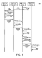
- Figure 5 is a timing diagram illustrating an example algorithm for gathering monitor data using the system 100 of Figure 1.
- the algorithm of Figure 5 is implemented using the global monitor service 132a, which, as already described, is configured to gather information about all devices and services within its underlying hierarchy, and which thus provides a global system landscape view.
- the global monitor service 132a may run as a part of the device level service layer 404 and/or the business process bridging layer 406 of the infrastructure 400 of Figure 4.
- the global monitor service may be requested/called by high-level services that also are running at the device level service layer 404 or the business process bridging layer 406, or through separate device and service monitoring graphical user interfaces (GUIs).
- GUIs graphical user interfaces
- monitor data obtained by the group leader (e.g., 108) is not stored at the group leader, but may be filtered, aggregated, or otherwise processed, before being forwarded to the local monitor service 132b to be stored.
- devices e.g., devices 110-114) run the edge monitor service 132d and form the edge layer.
- group leader monitor services 132c and edge monitor services 132d may be essentially identical in terms of providing, preprocessing, and not storing monitor data, although the edge monitor service 132d is not responsible for managing other devices.
- the edge monitor service 132d is configured to provide monitor data and send it to its group leader using heartbeat messages (e.g., messages sent using an active send queue at some pre-defined interval). More generally, however, gathering monitor data from edge layer devices may be triggered either by timers of the edge devices for sending the heartbeat messages, or by poll messages received at the edge devices from upper tiers/layers.
- Each edge layer device 110-114 reads a local system adaptor (508), which should be understood to be the same or similar to the system adaptor 134 of Figure 1, to obtain up-to-date monitor data.
- system adaptors and related elements are provided in more detail below, with respect to Figures 9-11. Generally, however, it should be understood that such system adaptors serve as data sources to provide monitor data about their respective edge device, as well as about any service(s) running on their respective edge device.
- the local monitor service 132b determines which relevant information within the local monitor data 138 has been changed or updated as a result of the execution of the monitoring algorithm of Figure 5, and only this changed data is submitted to the global monitor data 136, e.g., as part of a delta synchronization message (528). In this way, an amount of transferred and processed data is reduced.
- the delta synchronization may be initiated by a message from the global monitor service 132a to the local monitor service 132b.
- the updated data is preprocessed by the global monitor service 132a (530), and stored in the global monitor data 136. Then, the business data processing systems 104, e.g., supply chain management applications, may access the data from the global monitor data 136. It should be understood from the above description that monitor data from a given edge device is stored in the landscape tree on the path from the edge device itself to the global monitor service 132a. As a result, the monitor data is easily located for use or deletion thereof.
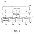
- FIG 6 is a block diagram of a modular monitor service 600 that may represent one or more of the monitor services 132a-132d of Figure 1. That is, the modular monitor service 600 includes the core monitor service 148, which is illustrated in Figure 1 in the context of the group leader monitor service 132c, but which, as explained above, also may be implemented in the context of some or all of the remaining monitor services 132a, 132b, and/or 132d. The modular monitor service 600 also includes the monitor service module 150, which, again, is illustrated in Figure 1 in the context of the group leader monitor service 132c, but which, again, also may be implemented in the context of some or all of the remaining monitor services 132a, 132b, and/or 132d.
- the core monitor service 148 which is illustrated in Figure 1 in the context of the group leader monitor service 132c, but which, as explained above, also may be implemented in the context of some or all of the remaining monitor services 132a, 132b, and/or 132d.
- the modular monitor service 600 also includes the monitor service
- the monitor service module(s) 150 include the system adaptor 134, a communication adaptor 602, a data storage module 604, and a data preprocessor 606. Consequently, associated functionality for these plug-ins, and other functionality, may be added or replaced to the module monitor service 600, without changing the core monitor service 148. Moreover, as described in more detail below, the monitor service module(s) 150 of the same category (e.g., different instances of the communication adaptor 602 or of the data storage module 604) may share a common interface, so that the core monitor service 148 need not be aware of the usage of the different instances/plugins.
- monitor service module 148 Once the core monitor service module 148 is installed within the system 100, various monitor service modules may be installed (704). For example, the monitor service modules 134, 602, 604, and/or 606 may be installed, depending, for example, on the device metadata 130 associated with the device(s) in question, and/or onto which level of the monitor architecture the monitor service module(s) are being deployed. As is also discussed in more detail below, such device metadata may be obtained using the already-installed core monitor service 148, and/or may be obtained from memory.
- the raw monitor data may be pre-processed at the pre-processor module 606 (708). Examples of such pre-processing are provided in conjunction with Figure 5, and further with respect to Figure 14. Generally, however, such pre-processing acts on incoming data to reduce an amount of data to be sent over the network connection(s), using, e.g., filtering and aggregation.
- the processed and stored data may be propagated, and queries for new data (e.g., by polling) may be executed using the communications adaptor 602 (712).
- the communications adaptor 602 may be configured to ensure communication between services/devices, may hide unreliable or out-of-order data transfers, and may hide the core monitor service 148 from effects of different communications protocols/hardware.
- the communications adaptor 602 may be considered to be separate from the monitor service 132a-132d, and, e.g., may be deployed separately (i.e., at separate times) from either the core monitor service 148 or monitor service modules 134, 602, or 606.
- Different operations and uses of the communications adaptor 602 are provided below, with respect to the examples of Figures 8, 12, and 13.
- Figure 7B is a flowchart illustrating additional example operations of the system 100.
- the core monitor service 148 is not initially installed. In many cases, however, the core monitor service 148 may be needed in order to proceed with further operations of the system 100. For example, during a registration process of a new device within the system 100, registration protocol may require installation and availability of the core monitor service 148 (see, e.g., the examples of Figures 15-17 for a discussion of an example registration protocol for registering a new device with the system 100).
- the core monitor service may be installed (722), and additional monitor data may be obtained therefrom (724).
- additional monitor data may be obtained therefrom (724).
- a full-scale device registration with the system monitor 132 also may be executed at this point, if necessary.
- appropriate monitor service module(s) 150 may be deployed (726), so that collection and/or transmission of additional monitor data may proceed.
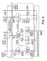
- a system landscape database 806 is included and activated in the Figure 8 example of the core monitor service 148 (e.g., the core monitor service 148 may be associated with the global monitor service 132a or the local monitor service 132b, in which case the system landscape database 806 may represent, include, or otherwise be associated with the global monitor data 136 or the local monitor data 138, respectively).
- the query router 804 may attempt to obtain the requested monitor data from the system landscape database 806.
- the query monitor 806 may query the desired monitor data from a monitor service running on a parent device, e.g., a different device that manages the device that is implementing the core monitor service 148 (for example, the group leader monitor service 132c may query the local monitor service 132b, or the local monitor service 132b may query the global monitor service 132a).
- the current monitor service 148 may manage the queried system (i.e., is a parent to the queried system), in which case a lower level monitor service will be addressed to collect the desired monitor data.
- the queried device may be unknown to the core monitor service 148 of Figure 8, in which case the query may be forwarded to the upper layer which manages more systems, and, ultimately, may proceed to the global monitor service 132a, which may then forward the query to the appropriate local monitor service 132b.
- each monitor service 132b-132d is provided with a parent monitor service that is assigned during registration of the monitor service (see, e.g., Figures 15-17, below).
- This child-parent information may be stored in the system landscape database 806, and/or in other memory, as a property, from which a tree-shaped topology may be generated.
- the tree-shaped topology may be traversed to determine the next hop.
- the next/intervening hop may be obtained from a routing table, using an appropriate table look-up.
- such separate routing tables may use more memory than determining the routing information from the tree-shaped topology, but may be more efficient and/or faster.
- Figure 8 is discussed in terms of the ping requestor 808, it should be understood that other techniques may be used for determining a status of elements of the system landscape of the system 100, e.g., other echo requests used to test a reachability of the system(s) and/or to test network delays. Further, it should be understood that the core monitor service 148 also may receive, and thereafter respond to, ping requests from other monitor services, as shown. Actual implementation of a transport protocol that ensures reliable data transfer of the ping (or other) status requests may be implemented as a task of the communication adaptor 602, as discussed in more detail below, with respect to Figure 12.
- the core monitor service 148 also includes a heartbeat transmitter 810, which may be implemented as a service configured to send a heartbeat message to a parent monitor service, so as to indicate that the device (on which the core monitor service 148 is deployed) is still running.
- the heartbeat transmitter 810 may be triggered by a timer, where the time interval between two messages may be defined in associated heartbeat settings.
- the interval may be chosen with respect to resource-constraints, so that small devices with limited power supply and network capabilities may use a greater time interval than more powerful devices (e.g., well-connected servers).
- a metric may be used to define a default interval customized for each device type (e.g., for a sensor device, PDA, or laptop). Additionally, the value of the interval and other associated settings may be adjustable by the user, e.g. a system administrator of the infrastructure of Figure 4.
- the heartbeat sender 810 may be configured to transmit at least some monitoring data, as well, which if received at the core monitor service 148 from another monitor service, may be used to update the system landscape database 806.
- the heartbeat settings may be used to define which such monitor data should be sent, along with the heartbeat messages. In so doing, an amount of network traffic, power and other resources may be conserved.
- relatively-higher tier monitor services may avoid performing at least some polling of lower-tier services, since the upper-tier services may already have the desired monitor data.
- the device on which the core monitor service 148 is deployed may include the additional monitor data along with heartbeat messages by executing queries on the monitoring data storage, or by reading system adaptors 134 (see Figures 6 and 9-11).
- Heartbeat messages do not have to be sent over reliable communication channels, to the extent that the ping requestor 8.08 may, in response to an expected heartbeat message that does not come through, send an additional request, e.g., if two consecutive pings are missing. Therefore, even if the communication channels are unreliable, and heartbeat messages are lost, the core monitor service 148 may continue to function. Accordingly, protocols such as, for example, the lightweight and connection-less User Datagram Protocol (UDP) may be used.
- UDP lightweight and connection-less User Datagram Protocol
- the system adaptors 134 may implement a common interface for communicating with the core monitor service 148, while implementing whatever other interfaces are necessary for monitoring (and, potentially, controlling) the various heterogeneous services and/or devices that may be present, so that the core monitor service 148 need be aware of only this common interface in order to communicate with a large number of types of the system adaptors 134 (and, thereby, a large number of types of services and devices).
- the core monitor service 148 may be capable of communicating with a large number of the system adaptors 134 (using just the common interface), the core monitor service 148 either does not or cannot determine which of the system adaptors 134 is appropriate for a given task. Rather, a system adaptor manager 902 is used in making such a determination of a particular/correct one of the system adaptors 134 for a given task or setting. As such, the system adaptor manager 902 represents an example of the module manager(s) 150, and provides an abstraction layer between the core monitor service 148 and the system adaptor(s) 134. Accordingly, the core monitor service 148 may be relieved of the duty of tracking, selecting, or otherwise managing the various instances or possibilities of the system adaptors 134, much less of the services or devices themselves.
- the system adaptors 134 include a basic information adaptor 906 and an OSGi adaptor 908.
- the basic information adaptor 906 refers generally to service and/or device information that may be collected and used, e.g., in the system 100, such as the many and various examples of device metadata 130 provided above.
- the OSGi adaptor 908 generally refers to the fact that the system adaptors 134 may support such standardized protocols as OSGi to get information about devices that do not have one of the monitor services 132a-132d installed.
- Other examples for such protocol standards include the Java API platform JSR232 (which includes OSGi), as well as Java APIs for Bluetooth, JSR82.
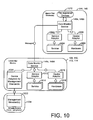
- a lower-tier (e.g., group leader or edge) device 108, 110, 112, and/or 114 may represent a relatively more resource-poor device, and may include the core monitor service(s) 148c, 148d.
- the devices 108, 110, 112, 114 include a service adaptor 1012 (for interfacing with a plurality of services 1014) and a device adaptor 1016 (for interfacing with a plurality of instances/types of device hardware 1018).
- the devices 108, 110, 112, 114 also include a separate device adaptor(s) 1020 that may be used to communicate with devices, e.g., a device 1024, that implements such standards 1022.
- the device 1024 may represent a sensor mote or cell phone that is running the management standard 1022 (e.g., OSGi), so that the core monitor service 148 may communicate therewith using the standard 1022.
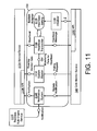
- FIG 11 is a block diagram of another example implementation of the system adaptors of Figures 1, 6, and 9.
- the system adaptor(s) 134 is illustrated as communicating with the core monitor service 148.
- the system adaptor(s) 134 may communicate with the core monitor service 148 using an API 1102 of the core monitor service 148 that is common to all of the system adaptor(s) 134.
- the system adaptor(s) 134 also communicate with a service and/or device 1104 using an API 1106, which is specific to the service/device 1104 and to the specific, associated instance of the system adaptor 134 in Figure 11.
- the system adaptor 134 includes a notification system 1108 that is configured to receive notifications from the core monitor service 148 (e.g., from the update notification transmitter 812 of Figure 8).
- the core monitor service 148 may send updates regarding changes in monitor data, or registration of new services or new devices.
- the notification system 1108 (which may thus be understood to be included in the recipient registry 814) may subscribe to particular notifications, or types of notifications, and so may receive notifications on a periodic or scheduled interval.
- the system reader 1112 may provide the monitor data to a heartbeat transmitter 1114.
- the heartbeat transmitter 1114 generally speaking, is configured to periodically send a life-signal to the core monitor service 148.
- the heartbeat transmitter 1014 also may receive and transmit monitor data from the service/device 1104 (e.g., status values), which allows for a reduction in messaging overhead.
- heartbeat settings 1116 may include parameters associated with the heartbeat transmitter 1114, such as, for example, a time interval between heartbeat messages.
- processing threads may be used for various tasks, including monitor service maintenance threads, or adaptor threads. Such threads (for, e.g., context switching, thread scheduling, or inter-thread communication) may be created and managed, as needed.
- the monitor service thread may be used to keep monitor data, as stored in system landscape databases 806 and/or the global/local monitor data 136/138, up-to-date, and may further be used to manage a status of lower-tier services and devices.
- System adaptor threads may be implemented separately from the monitor service maintenance thread, so that system adaptors 134 do not block the monitor service maintenance thread by performing complex or time-intensive tasks.
- the system adaptors 134 may run as separate threads, or may be executed by a thread of an associated monitor maintenance service. In the latter case, the monitor service maintenance thread may be blocked for the time of executing a maintenance function of the system adaptors 134.
- the system adaptors 134 which may be called by the monitor service, still can create temporary threads that do time-consuming work in the background, so the monitor service thread is not blocked.
- System adaptors that use their own threads may generally be more powerful. Also, such system adaptors do not block the monitor service, and so may perform time-consuming tasks, and/or wait for I/O interrupts. Additionally, such system adaptors have more freedom in deciding when to be activated. Thus, such system adaptors are not dependent on calls by the monitor service at an undefined point in time. Timers can be used to actively send heartbeats messages and to update landscape values.
- system adaptors may be implemented as passive components that use the monitor service thread. In such cases, an overhead of creating and managing threads may be avoided, at a cost of blocking the monitor service while executing the system adaptor in question.
- Figure 13 is a block diagram of another example implementation of the communication adaptor(s) 602 of Figure 6.
- the communication adaptor manager (abstraction layer) 802a, 802b may support both local method calls and network communication. Furthermore, the communication adaptor manager (abstraction layer) 802a, 802b may operate to make communication protocols and network devices opaque to the core monitor service 148.
- the communication adaptor manager 802a, 802b hides currently-used protocols (e.g., Transfer Contorol Protocol (TCP), Uniform Datagram Protocol (UDP), Internet Protocol (IP), Hyper Text Transfer Protocol (HTTP), or File Transfer Protocol (FTP), which may work on different ISO/OSI layers, and/or which may be combined.
- the communication adaptor manager 802a, 802b also may hide network devices 1204 (e.g., Bluetooth, modem, or WiFi devices).
- the communication adaptor manager 802a, 802b also may hide certain communication concepts (e.g., message passing, sockets, shared memory, or API calls).
- the communication adaptor manager 802a, 802b may load or unload, for example, a TCP adaptor 1302, a UDP adaptor 1304, or an API call Adaptor 1306, which may each present a common interface to the core monitor service 148.
- a TCP adaptor 1302 a UDP adaptor 1304, or an API call Adaptor 1306, which may each present a common interface to the core monitor service 148.
- the example of Figures 12 and 13 may allow avoidance of dealing with protocols, network devices, sequence numbers, or transmission errors.
- each of the adaptors 1302-1304 is identified as being associated with either network (1302, 1304) or local (1306) communication. Further, each of the adaptors 1302-1304 is identified as being associated with either reliable (1302, 1306) or unreliable (1306) communication. Each of the adaptors 1302-1306 also may be associated with a unique identifier (Adaptor ID), for use by the communication adaptor manager 802a, 802b in selecting or loading the respective adaptor.
- Adaptor ID unique identifier
- unreliable data transfer may be much simpler and therefore less resource consuming than reliable transfer. Therefore, unreliable data transfer may be preferred, where possible.
- Some functionality, however, such as pinging a system, may require reliable data transfer (and corresponding communication adaptor).
- the core monitor service 148 may send and receive different types of messages, and the communication adaptor manager 802a, 802b may be used to select a corresponding, appropriate communication adaptor to execute the sending or receiving.
- the core monitor service 148 may need to send a message over a network, using a lightweight and unreliable transport protocol.
- the communication adaptor manager 802b may locate the UDP adaptor 1304, among all loaded adaptors, which implements an unreliable network communication. The communication adaptor manager 802b then forwards the message to the UDP adaptor 1304, which performs the actual communication.
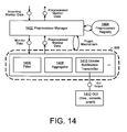
- Figure 14 is a block diagram of an example implementation of the preprocessor module 606 of Figure 6.
- the preprocessor module 606 may be used by one or more of the various monitor services 132b-132d to process monitor data locally before forwarding the processed monitor data to the next higher tier of the architecture of the system 100 of Figure 1.
- the preprocessor module(s) 606 may include a filter 1406, an aggregator 1408, and an update notification transmitter 1410.
- the filter 1406 may be configured to remove certain types of monitor data, or certain amounts.
- the aggregator 1408 may be configured to combine received messages for transmission of a combined message.
- the group leader monitor service 132c may receive a message from each edge device 110-114 for aggregation thereof, or may receive a series of message from a single edge device (e.g., the edge device 110).
- different ones of the preprocessor modules may register at the core monitor service 148.
- monitor data e.g., status values
- each of the registered preprocessors is executed.
- a first preprocessing module may receive the raw monitor data as a parameter(s), and may return a preprocessed data set. Subsequently, the next preprocessor is started, and received the preprocessed output data from the first preprocessor. Accordingly, each preprocessor may be executed, working on the output data of its predecessor.
- modules e.g., plug-ins
- two modules may register with the core monitor service 148 and/or the preprocessor manager 1402.
- the first module may delete all data of a specific service or device, while the second module may compute the average CPU utilization over all monitored devices.
- the result is different if the order of the two modules changes, because then all monitored services and devices are taken into account, including the specific service or device to be deleted.
- the preprocessor manager 1402 may, e.g., during registration, set the appropriate execution order.
- a number and type of preprocessor modules 606 may be unknown at design-time, it may be difficult to assign an absolute execution order, particularly when the preprocessor modules may be loaded dynamically at runtime. Consequently, one option is to create groups of the preprocessor modules 606, so as to order the preprocessor modules 606 according to group.
- Each preprocessor module 606 may be associated with a group identifier, so as to be put into the correct group during registration. Then, the groups may be executed in order on a group-level, if not at the level of individual preprocessor modules.
- Groups may be ordered based on, for example, a priority and/or type of pre-processing performed. For example, a first group may include preprocessor modules that must work on raw data, while a second group may work on already-preprocessed data, and a third group may process final data.
- a modular or plug-in concept for the preprocessing modules 606 e.g., 1406-1410 may increase a scalability of the system 100 of Figure 1, and may address resource-constraint issues. For example, scalability may be increased by relieving the global monitor service 132a and the local monitor service 132b from some or all preprocessing tasks.
- the modular architecture allows the monitor service 132a-132b configurable to the needs and capabilities of each device.
- monitor service modules 150 may be implemented.
- a data storage module 604 may be used.
- a different technology for storing monitor data in the global monitor data 138 may be chosen than is chosen for storing monitor data in the local monitor data 136, e.g., either may store data in one or more of a database, a text file, an in memory data-structure, or virtually any other kind of data storage.
- Use of the data storage module 604 may make such differences opaque to the monitoring service in question, using the various techniques described above with respect to Figures 6-14.
- the monitor data storage may be encapsulated by a well-defined interface, and the interface may serve as an abstraction layer from the actual data storage system.
- FIG. 15 is a block diagram of a system 1500 illustrating a registration protocol for use with the system 100 of Figure 1.
- a group leader device 1502 which may be a portable device (e.g., a PDA or laptop), enters into an area of a group leader device 1504.
- the group leader device 1504 is a group leader of a plurality of edge devices 1506a, 1506b, 1506c of a sensor network.
- the group leader device 1504 and the edge devices 1506a, 1506b, 1506c may be involved in any number of sensor network applications, including, for example, inventory management or hazardous material tracking.
- the group leader device 1504 (which may be, for example, the same as the edge devices 1506a, 1506b, 1506c, or which may be a WiFi access point or a base station, as referenced above) may be in the process of collecting information (i.e., monitor data) associated with inventory in a warehouse.
- monitor data may include a type and quantity of stocked goods for sale, and/or current temperature information in a vicinity of the stocked goods (e.g., to detect possible spoilage of food products).
- the group leader device 1502 may enter the area of the group leader device 1504, such as when an employee enters the area with a PDA or other computing device, and wishes to obtain desired monitor data.
- the group leader device 1502 may wish to collect the monitor data for local use by the employee, and/or may itself collect/transmit monitor data to a global monitor service 1508. In the latter case, for example, the group leader device 1502 may have certain computing resources or capabilities not available (or, at least, not currently available) in the group leader device 1504.
- the group leader device 1502 may actually be currently acting as a group leader to a plurality of edge devices (not shown in Figure 15), or may be referred to as a group leader device in the sense that sufficient computing resources are present to act at the group leader tier of the infrastructure described herein (e.g., to split messages for distribution to edge devices, or to filter/aggregate messages from the edge devices for subsequent transmission).
- the group leader device 1504 it may be the case that the group leader device 1504 has failed, or is about to fail (e.g., due to low battery power), or is required to re-locate, so that the group leader device 1502 is being re-located for the purpose of assuming the duties of the group leader device 1504.
- the global monitor service 1508 includes global monitor data 1510, and operates on a device 1512 (which may include, as described herein, a PC or similarly-powerful computer).
- the global monitor data 1510 may include global landscape data related to the system 1500 as a whole, including other elements not shown in Figure. 15.
- the global monitor data 1510 may include device metadata describing the group leader 1504 and the edge devices 1506a, 1506b, 1506c (including, for example, both static and dynamic device capabilities).
- the system 1500 further includes a local monitor service 1514, with local monitor data 1516 and running on a device 1518.
- the device 1518 may include, for example, a laptop computer or a Stargate computer, as described.
- the system 1500 may include a local monitor service 1520, with local monitor data 1522 and running on a device 1524.
- the group leader device 1502 may need to register with the global monitor service 1508 in order, for example, to establish a connection 1526 with the group leader 1504.
- the group leader device 1502 and the group leader device 1504 may have overlapping abilities to communicate with one another; e.g., both may have Bluetooth capabilities. Even so, the group leader device 1502 may be unaware that the group leader device 1504 has Bluetooth capabilities, and, moreover, the group leader device 1502 may have no local communication service (e.g., adaptor/module) that is compatible both with Bluetooth and with whatever service(s) are being run on the group leader device 1504 (e.g., the temperature reporting service referenced above).
- a local communication service e.g., adaptor/module
- the global monitor service 1508 may be well aware of all such information, as stored within the global monitor data 1510 (e.g., appropriate service metadata and/or device metadata).
- information regarding the group leader device 1504 also may be stored in the local monitor data 1516, as should be understood from the description above.
- the global monitor service 1508 is (indirectly) capable of establishing the connection 1526, since, for example, the global monitor service 1508 may be able to determine which communications services (adaptors/ modules) are needed, and may then download and/or inject such a service(s) onto the group leader device 1502.
- the global monitor service 1510 also may communicate with the group leader device 1504, in order to ensure (by injecting, if necessary) that the group leader device 1504 not only has Bluetooth (or other communication protocols/standards), but also has a local service that is compatible both with Bluetooth and with a corresponding service on the group leader device 1502.
- Such registration may be associated with a number of difficulties. For example, such registration may represent a security issue, since unregistered and possibly malicious devices should not generally be monitored and integrated into the system 1500. Also, frequent exchanges of registration messages may consume valuable bandwidth, battery power, or other communications resources. If devices are not registered, though, then such devices may be un-identified and unaccessed by the rest of the system 1500.
- the group leader device 1502 has a monitor service installed thereon (although not shown in Figure 15).
- a monitor service may include the various implementations described herein, including the modular monitor service of Figure 6, or may include a non-modular, e.g., integrated, monitor service.
- the group leader device 1502 and its installed monitor service thus attempt to join the network(s) of the system 1500, including registering at the global monitor service 1508.
- the group leader device 1502 includes a registration system 1528 and registration data 1530.
- the registration system 1528 is configured to exchange registration messages 1532, 1534, 1536, and 1538 with one or more of the local monitor services 1514, 1520 (and/or with the global monitor service 1508).
- the registration data includes information about the connecting monitor service of the group leader device 1502, such as, for example, metadata related to a current status of the group leader device 1502, or device metadata related to the group leader device 1502.
- the registration data also may include initial sensor status/values information (e.g., to avoid overhead caused by an initial polling for such values, which would take place right after registration, since data is outdated or not existent. In cases where an excessive amount of values would be included in the registration data, then at least static data values may be sent).
- registration data 1530 is illustrated conceptually as/in a memory in Figure 15, it should be understood that the registration data 1530 may simply represent values collected by the group leader device 1502 (e.g., by the registration system 1528 and/or by a monitor service of the group leader device), either during or before registration takes place.
- the group leader device 1502 may have a memory in some example implementations.
- a local memory e.g., the local monitor data 1516, 1522
- the registration system 1528 and registration data 1530, or variations thereof, may be implemented within other ones of the devices and monitor services of Figure 15.
- the described registration protocol may be implemented as a simple, e.g., connectionless, protocol, that is robust. Additionally, the registration protocol is configured to support both active registration (e.g., initiated by a connecting device) and passive registration (e.g., initiated by a connected network device). Consequently, as described, the registration process may be started by either device.
- the group leader device 1502 as an unregistered-but-now registering device sends out a solicitation message 1532.
- the solicitation message 1532 which may be sent as a broadcast message, may contain a request for, or identification of, a specific type of same or next-higher level monitor service, and the request may be based in part on device capabilities of the connecting device. For example, if the (registering) group leader device 1502 has certain capabilities (e.g., is a mobile phone), then it may try to locate other group leader devices (e.g., the group leader device 1504, i.e., a monitor service thereof) and/or local monitor services (e.g., 1514, 1520), rather than the global monitor service 1508.
- group leader devices e.g., the group leader device 1504, i.e., a monitor service thereof
- local monitor services e.g., 1514, 1520
- the registration system 1528 may re-send the solicitation message 1532 with an identification of a next-higher level (going up from lower to higher level monitor services). Further, if the solicitation message 1532 is lost, then the registration system 1528 may simply send another solicitation message, e.g., after a timeout. Solicitation messages that are received twice are not an issue, since this is the initial step of the protocol. Therefore, a lightweight and connectionless transportation protocol, e.g., UDP, may be sufficient.
- UDP connectionless transportation protocol
- the advertisement message 1534 may be sent, for example, either in response to a timer or to the solicitation message 1532.
- the advertisement message 1534 may include an identification of a type of monitor service that is sending the advertisement message 1534 (e.g., the local monitor service 1520 in the example of Figure 15).
- the advertisement message 1534 may be sent as a broadcast message, and may be sent by any or all of the devices described herein (except, generally, the various edge devices, to the extent that the edge devices do not typically have any child monitor services connected thereto).
- the advertisement message 1534 provides a fail-safe mechanism in case the solicitation message 1534 is lost, and also may act as an initiator of the registration process, e.g., for devices that do not send solicitation messages.
- the group leader device 1502 may, as referenced above, stop sending solicitations after a specified time period, or if devices cannot detect network changes.
- the advertisement message 1530 such devices may be "reactivated.”
- lost advertisement message are not disruptive, in that they may be resent from time to time.
- a connecting/registering device such as the group leader device 1502 may respond to the advertisement message 1534 once by sending a registration message 1536.
- the registration message 1536 may contain, for example, information about monitored data, landscape metadata, device metadata, and/or actual monitored (e.g., sensor) values.
- the registration system 1536 may ensure that duplicates of the registration message 1536 are not problematic, by allowing only one message-triggered registration message 1536 during a registration process. That is, the registration system 1536 may be configured to ignore any additional advertisement message(s) 1534, once the registration message 1536 is sent.
- the registration message 1536 then obtains a confirmation message 1538 to ensure that the registration was processed successfully. If no confirmation has arrived after a pre-determined time, the registration message 1536 may be resent. Duplicate registration messages are no problem in such implementations, because one registration may be allowed to override another registration without causing any harm. Additionally, or alternatively, duplicated registration messages may simply be ignored if the relevant service or device is already registered.
- the confirmation message 1538 may be sent by the managing monitor service (e.g., the local monitor service 1520).
- the registration process finishes when the registering device (the group leader device 1502) receives the confirmation message 1538 (if the confirmation message 1538 is not received, e.g., is lost, then the group leader device 1502 may simply re-send the registration message 1536).
- the now-registered monitor service of the group leader device 1502 may then begin its assigned monitoring tasks.
- the registration protocol of Figure 15 allows for connectionless and unreliable data transfer, so that simple and robust protocols, e.g., UDP, may be used.
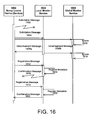
- a solicitation message is sent from the group leader device 1502 (e.g., from a group leader monitor service installed thereon) to the local monitor service 1520, but is not received (1602). That is, the solicitation message includes an identification that it is a local monitor service that is desired as a parent device, but no such potential parent device receives or responds to the message.
- a second solicitation message(s) is/are sent (1604), which is received at both the local monitor service 1520 and the global monitor service 1508.
- the registration system 1528 may determine that because the sending of the first solicitation message (1602) was unsuccessful, it may be necessary to send a second solicitation message.
- both the local monitor service 1520 and the global monitor service 1508 receive the solicitation message (1604). However, the global monitor service 1508 simply ignores (1606) the solicitation, since the solicitation specifies the local monitor service 1520.
- the local monitor service 1520 sends out an advertisement message (1608a and 1608b).
- the advertisement message may be sent (1608a) in response to the sending of the solicitation message(s) (1604), or may be sent based on a timer value.
- the sending of the additional advertisement message (1608b) as part of a broadcast thus arrives at the global monitor service 1508, but is ignored (1610).
- the group leader device 1502 then sends a registration message (1612), causing the local monitor service to register associated metadata (1614).
- the registered metadata may be forwarded to the global monitor service 1508 (e.g., using delta synchronization).
- a confirmation message may be sent, but, in the example of Figure 16, is not received at the registration system 1528 (1616).
- the registration system 1528 of the group leader device 1502 simply resends the registration message (1618), which is then received again at the local monitor service 1520, and either re-registered (1620) or ignored.
- a confirmation message is sent again, and this time is received at the group leader device 1502 (1622), thus ending the registration process.
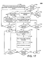
- FIG 17 is a flowchart 1700 illustrating example operations of the system 1500 of Figure 15.
- a connecting monitor service e.g., a monitor service of the group leader device 1502, which may include or be associated with the registration system 1528
- broadcasts a solicitation message e.g., the solicitation message 1532
- the solicitation message 1532 including an identification of a desired parent service from within the hierarchical monitor architecture of the system 1500 (1702).
- the parent monitor service may continue waiting for a pre-defined timer (1706). Thus, if the timer is reached, or if the solicitation message is received at the parent monitor service, then the parent monitor service may receive the resulting advertisement message, e.g., the advertisement message 1534 (1708). As should be understood, then, the advertisement message 1534 may be sent whether the solicitation message 1532 is received or not, thus increasing the likelihood of connection/registration of the connecting device.
- the connecting device may re-send the solicitation message 1532 (1712), perhaps identifying a next-higher level of the hierarchical monitor architecture as the desired parent service (e.g., the global monitor service 1508 instead of the local monitor service 1520, 1514).
- the process may continue until a registration and/or advertisement message(s) are exchanged. Otherwise, the process is stopped (1716).
- the time-out condition may refer literally to a period of time that has passed, or may refer to the sending of a pre-defined number of (a certain type of) message(s).
- the advertisement message may be resent (1708), according to its associated timer (1706), even if the process was previously stopped or failed.
- any "stop" condition in Figure 17, including the stop condition (1716) may be temporary, and the process may continue after some further-defined period is reached.
- the connecting device may send a registration message, e.g., the registration message 1536, to the parent monitor service identified in the advertisement message (1718). If the registration message is not received (1720), and a timer is not reached (1722), then the connecting device may re-send the registration message (1718).
- the registration message may include monitor data, so that, if the registration message is received (1720), the registration message may be propagated up the hierarchy (1726), e.g., to the global monitor service 1508. In this case, the monitor data, including metadata about the connecting device and actual sensor values may be saved at some or all of the intervening devices (1728), e.g., the local monitor service 1520.
- the parent monitor service may send a confirmation message (1730), e.g., the confirmation message 1538. If the confirmation message is not received (1732), and a time-out has not been reached (1734), then the registration message may be re-sent (1718), and the above-described process may be repeated, in whole or in part. If the time-out is exceeded (1734), or if the confirmation message is received, then the registration process ends, as well (1724).
- the just-described registration protocol(s) may be implemented when the connecting device (e.g., the group leader device 1502) already has a monitor service installed thereon. As described above with respect to Figure 7B, however, if the connecting device does not have a monitor service installed thereon, then a pre-registration process may be conducted in which, as described above, a boot-strapping technique may be used in which the core monitor service 148 is installed, and then is used to execute the remaining registration processes of Figures 15-17.
- a robust and reliable registration protocol of Figures 15-17 allows for the use of unreliable/connectionless communications protocols, while minimizing an amount of network bandwidth required for the registration process. For example, network bandwidth may be conserved by stopping re-sending of one or more of the messages after a certain period of time.
- network bandwidth may be conserved by stopping re-sending of one or more of the messages after a certain period of time.
- each time the registration protocol requires resending messages after timeouts there is a possibility that either the connecting device or parent service may have lost a connection, and this possibility may lead to a "stuck" state for some or all of the system 1500.
- each re-sent message may be re-sent for a limited number of times only, and, if no successful registration is achieved the entire registration process may restart.
- Implementations of the various techniques described herein may be implemented in digital electronic circuitry, or in computer hardware, firmware, software, or in combinations of them. Implementations may implemented as a computer program product, i.e., a computer program tangibly embodied in an information carrier, e.g., in a machine-readable storage device or in a propagated signal, for execution by, or to control the operation of, data processing apparatus, e.g., a programmable processor, a computer, or multiple computers.
- data processing apparatus e.g., a programmable processor, a computer, or multiple computers.
- a computer program such as the computer program(s) described above, can be written in any form of programming language, including compiled or interpreted languages, and can be deployed in any form, including as a stand-alone program or as a module, component, subroutine, or other unit suitable for use in a computing environment.
- a computer program can be deployed to be executed on one computer or on multiple computers at one site or distributed across multiple sites and interconnected by a communication network.
- Method steps may be performed by one or more programmable processors executing a computer program to perform functions by operating on input data and generating output. Method steps also may be performed by, and an apparatus may be implemented as, special purpose logic circuitry, e.g., an FPGA (field programmable gate array) or an ASIC (application-specific integrated circuit).
- FPGA field programmable gate array
- ASIC application-specific integrated circuit
- processors suitable for the execution of a computer program include, by way of example, both general and special purpose microprocessors, and any one or more processors of any kind of digital computer.
- a processor will receive instructions and data from a read-only memory or a random access memory or both.
- Elements of a computer may include at least one processor for executing instructions and one or more memory devices for storing instructions and data.
- a computer also may include, or be operatively coupled to receive data from or transfer data to, or both, one or more mass storage devices for storing data, e.g., magnetic, magneto-optical disks, or optical disks.
- Information carriers suitable for embodying computer program instructions and data include all forms of non-volatile memory, including by way of example semiconductor memory devices, e.g., EPROM, EEPROM, and flash memory devices; magnetic disks, e.g., internal hard disks or removable disks; magneto-optical disks; and CD-ROM and DVD-ROM disks.
- semiconductor memory devices e.g., EPROM, EEPROM, and flash memory devices
- magnetic disks e.g., internal hard disks or removable disks
- magneto-optical disks e.g., CD-ROM and DVD-ROM disks.
- the processor and the memory may be supplemented by, or incorporated in special purpose logic circuitry.
- implementations may be implemented on a computer having a display device, e.g., a cathode ray tube (CRT) or liquid crystal display (LCD) monitor, for displaying information to the user and a keyboard and a pointing device, e.g., a mouse or a trackball, by which the user can provide input to the computer.
- a display device e.g., a cathode ray tube (CRT) or liquid crystal display (LCD) monitor
- keyboard and a pointing device e.g., a mouse or a trackball
- Other kinds of devices can be used to provide for interaction with a user as well; for example, feedback provided to the user can be any form of sensory feedback, e.g., visual feedback, auditory feedback, or tactile feedback; and input from the user can be received in any form, including acoustic, speech, or tactile input.
- Implementations may be implemented in a computing system that includes a back-end component, e.g., as a data server, or that includes a middleware component, e.g., an application server, or that includes a front-end component, e.g., a client computer having a graphical user interface or a Web browser through which a user can interact with an implementation, or any combination of such back-end, middleware, or front-end components.
- Components may be interconnected by any form or medium of digital data communication, e.g., a communication network. Examples of communication networks include a local area network (LAN) and a wide area network (WAN), e.g., the Internet.
- LAN local area network
- WAN wide area network
Landscapes
- Engineering & Computer Science (AREA)
- Business, Economics & Management (AREA)
- Physics & Mathematics (AREA)
- General Business, Economics & Management (AREA)
- Human Resources & Organizations (AREA)
- Marketing (AREA)
- Operations Research (AREA)
- Quality & Reliability (AREA)
- Strategic Management (AREA)
- Tourism & Hospitality (AREA)
- Economics (AREA)
- Entrepreneurship & Innovation (AREA)
- General Physics & Mathematics (AREA)
- Theoretical Computer Science (AREA)
- Health & Medical Sciences (AREA)
- Computing Systems (AREA)
- General Health & Medical Sciences (AREA)
- Medical Informatics (AREA)
- Computer Networks & Wireless Communication (AREA)
- Signal Processing (AREA)
- Telephonic Communication Services (AREA)
- Computer And Data Communications (AREA)
Abstract
Description
- This description relates to ubiquitous computing technologies.
- Smart item technologies may include, for example, radio-frequency identification (RFID) systems, embedded systems, sensor motes, and/or sensor networks, and may be used, for example, to provide business software applications with fast access to real-world data. For example, smart item technologies may be used support the detection, reading, or writing of RFID tags, as well as to support communication with, and control of, wireless sensor networks and embedded systems. In many instances, smart items may include devices having local processing power, memory, and/or communication capabilities, that are capable of providing data about the device and its properties, or information about a current state or environment of the smart item devices. Accordingly, some such devices may be used in the execution of service components of back-end or underlying business applications, and, in particular, may do so in a collaborative way, e.g., by forming mobile ad-hoc networks to collect, process, or transmit business data.
- Examples of smart item devices include an RFID tag, which may be passive or active, and which may be attached to a real-world object and used to provide product or handling information related to the object. Other examples of smart item devices includes various sensors, such as, for example, environmental sensors (e.g., a temperature, humidity, or vibration sensor), which, as just referenced, may be capable of communicating to form one or more sensor networks. These and other types of smart item devices also may include embedded systems, which may refer generally to any system in which a special-purpose processor and/or program is included, and/or in which the system is encapsulated in the device being controlled.
- Through automatic real-time object tracking, smart item technology may provide businesses with accurate and timely data about business operations, and also may help streamline and automate the business operations. Accordingly, cost reductions and additional business benefits (e.g., increased asset visibility, improved responsiveness, and extended business opportunities) may be obtained.
- According to one general aspect, a method includes transmitting, from a registering monitor service at a first tier of a hierarchical, multi-tier monitoring architecture for a device network, a solicitation message identifying both the registering monitor service, and a registered monitor service associated with a second, higher tier of the hierarchical, multi-tier monitoring architecture. The method also includes transmitting, from the registered monitor service, an advertisement message indicating an identity and availability of the registered monitoring service for registration, and transmitting, from the registering monitor service, a registration message including registration data associated with the registering monitor service. The method also includes registering the registering monitor service within the hierarchical, multi-tier monitoring architecture, based on the registration data.
- Implementations may include one or more of the following features. For example, the method may include transmitting, from the registered monitor service, a confirmation message confirming registration of the registering monitor service.
- In transmitting the solicitation message, the solicitation message may be transmitted to the second, higher tier, after a previous transmitting to an intervening tier does not result in receiving the advertisement message. Transmitting the solicitation message also may include broadcasting the solicitation message at a pre-determined time interval.
- Transmitting the advertisement message may include transmitting the advertisement message based on the solicitation message. Transmitting the advertisement message may include transmitting the advertisement message based on a pre-determined time interval, and independently of the solicitation message.
- Transmitting the registration message may include including, within the registration data, device metadata within the registration message and associated with a device on which the connecting service is deployed, and/or including, within the registration data, service metadata within the registration message and associated with a service deployed on the device. Transmitting the registration message also may include including, within the registration data, sensor values obtained by a sensor associated with the connecting service.
- Transmitting the registration message may include re-transmitting the registration message until the confirmation message is received or until a time-out condition is reached, and/or may include discarding, at the registering monitor services, a further advertisement message received after the registration message is transmitted. Additionally, or alternatively, transmitting the registration message may include storing the registration data using at least one device associated with the registered monitor service, and/or updating global monitor data for the hierarchical, multi-tiered monitor architecture, based on the registration data, to reflect the registration of the registering monitor service with a global monitor service.
- A core monitor service may be deployed onto the registering monitor service, and device metadata associated with a device on which the registering monitor service is deployed may be determined. At least one monitor service module may be deployed onto the device, based on the device metadata. The solicitation message may be transmitted, the advertisement message may be received, and/or the registration message may be transmitted, using the at least one monitor service module.
- According to another general aspect, a system includes a monitor service configured to obtain and report monitor data regarding a device network at a first level of a hierarchical, multi-tiered monitor service. The monitor service includes a registration system configured to send a solicitation message from the monitor service, the solicitation message specifying, by tier, a registered monitor service at a higher-level tier of the hierarchical, multi-tiered monitor architecture, the registration system being further configured to receive an advertisement message from the registered monitor service, determine that the registered monitor service is a member of the specified tier based on the advertisement message, and send a registration message to the registered monitor service.
- Implementations may include one or more of the following features. For example, the registration system may be configured to receive a confirmation message from the registered monitor service, in response to the registration and confirming that the monitor service is registered with a global monitor service associated with the device network. The registration message may include registration data that is stored, at least in part, using the global monitor service and any intervening monitor service between the registering monitor service and the global monitor service.
- According to another general aspect, a method includes receiving a solicitation message from a monitor service at a registered monitor service of a hierarchical, multi-tiered monitor architecture for a device network, determining that the monitor service is not registered through the registered monitor service as a member of the hierarchical, multi-tiered monitor architecture, and determining an identification of a tier specified in the solicitation message, the registered monitor service being deployed on the tier. The method may include sending an advertisement message to the monitor service, the advertisement specifying the registered monitor service as being deployed on the tier and available for registration, receiving a registration message from the monitor service, and registering the monitor service within the hierarchical, multi-tiered monitor architecture, based on the registration message.
- Implementations may include one or more of the following features. For example, a confirmation message may be sent to the monitor service. Additionally, or alternatively, sending the advertisement message may include sending the advertisement message in response to the solicitation message. Registering the monitor service may include storing, locally to the registered monitor service, registration data received from the monitor service as part of the registration message, and updating a memory of a higher-tier monitor service, above the registered monitor service, based on the registration data.
- The details of one or more implementations are set forth in the accompanying drawings and the description below. Other features will be apparent from the description and drawings, and from the claims.
- In the drawings,
- Figure 1 is a block diagram of a system for monitoring smart items.
- Figure 2 is a block diagram illustrating an example deployment of the system of Figure 1.
- Figure 3 is a block diagram illustrating a second example deployment of the system of Figure 1.
- Figure 4 is a block diagram of a smart items infrastructure for implementing the systems of Figures 1, 2, and 3.
- Figure 5 is a timing diagram illustrating an example algorithm for gathering monitor data using the system of Figure 1.
- Figure 6 is a block diagram of a modular monitor service that may represent one or more of the
monitor services 132a-132d of Figure 1. - Figure 7A is a flowchart illustrating an operation of the system of Figure 1 using the modular monitor service of Figures 1 and 6.
- Figure 7B is a flowchart illustrating additional example operations of the system of Figure 1.
- Figure 8 is a block diagram of an example implementation of a core monitor service of Figures 1 and 6.
- Figure 9 is a block diagram illustrating a system adaptor manager for use with the modular monitor service of Figure 6 and/or the implementation of the core monitor service illustrated in Figure 8.
- Figure 10 is a block diagram of an example implementation of a system adaptors of Figures 1, 6, and 9.
- Figure 11 is a block diagram of another example implementation of system adaptors of Figures 1, 6, and 9.
- Figure. 12 is a block diagram of an example implementation of a communication adaptor of the modular monitor service of Figure 6.
- Figure 13 is a block diagram of another example implementation of the communication adaptor(s) of Figure 6.
- Figure 14 is a block diagram of an example implementation of a preprocessor module of Figure 6.
- Figure. 15 is a block diagram of a system illustrating a registration protocol for use with the
system 100 of Figure 1. - Figure 16 is a sequence diagram illustrating an example implementation of the registration protocol of Figure 15.
- Figure 17 is a flowchart illustrating example operations of the system of Figure 15.
- Figure 1 is a block diagram of a
system 100 for monitoring smart item devices. In the example of Figure 1, asensor network 102 that includes various smart item devices provides real-world data to one or more businessdata processing systems 104 in a timely and accurate manner, using a local area network 106 (although other sizes or types of networks may be used). For example, thesensor network 102 may includesmart item devices - Although the following description refers primarily to the
sensor network 102 or other sensor network(s) as an example implementation(s), it should be understood that such sensor networks may refer to any network that gathers or obtains information, even if not all of the devices of the sensor network do not have specific sensor functionality associated therewith (e.g., one of the devices of thesensor network 102 may include an actuator). Moreover, it should be understood that virtually any network of devices may be used, alone or in conjunction with one another. Further, devices of such device networks may communicate with one another (e.g., in a peer-to-peer fashion), and/or may communicate, e.g., through appropriate middleware, with the businessdata processing systems 104, or other systems. - In Figure 1, the
device 108 is illustrated as including a central processing unit (CPU) 116, as well as amemory 118. Thus, thedevice 108 should be understood to be capable of various levels of computing capabilities, including, for example, processing or transmitting sensed data (e.g., in the case where thedevice 108 includes, or is associated with, a sensor). Although not specifically illustrated in Figure 1 for the sake of clarity, it should be understood that thedevices sensor network 102, such as a wireless network and/or a peer-to-peer network. - Thus, the
sensor network 102 may be used to collect, process, filter, aggregate, or transmit data that may be useful to the businessdata processing systems 104. For example, the businessdata processing systems 104 may include inventory management systems, supply chain management systems, retail store management systems, warehouse management systems, and any other system(s) that may be used to execute business processes with respect to real-world objects, where such real-world objects may include, for example, products for sale, pallets or other shipment elements, patients, or manufacturing materials/equipment. By tracking and analyzing such real-world objects, the businessdata processing systems 104 may be used, for example, to determine inventory levels, set pricing levels, evaluate marketing strategies, evaluate manufacturing or production technologies, reduce theft, or maintain safety. - By including smart item devices as, or in association with, the
devices sensor network 102, processing may be performed very early in the data-collection process(es), so that a burden placed on the businessdata processing applications 104 may be reduced or eliminated. For example, the businessdata processing applications 104 may be located at a corporate headquarters, and thesensor network 102 may represent one of many (types of) networks that may be dispersed across a large geographical region connected by thewide area network 106. As such, for example, the businessdata processing systems 104 may only require certain sub-sets or characterizations of data collected by the network 102 (and related networks), and may not need or want all collected data. - In some implementations, the business
data processing systems 104 may include compound or composite applications that are made from re-usable software components or services that are designed to perform some well-defined task(s). Also, in these or other implementations, the businessdata processing systems 104 may include legacy applications that may not easily communicate with data-collection devices (or with other business data processing systems), and, in such cases, services or service components may be provided as interfaces between the legacy applications and the data collection devices and/or other systems. Thesystem 100 allows these and other applications and services to be deployed directly on thedevices - The
system 100 includes aservice mapper 120 that is operable to select thedevice 108 as a selected device from among the plurality ofdevices sensor network 102, for deploying aservice 122 thereon, as shown. In so doing, theservice mapper 120 accesses aservice repository 124 that is operable to store a plurality of services that are eligible for execution within thesensor network 102 and/or other networks (not shown in Figure 1). Theservice mapper 120 determinesservice metadata 126 along with anactual service executable 128, and compares theservice metadata 126 againstdevice metadata 130 associated with each of the plurality ofdevices service metadata 126 and thedevice metadata 130, theservice mapper 120 may select thedevice 108 as being particularly well-suited for deployment of the service 122 (including the service executable 128) thereon. - For example, the
device metadata 130 may include a description of each device, the description being constructed according to an ontology and/or schema that is known to theservice mapper 120 and common to thevarious devices device metadata 130 may be collected in a device-specific format or structure for each of thedevices system monitor 132, and may thereafter be converted into such a common schema for use by theservice mapper 120. For example, the device metadata may include a description of various technical capabilities of thedevices - More generally, the
device metadata 130 may include, for example, a device description, a software description, a hardware description, and a device status. For example, the device description may include a device name, identifier, or type, or may include vendor information including a vendor name or vendor website. The software description may include an operating system description, including version and/or vendor, or may include a description of services running or allowed to run on the device platform. The hardware description may include information about attributes of the CPU 116 (e.g., name and/or speed), memory 118 (e.g., total and/or free amount of memory), or connection capabilities (e.g., connection speed or connection type) of the device(s). The device status may include more volatile information, including a device location, current CPU usage, or remaining power or memory. Of course, other device aspects or information may be included in thedevice metadata 130, as described below and/or as would be apparent. For example, thedevice metadata 130 may include information about other devices, such as where thedevice 108 includes an RFID reader, and thedevice metadata 130 may include a description of types of RFID tags that may be read and/or written to by the RFID reader. - The
service metadata 126 may somewhat analogously include various service descriptions and/or requirements that relate to whether and how the service(s) may be executed on one or more devices. For example, the service metadata may include a service behavior description, technical constraints of the service, or information regarding input, output, preconditions, or effects (IOPE) of the service. For example, technical constraints may include a required CPU type or speed, an amount of (free) memory that is needed, a type or speed of connection that is required or preferred, an operating system version/name/description, or a type or status of a battery or other device power source(s). - Thus, as with the
device metadata 130, distinctions may be made between static and dynamic service requirements, such as hardware requirements. For example, a static value such as a total memory or maximum processing speed required by a service may be included, along with dynamic values such as available memory/processing/power and/or a number or type of other services that may be allowed to concurrently run on a device together with the service(s) in question, at an execution time of the service(s). - Using at least the
service metadata 126 and thedevice metadata 130, theservice mapper 120 may map a given service onto thedevices sensor network 102. Such a mapping is designed not only to value-match various aspects of theservice metadata 126 and thedevice metadata 130, where necessary (e.g., matching a required memory specified in theservice metadata 126 with a device memory specified in the device metadata 130), but also to enable and optimize a deployment and execution of the service in question. For example, it may be the case that both thedevice 108 and thedevice 110 are nominally or ostensibly capable of running the service 122 (e.g., bothdevices service 122 is more power-hungry than memory-hungry (or vice-versa), so that theservice mapper 120 may map theservice 122 to thedevice 108 if thedevice 108 is currently able to provide more power relative to theother candidate device 110, even if thedevice 110 currently provides more free memory than thedevice 108. - Once an appropriate service mapping has been performed, a service injector (not shown in Figure 1) may be used to install and start the mapped service (e.g., the service 122) on the
device 108. Such a service injector also may be used, for example, to manage a life cycle of the service(s), e.g., by performing service updates or stopping the service when necessary. - As referenced above, during run-time of the
system 100, the system monitor 132 is configured to determine, track, and/or provide a current state of thesystem 100. Such state information may include, for example, which of thedevices devices device metadata 130, including static, discrete-dynamic, or continuous dynamic device metadata, as described in more detail, below, as well asnetwork metadata 140 related to thesensor network 102, also described in more detail, below. As should be apparent, monitor data such as thedevice metadata 130 and/or thenetwork metadata 140 may thus be made available to theservice mapper 120, the businessdata processing systems 104, and/or to a system administrator. - In the example of Figure 1, the system monitor 132 is implemented using a four-tier architecture to provide for a scalable, distributed monitoring service(s). That is, the system monitor 132 may be implemented using one or more monitoring services, where the monitoring services may be stored in the
service repository 124, and may be mapped, in whole or in part, to the sensor network 102 (and to devices associated with the sensor network 102) by theservice mapper 120. Such a four-tier architecture may be used in conjunction with algorithms described herein, so as to efficiently gather monitor data in a distributed system landscape, such as that of thesystem 100. - Such monitor data may include, for example, the device metadata 130 (which may include, for example and as described herein, connectivity information, battery life, or CPU/memory usage of the
devices network metadata 140. Thenetwork metadata 140 may include, for example, various network parameters, particularly where such parameters are dynamic and not necessarily discernable from information about any single device. One such example of thenetwork metadata 140 may include available bandwidth on thesensor network 102. Other examples include network topology information, mobility characteristics of the network as a whole, and reliability of network connections. - In some implementations, as described herein, such monitor services may be implemented using a modular approach, in which a core monitor service is mapped to one or more devices included in, or associated with, the
sensor network 102. Then, additional monitoring-related functionality may be provided to such devices using plug-ins, add-on services or service components, or other service modules, which interact with the core monitor service. As should be understood, the core monitor service(s) and any supplemental monitor services may be mapped, for example, using theservice mapper 120 and based on, for example, application-specific requirements and relevant device metadata (e.g., capabilities). In additional or alternative implementations, various protocols may be used to register new devices and deployed monitor service(s) with the distributed monitoring service(s) in a fast, secure, energy-efficient, and reliable manner, even as devices join or leave thesensor network 102. - In the example of Figure 1, then, the above-referenced four-tier architecture includes four types or classes of monitor services, which may be hierarchically layered. Specifically, the uppermost tier (also referred to herein as the global layer), includes a global monitor service (GMS) 132a. The
global monitor service 132a provides a highest-level storage and view of monitor data, not just for thesensor network 102, but potentially for a plurality of sensor networks (see, e.g., Figure 2). Thus, for example, theglobal monitor service 132a may provide a central contact point for system monitoring information for other system components (e.g., the service mapper 120), the business data processing system(s) 104, a system administrator, and/or a system administration graphical user interface (GUI). Global-level monitor data may be stored in a memory represented in Figure 1 byglobal monitor data 136, which may thus be considered to represent or include global device metadata describing devices of thesensor network 102 and other networks, at least at a high level, as well as current service information about which services are running on which networks, for example. - The
global monitor service 132a is conceptually above, and updated by, a second layer or tier, referred to herein as the local layer or local tier, and including a local monitor service(s) 132b. Thelocal monitor service 132b is configured to provide theglobal monitor service 132a with information about changes in theunderlying sensor network 102. Thus, thelocal monitor service 132b may be configured to use a memory represented in Figure 1 aslocal monitor data 138 to store more detailed monitor data about thedevices sensor network 102 than may practically be stored in association with theglobal monitor service 132a (and the global monitor data 136). It should thus be understood that thelocal monitor service 132b may be responsible for one or more sensor networks or other device clusters, and that such networks/devices may include potentially heterogeneous devices deployed in relatively close physical proximity to one another. Thus, thelocal monitor data 138 may be considered to represent local device metadata regarding networks within the purview of thelocal monitor service 132, such as thesensor network 102, where it should be understood that thelocal monitor data 138 may generally be more specific than theglobal monitor data 136 with regard to particular devices of thesensor network 102, and other supervised networks. - The third layer or tier includes a group
leader monitor service 132c, which may be configured for the collection, filtering, and aggregation of monitor data for thedevices leader monitor service 132c may be configured to manage collection of monitor data from associateddevices leader monitor service 132c is then responsible for reporting the resulting monitor data back to its respectivelocal monitor service 132b. In the example of Figure 1, the groupleader monitor service 132c does not store monitor data, due to, for example, limited resources at thedevice 108, or because a rate of change of the monitor data processed by the groupleader monitor service 132c makes storage impractical. Thus, the groupleader monitor service 132c may be considered to present group-level device metadata regarding the particular devices 108-114 within its group, including, for example, dynamic or static device characteristics, or information about which services are running on which of the devices 108-114. - The fourth layer or tier of the example four-tier architecture of Figure 1 includes an
edge monitor service 132d. In the example of Figure 1, theedge monitor service 132d collects the monitor data for its associated device (here, the device 110) and the local services of the associated device. That is, it should be understood that, just as thedevice 108 is illustrated as executing theservice 122, thedevice 110 also may be executing one or more services, and theedge monitor service 132d may be configured, for example, to monitor information about such services, as well as to monitor static or dynamic data specific to thedevice 110 itself (e.g., total memory, currently-available memory, device type, and/or other device characteristics). Theedge monitor service 132d is further configured to report collected monitor data to the groupleader monitor service 132c. Thus, theedge monitor service 132d provides edge-level device metadata about a particular, (usually single) device, such as thedevice 110. - In the above-described architecture, the
monitor services 132a-132d may be configured to be responsible for different tasks, and may generally become more lightweight towards the edge of the infrastructure of thesystem 100. Consequently, for example, theedge monitor service 132d may be implemented on thedevice 110, which may have very limited computing capabilities, while theglobal monitor service 132a may be implemented on a device(s) 142 and/or 144, such as, for example, a personal computer (PC) or a similarly-powerful server machine. Meanwhile, thelocal monitor service 132b may be implemented, for example, on adevice 146, such as, for example, a smart RFID reader, or a personal digital assistant (PDA). The groupleader monitor service 132c may be deployed, as shown in Figure 1, on one of the devices of the sensor network 102 (although it should be understood that thedevices device 108 may be selected as the group leader based on, for example, its relatively-superior resources), or the groupleader monitor service 132c may be deployed, in another example, on a wireless access point that is in communication with thedevices monitor services 132a-132d may be physically deployed on some or all of the various devices 108-114, 142, 144 and/or 146, as well as other devices, are provided below with respect to Figures 2-3. - Some or all of the
monitor services 132a-132d may be implemented using acore monitor service 148 for certain fundamental monitoring functionality, in conjunction with a plurality of potential plug-ins, attachments, service components, or other modules, represented in Figure 1 by themonitor service module 150. In this way, for example, themonitor service module 150 may be associated with thecore monitor service 148 within the devices 108 (and, analogously, although not shown in Figure 1, withindevices core monitor service 148, which may be very slim so as to run on small or resource-poor devices, may be specialized/extended according to application-specific needs and/or the capabilities of the respective devices. Accordingly, for example, functionality related to communication, data storage, or data preprocessing may be added or replaced to a given device without changing thecore monitor service 148. Although not shown specifically in Figure 1, examples of uses of core monitor service(s) and associated monitor service modules are discussed in more detail with respect to Figures 6-14 - During operation, the
system 100 may gather monitor data, including, for example, thedevice metadata 130 or thenetwork metadata 140, using the following example algorithm. Specifically, the monitor data may be gathered at the groupleader monitor service 132c, from which it is propagated to thelocal monitor service 132b, and then to theglobal monitor service 132a. To gather data, the groupleader monitor service 132c may execute asystem adaptor 134, which may itself be, for example, a service mapped to thedevice 108 from theservice repository 134 by theservice mapper 120. Thesystem adaptor 134, which may conceptually represent a plurality of different types of adaptors, and which also may be considered to be an additional or alternative example of themonitor service module 150, may be configured to interface with theservice 122, and thereby may gather data from or about theservice 122. In other examples, thesystem adaptor 134 may represent a device adaptor that is configured to interface with the components of thedevice 108, e.g., theCPU 116 or thememory 118, so as to provide, for example, hardware-specific information related to thedevice 108. - Thus, to gather data, the group
leader monitor service 132c may execute the system adaptor(s) 134, which thereby serve as data sources to provide the monitor data regarding devices and services. For example, in example of Figure 1, the monitor data may include information about thedevice 108, and/or about theservice 122. Via, for example, heartbeat messages, the monitor data is sent to upper tiers, e.g., via thelocal monitor service 132b to theglobal monitor service 132a. In example implementations, the groupleader monitor service 132c collects monitor data from theedge devices edge devices edge monitor service 132d of theedge device 110. As should be understood, and as described in more detail below, any of themonitor services 132a-132d may be implemented using (instances of) thecore monitor service 148, along with various examples and types of themonitor service module 150. - The group
leader monitor service 132d and thelocal monitor service 132b may be configured to perform message aggregation, in which messages from different devices (e.g., from different group leader devices, and/or from different edge devices) are summarized into a single message. At each of the groupleader monitor service 132c, thelocal monitor service 132b, and theglobal monitor service 132a, the monitor data may be preprocessed (e.g., filtered or aggregated), and such pre-processors may be performed by themonitor service module 150, or a similar module. Accordingly, an amount of monitor data that is passed to theglobal monitor service 132a may be reduced. - In the architecture of the
system 100 of Figure 1, then, (updated) monitor data is propagated up from lower to higher tiers, e.g., from theedge monitor service 132d to theglobal monitor service 132a. As shown, the monitor data may be stored in various forms and to various extents, within different ones of the tiers/layers. For example, as shown, data may be stored at theglobal monitor data 136, and/or at thelocal monitor data 138, where it should be understood that thelocal monitor service 132b and the local monitor data 138 (and the device 146) may represent multiple services, memories, and devices associated with the system 100 (see, e.g., Figures 2-4). - Various techniques may be used to determine the type and extent of the monitor data that is to be stored (or not stored) at a given one of the tiers of the architecture of the
system 100 of Figure 1. For example, decisions on whether and where to store monitor data may be based on battery lifetime, memory availability, device reliability, network utilization, response times, and outdated information (e.g., there may be a requirement to keep certain types of monitor date up-to-date to a specified extent). For example, thedevice 146 associated with thelocal monitor service 132b may have a certain amount of available memory, while another device (not shown) may implement another local monitor service associated hierarchically with theglobal monitor service 132a, and which may have a relatively-significant amount of free memory. - One aspect of whether to store monitor data at a given location (e.g., at the
local monitor data 138 or the global monitor data 136) relates to a priority of the monitor data. For example, information such as a device ID, a device classification, and alive-status may have a high priority for being stored. Another aspect relates to a nature of the monitor data. For example, static and discrete-dynamic data from the groupleader monitor service 132c may be stored when queried, so that often-queried monitor data is read less often (e.g., is effectively cached at the local monitor data 138). As another example, (potentially) outdated data must be managed, so as to be updated, as necessary. Meanwhile, continuous-dynamic data may not be stored, since it may be outdated as soon as it is stored. Therefore, continuous-dynamic data may simply be read (e.g., queried) from the relevant device, as needed. - The decision of whether and how to store monitor data at a given location may be made dynamically, e.g., by evaluating an expression that incorporates aspects such as, for example, hardware capabilities needed for the storage, a proximity of the storage location to the sensor, or a type of information to be stored. For example, each device (e.g., the device 146) may compute a value, based on, e.g., an associated hardware profile, response time(s) for a query, a distance to the edge device(s) 110-114, a data priority, and/or a dynamic type of the data (e.g., static, discrete-dynamic, or continuous-dynamic). The resulting value may be defined using a mathematical expression (implemented, for example, during registration of a particular service or device, where an example of such registration is described in more detail, below, with respect to Figure 7B and Figures 15-17), in which the considered aspects are represented numerically and weighted for subsequent combination and comparison to a defined threshold. An example of such an expression is shown in Eq. (1):

- In addition to the dynamic/automatic approach just described, a manual storage decision may be made. For example, a system administrator may want to define types or instances of monitor data that should or should not be stored on designated device(s). For example, an administrator may have the authority to overrule the automated decision, above, and define additional or alternative storage rules. Such manual decisions may be made, for example, for each specific device, or for each device type, or based on the type/role of each monitor service (e.g., all
local monitor services 132b may be required to store certain types of monitor data). - Finally with respect to Figure 1, and again as described in more detail herein, e.g., with respect to Figures 7B and 15-17, it should be understood that a monitor service(s) (and associated device(s)) may leave or join a network. For example, the
device 110 may initially not be a part of thesensor network 102, and may be a mobile or portable device that may be moved from one location to another. As such, thedevice 110 may be transported to a location of thesensor network 102, and the device 110 (e.g., theedge monitor service 132d) may try to register at the groupleader monitor service 132c, or at any device that is itself connected to theglobal monitor service 132a. Accordingly, a dedicated protocol may be used for such registration, so that devices and monitor services may easily or automatically be configured to leave one sensor network and join another. Examples of such dedicated protocols are discussed in more detail, below, with respect to Figures 15-17. - Figure 2 is a block diagram 200 illustrating an example deployment of the
system 100 of Figure 1.
Figure 2 illustrates that, as described above, thesystem 100 may be deployed across four conceptual tiers or layers, which are represented in Figure 2 as aglobal layer 202, alocal layer 204, agroup layer 206, and anedge layer 208. As should be understood from the description of Figure 1, the layers 202-208 have different tasks, and are each associated with their respective type of monitor service (e.g., theglobal monitor service 132a, thelocal monitor service 132b, the groupleader monitor service 132c, and theedge monitor service 132d). Each type or class of monitor service may be associated with a physical device (e.g., thedevice edge monitor service 132d may run on a device, e.g., a sensor mote, with very limited computing capabilities, while theglobal monitor service 132a may run on a device with significantly more computing resources, e.g., a PC or server. - In some example implementations, and as shown in Figure 1, the above-referenced variations in the
monitor services 132a-132d may be achieved by way of a modular deployment of themonitor services 132a-132d. For example, theedge monitor service 132d may be deployed at theedge layer 208 using only an instance of thecore monitor service 148, shown ascore monitor service 148d in Figure 2. - Meanwhile, the group
leader monitor service 132c may be deployed using an instance of thecore monitor service 148c, along with an instance of amonitor service module 150, shown in Figure 2 as the monitor service module(s) 150c. That is, it should be understood that themonitor service module 150c may represent one or more monitor service modules, where the monitor service modules are configured to implement the monitoring functionality described above with respect to thegroup leader device 108 of Figure 1. For example, themonitor service module 150c may be associated with aggregating monitor data (e.g., messages) received from all of theedge monitor services 132d of theedge layer 208, for reporting thereof to thelocal monitor service 132b. - Along similar lines, the local monitor service(s) 132b of Figure 2 may include the
core monitor service 148b, as well as the monitor service module(s) 150b, where themonitor service module 150b may be configured to implement functionality associated with the local layer 204 (e.g., storage of monitor data in thelocal monitor data 138, or updating of the global monitor data 136). Finally, and similarly, theglobal monitor service 132a may include thecore monitor service 148a, along with the global layer-specific monitor service module(s) 150a. - It should be understood that Figure 2 is merely an example, and that many variations are possible. For example, in some examples, the
core monitor services 148a-148d may be identical or substantially identical, while in other examples, there may be substantial differences. For example, thecore monitor services core monitor services core monitor services monitor service modules 150a and 150b for this functionality. In other examples, theglobal monitor service 132a may be implemented in an integrated, non-modular manner, while the remainingmonitor services 132b-132d may use the modular construction described herein. Template(s) for thecore monitor services 148a-148d may be stored in theservice repository 124, so that thedevices core monitor services 148a-148d, as instantiated for deployment, e.g., by theservice mapper 120. - Figure 2 also illustrates a hierarchical nature of the
system 100. That is, in Figure 2, theglobal monitor service 132a is maintained over, and in communication with, a plurality oflocal monitor services 132b, each of which may itself be maintained over, and in communication with, a plurality of group leader monitorservices 108. Finally, as already illustrated in Figure 1, each groupleader monitor service 132c may be maintained over, and in communication with, a plurality ofedge devices 132d. - In Figure 2, as contemplated in the example of Figure 1, it may be the case that each
monitor service 132a-132d is deployed on a single physical device. More generally, however, it may be the case that a plurality of (types of) physical systems or devices are associated with one of the logical tiers or layers 202-208. Conversely, it may be the case that a plurality of the layers 202-208 may be associated with a single (type of) physical system or device. - Figure 3 is a block diagram 300 illustrating a second example deployment of the
system 100 of Figure 1, in which the layers 202-208 may be associated with a plurality of (types of) physical systems or devices. In the example of Figure 3, a company server 302 (e.g., a company-wide central server) may be located in a first geographical location (e.g., Europe), and may implement theglobal service monitor 132a. - Meanwhile, a production plant server 304 (e.g., a server computer implemented/located at a production plant for the company) may be located at a production plant of the company in, e.g., San Francisco. The
production plant server 304, along with a Stargate computer 306 (e.g., a single board computer with communications and sensor signal processing abilities) and aWiFi access point 308, may be implemented at thelocal layer 204. In other words, one or more local monitor service(s) 132b may be implemented using one or more of the physical devices 304-308. - In the example of Figure 3, at least two
local monitor services 132b should be understood to be included, e.g., with respect (at least) to theStargate 306 and theWiFi access point 308. That is, each such local monitor service is maintained over at least one group leader monitor service, which should be understood to be running on asensor mote 310 and aPDA 312, where thesensor mote 310 is the group leader to a plurality of sensor motes 314-318 (the sensor motes 314-318 thus illustrating, potentially, examples of the (edge) devices 110-114). - In the example of Figure 3, then, more than four physical layers exist, and these physical layers may be mapped onto the four logical tiers or layers 202-208 of Figure 2. Thus, multiple physical system layers may fill in the role of one conceptual tier. In examples using more than four physical layers, devices may route information between conceptual tiers. For example, an edge device may route information from the
local monitor service 132b to the groupleader monitor service 132c, even where the edge device in question may belong to a different sensor network, but may be physically closer to thelocal monitor service 132b than is the groupleader monitor service 132c. - As referenced above, however, physical systems/devices also may have less than four tiers. For example, there may be only two physical tiers, in which case the
global monitor service 132a may be deployed on a first device, while thelocal monitor service 132b, the groupleader monitor service 132c, and theedge monitor service 132d may be deployed on a second device, perhaps with a single, combined instance of the monitor service(s) 132b-132d. - In the examples of Figures 1-3, the hierarchy of devices may be conceptually tree-structured, e.g., each device may have exactly one upper (or same) layer monitor service to report to (which may be referred to as a "parent monitor"). The global layer device, e.g., the
device 144, which contains theglobal monitor service 132a, may be the only monitor service without such a parent monitor. For purposes of collecting monitor data, edge devices (e.g., the edge devices 110-114) may not need to communicate with one another directly, but, rather, may simply forward monitor data to their parent device(s). Of course, in these or other contexts, devices may communicate directly with one another (e.g., in a peer-to-peer fashion, perhaps to calculate an average temperature in a room or to perform other collaborative computing). - More generally, devices may be physically connected to other devices in the same network or may be connected to several networks. Thus, in other implementations, the
monitor services 132b-132d may have several parents. In some additional or alternative implementations, there may be exactly one main network connection, as referenced above and defined as the connection with the shortest path (in terms of hops) to theglobal layer device 144. Other connections (e.g., peer-to-peer and/or multiple network connections) may be regarded as auxiliary or "shortcut" connections, so that, for example, a local-layer device with thelocal monitor service 132b on a first sensor network need not go through the global layer to communicate with an edge device of a second sensor network, but, rather, may communicate with the edge device using an intervening group leader device. - Figure 4 is a block diagram of a
smart items infrastructure 400 for implementing the systems of Figures 1-3. Thesmart items infrastructure 400 includes five layers: adevice layer 402, a devicelevel service layer 404, a business process bridging layer 406, asystem connectivity layer 408, and anenterprise application layer 410. Thelayer 402 may be considered to contain various ones of thedevices layers data processing systems 104 of Figure 1. Thus, thelayer 404 may be considered to represent remaining components of thesystem 100 of Figure 1, e.g., the service mapper 12, the system monitor 132 and/or themonitor services 132a-132d, and theservice repository 124, as shown in Figure 4. - The
device layer 402 thus comprises the actual smart item devices, as well as any communications between them. Thedevice layer 402 also is responsible for presentation of any offered hardware services to the next higher layer, the devicelevel service layer 404. The devices may include, for example, anRFID device 412, embeddedsystems 414,sensor networks 416, and any other new or emergingtechnologies 418, as would be appropriate. It should be understood that the examples of thedevice layer 402 are non-limiting, and may overlap. For example, sensor networks may include RFID devices (readers/tags), embedded systems, and/or other emerging technologies. - For the RFID device(s) 412, mobile tags may be attached to real-world objects, and are then read (and optionally written to) by RFID readers. In an implementation using active tags, the active tags may also provide additional sensor data (e.g., a current value or a past value). In RFID, communication is typically initiated by the reader, while tags may or may not directly communicate with each other. Such an RFID reader may be configurable to the extent of processing tag data, e.g., may be configured to perform verification of written data, or to avoid reporting a disappearance of a tag if the ostensibly lost tag in fact reappears within a given time window.
- Techniques for communicating with the embedded
systems 414 may vary on the types of devices of the embedded systems. For example, the embedded systems may represent anything from small-scale, one-chip microcomputers, all the way to full-blown PC hardware. Thus, for example, for devices that have the capabilities of a mobile phone or more (e.g., are able to run a Java Virtual MachineTM), implementation may be performed in JavaTM or based on OSGi (the latter representing a known framework for implementing a component model for remote installation and management of applications and/or application components). As also described above, thesensor networks 416 may include any number of types of sensors that may include integrated processing power and that may be able to execute peer-to-peer communication. - The
service repository 124 may store at least two kinds of services, compound and atomic services. The compound services generally rely on other services to fulfill their tasks, and may have no directly-executable code of their own; rather, the compound services may include an executable service composition description that is stored in a corresponding service description. Thus, compound services may have one service executable, i.e., the service composition description. In contrast, atomic services do not generally use other services, and have their own directly-executable code. Also, as mentioned above, since an atomic service may be deployable on different platforms, an atomic service may have more than one service executable, e.g., may have a service executable for each of the different platforms. - The
service repository 124 also may store theservice metadata 126, wheresuch service metadata 126 is described in detail, above, and may include a service name, identifier, version, or vendor, or may describe run-time requirements of the service, including, for example, technical deployment requirements (e.g., high bandwidth, or minimum processing power required), semantic requirements (e.g., that a receiving device have a serial connection and/or many device neighbors), and spatial requirements (e.g., that a receiving device be in the basement, or at a south side of a specified building). - Finally at the device-
level service layer 404, adevice repository 420 may be included. As should be understood from the above description, thedevice repository 420 may include, for example, information about devices (e.g., the device metadata) in an manner analogous to that in which theservice repository 124 maintains information about services (e.g., the service metadata). For example, device metadata may be stored in thedevice repository 420 based on communication with the system monitor 132 (e.g., with one or more of themonitor services 132a-132d. In other example implementations, the device repository may include device metadata stored by an administrator based on externally-available information about the devices. For example, as already mentioned, the device metadata may include a device name, power capacity, memory capacity, processing capacity, or other information that may be relevant to mapping (and ultimately deploying) a service to an associated device. Of course, in these examples, thedevice repository 420 may include generally static or high-level device metadata, and/or may include some or all of theglobal monitor data 136 and/or thelocal monitor data 138. - At run-time, the system monitor 132 monitors a current system state, as already described, using the
monitor services 132a-132d. Whether and how any part of a state of a service is exposed to the system monitor 132 may be set by a developer of the service at design-time. This state-availability information may thereafter be available both to a system administrator and to theservice mapper 120. As also described above, theservice mapper 120 receives deployment requests and then determines on which device(s) the corresponding service should be deployed, e.g., by matching the service metadata to the device metadata, which may include a current state of the smart item devices and related local network(s). As also described herein, theservice mapper 120 also may react to certain events or conditions, including changes in the network state (as recognized by the system monitor 132), and may thereafter decide to remap a service or add or remove instances of services to better fulfill given deployment requests/requirements. - The business process bridging layer 406 includes services designed to aggregate data from the devices at the
device layer 402, provided via the devicelevel service layer 404, and to transform the data from thedevice layer 402 into business-relevant information. In so doing, an amount of data sent to back-end enterprise application systems may be reduced, and business logic may be executed for different ones of the enterprise application systems. - For example, one or more rule processor (s) 422 may be used to parse incoming messages, support basic operational services (e.g., item movement, association, de-association, or device reading/writing) and support information querying. The
rule processor 422 processes user-defined business rules that define or reference any other basic operational services that should be executed or consulted. Using such rules and basic operational services provides a flexible framework to adapt thesystem 400 to different business scenarios. - The
rule processor 422 may use adata repository 424 for keeping track of all physical objects of interest, e.g., for keeping track of the current state, location, timestamp, or associated business transaction of a given object being tracked, as well as for keeping track of what future actions are expected. Aggregated information from thedata repository 424 may be reported on a regular basis, e.g., daily or monthly. - One example of an operation of the
layers data repository 424. When the shipment arrives and passes the RFID readers at thedevice layer 402, e.g., at a receiving dock door, then the EPCs are read by the RFID readers, and sent to therule processor 422. The rule processor looks up the ID of the reader from which the message came, determines a location and role of the reader, and then calls the appropriate basic operational service responsible for handling received shipments. This operational service compares the obtained EPCs with the expected EPCs from previous ASNs, and, if a match is found, reports to anenterprise application 432 that the delivery has arrived and is complete. The executed operational service also may then update the data in thedata repository 424. Services described above, as well as services for receiving and sending the involved messages, may be managed by aservice manager 426. - Components in the
system connectivity layer 408 may be used to connect different application systems and to support system and data integration. For example, messages and data may be routed to the correct backend systems by an information exchange andtransformation module 428, and also may be transformed thereby to enable a semantically-correct integration. On top of message-routing and transformation services, thesystem connectivity layer 408 also provides services in aservice repository 430 that can be used to access the functionality provided by the Business Bridging Layer 406 byenterprise applications 432. - The
enterprise application layer 410 includes, for example, traditional enterprise IT systems responsible for controlling and managing enterprise business applications. Anenterprise application 432 covering a specific business process may not be a single program, but rather may be composed of different services that work together to achieve a desired functionality. Such services may be provided by the same enterprise system, by another enterprise system within the enterprise application layer 410 (possibly located at a site of a business partner), or by systems from lower layers (e.g., by smart item devices at the device layer 402). - Finally in Figure 4,
development tools 434 may refer to tools for creating enterprise application(s) 432 and other applications/services. Using a development environment integrated with theinfrastructure 400 may support the implementation of basic services in manners that are similar to known development tools in the enterprise application space. Further, thedevelopment tools 434 may allow the creation of the requiredservice metadata 126, as well as the inclusion of existing services into new applications. Furthermore, thedevelopment tools 434 allow a developer to specify where a certain service should run, to configure individual service instances, and to deploy the services in a desired manner. That is, a developer may develop service metadata/executable(s) 436 using thedevelopment tools 434, and may then provide desired ones of the service metadata/executable(s) 436 for storage in theservice repository 124, and/or for mapping/re-mapping by theservice mapper 120 at the same or later time. - Having described the above example implementations and settings associated with the
system 100 of Figure 1, Figure 5 is a timing diagram illustrating an example algorithm for gathering monitor data using thesystem 100 of Figure 1. The algorithm of Figure 5 is implemented using theglobal monitor service 132a, which, as already described, is configured to gather information about all devices and services within its underlying hierarchy, and which thus provides a global system landscape view. In the context of Figure 4, theglobal monitor service 132a may run as a part of the devicelevel service layer 404 and/or the business process bridging layer 406 of theinfrastructure 400 of Figure 4. The global monitor service may be requested/called by high-level services that also are running at the devicelevel service layer 404 or the business process bridging layer 406, or through separate device and service monitoring graphical user interfaces (GUIs). - As referenced above, the local layer may include a plurality of the
local monitoring services 132b, which are each configured to gather monitor data from edge devices, using, for example, polling and heartbeat techniques, as described in more detail, below. Thelocal monitor service 132b is configured to manage collected monitor data, including, for example, filtering, aggregating, and storing the monitor data. The group layer includes multiple devices at or near the edge of the infrastructure (e.g., theinfrastructure 400 of Figure 4) which fill in the role of the group leaders, such as thedevice 108 of Figure 1. The group leaders gather information about edge devices (e.g., devices 110-114) in their vicinity having theedge monitoring service 132d installed. In the example of Figure 5, monitor data obtained by the group leader (e.g., 108) is not stored at the group leader, but may be filtered, aggregated, or otherwise processed, before being forwarded to thelocal monitor service 132b to be stored. Finally, devices (e.g., devices 110-114) run theedge monitor service 132d and form the edge layer. In some implementations, group leader monitorservices 132c andedge monitor services 132d may be essentially identical in terms of providing, preprocessing, and not storing monitor data, although theedge monitor service 132d is not responsible for managing other devices. In the example of Figure 5, theedge monitor service 132d is configured to provide monitor data and send it to its group leader using heartbeat messages (e.g., messages sent using an active send queue at some pre-defined interval). More generally, however, gathering monitor data from edge layer devices may be triggered either by timers of the edge devices for sending the heartbeat messages, or by poll messages received at the edge devices from upper tiers/layers. - In the example of Figure 5, a timer triggers the
local monitor service 132b to check for outdated data in thelocal monitor data 138, which results in polling (502) several edge layer devices. Thelocal monitor service 132b does not communicate directly with the edge layer devices, but rather uses thegroup leader device 108 at a gateway, and thus sends a polling message to the group leader monitor service (504). The groupleader monitor service 132c splits the single poll message into different poll messages (although Figure 5 shows only one poll message, for the sake of simplicity), which are sent to the individual edge layer devices 110-114 (506). - Each edge layer device 110-114 reads a local system adaptor (508), which should be understood to be the same or similar to the
system adaptor 134 of Figure 1, to obtain up-to-date monitor data. Examples of system adaptors and related elements are provided in more detail below, with respect to Figures 9-11. Generally, however, it should be understood that such system adaptors serve as data sources to provide monitor data about their respective edge device, as well as about any service(s) running on their respective edge device. - The
edge monitor service 132d then executes preprocessing (510) of the monitor data (e.g., filtering and/or aggregation). Then, without storing the pre-processed monitor data, sends a heartbeat message (512) with the pre-processed monitor data to the groupleader monitor service 132c. The groupleader monitor service 132c receives messages with the monitor data from a plurality of edge devices, and provides further pre-processing (514), including, for example, calculation of an average of the CPU utilizations of all managed edge devices. Then, the groupleader monitor service 132c performs message aggregation (516), in which messages from different devices are summarized into a single heartbeat message for transmission to thelocal monitor service 132b (518). - The
local monitor service 132b receives such heartbeat messages from a plurality of group leader monitorservices 132c, and performs pre-processing (520), including, e.g., filtering of non-critical data, and/or aggregation thereof. The pre-processed message(s) are then stored (522), e.g., at thelocal monitor data 138. Then, a timer of thelocal monitor service 132b triggers a heartbeat indicator (524) that causes thelocal monitor service 132b to compute a delta synchronization (526) between thelocal monitor data 138 and theglobal monitor data 136. That is, thelocal monitor service 132b determines which relevant information within thelocal monitor data 138 has been changed or updated as a result of the execution of the monitoring algorithm of Figure 5, and only this changed data is submitted to theglobal monitor data 136, e.g., as part of a delta synchronization message (528). In this way, an amount of transferred and processed data is reduced. In additional or alternative implementations, the delta synchronization may be initiated by a message from theglobal monitor service 132a to thelocal monitor service 132b. - Finally in Figure 5, the updated data is preprocessed by the
global monitor service 132a (530), and stored in theglobal monitor data 136. Then, the businessdata processing systems 104, e.g., supply chain management applications, may access the data from theglobal monitor data 136. It should be understood from the above description that monitor data from a given edge device is stored in the landscape tree on the path from the edge device itself to theglobal monitor service 132a. As a result, the monitor data is easily located for use or deletion thereof. - Figure 6 is a block diagram of a
modular monitor service 600 that may represent one or more of themonitor services 132a-132d of Figure 1. That is, themodular monitor service 600 includes thecore monitor service 148, which is illustrated in Figure 1 in the context of the groupleader monitor service 132c, but which, as explained above, also may be implemented in the context of some or all of the remainingmonitor services modular monitor service 600 also includes themonitor service module 150, which, again, is illustrated in Figure 1 in the context of the groupleader monitor service 132c, but which, again, also may be implemented in the context of some or all of the remainingmonitor services - Thus, the
core monitor service 148 may be configured to implement fundamental functionalities that may be used by most or all of themonitor services 132a-132d (e.g., query routing, role-based data handling, and coordination of communication with other monitor services running on other devices), while the monitor service module(s) 150 may be configured to implement functionality that may be more particular to a given one of themonitor services 132a-132d. The monitor service module(s) 150 may thus be implemented as plug-in components that are added to thecore monitor service 148 on an as-needed basis, so that thecore monitor service 148 may be specialized according to individual needs and capabilities of each monitor service and/or device. - For example, in the example of Figure 6, the monitor service module(s) 150 include the
system adaptor 134, acommunication adaptor 602, adata storage module 604, and adata preprocessor 606. Consequently, associated functionality for these plug-ins, and other functionality, may be added or replaced to themodule monitor service 600, without changing thecore monitor service 148. Moreover, as described in more detail below, the monitor service module(s) 150 of the same category (e.g., different instances of thecommunication adaptor 602 or of the data storage module 604) may share a common interface, so that thecore monitor service 148 need not be aware of the usage of the different instances/plugins. - Further in Figure 6, module manager(s) 608 may be used to manage modules of the same category. For example, the module manager(s) 608 may include a manager for the system adaptor(s) 134, and may be configured to select and implement an appropriate one of the system adaptor(s) 134, based on a current situation and/or need of the
core monitor service 148. Specific examples of such a system adaptor manager are provided below, e.g., with respect to Figures 9 and 10, and other examples ofmodule managers 608 are also discussed. It should be understood that the module manager(s), in some implementations, may act as actual intermediaries to messages between thecore monitor service 148 and a givenmonitor service module 150, e.g., forwarding the messages from thecore monitor service 148 to the appropriatemonitor service module 150, or vice versa. In other implementations, the module manager(s) 608 may be configured to load or select an appropriate one of the monitor service module(s) 150, and may then remove itself from further communications. - Figure 7A is a flowchart illustrating an operation of the
system 100 using themodular monitor service 600. In Figure 7A, instances of thecore monitor service 148 are deployed onto one or more of the architectural tiers (702), e.g., of thesystem 100. For example, theservice mapper 120 may be configured to deploy thecore monitor service 148 onto the devices 108-114, 146, and 144 of thesystem 100, perhaps during an initial set-up of thesystem 100. In another example(s), discussed in more detail below with respect to Figure 7B and Figures 15-17, theservice mapper 120 may map an instance of thecore monitor service 148 onto a new device (not shown in Figure 1) that comes into an area of thesensor network 102, and that wishes to communicate with one or more of the devices 108-114, 146, and/or 144. - It should be understood that the
core monitor service 148 may be stored in theservice repository 124 as a template, form, or other generic structure, and that different instances of thecore monitor service 148 may be deployed within thesystem 100. Moreover, the instances need not be exactly identical. For example, different instances of thecore monitor service 148 may be deployed, having different functions included or enabled, depending on which layer of the system monitor 132 the instance is to be deployed. Theservice mapper 120 may execute the service mapping of instances of thecore monitor service 148 as described above, e.g., based on thedevice metadata 130. - Once the core
monitor service module 148 is installed within thesystem 100, various monitor service modules may be installed (704). For example, themonitor service modules device metadata 130 associated with the device(s) in question, and/or onto which level of the monitor architecture the monitor service module(s) are being deployed. As is also discussed in more detail below, such device metadata may be obtained using the already-installedcore monitor service 148, and/or may be obtained from memory. - With the
core monitor service 148 and the monitor service module(s) in place, monitor data may be collected, e.g., by implementing the algorithm of Figure 5 using themodular monitor system 600 of Figure 6. For example, from the above discussion of Figure 5, it should be understood that raw monitor data (e.g., at theedge monitor service 132d) may initially be collected using thecore monitor service 148 and/or the system adaptor 134 (706) (which, as described in more detail herein, e.g., with respect to Figures 9-11, may include both service and device adaptors). In this way, the raw monitor data (e.g., regarding relevant services and/or devices) may be provided in a way that hides different interfaces of the (heterogeneous) services/devices, and that is extensible for new services/devices. Further, system standards, such as, for example, OSGi or JSR82, may be implemented. - The raw monitor data may be pre-processed at the pre-processor module 606 (708). Examples of such pre-processing are provided in conjunction with Figure 5, and further with respect to Figure 14. Generally, however, such pre-processing acts on incoming data to reduce an amount of data to be sent over the network connection(s), using, e.g., filtering and aggregation.
- The (pre-processed) monitor data may be stored using the data storage module(s) 604 (710). For example, the
data storage module 604 may be configured to hide different types of storage that may be available (e.g., file system, database, or in-memory data structure). As described above, storage of monitor data may be limited just to thelocal monitor service 132b and theglobal monitor service 132a, so that, accordingly, thedata storage modules 604 may be deployed only onto those monitor services, and resources are conserved. - The processed and stored data may be propagated, and queries for new data (e.g., by polling) may be executed using the communications adaptor 602 (712). For example, as should be understood, the
communications adaptor 602 may be configured to ensure communication between services/devices, may hide unreliable or out-of-order data transfers, and may hide thecore monitor service 148 from effects of different communications protocols/hardware. In some implementations, thecommunications adaptor 602 may be considered to be separate from themonitor service 132a-132d, and, e.g., may be deployed separately (i.e., at separate times) from either thecore monitor service 148 or monitorservice modules communications adaptor 602 are provided below, with respect to the examples of Figures 8, 12, and 13. - Figure 7B is a flowchart illustrating additional example operations of the
system 100. In Figure 7B, it is assumed that thecore monitor service 148 is not initially installed. In many cases, however, thecore monitor service 148 may be needed in order to proceed with further operations of thesystem 100. For example, during a registration process of a new device within thesystem 100, registration protocol may require installation and availability of the core monitor service 148 (see, e.g., the examples of Figures 15-17 for a discussion of an example registration protocol for registering a new device with the system 100). In this and other scenarios, a bootstrapping technique may be implemented, in which thecore monitor service 148 is installed first, and then information from the installed (executing)core monitor service 148 may itself be used to register the new device, and/or to deploy themonitor service modules 134 and/or 602-606. - For example, it may first be determined whether the device in question supports existing standards for deploying services (714) (e.g., OSGI, Jini, Services and Networks for Domotic Applications (SENDA), service management module (SMM), or JSR232). If such standards are not supported by a device in question, then appropriate action may be taken. For example, in a case where the device is of a level of a mobile phone or PDA, then a user thereof may be instructed to execute an installation wizard (e.g., follow a link to download and start an installation program) for setting up the core monitor service 148 (716). In such a case, and/or using known deployment standards, and if the
core monitor service 148 is not yet installed (718), then static device metadata may be determined (720), e.g., using the standards and/or from a memory. - At this point, the core monitor service may be installed (722), and additional monitor data may be obtained therefrom (724). As described in more detail below, e.g., with respect to Figures 15-17, a full-scale device registration with the system monitor 132 also may be executed at this point, if necessary. Using the additional monitor data, appropriate monitor service module(s) 150 may be deployed (726), so that collection and/or transmission of additional monitor data may proceed.
- Figure 8 is a block diagram of an example implementation of the
core monitor service 148. In the example of Figure 8, a communication abstraction layer, with incoming 802a and outgoing 802b messages, may be used by thecore monitor service 148, for example, to establish connections to monitor services on different devices, or to establish connections to GUI interfaces and to other types of services. Thecommunication abstraction layer core monitor service 148, and, depending on how such managers are defined and implemented, may overlap with some of the functionality of the communication abstraction layer(s) 802a, 802b. - The
core monitor service 148 of Figure 8 includes aquery router 804. Thequery router 804 may be responsible, for example, for gathering and returning queried monitor data, which may either be queried by (other) monitorservices 132a-132d running on other devices, or by other services (e.g., temperature detection services, item tracking services, or other data-collection services). - A
system landscape database 806 is included and activated in the Figure 8 example of the core monitor service 148 (e.g., thecore monitor service 148 may be associated with theglobal monitor service 132a or thelocal monitor service 132b, in which case thesystem landscape database 806 may represent, include, or otherwise be associated with theglobal monitor data 136 or thelocal monitor data 138, respectively). In this case, thequery router 804 may attempt to obtain the requested monitor data from thesystem landscape database 806. - If the desired monitor data, or other desired data, is outdated or not found, the query monitor 806 may query the desired monitor data from a monitor service running on a parent device, e.g., a different device that manages the device that is implementing the core monitor service 148 (for example, the group
leader monitor service 132c may query thelocal monitor service 132b, or thelocal monitor service 132b may query theglobal monitor service 132a). In another situation, thecurrent monitor service 148 may manage the queried system (i.e., is a parent to the queried system), in which case a lower level monitor service will be addressed to collect the desired monitor data. In yet another scenario, the queried device may be unknown to thecore monitor service 148 of Figure 8, in which case the query may be forwarded to the upper layer which manages more systems, and, ultimately, may proceed to theglobal monitor service 132a, which may then forward the query to the appropriatelocal monitor service 132b. - Query routing may be straightforward if a target system (service or device) may be addressed directly, with no intervening system(s). In cases where there is no direct connection to the target system, then intervening hops on the routing path are determined. Routing information describing such intervening hops may be fetched from stored topology information (which may be stored in the
system landscape database 806, or in separate routing tables). - For example, each
monitor service 132b-132d is provided with a parent monitor service that is assigned during registration of the monitor service (see, e.g., Figures 15-17, below). This child-parent information may be stored in thesystem landscape database 806, and/or in other memory, as a property, from which a tree-shaped topology may be generated. The tree-shaped topology may be traversed to determine the next hop. In other implementations, the next/intervening hop may be obtained from a routing table, using an appropriate table look-up. Generally, such separate routing tables may use more memory than determining the routing information from the tree-shaped topology, but may be more efficient and/or faster. - Entries in the routing tables may be changed only when devices connect or disconnect from the
system 100, in order to reduce a number of required changes. To reduce the number of entries in the routing table, a next hop may be added only if the next hop is not the parent monitor service, since, the next hop may be assumed, by default, to be the parent monitor service. In this way, a number of entries in the routing tables may be reduced to the number of systems that are managed/monitored by the monitor service, along with those that are directly connected thereto. - An algorithm for the query routing is illustrated below in
Code Section 1, which embodies the query routing guidelines just described.
     Query landscape: get the queried data
     If data not found
             if information is requested about the current device
             get system adaptor to service or device
             get information from adaptor
     else (information is not about the current device)
          Query landscape: is device managed by this device?
          If device is managed by this device
                  get child device to ask
                  get data from child device by asking the monitor on lower tier
          else (device is not managed by this device)
                  get parent device to ask
                  get data from parent device by asking the monitor on higher
     tier
     if data still not found
             return error
     else (data found)
             return data
                     Code Section 1
     Landscape query: get all systems and their status
     For all systems do
             If the timestamp is old enough to mark the system as "in-
             doubt" then
                    Mark all related data as "in doubt"
     Else if it is old enough to mark the system as "outdated" then do so
     If the status is "outdated" then
              Send a ping signal to this system
                     Code Section 2
    Read heartbeat settings
    If time interval has changed then
            Update timer component
    Get all data that should be included in the heartbeat message
    Send heartbeat message to parent with all queried data
    Sleep according to heartbeat settings
                     Code Section 3
Query recipient database: get all recipients that are registered for this service or
      device and data field
For all found recipients do
        Send update trigger message
                     Code Section 4
Claims (20)
- A method comprising:transmitting (1602, 1702), from a registering monitor service (1514, 1520, 132b, 132c, 132d) at a first tier (204, 206, 208) of a hierarchical, multi-tier monitoring architecture for a device network (102), a solicitation message (1532) identifying both the registering monitor service (1514, 1520, 132b, 132c, 132d), and a registered monitor service (1508, 1514, 1520, 132a, 132b, 132c) associated with a second, higher tier (206, 204, 202) of the hierarchical, multi-tier monitoring architecture;transmitting (1608a, 1608b, 1708), from the registered monitor service (1508, 1514, 1520, 132a, 132b, 132c), an advertisement message (1534) indicating an identity and availability of the registered monitor service (1508, 1514, 1520, 132a, 132b, 132c) for registration;transmitting (1612, 1618, 1718), from the registering monitor service (1514, 1520, 132b, 132c, 132d), a registration message (1536) including registration data (1530) associated with the registering monitor service (1514, 1520, 132b, 132c, 132d); andregistering (1614, 1620, 1726, 1728) the registering monitor service (1514, 1520, 132b, 132c, 132d) within the hierarchical, multi-tier monitoring architecture, based on the registration data (1530).
- The method according to claim 1 comprising transmitting (1616, 1622, 1730), from the registered monitor service (1508, 1514, 1520, 132a, 132b, 132c), a confirmation message (1538) confirming registration of the registering monitor service (1514, 1520, 132b, 132c, 132d).
- The method according to claim 1 or 2 wherein transmitting (1602, 1702) the solicitation message (1532) comprises transmitting (1602, 1702) the solicitation message (1532) to the second, higher tier (202, 204, 206), after a previous transmitting (1712) to an intervening tier (204, 206) does not result in receiving the advertisement message (1534).
- The method according to any one of claims 1 to 3 wherein transmitting (1602, 1702) the solicitation message (1532) comprises broadcasting the solicitation message (1532) at a pre-determined time interval.
- The method according to any one of the preceding claims, wherein transmitting (1608a, 1608b, 1708) the advertisement message (1534) comprises transmitting the advertisement message (1534) based on the solicitation message (1532).
- The method according to any one of claims 1 to 4 wherein transmitting (1608a, 1608b, 1708) the advertisement message (1534) comprises transmitting (1608a, 1608b, 1708) the advertisement message (1534) based on a pre-determined time interval, and independently of the solicitation message (1532).
- The method according to any one of the preceding claims wherein transmitting (1612, 1618, 1718) the registration message (1536) comprises:including, within the registration data (1530), device metadata (130) within the registration message (1536) and associated with a device (1518, 1524, 146, 108-114) on which the registering service (1514, 1520, 132b, 132c, 132d) is deployed, and/orincluding, within the registration data (1530), service metadata (126) within the registration message and associated with a service deployed on the device.
- The method according to any one of the preceding claims wherein transmitting (1612, 1618, 1718) the registration message (1536) comprises including, within the registration data (1530), sensor values obtained by a sensor associated with the connecting service.
- The method according to any one of the preceding claims wherein transmitting (1612, 1618, 1718) the registration message (1536) comprises:re-transmitting the registration message (1536) until the confirmation message is received or until a time-out condition is reached.
- The method according to any one of the preceding claims wherein transmitting (1612, 1618, 1718) the registration message (1536) comprises:discarding, at the registering monitor service (1514, 1520, 132b, 132c, 132d), a further advertisement message (1534) received after the registration message (1536) is transmitted.
- The method according to any one of the preceding claims wherein transmitting (1612, 1618, 1718) the registration message (1536) comprises:storing the registration data (1530) using at least one device (1512, 1518, 1524, 144, 146, 108-114) associated with the registered monitor service (1508, 1514, 1520, 132a, 132b, 132c).
- The method according to any one of the preceding claims wherein transmitting (1612, 1618, 1718) the registration message (1536) comprises:updating global monitor data (136) for the hierarchical, multi-tiered monitor architecture, based on the registration data (1530), to reflect the registration of the registering monitor service (1514, 1520, 132b, 132c, 132d) with a global monitor service (132a).
- The method according to any one of the preceding claims comprising:deploying a core monitor service (148) onto the registering monitor service (1514, 1520, 132b, 132c, 132d);determining device metadata (130) associated with a device (1518, 1524, 146, 108-114) on which the registering monitor service (1514, 1520, 132b, 132c, 132d) is deployed;deploying at least one monitor service module (150) onto the device (1518, 1524, 146, 108-114), based on the device metadata (130); andtransmitting the solicitation message (1532), receiving the advertisement message (1534), and/or transmitting the registration message (1536), using the at least one monitor service module (150).
- A system comprising:a monitor service (132, 132b, 132c, 132d) configured to obtain and report monitor data regarding a device network (102) at a first level (204, 206, 208) of a hierarchical, multi-tiered monitor service, the monitor service (132, 132b, 132c, 132d) comprising:a registration system (1528) configured to send a solicitation message (1532) from the monitor service (132b, 132c, 132d), the solicitation message (1532) specifying, by tier, a registered monitor service (1508, 1514, 1520, 132a, 132b, 132c) at a higher-level tier (202, 204, 206) of the hierarchical, multi-tiered monitor architecture, the registration system (1528) being further configured to receive an advertisement message (1534) from the registered monitor service (1508, 1514, 1520, 132a, 132b, 132c), determine that the registered monitor service (1508, 1514, 1520, 132a, 132b, 132c) is a member of the specified tier based on the advertisement message (1534), and send a registration message (1536) to the registered monitor service (1508, 1514, 1520, 132a, 132b, 132c).
- The system according to claim 14 wherein the registration system (1534) is configured to receive a confirmation message (1538) from the registered monitor service (1508, 1514, 1520, 132a, 132b, 132c), in response to the registration and confirming that the monitor service (132b, 132c, 132d) is registered with a global monitor service (132a) associated with the device network (102).
- The system according to claim 15 wherein the registration message (1532) includes registration data (1530) that is stored, at least in part, using the global monitor service (132a) and any intervening monitor service (132b, 132c) between the registering monitor service (1514, 1520, 132b, 132c, 132d) and the global monitor service (132a).
- A method comprising:receiving (1602, 1604) a solicitation message (1532) from a monitor service (132b, 132c, 132d) at a registered monitor service (1508, 1514, 1520, 132a, 132b, 132c) of a hierarchical, multi-tiered monitor architecture for a device network (102);determining that the monitor service (132b, 132c, 132d) is not registered through the registered monitor service (1508, 1514, 1520, 132a, 132b, 132c) as a member of the hierarchical, multi-tiered monitor architecture;determining an identification of a tier (202, 204, 206) specified in the solicitation message (1532), the registered monitor service (1508, 1514, 1520, 132a, 132b, 132c) being deployed on the tier (202, 204, 206);sending (1608a, 1608b, 1708) an advertisement message (1534) to the monitor service (132b, 132c, 132d), the advertisement (1534) specifying the registered monitor service (1508, 1514, 1520, 132a, 132b, 132c) as being deployed on the tier (202, 204, 206) and available for registration;receiving (1612, 1618) a registration message (1536) from the monitor service (132b, 132c, 132d); andregistering (1614, 1620, 1726, 1728) the monitor service (132b, 132c, 132d) within the hierarchical, multi-tiered monitor architecture, based on the registration message (1536).
- The method according to claim 17 comprising sending (1730) a confirmation message (1538) to the monitor service (132B, 132C, 132d).
- The method according to claim 17 or 18 wherein sending (1608a, 1608b, 1708) the advertisement message (1534) comprises sending (1608a, 1608b, 1708) the advertisement message (1534) in response to the solicitation message (1532).
- The method according to any one of claims 17 to 19 wherein registering (1614, 1620, 1726, 1728) the monitor service (132b, 132c, 132d) comprises:storing, locally to the registered monitor service (1508, 1514, 1520, 132a, 132b, 132c), registration data (1530) received from the monitor service (132b, 132c, 132d) as part of the registration message (1536); andupdating a memory (1516, 1522) of a higher-tier monitor service (132a, 132b), above the registered monitor service (132a, 132b), based on the registration data (1530).
Applications Claiming Priority (1)
| Application Number | Priority Date | Filing Date | Title |
|---|---|---|---|
| US11/443,549 US8296413B2 (en) | 2006-05-31 | 2006-05-31 | Device registration in a hierarchical monitor service |
Publications (1)
| Publication Number | Publication Date |
|---|---|
| EP1862957A1 true EP1862957A1 (en) | 2007-12-05 |
Family
ID=38458189
Family Applications (1)
| Application Number | Title | Priority Date | Filing Date |
|---|---|---|---|
| EP07010654A Ceased EP1862957A1 (en) | 2006-05-31 | 2007-05-30 | Device registration in a hierarchical monitor service |
Country Status (3)
| Country | Link |
|---|---|
| US (1) | US8296413B2 (en) |
| EP (1) | EP1862957A1 (en) |
| CN (1) | CN101083587B (en) |
Cited By (5)
| Publication number | Priority date | Publication date | Assignee | Title |
|---|---|---|---|---|
| WO2009138119A1 (en) * | 2008-05-12 | 2009-11-19 | Telefonaktiebolaget Lm Ericsson (Publ) | Tracking network resources |
| CN103124221A (en) * | 2011-11-21 | 2013-05-29 | 苏州达联信息科技有限公司 | Configuration synchronization method of video distribution network node servers |
| US20180157692A1 (en) * | 2015-06-30 | 2018-06-07 | Omron Corporation | Data flow control device and data flow control method |
| EP2439686B1 (en) * | 2010-09-23 | 2019-09-18 | BlackBerry Limited | Radio frequency identification (RFID) system providing meeting room reservation and scheduling features and related methods |
| CN114640607A (en) * | 2022-05-12 | 2022-06-17 | 武汉四通信息服务有限公司 | Monitoring service registration method and device, computer equipment and storage medium |
Families Citing this family (90)
| Publication number | Priority date | Publication date | Assignee | Title |
|---|---|---|---|---|
| JP4125173B2 (en) | 2003-04-23 | 2008-07-30 | キヤノン株式会社 | Information processing apparatus connection control method, information processing apparatus, and computer program |
| JP4136771B2 (en) * | 2003-04-23 | 2008-08-20 | キヤノン株式会社 | COMMUNICATION SYSTEM, COMMUNICATION DEVICE, ITS CONTROL METHOD, AND COMPUTER PROGRAM |
| US7860968B2 (en) | 2005-11-21 | 2010-12-28 | Sap Ag | Hierarchical, multi-tiered mapping and monitoring architecture for smart items |
| US8156208B2 (en) | 2005-11-21 | 2012-04-10 | Sap Ag | Hierarchical, multi-tiered mapping and monitoring architecture for service-to-device re-mapping for smart items |
| US8522341B2 (en) | 2006-03-31 | 2013-08-27 | Sap Ag | Active intervention in service-to-device mapping for smart items |
| US7890568B2 (en) * | 2006-04-28 | 2011-02-15 | Sap Ag | Service-to-device mapping for smart items using a genetic algorithm |
| US8296408B2 (en) * | 2006-05-12 | 2012-10-23 | Sap Ag | Distributing relocatable services in middleware for smart items |
| US8065411B2 (en) | 2006-05-31 | 2011-11-22 | Sap Ag | System monitor for networks of nodes |
| US8131838B2 (en) | 2006-05-31 | 2012-03-06 | Sap Ag | Modular monitor service for smart item monitoring |
| US20080005317A1 (en) * | 2006-06-30 | 2008-01-03 | International Business Machines Corporation | Method and apparatus for cross-tier management in multi-tier computing system architecture |
| US8396788B2 (en) | 2006-07-31 | 2013-03-12 | Sap Ag | Cost-based deployment of components in smart item environments |
| US8370479B2 (en) | 2006-10-03 | 2013-02-05 | Axeda Acquisition Corporation | System and method for dynamically grouping devices based on present device conditions |
| US8065397B2 (en) | 2006-12-26 | 2011-11-22 | Axeda Acquisition Corporation | Managing configurations of distributed devices |
| US20080178198A1 (en) * | 2007-01-22 | 2008-07-24 | Media Ripple, Llc | Distributed digital media management |
| US8396959B2 (en) * | 2007-03-21 | 2013-03-12 | Inetco Systems Limited | Method and system for monitoring messages passed over a network |
| US20080306798A1 (en) * | 2007-06-05 | 2008-12-11 | Juergen Anke | Deployment planning of components in heterogeneous environments |
| US8156219B2 (en) * | 2007-08-03 | 2012-04-10 | At&T Intellectual Property I, L.P. | System and method of health monitoring and fault monitoring in a network system |
| US8527622B2 (en) | 2007-10-12 | 2013-09-03 | Sap Ag | Fault tolerance framework for networks of nodes |
| CN101983366B (en) * | 2008-03-30 | 2014-02-12 | 科瑞尔森思有限公司 | Apparatus and method for tracking requests in multi threaded multi tier computerized environment |
| US20100011104A1 (en) * | 2008-06-20 | 2010-01-14 | Leostream Corp | Management layer method and apparatus for dynamic assignment of users to computer resources |
| US8943551B2 (en) | 2008-08-14 | 2015-01-27 | Microsoft Corporation | Cloud-based device information storage |
| US20100146002A1 (en) * | 2008-12-08 | 2010-06-10 | International Business Machines Corporation | Capturing enterprise architectures |
| KR101172885B1 (en) * | 2008-12-18 | 2012-08-10 | 한국전자통신연구원 | Apparatus and method for providing device profile using device identifier |
| KR101041988B1 (en) * | 2009-02-24 | 2011-06-16 | 부산대학교 산학협력단 | RF middleware system supporting real-time distribution of reader connection load and its method |
| WO2011021442A1 (en) * | 2009-08-18 | 2011-02-24 | 日本電気株式会社 | Information processing apparatus, information processing system, information processing method, and information processing program |
| US9317572B2 (en) * | 2010-03-31 | 2016-04-19 | Cloudera, Inc. | Configuring a system to collect and aggregate datasets |
| US9081888B2 (en) | 2010-03-31 | 2015-07-14 | Cloudera, Inc. | Collecting and aggregating log data with fault tolerance |
| US8874526B2 (en) | 2010-03-31 | 2014-10-28 | Cloudera, Inc. | Dynamically processing an event using an extensible data model |
| US9082127B2 (en) | 2010-03-31 | 2015-07-14 | Cloudera, Inc. | Collecting and aggregating datasets for analysis |
| JP2011249933A (en) * | 2010-05-24 | 2011-12-08 | Smk Corp | Radio communication module, remote control device and radio system |
| US8880592B2 (en) | 2011-03-31 | 2014-11-04 | Cloudera, Inc. | User interface implementation for partial display update |
| US20120262292A1 (en) * | 2011-04-14 | 2012-10-18 | Martin Moser | Portable device inventory tracking |
| US9185066B2 (en) * | 2011-09-01 | 2015-11-10 | Sony Corporation | Enabling wireless device communication |
| US9098312B2 (en) | 2011-11-16 | 2015-08-04 | Ptc Inc. | Methods for dynamically generating an application interface for a modeled entity and devices thereof |
| US9576046B2 (en) | 2011-11-16 | 2017-02-21 | Ptc Inc. | Methods for integrating semantic search, query, and analysis across heterogeneous data types and devices thereof |
| US8909641B2 (en) | 2011-11-16 | 2014-12-09 | Ptc Inc. | Method for analyzing time series activity streams and devices thereof |
| US9128949B2 (en) | 2012-01-18 | 2015-09-08 | Cloudera, Inc. | Memory allocation buffer for reduction of heap fragmentation |
| US8996588B2 (en) | 2012-02-02 | 2015-03-31 | Salesforce.Com, Inc. | Mechanism for facilitating dynamic management of assets in an on-demand services environment |
| US9026563B2 (en) | 2012-02-02 | 2015-05-05 | Salesforce.Com, Inc. | Mechanism for facilitating dynamic social media-based management of assets in an on-demand services environment |
| US9172608B2 (en) | 2012-02-07 | 2015-10-27 | Cloudera, Inc. | Centralized configuration and monitoring of a distributed computing cluster |
| US9405692B2 (en) | 2012-03-21 | 2016-08-02 | Cloudera, Inc. | Data processing performance enhancement in a distributed file system |
| US9338008B1 (en) | 2012-04-02 | 2016-05-10 | Cloudera, Inc. | System and method for secure release of secret information over a network |
| US9842126B2 (en) | 2012-04-20 | 2017-12-12 | Cloudera, Inc. | Automatic repair of corrupt HBases |
| US9753954B2 (en) | 2012-09-14 | 2017-09-05 | Cloudera, Inc. | Data node fencing in a distributed file system |
| ES2491491B1 (en) * | 2013-03-05 | 2015-06-16 | Vodafone España, S.A.U. | Method for anonymously associating measurements of a sanitary monitoring device with a user ID |
| US9342557B2 (en) | 2013-03-13 | 2016-05-17 | Cloudera, Inc. | Low latency query engine for Apache Hadoop |
| EP2973047A4 (en) | 2013-03-15 | 2016-11-02 | Ptc Inc | Methods for managing applications using semantic modeling and tagging and devices thereof |
| EP2981902B1 (en) * | 2013-03-31 | 2024-05-29 | Schneider Electric USA, Inc. | Automatic configuration of alarm aggregations |
| US9405932B2 (en) | 2013-05-24 | 2016-08-02 | Microsoft Technology Licensing, Llc | User centric data maintenance |
| US9032106B2 (en) | 2013-05-29 | 2015-05-12 | Microsoft Technology Licensing, Llc | Synchronizing device association data among computing devices |
| JP2015041947A (en) * | 2013-08-23 | 2015-03-02 | ソニー株式会社 | Information processing apparatus, information processing method, and program |
| US9477731B2 (en) | 2013-10-01 | 2016-10-25 | Cloudera, Inc. | Background format optimization for enhanced SQL-like queries in Hadoop |
| US9934382B2 (en) | 2013-10-28 | 2018-04-03 | Cloudera, Inc. | Virtual machine image encryption |
| US9690671B2 (en) | 2013-11-01 | 2017-06-27 | Cloudera, Inc. | Manifest-based snapshots in distributed computing environments |
| US9178770B2 (en) | 2013-12-23 | 2015-11-03 | International Business Machines Corporation | Auto incorporation of new components into a hierarchical network |
| US10025942B2 (en) | 2014-03-21 | 2018-07-17 | Ptc Inc. | System and method of establishing permission for multi-tenancy storage using organization matrices |
| WO2015143416A1 (en) | 2014-03-21 | 2015-09-24 | Ptc Inc. | Systems and methods for developing and using real-time data applications |
| US9467533B2 (en) | 2014-03-21 | 2016-10-11 | Ptc Inc. | System and method for developing real-time web-service objects |
| US9560170B2 (en) | 2014-03-21 | 2017-01-31 | Ptc Inc. | System and method of abstracting communication protocol using self-describing messages |
| US9462085B2 (en) | 2014-03-21 | 2016-10-04 | Ptc Inc. | Chunk-based communication of binary dynamic rest messages |
| US9350791B2 (en) | 2014-03-21 | 2016-05-24 | Ptc Inc. | System and method of injecting states into message routing in a distributed computing environment |
| US9762637B2 (en) | 2014-03-21 | 2017-09-12 | Ptc Inc. | System and method of using binary dynamic rest messages |
| US9961058B2 (en) | 2014-03-21 | 2018-05-01 | Ptc Inc. | System and method of message routing via connection servers in a distributed computing environment |
| US10313410B2 (en) | 2014-03-21 | 2019-06-04 | Ptc Inc. | Systems and methods using binary dynamic rest messages |
| US9350812B2 (en) | 2014-03-21 | 2016-05-24 | Ptc Inc. | System and method of message routing using name-based identifier in a distributed computing environment |
| CN103942330B (en) * | 2014-04-30 | 2018-05-01 | 深圳先进技术研究院 | A kind of processing method of big data, system |
| JP6282204B2 (en) * | 2014-09-12 | 2018-02-21 | インターナショナル・ビジネス・マシーンズ・コーポレーションInternational Business Machines Corporation | System and method for monitoring access to network in secure site |
| US9699040B2 (en) | 2014-09-30 | 2017-07-04 | Vivint, Inc. | Systems and methods for monitoring globally distributed remote storage devices |
| US9747333B2 (en) | 2014-10-08 | 2017-08-29 | Cloudera, Inc. | Querying operating system state on multiple machines declaratively |
| WO2016196575A1 (en) * | 2015-06-02 | 2016-12-08 | Aerdos, Inc. | Method and system for ambient proximity sensing techniques between mobile wireless devices for imagery redaction and other applicable uses |
| CN106375102B (en) * | 2015-07-22 | 2019-08-27 | 华为技术有限公司 | A service registration method, usage method and related device |
| CN105678639A (en) * | 2016-02-01 | 2016-06-15 | 中国海洋石油总公司 | Natural gas Internet construction method |
| US11175966B2 (en) * | 2016-02-26 | 2021-11-16 | Arista Networks, Inc. | System and method of a managing multiple data centers |
| CN109155789B (en) * | 2016-03-04 | 2022-01-14 | 康维达无线有限责任公司 | Method, apparatus and storage medium for request processing in a service layer |
| CN107479963A (en) * | 2016-06-08 | 2017-12-15 | 国家计算机网络与信息安全管理中心 | A kind of method for allocating tasks and system |
| US10157529B2 (en) * | 2017-02-27 | 2018-12-18 | Sharkk, Llc | Device and system for alerting caregivers to a child abandoned in a potentially dangerous environment |
| RU2651142C1 (en) * | 2017-08-18 | 2018-04-18 | Валентин Львович Ким | Method and system of automated programming using the expert system, intellectual management systems based on program-logic controllers (plcs) and on microcontrollers |
| US11960976B2 (en) * | 2017-11-30 | 2024-04-16 | B.yond, Inc. | Decomposing tasks through artificial intelligence chaining |
| US10862988B2 (en) * | 2017-12-18 | 2020-12-08 | The Chinese University Of Hong Kong | On-demand real-time sensor data distribution system |
| US10813169B2 (en) | 2018-03-22 | 2020-10-20 | GoTenna, Inc. | Mesh network deployment kit |
| US11070421B2 (en) * | 2019-03-19 | 2021-07-20 | Microsoft Technology Licensing, Llc | Combined registration and telemetry reporting |
| US11101690B2 (en) * | 2019-05-31 | 2021-08-24 | Abb Schweiz Ag | Distributed energy resource registration |
| CN112995258B (en) * | 2019-12-17 | 2023-12-29 | 南京品尼科自动化有限公司 | Front-end processor for monitoring environment of machine room |
| CN113055640B (en) * | 2019-12-28 | 2023-06-20 | 浙江宇视科技有限公司 | A device management method and device in a monitoring system |
| US11681669B2 (en) | 2020-06-22 | 2023-06-20 | HCL Technologies Italy S.p.A. | Method and system for correlating multiple device entries within domain |
| CN113038291B (en) * | 2021-02-07 | 2024-02-23 | 网宿科技股份有限公司 | Box type setting method and server |
| US12369106B2 (en) * | 2021-09-23 | 2025-07-22 | Intel Corporation | Occupancy grid map computation, V2X complementary sensing, and coordination of cooperative perception data transmission in wireless networks |
| US11870651B2 (en) * | 2021-11-29 | 2024-01-09 | Sap Se | Landscape model verification system |
| CN114666554B (en) * | 2022-05-23 | 2023-04-11 | 创意信息技术股份有限公司 | Edge gateway cloud service management system |
| CN117389606B (en) * | 2023-10-08 | 2024-09-17 | 深圳市雁联计算系统有限公司 | Method, system, equipment and medium for coexistence of multiple versions of micro-service architecture |
Citations (1)
| Publication number | Priority date | Publication date | Assignee | Title |
|---|---|---|---|---|
| US20060106581A1 (en) * | 2004-10-29 | 2006-05-18 | Christof Bornhoevd | Aggregating sensor data |
Family Cites Families (167)
| Publication number | Priority date | Publication date | Assignee | Title |
|---|---|---|---|---|
| US5740357A (en) * | 1990-04-26 | 1998-04-14 | Digital Equipment Corporation | Generic fault management of a computer system |
| US5809012A (en) * | 1991-01-31 | 1998-09-15 | Fujitsu Limited | Connectionless communication system |
| US5768568A (en) * | 1994-04-29 | 1998-06-16 | International Business Machines Corp. | System and method for initializing an information processing system |
| JP3696901B2 (en) | 1994-07-19 | 2005-09-21 | キヤノン株式会社 | Load balancing method |
| US7313467B2 (en) | 2000-09-08 | 2007-12-25 | Automotive Technologies International Inc. | System and method for in-vehicle communications |
| JPH09512377A (en) * | 1995-08-18 | 1997-12-09 | インターナシヨナル・ビジネス・マシーンズ・コーポレーシヨン | Method and apparatus for process and project management computer systems |
| US6119101A (en) * | 1996-01-17 | 2000-09-12 | Personal Agents, Inc. | Intelligent agents for electronic commerce |
| EP0810755B1 (en) | 1996-05-31 | 2003-04-16 | Hewlett-Packard Company, A Delaware Corporation | Systems and methods for operating a network management system |
| US6065052A (en) * | 1996-07-01 | 2000-05-16 | Sun Microsystems, Inc. | System for maintaining strongly sequentially ordered packet flow in a ring network system with busy and failed nodes |
| US5805820A (en) * | 1996-07-15 | 1998-09-08 | At&T Corp. | Method and apparatus for restricting access to private information in domain name systems by redirecting query requests |
| TW363315B (en) * | 1996-11-12 | 1999-07-01 | Toshiba Corp | Communication network system and the rebuilding method |
| US5938732A (en) | 1996-12-09 | 1999-08-17 | Sun Microsystems, Inc. | Load balancing and failover of network services |
| US6178173B1 (en) * | 1996-12-30 | 2001-01-23 | Paradyne Corporation | System and method for communicating pre-connect information in a digital communication system |
| US6138162A (en) * | 1997-02-11 | 2000-10-24 | Pointcast, Inc. | Method and apparatus for configuring a client to redirect requests to a caching proxy server based on a category ID with the request |
| US5940593A (en) * | 1997-03-31 | 1999-08-17 | International Business Machines Corporation | Simulating a multi-tiered computer environment on a single development system for debugging |
| US6167438A (en) * | 1997-05-22 | 2000-12-26 | Trustees Of Boston University | Method and system for distributed caching, prefetching and replication |
| US6016499A (en) * | 1997-07-21 | 2000-01-18 | Novell, Inc. | System and method for accessing a directory services respository |
| US6363411B1 (en) * | 1998-08-05 | 2002-03-26 | Mci Worldcom, Inc. | Intelligent network |
| US6256739B1 (en) * | 1997-10-30 | 2001-07-03 | Juno Online Services, Inc. | Method and apparatus to determine user identity and limit access to a communications network |
| US6594305B1 (en) * | 1998-06-30 | 2003-07-15 | Cisco Technology, Inc. | Media access layer ping protocol for diagnosing cable modem links |
| US6226788B1 (en) * | 1998-07-22 | 2001-05-01 | Cisco Technology, Inc. | Extensible network management system |
| US6606740B1 (en) * | 1998-10-05 | 2003-08-12 | American Management Systems, Inc. | Development framework for case and workflow systems |
| US6378128B1 (en) * | 1998-10-08 | 2002-04-23 | Microsoft Corporation | System and method for dynamically modifying an install-set |
| US6654953B1 (en) * | 1998-10-09 | 2003-11-25 | Microsoft Corporation | Extending program languages with source-program attribute tags |
| US6262726B1 (en) * | 1998-10-09 | 2001-07-17 | Dell U.S.A., L.P. | Factory installing desktop components for an active desktop |
| US7024430B1 (en) | 1998-12-08 | 2006-04-04 | Starfish Software, Inc. | Method and system for implementing a filter in a data synchronization system |
| US6292856B1 (en) * | 1999-01-29 | 2001-09-18 | International Business Machines Corporation | System and method for application influence of I/O service order post I/O request |
| FI112883B (en) | 1999-04-06 | 2004-01-30 | Kronodoc Oy | Data management mechanism for project planning |
| US6842903B1 (en) * | 1999-05-19 | 2005-01-11 | Sun Microsystems, Inc. | System and method for providing dynamic references between services in a computer system |
| US6757720B1 (en) * | 1999-05-19 | 2004-06-29 | Sun Microsystems, Inc. | Profile service architecture |
| US6343287B1 (en) * | 1999-05-19 | 2002-01-29 | Sun Microsystems, Inc. | External data store link for a profile service |
| US6891823B1 (en) * | 1999-06-15 | 2005-05-10 | Pluris, Inc. | Apparatus and method for scaling a switching fabric in a network switching node |
| US6199195B1 (en) * | 1999-07-08 | 2001-03-06 | Science Application International Corporation | Automatically generated objects within extensible object frameworks and links to enterprise resources |
| US6961763B1 (en) * | 1999-08-17 | 2005-11-01 | Microsoft Corporation | Automation system for controlling and monitoring devices and sensors |
| US6442748B1 (en) * | 1999-08-31 | 2002-08-27 | Accenture Llp | System, method and article of manufacture for a persistent state and persistent object separator in an information services patterns environment |
| US6769000B1 (en) * | 1999-09-08 | 2004-07-27 | Nortel Networks Limited | Unified directory services architecture for an IP mobility architecture framework |
| US6694335B1 (en) * | 1999-10-04 | 2004-02-17 | Microsoft Corporation | Method, computer readable medium, and system for monitoring the state of a collection of resources |
| US6859831B1 (en) * | 1999-10-06 | 2005-02-22 | Sensoria Corporation | Method and apparatus for internetworked wireless integrated network sensor (WINS) nodes |
| US6308178B1 (en) * | 1999-10-21 | 2001-10-23 | Darc Corporation | System for integrating data among heterogeneous systems |
| US6480977B1 (en) * | 1999-10-29 | 2002-11-12 | Worldcom, Inc. | Multi-protocol monitor |
| ID30311A (en) | 1999-11-17 | 2001-11-22 | Sony Corp | DIGITAL SIGNAL PROCESSING DEVICES, THE SYSTEM, AND METHODS THAT PROVIDE EXTENSION FUNCTIONS |
| EP1111874A1 (en) * | 1999-12-20 | 2001-06-27 | Telefonaktiebolaget L M Ericsson | Routing in mobile-IP Ad-Hoc networks |
| US6643669B1 (en) * | 2000-03-14 | 2003-11-04 | Telefonaktiebolaget Lm Ericsson (Publ) | Method for optimization of synchronization between a client's database and a server database |
| US6892236B1 (en) * | 2000-03-16 | 2005-05-10 | Microsoft Corporation | System and method of generating computer system performance reports |
| US6687846B1 (en) * | 2000-03-30 | 2004-02-03 | Intel Corporation | System and method for error handling and recovery |
| US6820088B1 (en) | 2000-04-10 | 2004-11-16 | Research In Motion Limited | System and method for synchronizing data records between multiple databases |
| US7003781B1 (en) | 2000-05-05 | 2006-02-21 | Bristol Technology Inc. | Method and apparatus for correlation of events in a distributed multi-system computing environment |
| US20010051981A1 (en) * | 2000-06-05 | 2001-12-13 | Microsoft Corporation | Methods and systems for discovering object-exchange resources on a network |
| US20020007422A1 (en) * | 2000-07-06 | 2002-01-17 | Bennett Keith E. | Providing equipment access to supply chain members |
| US6686838B1 (en) * | 2000-09-06 | 2004-02-03 | Xanboo Inc. | Systems and methods for the automatic registration of devices |
| WO2002025438A1 (en) * | 2000-09-22 | 2002-03-28 | Patchlink.Com Corporation | Non-invasive automatic offsite patch fingerprinting and updating system and method |
| EP1329124B1 (en) * | 2000-10-18 | 2010-05-26 | Telefonaktiebolaget LM Ericsson (publ) | Seamless handoff in mobile ip |
| US7099946B2 (en) | 2000-11-13 | 2006-08-29 | Canon Kabushiki Kaishsa | Transferring a media browsing session from one device to a second device by transferring a session identifier and a session key to the second device |
| US6785707B2 (en) * | 2000-11-14 | 2004-08-31 | Bitfone Corp. | Enhanced multimedia mobile content delivery and message system using cache management |
| US6832373B2 (en) * | 2000-11-17 | 2004-12-14 | Bitfone Corporation | System and method for updating and distributing information |
| US6816862B2 (en) * | 2001-01-17 | 2004-11-09 | Tiax Llc | System for and method of relational database modeling of ad hoc distributed sensor networks |
| SE0100191L (en) * | 2001-01-24 | 2002-07-25 | Ericsson Telefon Ab L M | An apparatus and method relating to accessing applications / services |
| US20020131386A1 (en) * | 2001-01-26 | 2002-09-19 | Docomo Communications Laboratories Usa, Inc. | Mobility prediction in wireless, mobile access digital networks |
| US20020199173A1 (en) * | 2001-01-29 | 2002-12-26 | Matt Bowen | System, method and article of manufacture for a debugger capable of operating across multiple threads and lock domains |
| JP4165017B2 (en) | 2001-02-06 | 2008-10-15 | 沖電気工業株式会社 | Traffic management method and traffic management apparatus |
| US7302634B2 (en) | 2001-03-14 | 2007-11-27 | Microsoft Corporation | Schema-based services for identity-based data access |
| US6847974B2 (en) * | 2001-03-26 | 2005-01-25 | Us Search.Com Inc | Method and apparatus for intelligent data assimilation |
| US6957200B2 (en) * | 2001-04-06 | 2005-10-18 | Honeywell International, Inc. | Genotic algorithm optimization method and network |
| US20020174169A1 (en) * | 2001-05-21 | 2002-11-21 | Schmid Hans Albrecht | Process for operating a distributed computer network comprising several distributed computers |
| US7325047B2 (en) | 2001-05-23 | 2008-01-29 | International Business Machines Corporation | Dynamic undeployment of services in a computing network |
| US6970902B1 (en) * | 2001-05-24 | 2005-11-29 | Cisco Technology, Inc. | Method and apparatus for providing a distributed service in a network |
| US7640582B2 (en) * | 2003-04-16 | 2009-12-29 | Silicon Graphics International | Clustered filesystem for mix of trusted and untrusted nodes |
| US20040139125A1 (en) | 2001-06-05 | 2004-07-15 | Roger Strassburg | Snapshot copy of data volume during data access |
| US6950833B2 (en) * | 2001-06-05 | 2005-09-27 | Silicon Graphics, Inc. | Clustered filesystem |
| US20020188866A1 (en) * | 2001-06-07 | 2002-12-12 | Jalaludeen Ca | Method and apparatus for protecting a device connected to a newtwork |
| US7237243B2 (en) | 2001-06-11 | 2007-06-26 | Microsoft Corporation | Multiple device management method and system |
| US20030005350A1 (en) * | 2001-06-29 | 2003-01-02 | Maarten Koning | Failover management system |
| US6986148B2 (en) | 2001-07-17 | 2006-01-10 | Appforge, Inc. | Methods and systems for providing platform-independent shared software components for mobile devices |
| US7031311B2 (en) * | 2001-07-23 | 2006-04-18 | Acme Packet, Inc. | System and method for providing rapid rerouting of real-time multi-media flows |
| JP2003067351A (en) | 2001-08-28 | 2003-03-07 | Nec System Technologies Ltd | Configuration control system of distributed computer |
| US7756969B1 (en) | 2001-09-07 | 2010-07-13 | Oracle America, Inc. | Dynamic provisioning of identification services in a distributed system |
| US20050071443A1 (en) * | 2001-09-10 | 2005-03-31 | Jai Menon | Software platform for the delivery of services and personalized content |
| US6978217B2 (en) * | 2001-09-13 | 2005-12-20 | T&D Corporation | Data collection method and devices therefor |
| CA2460208A1 (en) * | 2001-09-28 | 2003-04-10 | British Telecommunications Public Limited Company | An integrity manager for delaying client service requests |
| US20030097443A1 (en) * | 2001-11-21 | 2003-05-22 | Richard Gillett | Systems and methods for delivering content over a network |
| US7035258B2 (en) * | 2001-12-27 | 2006-04-25 | Microsoft Corporation | Method and system for dynamically adjusting transmit and receive parameters for handling negative acknowledgments in reliable multicast |
| US20030130912A1 (en) * | 2002-01-04 | 2003-07-10 | Davis Tommy Lee | Equipment management system |
| US7290708B2 (en) * | 2002-07-31 | 2007-11-06 | Sap Aktiengesellschaft | Integration framework |
| US20050060365A1 (en) * | 2002-01-24 | 2005-03-17 | Robinson Scott L. | Context-based information processing |
| JP2003224874A (en) * | 2002-01-29 | 2003-08-08 | Fujitsu Ltd | Mobile communication network router and mobile communication terminal |
| US20030217186A1 (en) * | 2002-05-16 | 2003-11-20 | Bushey Robert D. | Apparatus for and method of seamless wireless multimedia download path to peer networked appliances |
| US7099582B2 (en) | 2002-05-31 | 2006-08-29 | Lucent Technologies Inc. | Method and apparatus for multi-protocol and multi-rate optical channel performance monitoring |
| US7072960B2 (en) | 2002-06-10 | 2006-07-04 | Hewlett-Packard Development Company, L.P. | Generating automated mappings of service demands to server capacities in a distributed computer system |
| JP2005532617A (en) * | 2002-06-10 | 2005-10-27 | ジーテック・ロード・アイランド・コーポレーション | Lottery management system |
| US7171471B1 (en) | 2002-08-15 | 2007-01-30 | Cisco Technology, Inc. | Methods and apparatus for directing a resource request |
| US20070276674A1 (en) | 2002-08-19 | 2007-11-29 | Merzad Hemmat | Defining and sizing feasible approaches to business needs within an integrated development process |
| CN1181648C (en) * | 2002-09-06 | 2004-12-22 | 联想(北京)有限公司 | A method for automatic search between devices on the network |
| US7043419B2 (en) * | 2002-09-20 | 2006-05-09 | International Business Machines Corporation | Method and apparatus for publishing and monitoring entities providing services in a distributed data processing system |
| US7478395B2 (en) | 2002-09-23 | 2009-01-13 | Telefonaktiebolaget L M Ericsson (Publ) | Middleware application message/event model |
| US7600234B2 (en) * | 2002-12-10 | 2009-10-06 | Fisher-Rosemount Systems, Inc. | Method for launching applications |
| US6927686B2 (en) * | 2002-12-11 | 2005-08-09 | General Electric Company | Method and apparatus for internet enabled, wireless remote sensor measurement |
| US20040121792A1 (en) * | 2002-12-18 | 2004-06-24 | Allen Vernon A. | Multi-protocol network and method of switching protocols |
| US20040193703A1 (en) * | 2003-01-10 | 2004-09-30 | Guy Loewy | System and method for conformance and governance in a service oriented architecture |
| JP3803339B2 (en) | 2003-01-10 | 2006-08-02 | 松下電器産業株式会社 | Semiconductor laser device |
| US7116674B2 (en) | 2003-01-16 | 2006-10-03 | Utstarcom, Inc. | Method and apparatus for digital subscriber line access multiplexer stacking |
| US7382739B2 (en) * | 2003-01-21 | 2008-06-03 | Teknovus, Inc. | Method and apparatus for discovering remote nodes in an ethernet passive optical network |
| US7853946B2 (en) | 2003-02-28 | 2010-12-14 | Canon Kabushiki Kaisha | Information processing apparatus, information processing method, and control program |
| US8099425B2 (en) * | 2003-03-14 | 2012-01-17 | Computer Associates Think, Inc. | Relational model for management information in network devices |
| US7219254B2 (en) | 2003-03-19 | 2007-05-15 | Lucent Technologies Inc. | Method and apparatus for high availability distributed processing across independent networked computer fault groups |
| EP1604280B1 (en) | 2003-03-19 | 2012-07-04 | BRITISH TELECOMMUNICATIONS public limited company | Flexible multi-agent system architecture |
| US7114146B2 (en) | 2003-05-02 | 2006-09-26 | International Business Machines Corporation | System and method of dynamic service composition for business process outsourcing |
| US7225428B1 (en) | 2003-05-20 | 2007-05-29 | At&T Corp. | Robust software library wrapper method and apparatus |
| US7382741B2 (en) * | 2003-06-25 | 2008-06-03 | Canon Kabushiki Kaisha | Configuration of wireless network client |
| US20070112574A1 (en) | 2003-08-05 | 2007-05-17 | Greene William S | System and method for use of mobile policy agents and local services, within a geographically distributed service grid, to provide greater security via local intelligence and life-cycle management for RFlD tagged items |
| JP4185853B2 (en) * | 2003-11-28 | 2008-11-26 | 株式会社日立コミュニケーションテクノロジー | Wireless system, server, and mobile station |
| DE10346612A1 (en) * | 2003-10-08 | 2005-05-19 | Robert Bosch Gmbh | Method for forecasting a temporal development of a system size |
| CA2444834A1 (en) * | 2003-10-10 | 2005-04-10 | N-Able Technologies Inc. | Multi-network monitoring architecture |
| US20070011334A1 (en) * | 2003-11-03 | 2007-01-11 | Steven Higgins | Methods and apparatuses to provide composite applications |
| US20060206582A1 (en) | 2003-11-17 | 2006-09-14 | David Finn | Portable music device with song tag capture |
| US8909712B2 (en) * | 2003-11-25 | 2014-12-09 | Sap Ag | System and method for a generic mobile synchronization framework |
| CN1547120A (en) * | 2003-12-10 | 2004-11-17 | 沈阳东软软件股份有限公司 | Network monitoring management system |
| US7423527B2 (en) * | 2004-02-13 | 2008-09-09 | Blue Vector Systems | Radio frequency identification (RFID) network system and method |
| FI20040444A0 (en) * | 2004-03-23 | 2004-03-23 | Nokia Corp | Selection of network connection unit in a communication system |
| US8694475B2 (en) * | 2004-04-03 | 2014-04-08 | Altusys Corp. | Method and apparatus for situation-based management |
| US20050235136A1 (en) * | 2004-04-16 | 2005-10-20 | Lucent Technologies Inc. | Methods and systems for thread monitoring |
| JP4494853B2 (en) * | 2004-04-20 | 2010-06-30 | 株式会社エヌ・ティ・ティ・ドコモ | Mobile node, mobile control node, packet communication system, and mobile detection method |
| JP2007538313A (en) | 2004-04-29 | 2007-12-27 | インターナショナル・ビジネス・マシーンズ・コーポレーション | System and method for modeling and dynamically deploying services within a distributed networking architecture |
| US7667575B2 (en) | 2004-07-30 | 2010-02-23 | Reva Systems Corporation | Location virtualization in an RFID system |
| US7509638B2 (en) | 2004-08-02 | 2009-03-24 | International Business Machines Corporation | Method and apparatus for providing a pluggable and extendable J2EE architecture |
| US7506338B2 (en) | 2004-08-30 | 2009-03-17 | International Business Machines Corporation | Method and apparatus for simplifying the deployment and serviceability of commercial software environments |
| US7557707B2 (en) | 2004-09-01 | 2009-07-07 | Microsoft Corporation | RFID enabled information systems utilizing a business application |
| US20060052882A1 (en) | 2004-09-03 | 2006-03-09 | Uwe Kubach | Real-time monitoring using sensor networks |
| US7413513B2 (en) * | 2004-09-10 | 2008-08-19 | Igt | Apparatus and methods for wireless gaming communications |
| US20060074912A1 (en) | 2004-09-28 | 2006-04-06 | Veritas Operating Corporation | System and method for determining file system content relevance |
| US7304976B2 (en) | 2004-10-13 | 2007-12-04 | Virginia Tech Intellectual Properties, Inc. | Method and apparatus for control and routing of wireless sensor networks |
| US20060129367A1 (en) | 2004-11-09 | 2006-06-15 | Duke University | Systems, methods, and computer program products for system online availability estimation |
| US7496701B2 (en) | 2004-11-18 | 2009-02-24 | International Business Machines Corporation | Managing virtual server control of computer support systems with heartbeat message |
| US7152019B2 (en) | 2004-11-30 | 2006-12-19 | Oracle International Corporation | Systems and methods for sensor-based computing |
| US7209739B1 (en) * | 2004-12-28 | 2007-04-24 | Sprint Spectrum L.P. | Method and system for processing calls within a local micro network |
| US7469402B2 (en) | 2004-12-28 | 2008-12-23 | Sap Aktiengesellschaft | Pluggable model framework |
| JP2008527848A (en) | 2005-01-06 | 2008-07-24 | テーベラ・インコーポレーテッド | Hardware-based messaging appliance |
| US8364786B2 (en) | 2005-01-20 | 2013-01-29 | The Regents Of The University Of California | Synthesizing a scalable and incrementally updatable system software infrastructure for sensor networks |
| US20060173726A1 (en) | 2005-01-31 | 2006-08-03 | Hall William M | Online business case software and decision support system |
| KR100677754B1 (en) * | 2005-03-11 | 2007-02-02 | 삼성전자주식회사 | ID generation method and registration method in wireless sensor network |
| EP1864517A4 (en) * | 2005-03-14 | 2013-08-21 | Atmel Corp | Method and apparatus for operating a wireless pan network using an overlay protocol that enhances co-existence with a wireless lan network |
| US7937579B2 (en) | 2005-03-16 | 2011-05-03 | Dt Labs, Llc | System, method and apparatus for electronically protecting data and digital content |
| US7962915B2 (en) | 2005-03-18 | 2011-06-14 | International Business Machines Corporation | System and method for preserving state for a cluster of data servers in the presence of load-balancing, failover, and fail-back events |
| US20060235976A1 (en) | 2005-04-14 | 2006-10-19 | Ying Chen | Method and apparatus for metadata driven web service mediation |
| US20060277079A1 (en) | 2005-04-22 | 2006-12-07 | Gilligan Geffrey D | Groupware travel itinerary creation |
| US20070032244A1 (en) | 2005-08-08 | 2007-02-08 | Microsoft Corporation | Group-centric location tagging for mobile devices |
| US7693897B2 (en) | 2005-08-26 | 2010-04-06 | Harris Corporation | System, program product, and methods to enhance media content management |
| US20070130217A1 (en) | 2005-10-13 | 2007-06-07 | Unwired Software, Inc. | Many to many data synchronization |
| US7312703B2 (en) * | 2005-10-20 | 2007-12-25 | Hoogenboom Christopher L | Initialization of a sensor for monitoring the structural integrity of a building |
| US7565567B2 (en) | 2005-11-18 | 2009-07-21 | Intel Corporation | Highly available computing platform |
| US8005879B2 (en) | 2005-11-21 | 2011-08-23 | Sap Ag | Service-to-device re-mapping for smart items |
| US7860968B2 (en) | 2005-11-21 | 2010-12-28 | Sap Ag | Hierarchical, multi-tiered mapping and monitoring architecture for smart items |
| US20070118496A1 (en) | 2005-11-21 | 2007-05-24 | Christof Bornhoevd | Service-to-device mapping for smart items |
| US8156208B2 (en) | 2005-11-21 | 2012-04-10 | Sap Ag | Hierarchical, multi-tiered mapping and monitoring architecture for service-to-device re-mapping for smart items |
| DE102006056342B4 (en) * | 2005-11-30 | 2011-07-14 | VTECH Telecommunications, Ltd., New Territory | System and method for registering a wireless handset |
| EP1955151B1 (en) * | 2005-12-01 | 2018-10-17 | CA, Inc. | Automated deployment and configuration of applications in an autonomically controlled distributed computing system |
| ATE458328T1 (en) * | 2005-12-22 | 2010-03-15 | Axis Ab | MONITORING SYSTEM AND METHOD FOR CONNECTING A MONITORING DEVICE TO A SERVICE SERVER |
| US7616642B2 (en) | 2006-01-04 | 2009-11-10 | Sap Ag | Priority assignment and transmission of sensor data |
| US8522341B2 (en) | 2006-03-31 | 2013-08-27 | Sap Ag | Active intervention in service-to-device mapping for smart items |
| US7636549B2 (en) * | 2006-04-21 | 2009-12-22 | Abbott Medical Optics Inc. | Automated bonding for wireless devices |
| US7890568B2 (en) | 2006-04-28 | 2011-02-15 | Sap Ag | Service-to-device mapping for smart items using a genetic algorithm |
| US8296408B2 (en) | 2006-05-12 | 2012-10-23 | Sap Ag | Distributing relocatable services in middleware for smart items |
| US8065411B2 (en) | 2006-05-31 | 2011-11-22 | Sap Ag | System monitor for networks of nodes |
| US8131838B2 (en) | 2006-05-31 | 2012-03-06 | Sap Ag | Modular monitor service for smart item monitoring |
| US8396788B2 (en) | 2006-07-31 | 2013-03-12 | Sap Ag | Cost-based deployment of components in smart item environments |
| US20080052314A1 (en) | 2006-08-25 | 2008-02-28 | Ritwik Batabyal | e-ENABLER FRAMEWORK |
| US7752068B1 (en) | 2006-09-22 | 2010-07-06 | Sprint Communications Company L.P. | Synergy tracking tool |
| US8527622B2 (en) | 2007-10-12 | 2013-09-03 | Sap Ag | Fault tolerance framework for networks of nodes |
-
2006
- 2006-05-31 US US11/443,549 patent/US8296413B2/en active Active
-
2007
- 2007-05-30 EP EP07010654A patent/EP1862957A1/en not_active Ceased
- 2007-05-31 CN CN2007101087233A patent/CN101083587B/en active Active
Patent Citations (1)
| Publication number | Priority date | Publication date | Assignee | Title |
|---|---|---|---|---|
| US20060106581A1 (en) * | 2004-10-29 | 2006-05-18 | Christof Bornhoevd | Aggregating sensor data |
Non-Patent Citations (5)
| Title |
|---|
| BORNHOVD C ET AL: "Integrating Smart Items with Business Processes An Experience Report", PROCEEDINGS OF THE 38TH HAWAII INTERNATIONAL CONFERENCE ON SYSTEM SCIENCES, 3 January 2005 (2005-01-03), pages 227c - 227c, XP010762707 * |
| DEERING S ET AL: "ICMP Router Discovery Messages", IETF STANDARD, INTERNET ENGINEERING TASK FORCE, IETF, CH, September 1991 (1991-09-01), XP015007044, ISSN: 0000-0003 * |
| GRAUPNER S ET AL: "A framework for analyzing and organizing complex systems", ENGINEERING OF COMPLEX COMPUTER SYSTEMS, 2001. PROCEEDINGS. SEVENTH IEEE INTERNATIONAL CONFERENCE ON JUNE 11-13, 2001, PISCATAWAY, NJ, USA,IEEE, 11 June 2001 (2001-06-11), pages 155 - 165, XP010547878, ISBN: 0-7695-1159-7 * |
| PERKINS C ET AL: "IP Mobility Support for IPv4", IETF STANDARD, INTERNET ENGINEERING TASK FORCE, IETF, CH, August 2002 (2002-08-01), XP015009105, ISSN: 0000-0003 * |
| WIEMANN MATTHIAS ET AL: "A Service and Device Monitoring Service for Smart Items Infrastructures", THIRD INTERNATIONAL CONFERENCE ON WIRELESS AND MOBILE COMMUNICATIONS 2007, ICWMC '07, 4 March 2007 (2007-03-04) - 9 March 2007 (2007-03-09), XP002450185, Retrieved from the Internet <URL:http://doi.ieeecomputersociety.org/10.1109/ICWMC.2007.10> [retrieved on 20070910] * |
Cited By (7)
| Publication number | Priority date | Publication date | Assignee | Title |
|---|---|---|---|---|
| WO2009138119A1 (en) * | 2008-05-12 | 2009-11-19 | Telefonaktiebolaget Lm Ericsson (Publ) | Tracking network resources |
| US8848659B2 (en) | 2008-05-12 | 2014-09-30 | Telefonaktiebolaget L M Ericsson (Publ) | Tracking network resources |
| EP2439686B1 (en) * | 2010-09-23 | 2019-09-18 | BlackBerry Limited | Radio frequency identification (RFID) system providing meeting room reservation and scheduling features and related methods |
| CN103124221A (en) * | 2011-11-21 | 2013-05-29 | 苏州达联信息科技有限公司 | Configuration synchronization method of video distribution network node servers |
| US20180157692A1 (en) * | 2015-06-30 | 2018-06-07 | Omron Corporation | Data flow control device and data flow control method |
| US11748326B2 (en) * | 2015-06-30 | 2023-09-05 | Omron Corporation | Data flow control device and data flow control method |
| CN114640607A (en) * | 2022-05-12 | 2022-06-17 | 武汉四通信息服务有限公司 | Monitoring service registration method and device, computer equipment and storage medium |
Also Published As
| Publication number | Publication date |
|---|---|
| CN101083587A (en) | 2007-12-05 |
| US8296413B2 (en) | 2012-10-23 |
| US20070282988A1 (en) | 2007-12-06 |
| CN101083587B (en) | 2011-04-20 |
Similar Documents
| Publication | Publication Date | Title |
|---|---|---|
| EP1863316B1 (en) | Modular monitor service for smart item monitoring | |
| US8296413B2 (en) | Device registration in a hierarchical monitor service | |
| US12149424B2 (en) | Internet of things event management systems and methods | |
| US8065411B2 (en) | System monitor for networks of nodes | |
| US8527622B2 (en) | Fault tolerance framework for networks of nodes | |
| CA2597758C (en) | Distributed asset management system and method | |
| US7725577B2 (en) | Method and system to adaptively manage the quality of service of interactions between smart item networks and enterprise applications | |
| KR100998307B1 (en) | Distributed Rule Processing for Ubiquitous Computing Environments | |
| EP1788480A2 (en) | Hierarchical, multi-tiered mapping and monitoring architecture for smart items | |
| EP1788481A1 (en) | Hierarchical, multi-tiered mapping and monitoring architecture for service-to-device re-mapping smart items | |
| US20070260470A1 (en) | Systems and methods for processing auto-ID data | |
| US20090204702A1 (en) | System and method for network management using self-discovering thin agents | |
| EP4030727A1 (en) | Wireless connectivity for autonomous devices | |
| US20100185714A1 (en) | Distributed communications between database instances | |
| Mascolo et al. | Survey of middleware for networked embedded systems | |
| Cavalcanti et al. | Customizable and adaptable middleware of things | |
| US8910182B2 (en) | Managing and simplifying distributed applications | |
| US20070198680A1 (en) | Method and system for network management data collection | |
| Wiemann et al. | A Service and Device Monitoring Service for Smart Items Infrastructures | |
| US8493211B2 (en) | Providing event indications to prevent indication storms in an event model | |
| US20220078096A1 (en) | Management portal with object proxy for monitoring and controlling remote sites and equipment | |
| Thoelen | An Application Platform for Multi-purpose Sensor Systems | |
| CN117294770A (en) | Service component scheduling method, device, equipment and storage medium | |
| Mazmanov | A Device Message Bus for SensorNetworks |
Legal Events
| Date | Code | Title | Description |
|---|---|---|---|
| PUAI | Public reference made under article 153(3) epc to a published international application that has entered the european phase |
Free format text: ORIGINAL CODE: 0009012 |
|
| AK | Designated contracting states |
Kind code of ref document: A1 Designated state(s): AT BE BG CH CY CZ DE DK EE ES FI FR GB GR HU IE IS IT LI LT LU LV MC MT NL PL PT RO SE SI SK TR |
|
| AX | Request for extension of the european patent |
Extension state: AL BA HR MK YU |
|
| 17P | Request for examination filed |
Effective date: 20080121 |
|
| AKX | Designation fees paid |
Designated state(s): AT BE BG CH CY CZ DE DK EE ES FI FR GB GR HU IE IS IT LI LT LU LV MC MT NL PL PT RO SE SI SK TR |
|
| 17Q | First examination report despatched |
Effective date: 20080812 |
|
| STAA | Information on the status of an ep patent application or granted ep patent |
Free format text: STATUS: THE APPLICATION HAS BEEN REFUSED |
|
| 18R | Application refused |
Effective date: 20111012 |