EP1862660A1 - Pulsed combustion gas turbine engine - Google Patents
Pulsed combustion gas turbine engine Download PDFInfo
- Publication number
- EP1862660A1 EP1862660A1 EP07251290A EP07251290A EP1862660A1 EP 1862660 A1 EP1862660 A1 EP 1862660A1 EP 07251290 A EP07251290 A EP 07251290A EP 07251290 A EP07251290 A EP 07251290A EP 1862660 A1 EP1862660 A1 EP 1862660A1
- Authority
- EP
- European Patent Office
- Prior art keywords
- turbine
- compressor
- combustors
- combustion gas
- engine
- Prior art date
- Legal status (The legal status is an assumption and is not a legal conclusion. Google has not performed a legal analysis and makes no representation as to the accuracy of the status listed.)
- Withdrawn
Links
- 239000000567 combustion gas Substances 0.000 title claims abstract description 28
- 238000011144 upstream manufacturing Methods 0.000 claims abstract description 6
- 238000000034 method Methods 0.000 claims description 12
- 239000000446 fuel Substances 0.000 claims description 10
- 238000005474 detonation Methods 0.000 claims description 6
- 238000002485 combustion reaction Methods 0.000 description 11
- 239000007789 gas Substances 0.000 description 6
- 239000000203 mixture Substances 0.000 description 5
- 230000008901 benefit Effects 0.000 description 2
- 230000000694 effects Effects 0.000 description 2
- 238000010304 firing Methods 0.000 description 2
- 230000007704 transition Effects 0.000 description 2
- QVGXLLKOCUKJST-UHFFFAOYSA-N atomic oxygen Chemical compound [O] QVGXLLKOCUKJST-UHFFFAOYSA-N 0.000 description 1
- 230000006835 compression Effects 0.000 description 1
- 238000007906 compression Methods 0.000 description 1
- 230000008878 coupling Effects 0.000 description 1
- 238000010168 coupling process Methods 0.000 description 1
- 238000005859 coupling reaction Methods 0.000 description 1
- 238000004200 deflagration Methods 0.000 description 1
- 238000007599 discharging Methods 0.000 description 1
- 238000005516 engineering process Methods 0.000 description 1
- 230000010354 integration Effects 0.000 description 1
- 238000012986 modification Methods 0.000 description 1
- 230000004048 modification Effects 0.000 description 1
- 239000007800 oxidant agent Substances 0.000 description 1
- 239000001301 oxygen Substances 0.000 description 1
- 229910052760 oxygen Inorganic materials 0.000 description 1
Images


Classifications
-
- F—MECHANICAL ENGINEERING; LIGHTING; HEATING; WEAPONS; BLASTING
- F02—COMBUSTION ENGINES; HOT-GAS OR COMBUSTION-PRODUCT ENGINE PLANTS
- F02K—JET-PROPULSION PLANTS
- F02K7/00—Plants in which the working fluid is used in a jet only, i.e. the plants not having a turbine or other engine driving a compressor or a ducted fan; Control thereof
- F02K7/02—Plants in which the working fluid is used in a jet only, i.e. the plants not having a turbine or other engine driving a compressor or a ducted fan; Control thereof the jet being intermittent, i.e. pulse-jet
- F02K7/075—Plants in which the working fluid is used in a jet only, i.e. the plants not having a turbine or other engine driving a compressor or a ducted fan; Control thereof the jet being intermittent, i.e. pulse-jet with multiple pulse-jet engines
-
- F—MECHANICAL ENGINEERING; LIGHTING; HEATING; WEAPONS; BLASTING
- F02—COMBUSTION ENGINES; HOT-GAS OR COMBUSTION-PRODUCT ENGINE PLANTS
- F02C—GAS-TURBINE PLANTS; AIR INTAKES FOR JET-PROPULSION PLANTS; CONTROLLING FUEL SUPPLY IN AIR-BREATHING JET-PROPULSION PLANTS
- F02C5/00—Gas-turbine plants characterised by the working fluid being generated by intermittent combustion
- F02C5/02—Gas-turbine plants characterised by the working fluid being generated by intermittent combustion characterised by the arrangement of the combustion chamber in the chamber in the plant
Definitions
- This invention relates to engines, and more particularly to hybrid pulse combustion turbine engines.
- PDEs near constant volume combustion pulse detonation engines
- fuel and oxidizer e.g., oxygen-containing gas such as air
- the valve is closed and an igniter is utilized to detonate the charge (either directly or through a deflagration to detonation transition).
- a detonation wave propagates toward the outlet at supersonic speed causing substantial combustion of the fuel/air mixture before the mixture can be substantially driven from the outlet.
- the result of the combustion is to rapidly elevate pressure within the chamber before substantial gas can escape inertially through the outlet. The effect of this inertial confinement is to produce near constant volume combustion.
- U.S. Patent No. 6,442,930 suggests combustor use of PDE technology in addition to use as a thrust augmentor in engines with conventional combustors.
- Other pulsed combustors are shown in U.S. Patent Nos. 6,886,325 and 6,901,738 .
- One aspect of the invention involves a turbine engine having a case with an axis.
- a fan is mounted for rotation about the axis.
- a turbine is mechanically coupled to the fan to drive rotation of the fan about the axis.
- a number of compressor/turbine units are downstream of the fan and upstream of the turbine along a core flowpath.
- a number of combustors are coupled to the compressor/turbine units to receive air and deliver combustion gas to drive the turbine.
- the compressor/turbine units may be centrifugal compressor/radial turbine units, with the turbine coaxially driving the impeller by means of a connecting shaft.
- There may be a circumferential array of the compressor/turbine units and a circumferential array of the combustors.
- Each of the compressor/turbine units may be uniquely associated with a single one of the combustors and vice versa.
- the compressor/turbine units may be coupled to the combustor so that: the compressor of the compressor/turbine unit delivers air to the associated combustor; and the turbine of the compressor/turbine unit receives the combustion gas from the associated combustor.
- the turbine may be an axial turbine receiving the combustion gas from all of the compressor/turbine units.
- the axial turbine may be co-spooled with the fan.
- There may be at least eight of the compressor/turbine units and at least eight of the combustors.
- the combustors may be non-rotating.
- Air is directed from a fan to a number of compressor/turbine units.
- the air is compressed in the compressor/turbine units.
- the air is directed to a number of combustors.
- the air is combusted with fuel in the combustors to produce combustion gas.
- Work is extracted from the combustion gas in the compressor/turbine units to drive the compression.
- the combustion gas is directed from the compressor/turbine units to a turbine. Work is extracted from the combustion gas in the turbine to drive rotation of the fan.
- the combustion gas may be directed from the turbine to join a bypass flow of air from the fan.
- a mass flow ratio of the flow of the air delivered to the combustors to the bypass flow may be between 1:1 and 1:3.
- the combusting may be a pulse combusting.
- the combusting may comprise detonation.
- the combusting may comprise operating respective ones of the combustors out of phase with each other.
- the method may be used in aircraft propulsion.
- FIG. 1 shows a turbofan engine 20 having central longitudinal axis 500, a case 22, and a core 24.
- the case 22 defines a duct 26 extending from an upstream inlet 28 to a downstream outlet 30.
- a fan 32 drives a bypass portion 512 and a core portion 514 along respective bypass and core flowpaths through the duct.
- the exemplary fan 32 has two blade stages and two interspersed vane stages. The blade stages may be supported on a shaft 34.
- the exemplary engine 20 also includes a circumferential array of compressor/turbine units 38, a combustor section 40 (e.g., circumferential array of combustors 41), and a turbine section 42.
- Other components e.g., an augmentor and an exhaust nozzle
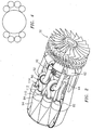
- FIG. 2 shows further details of exemplary positions of the exemplary compressor/turbine units 38 and combustors 41.
- the core airflow 514 is divided by ducts 44 into branching portions directed to the compressor sections 50 (e.g., centrifugal compressors) of each of the units 38. Rotation of the impeller of the section 50 is driven by the turbine of the turbine section 52 (e.g., a radial turbine) of the associated unit 38.
- the units 38 thus compress the flow 514 into compressed flows 516 directed to the combustor section 40.
- the compressed air is mixed with a fuel flow 518 and combusted to form combustion gas 520.
- the gas 520 is directed to the turbine of the turbine section 52 where it is partially expanded to extract the work to compress the flow 514.
- the partially expanded combustion gas flow 522 is directed to the turbine section 42.
- the turbine sections 52 of the various units 38 may be coupled to a common discharge manifold 60 feeding an upstream/inlet end of the turbine section 42.
- the exemplary flow 524 is directed via a manifold duct 62 to merge with the bypass flow 512 and form a combined flow 526. This combined flow may ultimately be discharged from the outlet 30.
- the blade stages of the turbine section 42 are co-spooled with the fan on the shaft 34.
- the positioning of the turbine section 42 forward of the combustor section 40, along with the generally forward flow through the turbine section 42 facilitates a short shaft 34 and a longitudinally compact engine.
- the configuration also hides the moving/hot surfaces of the turbine section 42 from line-of-sight exposure through the outlet. This may be advantageous for low observability properties including radar return and infrared signature.
- FIG. 1 shows further details of the exemplary combustor section 40.
- FIG. 1 shows an inner member 80 within an outer member 82.
- the airflow 516 is received through an associated conduit 84 to a volume or space 86 between the inner and outer members.
- There may be a circumferential array of the inner members 80 (one for each combustor 41).
- the outer member 82 may be a single outer member containing all or more than one of the inner members (e.g., an annular outer member).
- the exemplary inner member 80 has an aft end 90 and a fore end 92.
- the exemplary inner member 80 has a first frustoconical wall portion 94 diverging forward from the aft end 90.
- the wall portion 94 is foraminate allowing the inflow of air.
- a fuel injector 100 may be positioned at the aft end to introduce the fuel flow 518.
- An igniter 102 e.g., a sparkplug
- the divergence of the wall portion 94 helps facilitate a deflagration-to-detonation transition.
- the exemplary inner member 80 has a second wall portion 110 forward of the portion 94.
- a convergent wall portion 112 is downstream of the portion 110.
- An outlet conduit 114 connects the inner member 80 to the associated turbine section 52.
- Individual coupling of the combustors to at least the turbine section 52 prevents crosstalk between the discharge ends of the combustors. This is relevant where the combustors are operated out-of-phase so that the combustion gas discharged by one combustor is not ingested by another.
- each combustor may be coupled to receive air from the compressor section 50 of one unit 38 while discharging gases to the turbine section 52 of another unit.
- FIG. 3 shows an alternative configuration with a long shaft 34' connecting a turbine section 42' to the fan.
- the exemplary turbine section 42' is aft of the combustor section and receives combustion gases from the compressor/turbine unit array through a manifold 160' directing the combustion gases generally aftward and radially inboard of the combustors. The discharged combustion gases and bypass air mix relatively downstream.
- Exemplary firing frequency may be in the vicinity of 50-300Hz and may vary considerably depending on the scale/size of the engine and resulting impact on combustor section geometry and volume.
- Exemplary phase combinations are possible, including firing in opposed pairs to limit wobble.
- Exemplary fan spool speeds are 2000-20000 revolutions per minute (RPM), more narrowly 6000-12000 RPM.
- Exemplary speeds for the units 38 are 5000-50000 RPM, more narrowly 20000-35000 RPM as an approximation for the 6000-12000 RPM fan spool speeds under steady-state conditions.
- the combustors take a variety of forms, including shapes, positions, and orientations.
- FIG. 4 shows an exemplary configuration wherein eight combustors are grouped in two groups concentrated on respective left and right sides of the engine. This creates a wide but small height package which may be advantageous for integration into the airframe of an aircraft (e.g., a fighter aircraft, unmanned aerial vehicle, or missile).
- an aircraft e.g., a fighter aircraft, unmanned aerial vehicle, or missile.
Landscapes
- Engineering & Computer Science (AREA)
- Chemical & Material Sciences (AREA)
- Combustion & Propulsion (AREA)
- Mechanical Engineering (AREA)
- General Engineering & Computer Science (AREA)
- Structures Of Non-Positive Displacement Pumps (AREA)
- Turbine Rotor Nozzle Sealing (AREA)
Abstract
Description
- This invention relates to engines, and more particularly to hybrid pulse combustion turbine engines.
- In a conventional gas turbine engine, combustion occurs in a continuous, near constant pressure (Brayton cycle), mode. Although present gas turbine engine combustors are relatively efficient, the thermodynamic benefit to cycle efficiency associated with performing the combustion operation at a higher time-averaged pressure has led to many efforts to improve combustion.
- It has been proposed to improve thermodynamic efficiency by applying the more efficient combustion of near constant volume combustion pulse detonation engines (PDEs) to turbine engine combustors. In a generalized PDE, fuel and oxidizer (e.g., oxygen-containing gas such as air) are admitted to an elongate combustion chamber at an upstream inlet end, typically through an inlet valve as a mixture. Upon introduction of this charge, the valve is closed and an igniter is utilized to detonate the charge (either directly or through a deflagration to detonation transition). A detonation wave propagates toward the outlet at supersonic speed causing substantial combustion of the fuel/air mixture before the mixture can be substantially driven from the outlet. The result of the combustion is to rapidly elevate pressure within the chamber before substantial gas can escape inertially through the outlet. The effect of this inertial confinement is to produce near constant volume combustion.
-
U.S. Patent No. 6,442,930 , for example, suggests combustor use of PDE technology in addition to use as a thrust augmentor in engines with conventional combustors. Other pulsed combustors are shown inU.S. Patent Nos. 6,886,325 and6,901,738 . - One aspect of the invention involves a turbine engine having a case with an axis. A fan is mounted for rotation about the axis. A turbine is mechanically coupled to the fan to drive rotation of the fan about the axis. A number of compressor/turbine units are downstream of the fan and upstream of the turbine along a core flowpath. A number of combustors are coupled to the compressor/turbine units to receive air and deliver combustion gas to drive the turbine.
- In various implementations, the compressor/turbine units may be centrifugal compressor/radial turbine units, with the turbine coaxially driving the impeller by means of a connecting shaft. There may be a circumferential array of the compressor/turbine units and a circumferential array of the combustors. Each of the compressor/turbine units may be uniquely associated with a single one of the combustors and vice versa. The compressor/turbine units may be coupled to the combustor so that: the compressor of the compressor/turbine unit delivers air to the associated combustor; and the turbine of the compressor/turbine unit receives the combustion gas from the associated combustor. The turbine may be an axial turbine receiving the combustion gas from all of the compressor/turbine units. The axial turbine may be co-spooled with the fan. There may be at least eight of the compressor/turbine units and at least eight of the combustors. The combustors may be non-rotating.
- Another aspect of the invention involves a method for operating a turbine engine. Air is directed from a fan to a number of compressor/turbine units. The air is compressed in the compressor/turbine units. The air is directed to a number of combustors. The air is combusted with fuel in the combustors to produce combustion gas. Work is extracted from the combustion gas in the compressor/turbine units to drive the compression. The combustion gas is directed from the compressor/turbine units to a turbine. Work is extracted from the combustion gas in the turbine to drive rotation of the fan.
- In various implementations, the combustion gas may be directed from the turbine to join a bypass flow of air from the fan. A mass flow ratio of the flow of the air delivered to the combustors to the bypass flow may be between 1:1 and 1:3. The combusting may be a pulse combusting. The combusting may comprise detonation. The combusting may comprise operating respective ones of the combustors out of phase with each other. The method may be used in aircraft propulsion.
- The details of one or more embodiments of the invention are set forth in the accompanying drawings and the description below. Other features and advantages of the invention will be apparent from the description and drawings, and from the claims.
-
- FIG. 1 is a schematic partial longitudinal sectional view of a turbofan engine.
- FIG. 2 is a cutaway view of the engine of FIG. 1.
- FIG. 3 is a schematic partial longitudinal sectional view of an alternative engine.
- FIG. 4 is a front schematic view of a second alternative engine.
- Like reference numbers and designations in the various drawings indicate like elements.
- FIG. 1 shows a
turbofan engine 20 having centrallongitudinal axis 500, acase 22, and acore 24. Thecase 22 defines aduct 26 extending from anupstream inlet 28 to adownstream outlet 30. Of aninlet airflow 510 entering the duct, afan 32 drives abypass portion 512 and acore portion 514 along respective bypass and core flowpaths through the duct. Theexemplary fan 32 has two blade stages and two interspersed vane stages. The blade stages may be supported on ashaft 34. - As is described in further detail below, the
exemplary engine 20 also includes a circumferential array of compressor/turbine units 38, a combustor section 40 (e.g., circumferential array of combustors 41), and aturbine section 42. Other components (e.g., an augmentor and an exhaust nozzle) may also be present. FIG. 2 shows further details of exemplary positions of the exemplary compressor/turbine units 38 andcombustors 41. - The
core airflow 514 is divided byducts 44 into branching portions directed to the compressor sections 50 (e.g., centrifugal compressors) of each of theunits 38. Rotation of the impeller of thesection 50 is driven by the turbine of the turbine section 52 (e.g., a radial turbine) of the associatedunit 38. Theunits 38 thus compress theflow 514 intocompressed flows 516 directed to thecombustor section 40. In thecombustor section 40, the compressed air is mixed with afuel flow 518 and combusted to formcombustion gas 520. Thegas 520 is directed to the turbine of theturbine section 52 where it is partially expanded to extract the work to compress theflow 514. - From the
unit 38, the partially expandedcombustion gas flow 522 is directed to theturbine section 42. For example, theturbine sections 52 of thevarious units 38 may be coupled to acommon discharge manifold 60 feeding an upstream/inlet end of theturbine section 42. As theflow 522 passes through theturbine section 42 it is further expanded and discharged as aflow 524. Theexemplary flow 524 is directed via amanifold duct 62 to merge with thebypass flow 512 and form a combinedflow 526. This combined flow may ultimately be discharged from theoutlet 30. - In the exemplary engine of FIG. 1, the blade stages of the
turbine section 42 are co-spooled with the fan on theshaft 34. The positioning of theturbine section 42 forward of thecombustor section 40, along with the generally forward flow through theturbine section 42 facilitates ashort shaft 34 and a longitudinally compact engine. The configuration also hides the moving/hot surfaces of theturbine section 42 from line-of-sight exposure through the outlet. This may be advantageous for low observability properties including radar return and infrared signature. - FIG. 1 shows further details of the
exemplary combustor section 40. FIG. 1 shows aninner member 80 within anouter member 82. Theairflow 516 is received through an associatedconduit 84 to a volume orspace 86 between the inner and outer members. There may be a circumferential array of the inner members 80 (one for each combustor 41). In some variations, theouter member 82 may be a single outer member containing all or more than one of the inner members (e.g., an annular outer member). In other variations, there may be a circumferential array of theouter members 82, each containing an associated one of theinner members 80. - The exemplary
inner member 80 has anaft end 90 and afore end 92. The exemplaryinner member 80 has a firstfrustoconical wall portion 94 diverging forward from theaft end 90. Thewall portion 94 is foraminate allowing the inflow of air. In the exemplary combustor, afuel injector 100 may be positioned at the aft end to introduce thefuel flow 518. An igniter 102 (e.g., a sparkplug) may be positioned to ignite the fuel air mixture to cause combustion. The divergence of thewall portion 94 helps facilitate a deflagration-to-detonation transition. - The exemplary
inner member 80 has asecond wall portion 110 forward of theportion 94. Aconvergent wall portion 112 is downstream of theportion 110. Anoutlet conduit 114 connects theinner member 80 to the associatedturbine section 52. Individual coupling of the combustors to at least theturbine section 52 prevents crosstalk between the discharge ends of the combustors. This is relevant where the combustors are operated out-of-phase so that the combustion gas discharged by one combustor is not ingested by another. - Inlet decoupling is less critical. Thus, there may be a common
outer member 82 defining a common inlet plenum. In yet other embodiments, each combustor may be coupled to receive air from thecompressor section 50 of oneunit 38 while discharging gases to theturbine section 52 of another unit. - FIG. 3 shows an alternative configuration with a long shaft 34' connecting a turbine section 42' to the fan. The exemplary turbine section 42' is aft of the combustor section and receives combustion gases from the compressor/turbine unit array through a manifold 160' directing the combustion gases generally aftward and radially inboard of the combustors. The discharged combustion gases and bypass air mix relatively downstream.
- The effects of the pressure pulses from the individual combustors is minimized by operation out-of-phase with each other. Exemplary firing frequency may be in the vicinity of 50-300Hz and may vary considerably depending on the scale/size of the engine and resulting impact on combustor section geometry and volume. Various phase combinations are possible, including firing in opposed pairs to limit wobble. Exemplary fan spool speeds are 2000-20000 revolutions per minute (RPM), more narrowly 6000-12000 RPM. Exemplary speeds for the
units 38 are 5000-50000 RPM, more narrowly 20000-35000 RPM as an approximation for the 6000-12000 RPM fan spool speeds under steady-state conditions. - Many variations are possible. For example, the combustors take a variety of forms, including shapes, positions, and orientations. FIG. 4 shows an exemplary configuration wherein eight combustors are grouped in two groups concentrated on respective left and right sides of the engine. This creates a wide but small height package which may be advantageous for integration into the airframe of an aircraft (e.g., a fighter aircraft, unmanned aerial vehicle, or missile).
- One or more embodiments of the present invention have been described: Nevertheless, it will be understood that various modifications may be made without departing from the scope of the invention. For example, the details of any particular application will influence the configuration of the combustor. Various features of the combustor may be fully or partially integrated with features of the turbine or the compressor. If applied in a redesign of an existing turbine engine, details of the existing engine may implement details of the implementation. The rotating combustor may alternatively be used in applications beyond turbine engines. Accordingly, other embodiments are within the scope of the following claims.
Claims (21)
- A turbine engine (20) comprising:a case (22) having an axis (500);a fan (32) mounted for rotation about the axis (500);a turbine (42; 42') mechanically coupled to the fan (32) to drive rotation of the fan (32) about the axis (500);a plurality of compressor/turbine units (38) downstream of the fan (32) and upstream of the turbine (42;42') along a core flowpath; anda plurality of combustors (41), coupled to the plurality of compressor/turbine units (38)to receive air and deliver combustion gas to drive the turbine (42; 42').
- The engine of claim 1 wherein:the compressor/turbine units (38) each have a centrifugal compressor section (50) and a coaxial radial turbine section (52).
- The engine of claim 1 or 2 wherein:the compressor/turbine units (38) each have a compressor section (50) having an axial inlet and radial outlet and a coaxial turbine section (52) having a radial inlet and axial outlet.
- The engine of any preceding claim wherein
the plurality of compressor/turbine units (38) is a circumferential array of compressor/turbine units (38); and
the plurality of combustors (41) is a circumferential array of combustors (41). - The engine of any preceding claim wherein:each of the plurality of compressor/turbine units (38) is uniquely associated with a single one of the combustors (41) and vice versa and coupled so that:the compressor (50) of the compressor/turbine unit (38) delivers the air to the associated combustor (41); andthe turbine (52) of the compressor/turbine unit (38) receives the combustion gas from the associated combustor (41).
- The engine of any preceding claim wherein:said turbine (42; 42') is an axial turbine and receiving the combustion gas from all of the compressor/turbine units (38).
- The engine of claim 6 wherein:the axial turbine (42; 42') is co-spooled with the fan (32).
- The engine of any preceding claim wherein:there are at least eight of the compressor/turbine units (38) and at least eight of the combustors (41).
- The engine of any preceding claim wherein:the combustors (41) are non-rotating.
- The engine of any preceding claim wherein each combustor (41) comprises:an outer wall (82);an inner wall (80), within the outer wall (82);a space (86) between the inner and outer walls (80, 82) coupled to receive air from at least an associated one of the compressor/turbine units (38);a fuel injector (100) positioned to introduce fuel to the air; anda space within the inner wall (80) coupled to deliver combustion gas to at least an associated one of the compressor/turbine units (38).
- The engine of any preceding claim wherein:flow of the combustion gas to the plurality of compressor/turbine units (38) is axially toward the fan (32).
- A method for operating a turbine engine (20) comprising:directing air from a fan (32) to a plurality of compressor/turbine units (38);compressing the air in the compressor/turbine units (38);directing the air to a plurality of combustors (41);combusting the air with fuel in the combustors (41) to produce combustion gas;extracting work from the combustion gas in the compressor/turbine units (38) to drive said compressing;directing the combustion gas from the compressor/turbine units (38) to a turbine (42; 42'); andextracting work from the combustion gas in the turbine (42; 42') to drive rotation of the fan (32).
- The method of claim 12 wherein:the compressing is centrifugal; andthe extracting work from the combustion gas in each of the compressor/turbine units (38) comprises passing the combustion gas radially inward toward an axis of the unit (38).
- The method of claim 12 or 13 further comprising:directing the combustion gas from the turbine (42; 42') to join a bypass flow of air (512) from the fan (32).
- The method of claim 14 wherein:a mass flow ratio of the flow of the air delivered to the combustors (41) to the bypass flow is between 1:1 and 1:3.
- The method of any of claims 12 to 15 wherein:the combusting is a pulsed combusting.
- The method of claim 16 wherein:the combusting comprises detonation.
- The method of claim 16 or 17 wherein:the pulsed combusting in each of the combustors has a frequency of 50-300 Hz.
- The method of claim 16, 17 or 18 wherein:the combusting comprises operating respective ones of the combustors (41) out of phase with each other.
- The method of any of claims 12 to 19 used in aircraft propulsion.
- The method of any of claims 12 to 20 wherein:the compressor/turbine units (38) are running at a speed of at least 20000 RPM; andthe fan (32) rotates at a speed of 6000-12000 RPM.
Applications Claiming Priority (1)
| Application Number | Priority Date | Filing Date | Title |
|---|---|---|---|
| US11/445,977 US7752835B2 (en) | 2006-06-01 | 2006-06-01 | Pulsed combustion engine |
Publications (1)
| Publication Number | Publication Date |
|---|---|
| EP1862660A1 true EP1862660A1 (en) | 2007-12-05 |
Family
ID=38283282
Family Applications (1)
| Application Number | Title | Priority Date | Filing Date |
|---|---|---|---|
| EP07251290A Withdrawn EP1862660A1 (en) | 2006-06-01 | 2007-03-27 | Pulsed combustion gas turbine engine |
Country Status (3)
| Country | Link |
|---|---|
| US (1) | US7752835B2 (en) |
| EP (1) | EP1862660A1 (en) |
| JP (1) | JP2007321756A (en) |
Families Citing this family (7)
| Publication number | Priority date | Publication date | Assignee | Title |
|---|---|---|---|---|
| US8104289B2 (en) | 2007-10-09 | 2012-01-31 | United Technologies Corp. | Systems and methods involving multiple torque paths for gas turbine engines |
| US8616005B1 (en) | 2009-09-09 | 2013-12-31 | Dennis James Cousino, Sr. | Method and apparatus for boosting gas turbine engine performance |
| US20120272656A1 (en) * | 2011-04-29 | 2012-11-01 | United Technologies Corporation | Multiple core variable cycle gas turbine engine and method of operation |
| US9470153B2 (en) * | 2011-10-05 | 2016-10-18 | United Technologies Corporation | Combined pump system for engine TMS AOC reduction and ECS loss elimination |
| US9222409B2 (en) | 2012-03-15 | 2015-12-29 | United Technologies Corporation | Aerospace engine with augmenting turbojet |
| US9140212B2 (en) * | 2012-06-25 | 2015-09-22 | United Technologies Corporation | Gas turbine engine with reverse-flow core having a bypass flow splitter |
| US20250027444A1 (en) * | 2023-07-19 | 2025-01-23 | Borgwarner Inc. | Rotating detonation combustor system and method of operating the rotating detonation combustor system |
Citations (4)
| Publication number | Priority date | Publication date | Assignee | Title |
|---|---|---|---|---|
| GB1020145A (en) * | 1964-12-07 | 1966-02-16 | Rolls Royce | Power plant e.g. for jet propulsion of aircraft |
| US3368352A (en) * | 1965-01-30 | 1968-02-13 | Rolls Royce | Gas turbine engines |
| EP1533473A1 (en) * | 2003-11-20 | 2005-05-25 | General Electric Company | Triple circuit turbine cooling |
| US6901738B2 (en) * | 2003-06-26 | 2005-06-07 | United Technologies Corporation | Pulsed combustion turbine engine |
Family Cites Families (16)
| Publication number | Priority date | Publication date | Assignee | Title |
|---|---|---|---|---|
| US2476179A (en) * | 1942-08-12 | 1949-07-12 | Bristol Aeroplane Co Ltd | Heat exchanger |
| US2575682A (en) * | 1944-02-14 | 1951-11-20 | Lockheed Aircraft Corp | Reaction propulsion aircraft power plant having independently rotating compressor and turbine blading stages |
| US2694291A (en) * | 1948-02-07 | 1954-11-16 | Henning C Rosengart | Rotor and combustion chamber arrangement for gas turbines |
| US2748564A (en) * | 1951-03-16 | 1956-06-05 | Snecma | Intermittent combustion gas turbine engine |
| US3045894A (en) * | 1957-05-22 | 1962-07-24 | Frederick W Ross | Gas turbine engine |
| US3010281A (en) * | 1957-12-24 | 1961-11-28 | Adolph J Cervenka | Toroidal combustion chamber |
| US3269119A (en) * | 1960-03-16 | 1966-08-30 | Nathan C Price | Turbo-jet powerplant with toroidal combustion chamber |
| US3269120A (en) * | 1964-07-16 | 1966-08-30 | Curtiss Wright Corp | Gas turbine engine with compressor and turbine passages in a single rotor element |
| US5832715A (en) * | 1990-02-28 | 1998-11-10 | Dev; Sudarshan Paul | Small gas turbine engine having enhanced fuel economy |
| US6442930B1 (en) | 2000-03-31 | 2002-09-03 | General Electric Company | Combined cycle pulse detonation turbine engine |
| EP1362984B1 (en) * | 2002-05-16 | 2007-04-25 | ROLLS-ROYCE plc | Gas turbine engine |
| US6886325B2 (en) | 2002-12-30 | 2005-05-03 | United Technologies Corporation | Pulsed combustion engine |
| FR2858999B1 (en) * | 2003-08-18 | 2005-11-11 | Snecma Moteurs | TURBOMACHINE FOR AIRCRAFT WITH REDUCED NOISE EMISSIONS |
| US7328570B2 (en) * | 2004-09-01 | 2008-02-12 | General Electric Company | Pulse detonation system for a gas turbine engine having multiple spools |
| US20060086078A1 (en) * | 2004-10-21 | 2006-04-27 | Paul Marius A | Universal Carnot propulsion systems for turbo rocketry |
| US7628018B2 (en) * | 2008-03-12 | 2009-12-08 | Mowill R Jan | Single stage dual-entry centriafugal compressor, radial turbine gas generator |
-
2006
- 2006-06-01 US US11/445,977 patent/US7752835B2/en active Active
-
2007
- 2007-03-27 EP EP07251290A patent/EP1862660A1/en not_active Withdrawn
- 2007-03-29 JP JP2007086555A patent/JP2007321756A/en active Pending
Patent Citations (4)
| Publication number | Priority date | Publication date | Assignee | Title |
|---|---|---|---|---|
| GB1020145A (en) * | 1964-12-07 | 1966-02-16 | Rolls Royce | Power plant e.g. for jet propulsion of aircraft |
| US3368352A (en) * | 1965-01-30 | 1968-02-13 | Rolls Royce | Gas turbine engines |
| US6901738B2 (en) * | 2003-06-26 | 2005-06-07 | United Technologies Corporation | Pulsed combustion turbine engine |
| EP1533473A1 (en) * | 2003-11-20 | 2005-05-25 | General Electric Company | Triple circuit turbine cooling |
Also Published As
| Publication number | Publication date |
|---|---|
| US20070277500A1 (en) | 2007-12-06 |
| US7752835B2 (en) | 2010-07-13 |
| JP2007321756A (en) | 2007-12-13 |
Similar Documents
| Publication | Publication Date | Title |
|---|---|---|
| US6666018B2 (en) | Combined cycle pulse detonation turbine engine | |
| JP4705727B2 (en) | Combined cycle pulse detonation turbine engine | |
| CN109028142B (en) | Propulsion system and method of operating the same | |
| CN109028146B (en) | Hybrid combustor assembly and method of operation | |
| CN109028149B (en) | Variable geometry rotary detonation combustor and method of operating same | |
| CN109028144B (en) | Integral vortex rotary detonation propulsion system | |
| EP1431563B1 (en) | Apparatus for generating gas turbine engine thrust | |
| US20190093553A1 (en) | Reverse-flow core gas turbine engine with a pulse detonation system | |
| US20180231256A1 (en) | Rotating Detonation Combustor | |
| US8365514B1 (en) | Hybrid turbofan engine | |
| US6901738B2 (en) | Pulsed combustion turbine engine | |
| CN112797442A (en) | Method and system for rotary detonation combustion | |
| US20180355792A1 (en) | Annular throats rotating detonation combustor | |
| CN115199438B (en) | Turbine rotary rocket combined engine | |
| EP1828683B1 (en) | Combustor for turbine engine | |
| EP2472090A2 (en) | A gas engine turbine comprising a thrust augmentation system | |
| JP2007321756A (en) | Turbine engine and its operating method | |
| EP1435447B1 (en) | Pulsed combustion turbine engine | |
| US2924071A (en) | de paravicini | |
| RU43039U1 (en) | COMBINED AIR-ROCKET ENGINE |
Legal Events
| Date | Code | Title | Description |
|---|---|---|---|
| PUAI | Public reference made under article 153(3) epc to a published international application that has entered the european phase |
Free format text: ORIGINAL CODE: 0009012 |
|
| AK | Designated contracting states |
Kind code of ref document: A1 Designated state(s): AT BE BG CH CY CZ DE DK EE ES FI FR GB GR HU IE IS IT LI LT LU LV MC MT NL PL PT RO SE SI SK TR |
|
| AX | Request for extension of the european patent |
Extension state: AL BA HR MK YU |
|
| 17P | Request for examination filed |
Effective date: 20080604 |
|
| 17Q | First examination report despatched |
Effective date: 20080709 |
|
| AKX | Designation fees paid |
Designated state(s): DE GB |
|
| STAA | Information on the status of an ep patent application or granted ep patent |
Free format text: STATUS: THE APPLICATION IS DEEMED TO BE WITHDRAWN |
|
| 18D | Application deemed to be withdrawn |
Effective date: 20081121 |